JP2017036484A - Metallic product production method - Google Patents
Metallic product production method Download PDFInfo
- Publication number
- JP2017036484A JP2017036484A JP2015159085A JP2015159085A JP2017036484A JP 2017036484 A JP2017036484 A JP 2017036484A JP 2015159085 A JP2015159085 A JP 2015159085A JP 2015159085 A JP2015159085 A JP 2015159085A JP 2017036484 A JP2017036484 A JP 2017036484A
- Authority
- JP
- Japan
- Prior art keywords
- powder
- surface coating
- coating material
- metal
- impeller
- Prior art date
- Legal status (The legal status is an assumption and is not a legal conclusion. Google has not performed a legal analysis and makes no representation as to the accuracy of the status listed.)
- Pending
Links
Images


Classifications
-
- B—PERFORMING OPERATIONS; TRANSPORTING
- B22—CASTING; POWDER METALLURGY
- B22F—WORKING METALLIC POWDER; MANUFACTURE OF ARTICLES FROM METALLIC POWDER; MAKING METALLIC POWDER; APPARATUS OR DEVICES SPECIALLY ADAPTED FOR METALLIC POWDER
- B22F10/00—Additive manufacturing of workpieces or articles from metallic powder
- B22F10/20—Direct sintering or melting
- B22F10/28—Powder bed fusion, e.g. selective laser melting [SLM] or electron beam melting [EBM]
-
- B—PERFORMING OPERATIONS; TRANSPORTING
- B33—ADDITIVE MANUFACTURING TECHNOLOGY
- B33Y—ADDITIVE MANUFACTURING, i.e. MANUFACTURING OF THREE-DIMENSIONAL [3-D] OBJECTS BY ADDITIVE DEPOSITION, ADDITIVE AGGLOMERATION OR ADDITIVE LAYERING, e.g. BY 3-D PRINTING, STEREOLITHOGRAPHY OR SELECTIVE LASER SINTERING
- B33Y10/00—Processes of additive manufacturing
-
- B—PERFORMING OPERATIONS; TRANSPORTING
- B22—CASTING; POWDER METALLURGY
- B22F—WORKING METALLIC POWDER; MANUFACTURE OF ARTICLES FROM METALLIC POWDER; MAKING METALLIC POWDER; APPARATUS OR DEVICES SPECIALLY ADAPTED FOR METALLIC POWDER
- B22F10/00—Additive manufacturing of workpieces or articles from metallic powder
- B22F10/30—Process control
- B22F10/36—Process control of energy beam parameters
-
- B—PERFORMING OPERATIONS; TRANSPORTING
- B22—CASTING; POWDER METALLURGY
- B22F—WORKING METALLIC POWDER; MANUFACTURE OF ARTICLES FROM METALLIC POWDER; MAKING METALLIC POWDER; APPARATUS OR DEVICES SPECIALLY ADAPTED FOR METALLIC POWDER
- B22F12/00—Apparatus or devices specially adapted for additive manufacturing; Auxiliary means for additive manufacturing; Combinations of additive manufacturing apparatus or devices with other processing apparatus or devices
- B22F12/50—Means for feeding of material, e.g. heads
- B22F12/55—Two or more means for feeding material
-
- Y—GENERAL TAGGING OF NEW TECHNOLOGICAL DEVELOPMENTS; GENERAL TAGGING OF CROSS-SECTIONAL TECHNOLOGIES SPANNING OVER SEVERAL SECTIONS OF THE IPC; TECHNICAL SUBJECTS COVERED BY FORMER USPC CROSS-REFERENCE ART COLLECTIONS [XRACs] AND DIGESTS
- Y02—TECHNOLOGIES OR APPLICATIONS FOR MITIGATION OR ADAPTATION AGAINST CLIMATE CHANGE
- Y02P—CLIMATE CHANGE MITIGATION TECHNOLOGIES IN THE PRODUCTION OR PROCESSING OF GOODS
- Y02P10/00—Technologies related to metal processing
- Y02P10/25—Process efficiency
Landscapes
- Engineering & Computer Science (AREA)
- Chemical & Material Sciences (AREA)
- Manufacturing & Machinery (AREA)
- Materials Engineering (AREA)
- Physics & Mathematics (AREA)
- Plasma & Fusion (AREA)
- Powder Metallurgy (AREA)
- Other Surface Treatments For Metallic Materials (AREA)
- Structures Of Non-Positive Displacement Pumps (AREA)
Abstract
Description
本発明は、金属基材と表面コーティング材(以下、「表面コーティング」ともいう。)からなる金属製品を製造する方法に関する。 The present invention relates to a method for producing a metal product comprising a metal substrate and a surface coating material (hereinafter also referred to as “surface coating”).
従来から、金属製品を製造する場合に、金属基材による成形体の表面に表面コーティングを被覆させることがある。以下、金属製品として、羽根車(インペラ)を用いて液体の流体(以下、単に「流体」という。)を吸引して吐出する渦巻きポンプを例にとって説明する。 Conventionally, when a metal product is manufactured, a surface coating is sometimes applied to the surface of a molded body made of a metal substrate. Hereinafter, an example of a spiral pump that sucks and discharges a liquid fluid (hereinafter simply referred to as “fluid”) using an impeller as a metal product will be described.
渦巻きポンプは、用途に応じて、耐腐食性、耐摩耗性等を要求されることが多い。例えば、流体が塩分や化学物質を含む場合(海水、工業水等)、渦巻きポンプには耐腐食性が要求される。耐腐食性が低いと、例えば、羽根車表面に、化学的な腐食(コロージョン)が生じることがある。 Centrifugal pumps are often required to have corrosion resistance, wear resistance, etc., depending on the application. For example, when the fluid contains salt or a chemical substance (seawater, industrial water, etc.), the spiral pump is required to have corrosion resistance. When the corrosion resistance is low, for example, chemical corrosion (corrosion) may occur on the surface of the impeller.
また、流体が土砂などの固形物を含む場合(河川水等)、渦巻きポンプには耐摩耗性が要求される。耐摩耗性が低いと、例えば、羽根車表面に、土砂などの固形物による摩耗(スラリーエロージョン)が生じることがある。 In addition, when the fluid contains solids such as earth and sand (river water or the like), the spiral pump is required to have wear resistance. When the wear resistance is low, for example, wear (slurry erosion) due to solid matter such as earth and sand may occur on the surface of the impeller.
さらに、流体の種類によらず、例えば、羽根車表面において、キャビテーションエロージョンが生じることがある。キャビテーションエロージョンとは、流体において局所的に飽和蒸気圧よりも低圧力になった部分でキャビテーション(気泡)が発生し、そのキャビテーションが破裂して消滅するときの衝撃力による損傷のことである。 Furthermore, cavitation erosion may occur on the impeller surface, for example, regardless of the type of fluid. Cavitation erosion is damage caused by impact force when cavitation (bubbles) is generated in a part of the fluid where the pressure is locally lower than the saturated vapor pressure, and the cavitation bursts and disappears.
例えば、渦巻きポンプの羽根車には、耐腐食性に優れ低価格で入手可能なオーステナイト系ステンレス鋼が用いられることが多い。さらに、耐腐食性を向上する材料として、二相ステンレス鋼や、ニッケル基合金等も用いられている。しかし、羽根車の材質のみで耐腐食性と耐摩耗性の両者を向上させることは困難であるため、その両者を向上させるために、例えば、ステンレス鋼の羽根車の表面に硬質の表面コーティングを被覆する場合がある。 For example, an austenitic stainless steel that is excellent in corrosion resistance and available at a low price is often used for the impeller of a spiral pump. Furthermore, duplex stainless steel, nickel-base alloys, and the like are also used as materials for improving corrosion resistance. However, since it is difficult to improve both corrosion resistance and wear resistance with only the impeller material, in order to improve both, for example, a hard surface coating is applied to the surface of a stainless steel impeller. May be covered.
また、渦巻きポンプには、羽根車の表面の他にも耐摩耗性等を向上するために表面コーティングを被覆する部位がある。例えば、渦巻きポンプには、回転する羽根車や回転軸と固定側のケーシングとの間に流体の漏れを防止するシール部がある。このシール部は、できるだけ流体漏れを低減するために、回転側部材と固定側部材の間隔が小さく設計されている。そのため、シール部では回転側部材と固定側部材が摺動する可能性がある。摺動する回転側部材、固定側部材の両方が同じ表面材質であると、噛り付いてしまう可能性がある。また、このような摺動する部分に関しては、内部の流体の腐食性や土砂などの状況によって、摺動による摩耗がさらに進んでしまう可能性があり、耐腐食性、耐摩耗性等を向上させるためにも、回転側部材と固定側部材の一方の表面に表面コーティングを被覆する場合が多い。 In addition to the surface of the impeller, the spiral pump has a portion that covers a surface coating in order to improve wear resistance and the like. For example, the spiral pump has a seal portion that prevents fluid leakage between a rotating impeller and a rotating shaft and a fixed casing. In order to reduce fluid leakage as much as possible, this seal portion is designed so that the interval between the rotating side member and the stationary side member is small. Therefore, there is a possibility that the rotating side member and the stationary side member slide at the seal portion. If both the rotating side member and the stationary side member that slide are made of the same surface material, there is a possibility that they will bite. In addition, with respect to such sliding parts, there is a possibility that wear due to sliding may be further advanced depending on the corrosiveness of the internal fluid and the situation such as earth and sand, improving the corrosion resistance, wear resistance, etc. For this reason, a surface coating is often coated on one surface of the rotating side member and the stationary side member.
これに関連し、例えば特許文献1には、「課題を解決するための手段」に、「この発明は、耐摩耗性、耐キャビテーション性などが要求される部品の被覆部材として、ステンレス鋼からなるポンプ部品の母材の表面に、Cr、Moを含有し、Si、Bのうち少なくとも1種を含有し、残りがNiと不可避不純物からなるNi−Cr−Mo系合金、または、残りがCoと不可避不純物からなるCo−Cr−Mo系合金を被覆した第1の被膜と、Cr、Mo、Ni、Fe、Si、Cを含有し、残りがCoと不可避不純物とからなるCo基合金からなる硬質材料を被覆した第2の被膜を備えたことを特徴とするものである。」(参照)と記載されている。つまり、この技術では、羽根車表面や軸スリーブに対してそのような被膜を形成することによって、耐摩耗性、耐キャビテーションエロージョン性を向上させている。
In relation to this, for example,
また、例えば特許文献2には、請求項1に、「ポンプケーシングとインペラを備え、該ポンプケーシングと該インペラ入口との間にシール部を具備する遠心式ポンプにおいて、前記シール部における前記インペラ側の部材と前記ポンプケーシング側の部材とのいずれかの対向面に相手面材質より軟質のCr、Moを含むNi合金を溶射法或いは溶接法により所定厚さに肉盛し、相対面との硬度差をHB(ブリネル硬さ)=50以上とし、前記インペラ側の部材と前記ポンプケーシング側の部材は、同材の二相系ステンレス鋼で形成されており、前記Ni合金を肉盛した部材は、PREN値が40以上の二相系ステンレス鋼からなり、前記Ni合金は、Cr+Mo≧30%のNi合金である」と記載されている。つまり、この技術では、羽根車シール部に相当するインペラリング又はケーシングリングに、高耐腐食性Ni合金を溶射又は溶接にて肉盛することで、耐腐食性を向上させている。
Further, for example, in
また、特にクローズド羽根車(側板付きの羽根車)に対して、例えば特許文献3には、「要約」に、「硬質コーティングは、それら各々の中点に最小低圧コーティング厚さおよび最小高圧コーティング厚さを有する。最小低圧コーティング厚さならびに最小高圧コーティング厚さは、それぞれ、出口遠位端における最大出口コーティング厚さの、または入口遠位端における最大入口コーティング厚さのいずれか1つの約0.085〜約0.8倍の範囲である。」と記載されている。つまり、この技術では、クローズド羽根車の羽根の位置によって、クラッド(被覆)施工のし易さを考慮して、耐腐食性等のためのコーティングの厚さを調整している。
In particular, for closed impellers (impellers with side plates), for example,
一方で、3D(Dimensions)プリンタやラピットプロトタイピングによる三次元積層造形技術を用いて樹脂材で製造されるインペラに対する被覆技術に関して、例えば特許文献4には、請求項1に、「迅速模型製造方法により、予め設計された形状の非金属製の基材を形成する工程と、前記基材の表面に表面金属層を被覆する工程とを有することを特徴とする羽根車の製造方法」と記載されている。つまり、この技術では、迅速模型製造方法(三次元積層造形技術)で製造された非金属樹脂の羽根車の表面に金属層を被覆する。
On the other hand, regarding a covering technique for an impeller manufactured from a resin material using a 3D (Dimensions) printer or a three-dimensional additive manufacturing technique by rapid prototyping, for example,
三次元積層造形技術を用いれば、複雑な構造の製品も容易に製造することができる。ここで、例えば、渦巻きポンプにおける羽根車は、流体を昇圧するときの負荷や、回転により加わる遠心力のため、樹脂材では強度的に不十分である場合が多い。したがって、羽根車に対しては、金属材料を適用できる三次元積層造形技術を用いることが望まれる。 If the three-dimensional additive manufacturing technology is used, a product having a complicated structure can be easily manufactured. Here, for example, an impeller in a centrifugal pump is often insufficient in terms of strength due to a load when boosting a fluid or a centrifugal force applied by rotation. Therefore, it is desired to use a three-dimensional additive manufacturing technique that can apply a metal material to the impeller.
金属材料を適用できる三次元積層造形技術には、粉末供給法や粉末焼結積層法がある。例えば、特許文献4に記載されている粉末供給法は、粉末材料をレーザで溶融しながら造形する手法である。この粉末供給法では、凝固前の溶融材料が自重で変形する可能性があるため、造形可能な形状に制限がある。一方、特許文献5に記載されているように、粉末焼結積層法では、一層ごとに素材粉末を敷き詰めて、レーザで所定部分を溶解、焼結する。この粉末焼結積層法では、レーザで焼結した部分がその下部にある粉末で支えられるため、造形可能な形状に制限が少なく、複雑な形状を造形することが可能である。
The three-dimensional additive manufacturing technology to which a metal material can be applied includes a powder supply method and a powder sintering method. For example, the powder supply method described in
しかしながら、粉末焼結積層法を用いて金属製品を造形した場合でも、表面コーティングが必要な場合は被覆作業を別途行わなければならず、作業が煩雑であるという問題がある。さらに、金属製品の形状が複雑な場合は、表面コーティングの被覆作業が煩雑であるというだけでなく、溶射やクラッド溶接では施工上の制約で表面コーティングの被覆作業が困難、または不可能な場合がある。 However, even when a metal product is shaped using the powder sintering lamination method, if surface coating is required, a coating operation must be performed separately, and there is a problem that the operation is complicated. Furthermore, when the shape of the metal product is complicated, not only is the surface coating coating operation complicated, but it may be difficult or impossible to coat the surface coating due to construction restrictions in thermal spraying or cladding welding. is there.
例えば、クローズド羽根車では、羽根の外側に側板が存在するため、羽根面の周りの空間が狭く、溶射機や溶接機による作業は容易ではない。また、狭い空間に挿入できるような溶射機や溶接機を用いる場合もあるが、溶射や溶接の向きによって表面コーティング材を十分に溶着できない場合もある。また、アーク溶射、フレーム溶射、HVOF(High Velocity Oxygen Fuel)溶射を施工の困難さと品質に応じて羽根の部分ごとに選択して行う方法もある。しかしながら、施工方法を部位によって変えると、施工コストが増大するとともに、施工部位の境界での信頼性が低下することも考えられる。 For example, in a closed impeller, since a side plate exists on the outside of the blade, the space around the blade surface is narrow, and it is not easy to work with a thermal sprayer or a welder. In some cases, a thermal sprayer or a welder that can be inserted into a narrow space may be used, but the surface coating material may not be sufficiently welded depending on the direction of thermal spraying or welding. There is also a method of performing arc spraying, flame spraying, and HVOF (High Velocity Oxygen Fuel) spraying for each blade portion according to the difficulty and quality of construction. However, when the construction method is changed depending on the part, the construction cost increases, and the reliability at the boundary of the construction part may be reduced.
そこで、本発明は、金属基材と表面コーティング材からなる金属製品を、形状の複雑さに関係なく容易に製造することを課題とする。 Then, this invention makes it a subject to manufacture easily the metal product which consists of a metal base material and a surface coating material irrespective of the complexity of a shape.
前記課題を解決するために、本発明は、金属基材と表面コーティング材からなる金属製品を、金属基材粉末と表面コーティング材粉末を用いて粉末焼結積層法によって製造する金属製品製造方法であって、前記金属製品に関する3次元CAD(Computer Aided Design)データに基づいて、積層方向の層ごとの断面図データを作成するステップを実行した後、前記層ごとに、前記断面図データに基づいて、造形ステージ上に、前記金属基材の位置には前記金属基材粉末を配置し、それ以外の位置には前記表面コーティング材粉末を配置するステップと、レーザによって、前記配置した金属基材粉末と、前記断面図データにおける前記表面コーティング材の位置にある前記表面コーティング材粉末と、を溶解、焼結することで固化するステップと、を繰り返し実行することを特徴とする。
その他の手段については後記する。
In order to solve the above problems, the present invention provides a metal product manufacturing method for manufacturing a metal product comprising a metal base material and a surface coating material by a powder sintering lamination method using the metal base material powder and the surface coating material powder. Then, after executing the step of creating cross-sectional data for each layer in the stacking direction based on three-dimensional CAD (Computer Aided Design) data relating to the metal product, for each layer, based on the cross-sectional data The metal substrate powder is disposed on the modeling stage at the position of the metal substrate, and the surface coating material powder is disposed at other positions, and the disposed metal substrate powder by a laser. And solidifying the surface coating material powder at the position of the surface coating material in the cross-sectional view data by melting and sintering. Characterized in that it returns execution.
Other means will be described later.
本発明によれば、金属基材と表面コーティング材からなる金属製品を、形状の複雑さに関係なく容易に製造することができる。 ADVANTAGE OF THE INVENTION According to this invention, the metal product which consists of a metal base material and a surface coating material can be manufactured easily irrespective of the complexity of a shape.
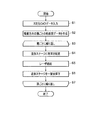
以下、本発明の実施形態について、図面を参照して説明する。まず、図1、図2を参照して、本実施形態における粉末焼結積層法による金属製品製造方法の概要について説明する。ここでは、金属基材と表面コーティング材からなる金属製品を、金属基材粉末と表面コーティング材粉末を用いて、三次元積層造形技術の一種である粉末焼結積層法によって製造する。図1は、粉末焼結積層法を説明するための模式図であり、主な構成として、造形ステージ101、粉末を配置するためのノズル102、103、粉末を溶解、焼結するためのレーザ装置104、製造を制御する制御装置105が備えられている。また、図2は、本実施形態における粉末焼結積層法による金属製品製造方法の処理の流れを示すフローチャートである。
Hereinafter, embodiments of the present invention will be described with reference to the drawings. First, with reference to FIG. 1, FIG. 2, the outline | summary of the metal product manufacturing method by the powder sintering lamination method in this embodiment is demonstrated. Here, a metal product composed of a metal substrate and a surface coating material is produced by a powder sintering lamination method, which is a kind of three-dimensional additive manufacturing technology, using the metal substrate powder and the surface coating material powder. FIG. 1 is a schematic diagram for explaining a powder sintering lamination method. As a main configuration, a
まず、制御装置105は、予め作成された、金属製品に関する3次元CAD(Computer Aided Design)データを入力する(ステップS1)。金属製品が例えば羽根車である場合、3次元CADデータは、羽根車本体となる金属基材とその表面を覆う表面コーティング材とのそれぞれの3次元位置情報を含む。
次に、制御装置105は、3次元CADデータに基づいて、積層方向の層ごとの断面図データを作成する(ステップS2)。
First, the
Next, the
次に、制御装置105は、層ごとにステップS4〜S6の処理を繰り返す(ステップS3〜S7)。
制御装置105は、断面図データに基づいて、造形ステージ101(以下、符号無しで「造形ステージ」という場合もある。)上に、1層分、金属基材の位置にはノズル102を用いて金属基材粉末を配置し、それ以外の位置にはノズル103を用いて表面コーティング材粉末を配置する(ステップS4)。
Next, the
Based on the cross-sectional view data, the
次に、制御装置105は、断面図データに基づいて、レーザ装置104によるレーザ照射によって、金属基材の位置の金属基材粉末と、表面コーティング材の位置にある表面コーティング材粉末と、を溶解、焼結することで固化する(ステップS5)。なお、このとき、表面コーティング材の位置以外の位置にある表面コーティング材粉末は、粉末のまま残り、最後に回収される。
次に、制御装置105は、造形ステージ101を一層分降下させる(ステップS6)。
Next, the
Next, the
このようにして、層ごとにステップS4〜S6の処理を繰り返すことで、金属基材と表面コーティング材からなる金属製品を、金属基材粉末と表面コーティング材粉末を用いて粉末焼結積層法によって、形状の複雑さに関係なく容易に製造することができる。以下、金属製品として、クローズド羽根車、ケーシングリング、軸スリーブを例にとって、具体的に説明する。 In this way, by repeating the processing of steps S4 to S6 for each layer, a metal product composed of a metal base material and a surface coating material is obtained by a powder sintering lamination method using the metal base material powder and the surface coating material powder. It can be easily manufactured regardless of the complexity of the shape. Hereinafter, a closed impeller, a casing ring, and a shaft sleeve will be specifically described as metal products.
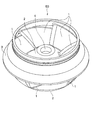
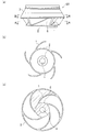
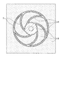
図3は、クローズド羽根車の構造例を示す斜視図である。図4において、(a)は図3のクローズド羽根車の側面図であり、(b)は(a)のA−A矢視断面図であり、(c)は(a)のB−B矢視断面図である。 FIG. 3 is a perspective view showing a structural example of a closed impeller. 4, (a) is a side view of the closed impeller of FIG. 3, (b) is a cross-sectional view taken along line AA of (a), and (c) is a BB arrow of (a). FIG.
図3、図4に示すように、クローズド羽根車50は、5枚の羽根1と、中心軸が挿入される軸穴4と一体となった心板2と、外周側を覆う側板3と、を備える。なお、このように側板のある羽根車をクローズド羽根車と呼び、一方、側板のない羽根車をオープン羽根車と呼ぶ。
As shown in FIGS. 3 and 4, the
クローズド羽根車50では、流体的な性能(高効率、広運転範囲)を向上させるために、羽根1が複雑な曲面となっている。したがって、従来の溶射機や溶接機による表面コーティング被覆作業は容易ではない。また、図4(a)のA−A矢視断面図(図4(b))では側板3がなく、図4(a)のB−B矢視断面図(図4(c))では側板3がある。また、羽根1自体もA−A矢視断面図(図4(b))とB−B矢視断面図(図4(c))では曲面の形状が異なる。つまり、クローズド羽根車50は、鉛直方向に一様な構造ではないので、粉末供給法で製造すると造形途中の金属が自重で変形してしまう可能性があるので、本実施形態では粉末焼結積層法で製造する。
In the
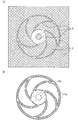
図5(a)は、クローズド羽根車50を粉末焼結積層法で製造するために金属基材粉末と表面コーティング材粉末を造形ステージ上に配置した状態を示す図である。造形ステージ上で、金属基材粉末6をクローズド羽根車50の羽根1、心板2および側板3の位置(図4(c)参照)に配置し、表面コーティング材粉末7をそれ以外の位置に配置する(図2のステップS4)。そして、レーザ装置104(図1)によるレーザ照射によって、羽根1、心板2および側板3の位置の金属基材粉末6と、表面コーティング材の位置にある表面コーティング材粉末7と、を溶解、焼結することで固化する(図2のステップS5)。これにより、図5(b)に示すように、金属基材6aの表面に表面コーティング材7aを被覆した状態とすることができる。
FIG. 5A is a diagram showing a state in which the metal base powder and the surface coating material powder are arranged on the modeling stage in order to manufacture the
このようにして、金属基材と表面コーティング材を一体成形してクローズド羽根車50を製造できる。そして、金属基材と表面コーティング材を一体成形できるため、それらの間での接合強度が、溶接や溶着の場合に比べて高くなるという利点がある。また、溶接や溶射によって被覆する表面コーティングは、厚さが数百μmから数mm程度が一般的であるが、粉末焼結積層法の場合は表面コーティングの厚さを自由に変更することが可能で、さらに、要求される耐腐食性や耐摩耗性に応じてコーティング厚さに分布をつけることができるという利点もある。
In this way, the
なお、金属基材粉末6としては、低合金鋼やステンレス鋼、アルミニウム合金などの粉末が挙げられる。また、表面コーティング材粉末7としては、ニッケル基合金やコバルト基合金、高耐腐食性ステンレス鋼(二相ステンレス鋼)などの合金や、タングステンカーバイドにコバルトやニッケル、クロムなどのバインダを混合したものなどが挙げられる。ただし、ここで示した材料は例を示すものであり、これらの材料に限定されない。
Examples of the
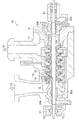
次に、図6、図7を参照して、ケーシングリングを製造する場合について説明する。図6に示すように、横軸多段ポンプ10は、5段の羽根車14を備えている。横軸多段ポンプ10では、吸込口12から流体を吸込み、吐出口17から加圧した流体を吐出する。5段の羽根車14は回転軸13に取り付けられ、回転軸13は両端の軸受21で支えられている。
Next, a case where a casing ring is manufactured will be described with reference to FIGS. As shown in FIG. 6, the horizontal axis
ケーシング11と回転軸13のすき間からの流体漏れを最小限にするために、軸封装置20a、20b(シール部)がそれぞれ回転軸13とケーシング11に取り付けられている。軸封装置20a、20bは摺動部位となるため、いずれか一方を硬質の表面コーティングで被覆する場合が多い。
In order to minimize fluid leakage from the gap between the
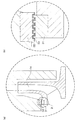
ここで、図7(a)は、図6の領域Cの拡大図である。また、図7(b)は、図7(a)の領域Dの拡大図である。羽根車14の入口部分には、羽根車14の吸込み側と吐出し側をシールするためにインペラリング31とケーシングリング32が取り付けられている。このインペラリング31とケーシングリング32は、シール性能を向上するために、図7(b)に示すようにどちらか一方もしくは両方の表面に複雑な凹凸が設けられる場合がある。図7(b)では、インペラリング31とケーシングリング32の両方の表面に複雑な凹凸を設けた構造を示している。
Here, Fig.7 (a) is an enlarged view of the area | region C of FIG. Moreover, FIG.7 (b) is an enlarged view of the area | region D of Fig.7 (a). An
これらのインペラリング31とケーシングリング32は、作動流体中の土砂を巻き込みながら摺動するため、インペラリング31の摺動面もしくはケーシングリング32の摺動面の一方に、硬質の表面コーティングを被覆する必要がある。ここでは、ケーシングリング32の摺動面に表面コーティング33が被覆されている。
Since the
なお、図5のような図示は省略するが、ケーシングリング32についても、前記したクローズド羽根車50の場合と同様に、粉末焼結積層法で金属基材粉末と表面コーティング材粉末によって製造することができる。具体的には、ケーシングリング32は、円筒部材であるため、粉末焼結積層法では軸方向に積層することになる。そして、造形ステージ上で、金属基材粉末をケーシングリング基材部分に配置し、表面コーティング材粉末をそれ以外の位置に配置し、レーザ光で金属基材粉末とその近傍の表面コーティング材粉末を溶解、焼結することで、凹凸をもつケーシングリング32を表面コーティング33とともに容易に製造することができる。
In addition, although illustration like FIG. 5 is abbreviate | omitted, also about the
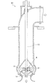
次に、図8、図9を参照して、軸スリーブを製造する場合について説明する。図8に示すように、立軸ポンプ60は、図の下方から流体を吸込み、羽根車14で昇圧し、図の上方から右向きに吐出する構造となっている。羽根車14の上部には回転軸13を支える軸受21が配置されている。この軸受21を含む領域Eを拡大したものが図9である。
Next, with reference to FIG. 8 and FIG. 9, the case where a shaft sleeve is manufactured will be described. As shown in FIG. 8, the
図9に示すように、回転軸13には、摺動部位に軸スリーブ44が焼き嵌め等で固定されている。軸スリーブ44の表面には、硬質の表面コーティング46が被覆されている。一方、軸受21は、軸受ハウジング41と、軸受ハウジング41に固定された軸スリーブ45と、軸スリーブ45の表面に取り付けられた軸受パット材43と、を備えている。軸受パット材43と表面コーティング46が摺動するため、軸受パット材43には摺動性の良いPTFE(Poly Tetra Fluoro Ethylene)やPEEK(Poly Ether Ether Ketone)等の樹脂やセラミックス材が用いられる。軸スリーブ44は、表面の表面コーティング46によって、作動流体中の土砂を巻き込みながら軸受パット材43と摺動しても摩耗しない。
As shown in FIG. 9, a
なお、図5のような図示は省略するが、軸スリーブ44についても、前記したクローズド羽根車50の場合と同様に、粉末焼結積層法で金属基材粉末と表面コーティング材粉末によって製造することができる。具体的には、軸スリーブ44は、円筒部材であるため、粉末焼結積層法では軸方向に積層することになる。そして、造形ステージ上で、金属基材粉末を軸スリーブ基材部分に配置し、表面コーティング材粉末をそれ以外の位置に配置し、レーザ光で金属基材粉末とその近傍の表面コーティング材粉末を溶解、焼結することで、軸スリーブ44を表面コーティング46とともに容易に製造することができる。
In addition, although illustration like FIG. 5 is abbreviate | omitted, also about the
次に、図5で説明したクローズド羽根車50の製造方法を一部変更した実施形態について説明する。図5で説明した製造方法では、溶解、焼結しない表面コーティング材粉末7が大量に残材として回収されるが、一般にこの残材には不純物が含まれてしまうため、不純物の分離処理をしないと再利用が難しい。そして、表面コーティング材粉末7は一般に高価であるため、表面コーティング材粉末7の残材が多く、不純物の分離処理をせず再利用しない場合、製造コストが高くなってしまうという側面がある。また、不純物の分離処理をするとしても、それにコストがかかってしまうという問題もある。
Next, an embodiment in which the manufacturing method of the
そこで、その点を改善するために、金属基材粉末、表面コーティング材粉末のほかに、表面コーティング材粉末よりも融点が高い高融点粉末を用いる方法について説明する。 In order to improve this point, a method of using a high melting point powder having a melting point higher than that of the surface coating material powder in addition to the metal base material powder and the surface coating material powder will be described.
造形ステージ上に、図10に示すように、金属基材粉末6をクローズド羽根車50の羽根1、心板2および側板3の位置(図4(c)参照)に配置し、それらの近傍には表面コーティング材粉末7を配置し、それら以外の位置には高融点粉末8を配置する。そして、金属基材粉末6と表面コーティング材粉末7をレーザで溶解、焼結する際、高融点粉末8が溶解、焼結しないように、レーザ光の強さを調節する。焼結後の状態は、図5(b)と同様である。
On the modeling stage, as shown in FIG. 10, the
2種類以上の粉末を用いて粉末焼結積層法で形状を製作する場合、隣あう2種類の粉末がともに溶解、焼結すると、それらの粉末の成分が混ざりあってしまう。表面コーティング材粉末7には耐腐食性、耐摩耗性の高い材料を用いているが、それに高融点粉末8の成分が混合してしまうとそれらの機能が低下してしまう。
When manufacturing a shape by a powder sintering lamination method using two or more kinds of powders, if two adjacent kinds of powders are dissolved and sintered together, the components of those powders are mixed. The surface
図5に示す金属基材粉末6と表面コーティング材粉末7の2種類を用いた場合は、これら2者の境界で成分が混合してしまうが、コーティング厚さをある程度とることによって表面コーティング材7aの表層をその成分のみにできる。つまり、耐腐食性、耐摩耗性は表面コーティング材7aの表層で維持されていれば良いので、図5の構成では金属基材粉末6と表面コーティング材粉末7の成分の混合は問題とならない。
When two types of
一方で、図10に示すような3種類の粉末を用いる場合、表面コーティング材粉末7と高融点粉末8にも、粉末間の境界ができてしまう。そこで、高融点粉末8を溶解しないようにして、表面コーティング材粉末7と高融点粉末8の成分が混合しないようにすることが必要となる。ただし、表面コーティング材粉末7が溶解、焼結したときに、高融点粉末8が溶解はしないが付着してしまうこともあるため、この粉末焼結積層法でのクローズド羽根車50の製造後に表面を研削して高融点粉末8の成分を除去してもよい。
On the other hand, when three types of powders as shown in FIG. 10 are used, the surface
なお、高融点粉末8としては、表面コーティング材粉末7よりも融点が高い必要があり、また、安価なものが望ましく、例えばアルミナ等が挙げられるが、これに限定されない。
The high melting point powder 8 needs to have a melting point higher than that of the surface
また、クローズド羽根車50だけでなく、ケーシングリング32や軸スリーブ44についても、金属基材粉末と表面コーティング材粉末のほかに高融点粉末を用いて製造してもよい。
Further, not only the closed
このように、本実施形態によれば、金属基材と表面コーティング材からなる金属製品(クローズド羽根車50、ケーシングリング32、軸スリーブ44)を、金属基材粉末と表面コーティング材粉末を用いて粉末焼結積層法によって製造することで、形状の複雑さに関係なく容易に製造することができる。
Thus, according to the present embodiment, a metal product (closed
また、金属基材粉末と表面コーティング材粉末のほかに高融点粉末を用いることで、製造コストを低減することができる。 In addition to the metal base powder and the surface coating material powder, the production cost can be reduced by using the high melting point powder.
以上で実施形態の説明を終えるが、本発明の態様はこれらに限定されるものではない。例えば、前記した実施形態は本発明をわかりやすく説明するために詳細に説明したものであり、必ずしも説明した全ての構成を備えるものに限定されるものではない。 This is the end of the description of the embodiments, but the aspects of the present invention are not limited to these. For example, the above-described embodiment has been described in detail for easy understanding of the present invention, and is not necessarily limited to the one having all the configurations described.
また、ある実施形態の構成の一部を他の実施形態の構成に置き換えることも可能であり、また、ある実施形態の構成に他の実施形態の構成を加えることも可能である。
その他、具体的な構成について、本発明の主旨を逸脱しない範囲で適宜変更が可能である。
Further, a part of the configuration of an embodiment can be replaced with the configuration of another embodiment, and the configuration of another embodiment can be added to the configuration of an embodiment.
In addition, about a concrete structure, it can change suitably in the range which does not deviate from the main point of this invention.
1 羽根
2 心板
3 側板
4 軸穴
6 金属基材粉末
6a 金属基材
7 表面コーティング材粉末
7a 表面コーティング材
8 高融点粉末
10 横軸多段ポンプ
11 ケーシング
12 吸込口
13 回転軸
14 羽根車
17 吐出口
20a、20b 軸封装置
21 軸受
31 インペラリング
32 ケーシングリング
33 表面コーティング
41 軸受ハウジング
43 軸受パット材
44 軸スリーブ
45 軸スリーブ
46 表面コーティング
50 クローズド羽根車
60 立軸ポンプ
101 造形ステージ
102 ノズル
103 ノズル
104 レーザ装置
105 制御装置
1
Claims (3)
前記金属製品に関して、本体となる金属基材とその表面を覆う表面コーティング材とのそれぞれの3次元位置情報を含む3次元CAD(Computer Aided Design)データに基づいて、積層方向の層ごとの断面図データを作成するステップを実行した後、
前記層ごとに、前記断面図データに基づいて、
造形ステージ上に、前記金属基材の位置には前記金属基材粉末を配置し、それ以外の位置には前記表面コーティング材粉末を配置するステップと、
レーザによって、前記配置した金属基材粉末と、前記表面コーティング材の位置にある前記表面コーティング材粉末と、を溶解、焼結することで固化するステップと、を繰り返し実行する
ことを特徴とする金属製品製造方法。 A metal product manufacturing method for manufacturing a metal product composed of a metal substrate and a surface coating material by a powder sintering lamination method using a metal substrate powder and a surface coating material powder,
Regarding the metal product, a cross-sectional view for each layer in the stacking direction based on 3D CAD (Computer Aided Design) data including 3D position information of a metal base material as a main body and a surface coating material covering the surface of the metal base material After running the data creation step,
For each layer, based on the cross-sectional data,
On the modeling stage, the metal substrate powder is disposed at the position of the metal substrate, and the surface coating material powder is disposed at other positions.
The metal is characterized by repeatedly performing the step of solidifying by melting and sintering the placed metal base powder and the surface coating material powder at the position of the surface coating material by a laser. Product manufacturing method.
前記金属製品に関して、本体となる金属基材とその表面を覆う表面コーティング材とのそれぞれの3次元位置情報を含む3次元CAD(Computer Aided Design)データに基づいて、積層方向の層ごとの断面図データを作成するステップを実行した後、
前記層ごとに、前記断面図データに基づいて、
造形ステージ上に、前記金属基材の位置には前記金属基材粉末を配置し、前記表面コーティング材の位置には前記表面コーティング材粉末を配置し、それら以外の位置には前記高融点粉末を配置するステップと、
前記レーザによって、前記配置した前記金属基材粉末と前記表面コーティング材粉末を溶解、焼結することで固化するステップと、を繰り返し実行する
ことを特徴とする金属製品製造方法。 Metal manufactured by a powder sintering lamination method using a metal substrate powder, a surface coating material powder, and a high melting point powder having a melting point higher than that of the surface coating material powder. A product manufacturing method comprising:
Regarding the metal product, a cross-sectional view for each layer in the stacking direction based on 3D CAD (Computer Aided Design) data including 3D position information of a metal base material as a main body and a surface coating material covering the surface of the metal base material After running the data creation step,
For each layer, based on the cross-sectional data,
On the modeling stage, the metal substrate powder is disposed at the position of the metal substrate, the surface coating material powder is disposed at the position of the surface coating material, and the high melting point powder is disposed at other positions. Placing step;
The method for producing a metal product, characterized in that the step of solidifying the arranged metal base powder and the surface coating material powder by melting and sintering with the laser is repeated.
Priority Applications (2)
| Application Number | Priority Date | Filing Date | Title |
|---|---|---|---|
| JP2015159085A JP2017036484A (en) | 2015-08-11 | 2015-08-11 | Metallic product production method |
| CN201610575557.7A CN106424722A (en) | 2015-08-11 | 2016-07-20 | Metal product manufacturing method |
Applications Claiming Priority (1)
| Application Number | Priority Date | Filing Date | Title |
|---|---|---|---|
| JP2015159085A JP2017036484A (en) | 2015-08-11 | 2015-08-11 | Metallic product production method |
Publications (2)
| Publication Number | Publication Date |
|---|---|
| JP2017036484A true JP2017036484A (en) | 2017-02-16 |
| JP2017036484A5 JP2017036484A5 (en) | 2018-09-13 |
Family
ID=58049186
Family Applications (1)
| Application Number | Title | Priority Date | Filing Date |
|---|---|---|---|
| JP2015159085A Pending JP2017036484A (en) | 2015-08-11 | 2015-08-11 | Metallic product production method |
Country Status (2)
| Country | Link |
|---|---|
| JP (1) | JP2017036484A (en) |
| CN (1) | CN106424722A (en) |
Cited By (7)
| Publication number | Priority date | Publication date | Assignee | Title |
|---|---|---|---|---|
| CN105817626A (en) * | 2016-05-19 | 2016-08-03 | 西安交通大学 | Molten coating forming device and method of metal material gradient components |
| WO2017170729A1 (en) * | 2016-03-29 | 2017-10-05 | 三菱重工コンプレッサ株式会社 | Impeller production method by fused deposition modeling using dissimilar materials, and impeller |
| JP6279824B1 (en) * | 2017-02-24 | 2018-02-14 | 三菱重工コンプレッサ株式会社 | Impeller manufacturing method |
| JP6288661B1 (en) * | 2017-02-24 | 2018-03-07 | 三菱重工コンプレッサ株式会社 | Impeller manufacturing method and impeller flow path extending jig |
| JP2018176400A (en) * | 2017-04-21 | 2018-11-15 | 株式会社不二製作所 | Impeller for acceleration of abrasive material in blast processing device, blast processing device, and method for manufacturing impeller |
| JP2021031773A (en) * | 2019-08-29 | 2021-03-01 | ▲華▼中科技大学Huazhong University Of Science And Technology | System and method for compositely molding lamination molding and surface coating |
| JP2021148026A (en) * | 2020-03-17 | 2021-09-27 | 株式会社神戸製鋼所 | Impeller and method for manufacturing impeller |
Families Citing this family (4)
| Publication number | Priority date | Publication date | Assignee | Title |
|---|---|---|---|---|
| JP7116495B2 (en) * | 2017-03-14 | 2022-08-10 | ヴァンベーエヌ コンポネンツ アクチエボラグ | High carbon cobalt alloy |
| JP2018204087A (en) * | 2017-06-08 | 2018-12-27 | 株式会社日立製作所 | Additive manufacturing device |
| CN109989061A (en) * | 2019-04-28 | 2019-07-09 | 江西省科学院应用物理研究所 | A kind of method that laser 3D printing prepares wearable hard alloy ball grinder liner plate |
| CN117067380B (en) * | 2023-10-11 | 2024-01-26 | 成都永益泵业股份有限公司 | Aluminum oxide pump overcurrent component and manufacturing method thereof |
Citations (2)
| Publication number | Priority date | Publication date | Assignee | Title |
|---|---|---|---|---|
| US20050268998A1 (en) * | 2002-09-17 | 2005-12-08 | Georg Bostanjoglo | Method for producing a three-dimensional moulded body |
| WO2014107204A2 (en) * | 2012-10-08 | 2014-07-10 | Siemens Aktiengesellschaft | Additive manufacture of turbine component with multiple materials |
Family Cites Families (7)
| Publication number | Priority date | Publication date | Assignee | Title |
|---|---|---|---|---|
| JP2002012901A (en) * | 2000-06-29 | 2002-01-15 | Hitachi Ltd | Three-dimensional article, method for producing the same, and three-dimensional article-shaping system |
| CN100446897C (en) * | 2006-08-02 | 2008-12-31 | 南昌航空工业学院 | Method for precinct laser sintering fast manufacture metal die |
| DE102007006478B4 (en) * | 2007-02-09 | 2011-06-30 | Universität Stuttgart, 70174 | Apparatus and method for supplying sinterable powder to an application site of a laser sintering device |
| CN103521769B (en) * | 2013-09-24 | 2015-10-28 | 西安交通大学 | A kind of increasing material manufacture method be shaped based on many material particles high velocity jet |
| CN104338931B (en) * | 2014-10-09 | 2015-06-17 | 湖南华曙高科技有限责任公司 | Method and device for preparing functionally graded structural component |
| CN104399981B (en) * | 2014-12-14 | 2016-07-06 | 机械科学研究总院先进制造技术研究中心 | A kind of three-dimensional printing-forming method of metal-base composites |
| CN104439243A (en) * | 2015-01-06 | 2015-03-25 | 彭晓领 | Laser 3D printing manufacturing method of metal gradient material |
-
2015
- 2015-08-11 JP JP2015159085A patent/JP2017036484A/en active Pending
-
2016
- 2016-07-20 CN CN201610575557.7A patent/CN106424722A/en active Pending
Patent Citations (2)
| Publication number | Priority date | Publication date | Assignee | Title |
|---|---|---|---|---|
| US20050268998A1 (en) * | 2002-09-17 | 2005-12-08 | Georg Bostanjoglo | Method for producing a three-dimensional moulded body |
| WO2014107204A2 (en) * | 2012-10-08 | 2014-07-10 | Siemens Aktiengesellschaft | Additive manufacture of turbine component with multiple materials |
Cited By (14)
| Publication number | Priority date | Publication date | Assignee | Title |
|---|---|---|---|---|
| WO2017170729A1 (en) * | 2016-03-29 | 2017-10-05 | 三菱重工コンプレッサ株式会社 | Impeller production method by fused deposition modeling using dissimilar materials, and impeller |
| CN105817626A (en) * | 2016-05-19 | 2016-08-03 | 西安交通大学 | Molten coating forming device and method of metal material gradient components |
| US11333162B2 (en) | 2017-02-24 | 2022-05-17 | Mitsubishi Heavy Industries Compressor Corporation | Impeller manufacturing method and impeller flow path elongation jig |
| JP6279824B1 (en) * | 2017-02-24 | 2018-02-14 | 三菱重工コンプレッサ株式会社 | Impeller manufacturing method |
| JP6288661B1 (en) * | 2017-02-24 | 2018-03-07 | 三菱重工コンプレッサ株式会社 | Impeller manufacturing method and impeller flow path extending jig |
| WO2018154730A1 (en) * | 2017-02-24 | 2018-08-30 | 三菱重工コンプレッサ株式会社 | Impeller manufacturing method and impeller flow path elongation jig |
| WO2018154737A1 (en) * | 2017-02-24 | 2018-08-30 | 三菱重工コンプレッサ株式会社 | Production method for impeller |
| US10821520B2 (en) | 2017-02-24 | 2020-11-03 | Mitsubishi Heavy Industries Compressor Corporation | Production method for impeller |
| JP2018176400A (en) * | 2017-04-21 | 2018-11-15 | 株式会社不二製作所 | Impeller for acceleration of abrasive material in blast processing device, blast processing device, and method for manufacturing impeller |
| JP7016507B2 (en) | 2017-04-21 | 2022-02-07 | 株式会社不二製作所 | An impeller for accelerating abrasives in a blasting device, a blasting device, and a method for manufacturing the impeller. |
| JP2021031773A (en) * | 2019-08-29 | 2021-03-01 | ▲華▼中科技大学Huazhong University Of Science And Technology | System and method for compositely molding lamination molding and surface coating |
| JP7089662B2 (en) | 2019-08-29 | 2022-06-23 | ▲華▼中科技大学 | Composite molding system and method of laminated molding and surface coating |
| JP2021148026A (en) * | 2020-03-17 | 2021-09-27 | 株式会社神戸製鋼所 | Impeller and method for manufacturing impeller |
| JP7364504B2 (en) | 2020-03-17 | 2023-10-18 | 株式会社神戸製鋼所 | Impeller and impeller manufacturing method |
Also Published As
| Publication number | Publication date |
|---|---|
| CN106424722A (en) | 2017-02-22 |
Similar Documents
| Publication | Publication Date | Title |
|---|---|---|
| JP2017036484A (en) | Metallic product production method | |
| EP3148731B1 (en) | Method for manufacturing a turbomachine component | |
| EP3215290B1 (en) | System and method for additive manufacturing of turbomachine components | |
| JP6118350B2 (en) | Manufacture of impellers for turbomachinery | |
| US12090569B2 (en) | Method of manufacturing a component of a rotary machine and component manufactured using said method | |
| US10322575B2 (en) | Hot gas path component and methods of manufacture | |
| JP2016199804A (en) | Process for producing article | |
| EP3103570A1 (en) | Additive manufacturing methods and hybrid articles using brazeable structures made by additive manufacturing | |
| US11009017B2 (en) | Reciprocating compressor valve body made by additive manufacturing | |
| CN109202087A (en) | The impeller for manufacturing the method for the impeller of rotary machine and being manufactured with such method | |
| JP2015511539A (en) | Electrode and method for manufacturing the electrode | |
| EP3655636B1 (en) | Acoustic attenuator for a turbomachine and methodology for additively manufacturing said acoustic attenuator | |
| CN110177920B (en) | Turbine bucket with radial support, shim and associated turbine rotor | |
| JP2022544565A (en) | Additively manufactured extruder components | |
| CA2992466A1 (en) | Composite suction liners and applications thereof | |
| CN110799755B (en) | Techniques using additive manufacturing to improve pump performance with trimmed impellers | |
| EP3822004A1 (en) | Fused filament fabrication of abradable coatings | |
| Beiker Kair et al. | Additive manufacturing and production of metallic parts in automotive industry: A case study on technical, economic and environmental sustainability aspects | |
| US11090721B2 (en) | Method for modifying the dimensions of a cast iron pump part | |
| CA3212801A1 (en) | Manufacture of an impeller in a hybrid process | |
| US9574573B2 (en) | Wear resistant slurry pump parts produced using hot isostatic pressing | |
| Geyer | Powder based additive manufacturing methods LMF/LMD–requirements, comparison and applications | |
| JP2024525841A (en) | Lightweight hydraulic design for improved 3D printability | |
| Baier et al. | Electroplating of AM wax models for the production of internal structures | |
| KR20240087836A (en) | Multi-metallic mechanical retaining hoops and technology for their manufacture |
Legal Events
| Date | Code | Title | Description |
|---|---|---|---|
| A621 | Written request for application examination |
Free format text: JAPANESE INTERMEDIATE CODE: A621 Effective date: 20180329 |
|
| A521 | Request for written amendment filed |
Free format text: JAPANESE INTERMEDIATE CODE: A523 Effective date: 20180730 |
|
| A131 | Notification of reasons for refusal |
Free format text: JAPANESE INTERMEDIATE CODE: A131 Effective date: 20190129 |
|
| A977 | Report on retrieval |
Free format text: JAPANESE INTERMEDIATE CODE: A971007 Effective date: 20190130 |
|
| A02 | Decision of refusal |
Free format text: JAPANESE INTERMEDIATE CODE: A02 Effective date: 20190723 |