EP3074314B1 - Pickup and delivery station for products - Google Patents
Pickup and delivery station for products Download PDFInfo
- Publication number
- EP3074314B1 EP3074314B1 EP14781272.1A EP14781272A EP3074314B1 EP 3074314 B1 EP3074314 B1 EP 3074314B1 EP 14781272 A EP14781272 A EP 14781272A EP 3074314 B1 EP3074314 B1 EP 3074314B1
- Authority
- EP
- European Patent Office
- Prior art keywords
- products
- grip means
- track
- carriages
- movement
- Prior art date
- Legal status (The legal status is an assumption and is not a legal conclusion. Google has not performed a legal analysis and makes no representation as to the accuracy of the status listed.)
- Active
Links
Images





Classifications
-
- B—PERFORMING OPERATIONS; TRANSPORTING
- B65—CONVEYING; PACKING; STORING; HANDLING THIN OR FILAMENTARY MATERIAL
- B65B—MACHINES, APPARATUS OR DEVICES FOR, OR METHODS OF, PACKAGING ARTICLES OR MATERIALS; UNPACKING
- B65B35/00—Supplying, feeding, arranging or orientating articles to be packaged
- B65B35/30—Arranging and feeding articles in groups
- B65B35/36—Arranging and feeding articles in groups by grippers
- B65B35/38—Arranging and feeding articles in groups by grippers by suction-operated grippers
-
- B—PERFORMING OPERATIONS; TRANSPORTING
- B25—HAND TOOLS; PORTABLE POWER-DRIVEN TOOLS; MANIPULATORS
- B25J—MANIPULATORS; CHAMBERS PROVIDED WITH MANIPULATION DEVICES
- B25J15/00—Gripping heads and other end effectors
- B25J15/0052—Gripping heads and other end effectors multiple gripper units or multiple end effectors
-
- B—PERFORMING OPERATIONS; TRANSPORTING
- B25—HAND TOOLS; PORTABLE POWER-DRIVEN TOOLS; MANIPULATORS
- B25J—MANIPULATORS; CHAMBERS PROVIDED WITH MANIPULATION DEVICES
- B25J15/00—Gripping heads and other end effectors
- B25J15/06—Gripping heads and other end effectors with vacuum or magnetic holding means
- B25J15/0616—Gripping heads and other end effectors with vacuum or magnetic holding means with vacuum
-
- B—PERFORMING OPERATIONS; TRANSPORTING
- B65—CONVEYING; PACKING; STORING; HANDLING THIN OR FILAMENTARY MATERIAL
- B65B—MACHINES, APPARATUS OR DEVICES FOR, OR METHODS OF, PACKAGING ARTICLES OR MATERIALS; UNPACKING
- B65B29/00—Packaging of materials presenting special problems
- B65B29/02—Packaging of substances, e.g. tea, which are intended to be infused in the package
- B65B29/022—Packaging of substances, e.g. tea, which are intended to be infused in the package packaging infusion material into capsules
-
- B—PERFORMING OPERATIONS; TRANSPORTING
- B65—CONVEYING; PACKING; STORING; HANDLING THIN OR FILAMENTARY MATERIAL
- B65B—MACHINES, APPARATUS OR DEVICES FOR, OR METHODS OF, PACKAGING ARTICLES OR MATERIALS; UNPACKING
- B65B5/00—Packaging individual articles in containers or receptacles, e.g. bags, sacks, boxes, cartons, cans, jars
- B65B5/08—Packaging groups of articles, the articles being individually gripped or guided for transfer to the containers or receptacles
-
- B—PERFORMING OPERATIONS; TRANSPORTING
- B65—CONVEYING; PACKING; STORING; HANDLING THIN OR FILAMENTARY MATERIAL
- B65B—MACHINES, APPARATUS OR DEVICES FOR, OR METHODS OF, PACKAGING ARTICLES OR MATERIALS; UNPACKING
- B65B5/00—Packaging individual articles in containers or receptacles, e.g. bags, sacks, boxes, cartons, cans, jars
- B65B5/10—Filling containers or receptacles progressively or in stages by introducing successive articles, or layers of articles
- B65B5/105—Filling containers or receptacles progressively or in stages by introducing successive articles, or layers of articles by grippers
-
- B—PERFORMING OPERATIONS; TRANSPORTING
- B65—CONVEYING; PACKING; STORING; HANDLING THIN OR FILAMENTARY MATERIAL
- B65G—TRANSPORT OR STORAGE DEVICES, e.g. CONVEYORS FOR LOADING OR TIPPING, SHOP CONVEYOR SYSTEMS OR PNEUMATIC TUBE CONVEYORS
- B65G47/00—Article or material-handling devices associated with conveyors; Methods employing such devices
- B65G47/74—Feeding, transfer, or discharging devices of particular kinds or types
- B65G47/90—Devices for picking-up and depositing articles or materials
- B65G47/91—Devices for picking-up and depositing articles or materials incorporating pneumatic, e.g. suction, grippers
- B65G47/918—Devices for picking-up and depositing articles or materials incorporating pneumatic, e.g. suction, grippers with at least two picking-up heads
Definitions
- the present invention relates to a pickup and delivery station for products, particularly adapted for products with a mutually complementary shape and/or products that are identical and are arranged alternately "upright” and "upturned”.
- Packaging apparatuses are known which are used to create a set of products that are mutually arranged according to a preset configuration and to insert them into a box or other package.
- This type of apparatus is adapted to pick up products from a specific storage area of a workstation upstream (which is adapted to sort them according to preset criteria) by way of corresponding grip means.
- Each apparatus further comprises movement elements that are adapted to transfer the products that have been picked up with the grip means into the specific package.
- Errors during insertion can result in damage being done to the package (which usually is made of cardboard) or it being impossible to close it (because the products are arranged untidily inside it).
- US 2013/299310 A1 discloses a product conveyance installation having a tool for handling and grouping together products which are aligned one behind another and which are separated by a given spacing.
- the tool comprises a row of supports which are each able to carry a grasping element for grasping a product, the supports being mounted such as to be able to move on at least one rail, each support being connected to an adjacent support by attachment means each comprising a rod that connects two adjacent supports and also a member for locking the position of at least one of the two adjacent supports on the rod.
- the locking member may be deactivated in order to adjust the distance between two supports to the distance between two products.
- the principal aim of the present invention is to solve the above mentioned drawbacks, by providing a pickup and delivery station for products which is simple and adapted to ensure high performance levels in terms of boxing speed.
- an object of the invention is to provide a pickup and delivery station for products which is simple to manage and maintain.
- Another object of the invention is to provide a pickup and delivery station for products which is versatile and adapted to pack the products in boxes of various different formats.
- Another object of the present invention is to provide a pickup and delivery station for products which is low cost, easily and practically implemented and safely applied.
- the reference numeral 1 generally designates a pickup and delivery station for products A.
- the products A can preferably be constituted by capsules for espresso coffee machines; however, the possibility is not ruled out of using the station 1 for picking up and delivering other products with a mutually complementary shape and/or products that are arranged alternately upright and upturned.
- the products are then inserted by the station 1 into a box B, of suitable shape and size for containing a specific set of products A and/or of multiple groups of products A (delivered during successive and consecutive operations of the station 1).
- the station 1 comprises a movement arm 2 that is articulated with respect to a fixed frame 3.
- the arm 2 supports, at its free end, at least one respective grip means 4 for at least one product A.
- the free end of the arm 2 in turn comprises at least one track 5 for at least two carriages 6 for supporting at least one respective shaft 7 that supports the grip means 4.
- Each at least one shaft 7 of a respective grip means 4 is coupled to a second linear actuator 9 that is perpendicular to the first actuator 8 for the offset of the respective grip means 4 with respect to the contiguous ones.
- the tracks 5 are a plurality, are mutually side by side and are parallel, so as to define respective guide lanes for defined series of carriages 6 which can slide independently on each one of them.
- each track 5 comprises plurality of carriages 6 which can slide: the carriage 6a, i.e. the farthest one from the end of the articulated arm 2, is fixed on the track 5 (integral with it) so as to constitute a stroke limiter for the other carriages 6 that are present on that track 5.
- a pushing action exerted by the first actuator 8 determines the compaction (mutual approach) of the carriages 6 (and thus also of the grip means 4 that are integral therewith) into abutment against the fixed carriage 6a, which is arranged substantially at the end of the track 5.
- the first linear actuator 8 in such case comprises a rack-and-pinion assembly 10: the pinion is keyed to the shaft of a movement motor that is controlled by an adapted control and management unit; the rack 10, on the other hand, is integral with the carriage 6 that is closest to the end of the arm 2 (i.e., the carriage 6 that is closest to the rack 10).
- the rotation of the motor determines the advancement/retraction of the rack 10, with consequent movement of the carriage 6 associated therewith.
- the other carriages 6 which can slide on the same track 5 will follow the movements of the one that was actuated by the rack 10 according to the presence of adapted deviation and transmission elements, or according to the presence of elastic elements interposed between contiguous carriages 6.
- the stroke limiter reference point will always be constituted by the fixed carriage 6a.
- the second linear actuator 9 is instead constituted by a cylinder, of type preferably selected from between pneumatic and hydraulic.
- the shaft 7 is thus integral with the movable stem of the pneumatic cylinder 9, thus transmitting the movements imparted by the cylinder 9 to the grip means 4 arranged at its end, in order to vary the height thereof.
- a respective second linear actuator 9 for the longitudinal translation of the shaft 7, with consequent height variation of the respective grip means 4 is interposed between each respective carriage 6 and each shaft 7 of each grip means 4 that is present thereon.
- the grip means 4 comprises at least one sucker which is connected, by way of respective ducts, to centralized controlled suction means; at least one section of such ducts comprises at least one valve that is controlled by a control and management unit for the adjustment of the connection and disconnection times of the sucker to and from the suction means.
- the movement arm 2 articulated to a fixed frame 3 comprises, according to an embodiment that is particularly efficient and is simple to implement, a first beam 11 that is pivoted to the frame 3, a second beam 12 that is pivoted to the end 11a of the first beam 11, and a supporting bracket 13 for the at least one track 5 which is coupled rotatably to the end 12a of the second beam 12.
- Movement elements are interposed between the frame 3 and the first beam 11, between the second beam 12 and the first beam 11 and between the bracket 13 and the second beam 12, and are controlled by the control and management unit that controls the entire device, in order to actuate the mutual rotations of such components.
- the tracks 5 are mutually side by side on the bracket 13 according to groupings that comprise a predefined number of equidistant tracks 5.
- the bracket 13 comprises preferably at least two side-by-side groupings, which are mutually separated by empty spaces: this makes it possible to define a number of sets of grip means 6 that will operate simultaneously to pick up and compact (or nest) the products A.
- a first set of grip means 4 could pick up respective products A, compact (nest) them and insert them into a specific box B.
- a second set could then execute the same operation, thus depositing a second layer of products A into the box B.
- the number of superimposed layers will be such as to ensure that the box B is completely filled.
- Operation of the station 1 is the following.
- the arm 2 brings the grip means 4 proximate to and in alignment with respective products A that are present on a gathering surface on which they are neatly arranged.
- the controlled valves activate the suction means and the suckers of the grip means 4 couple stably to the surface facing thereto of the product A (first step of gripping, shown in the accompanying Figure 7 ).
- the arm 2 will lift the products A (second step of lifting, shown in the accompanying Figure 8 ).
- the second actuators 9 which are constituted by pneumatic cylinders in the preferred embodiment
- the first actuators 8 then bring the carriages 6 mutually closer together, with consequent compaction of the products A held by the grip means 4 (fourth step of compaction, or nesting, shown in the accompanying Figure 10 ).
- the compaction is preferably bidirectional: the second actuators 9, in an embodiment that is particularly efficient and functional, in fact also comprise a rail 8a along which the tracks 5 can slide transversely in order to bring the grip means 4 closer transversely as well during the compaction.
- the grip means 4 undergo a mutual approach in the longitudinal direction thanks to the movement of the carriages 6 on the tracks 5 and a mutual approach in the transverse direction thanks to the movement of the tracks 5 on the rail 8a.
- the rail 8a comprises respective controlled movement motors for managing the compaction of the tracks 5 which can slide thereupon.
- the controlled movement motors can include a motor element that is associated with a drive cam that is coupled to the various different tracks 5: the possibility is not excluded of adopting any other type of conventional movement motor.
- the second actuators 9 thus eliminate the staggering of the grip means 4 (fifth step of realigning the compacted products, shown in the accompanying Figure 11 ).
- the arm 2 at this point transfers the aligned and compacted products A to above of the box B (sixth step of moving the products A, shown in the accompanying Figure 12 ).
- the protection of the present invention also covers a machine 14 for boxing products A which comprises a line 15 for the supply and sorting of products A on a gathering surface 16 and at least one conveyance line 17 of boxes B, arranged to the side of the gathering surface 16.
- a station 1 Arranged externally to the conveyance line 17 of boxes B is a station 1 for picking up products A from the surface 16 and subsequently inserting them into a box B that is present on the conveyance line 17.
- the station 1 comprises a movement arm 2 that is articulated with respect to a fixed frame 3.
- the arm 2 supports, at its free end, at least one respective grip means 4 for at least one product A.
- the free end of the arm 2 comprises at least one track 5 for at least two carriages 6 for supporting at least one respective shaft 7 that supports a grip means 4.
- At least one shaft 7 of a grip means 4 is preferably coupled to a second linear actuator 9 that is perpendicular to the first actuator 8 for the offset of the respective grip means 4 with respect to the contiguous ones.
- the present invention solves the problems explained previously, by providing a pickup and delivery station 1 for products A which is simple and adapted to ensure high performance levels in terms of packaging speed (also with regard to the possibility of making successive, overlapped layers of products A in a single box B).
- the station 1 is simple to manage and maintain: in fact it is constituted by unrelated components that facilitate substitution operations and which, in the event of malfunction, do not result in the overall outage of the station (but only a possible reduction in performance).
- the station 1 is versatile and adapted to pack the products A in boxes of various different formats: in fact it is possible to reconfigure the groupings of tracks 5 in order to adapt them to the specific dimensions of the box B present on the line 17.
- the materials employed, as well as the dimensions, may be any according to requirements and to the state of the art.
Landscapes
- Engineering & Computer Science (AREA)
- Mechanical Engineering (AREA)
- Robotics (AREA)
- Container Filling Or Packaging Operations (AREA)
- Specific Conveyance Elements (AREA)
- Refuse Collection And Transfer (AREA)
- Vending Machines For Individual Products (AREA)
Description
- The present invention relates to a pickup and delivery station for products, particularly adapted for products with a mutually complementary shape and/or products that are identical and are arranged alternately "upright" and "upturned".
- Packaging apparatuses are known which are used to create a set of products that are mutually arranged according to a preset configuration and to insert them into a box or other package.
- This type of apparatus is adapted to pick up products from a specific storage area of a workstation upstream (which is adapted to sort them according to preset criteria) by way of corresponding grip means.
- Each apparatus further comprises movement elements that are adapted to transfer the products that have been picked up with the grip means into the specific package.
- Unfortunately, owing to the shape of the products and/or the dimensions of the package (it is sought to use packages of minimal dimensions in order to reduce encumbrances during the transport and storage of the finished packages), inserting the products into the package can be complex.
- Errors during insertion can result in damage being done to the package (which usually is made of cardboard) or it being impossible to close it (because the products are arranged untidily inside it).
- The technical solutions in order to overcome these drawbacks are particularly complex and involve the adoption of grip means that are provided with complicated movement elements.
- Such movement elements are very costly and, since they are generally mutually functionally associated, they are also difficult to manage and maintain.
- Lastly, it should be noted that even the versatility of the apparatus, in adopting conventional moving grip means, is not optimal in that it does not make it possible to implement any packaging format in a simple manner.
-
US 2013/299310 A1 discloses a product conveyance installation having a tool for handling and grouping together products which are aligned one behind another and which are separated by a given spacing. The tool comprises a row of supports which are each able to carry a grasping element for grasping a product, the supports being mounted such as to be able to move on at least one rail, each support being connected to an adjacent support by attachment means each comprising a rod that connects two adjacent supports and also a member for locking the position of at least one of the two adjacent supports on the rod. The locking member may be deactivated in order to adjust the distance between two supports to the distance between two products. - The principal aim of the present invention is to solve the above mentioned drawbacks, by providing a pickup and delivery station for products which is simple and adapted to ensure high performance levels in terms of boxing speed.
- Within this aim, an object of the invention is to provide a pickup and delivery station for products which is simple to manage and maintain.
- Another object of the invention is to provide a pickup and delivery station for products which is versatile and adapted to pack the products in boxes of various different formats.
- Another object of the present invention is to provide a pickup and delivery station for products which is low cost, easily and practically implemented and safely applied.
- In accordance with the invention, there is provided a pickup and delivery station for products as defined in the appended claims.
- Further characteristics and advantages of the invention will become better apparent from the description of a preferred, but not exclusive, embodiment of the pickup and delivery station for products according to the invention, which is illustrated by way of non-limiting example in the accompanying drawings wherein:
-
Figure 1 is a perspective view of a machine for boxing products, which is provided with the pickup and delivery station for products according to the invention; -
Figure 2 is an enlarged view ofFigure 1 ; -
Figure 3 is a front elevation view of the machine inFigure 1 ; -
Figure 4 is a perspective view of a pickup and delivery station for products according to the invention; -
Figure 5 is a view from above of the machine inFigure 1 ; -
Figure 6 is an enlarged view ofFigure 5 ; -
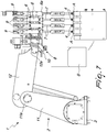
Figure 7 is a front elevation view of the station inFigure 4 in a first step of gripping the products; -
Figure 8 is a front elevation view of the station inFigure 4 in a second step of lifting the products; -
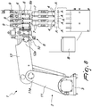
Figure 9 is a front elevation view of the station inFigure 4 in a third step of staggering the height of the products; -
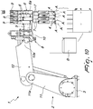
Figure 10 is a front elevation view of the station inFigure 4 in a fourth step of compaction of the products; -
Figure 11 is a front elevation view of the station inFigure 4 in a fifth step of realigning the height of the products; -
Figure 12 is a front elevation view of the station inFigure 4 in a sixth step of moving the compacted and realigned products; -
Figure 13 is a front elevation view of the station inFigure 4 in a seventh step of delivering the products to a specific packing box. - With reference to the figures, the
reference numeral 1 generally designates a pickup and delivery station for products A. - The products A can preferably be constituted by capsules for espresso coffee machines; however, the possibility is not ruled out of using the
station 1 for picking up and delivering other products with a mutually complementary shape and/or products that are arranged alternately upright and upturned. - The products are then inserted by the
station 1 into a box B, of suitable shape and size for containing a specific set of products A and/or of multiple groups of products A (delivered during successive and consecutive operations of the station 1). - The
station 1 comprises amovement arm 2 that is articulated with respect to afixed frame 3. - The
arm 2 supports, at its free end, at least one respective grip means 4 for at least one product A. - The free end of the
arm 2 in turn comprises at least onetrack 5 for at least twocarriages 6 for supporting at least onerespective shaft 7 that supports the grip means 4. - A first
linear actuator 8, which is substantially parallel to the direction of thetrack 5, is associated with one of thecarriages 6 for its movement along thetrack 5, from a configuration of separation from the othercontiguous carriage 6 to a configuration of proximity thereto. - Each at least one
shaft 7 of a respective grip means 4 is coupled to a secondlinear actuator 9 that is perpendicular to thefirst actuator 8 for the offset of the respective grip means 4 with respect to the contiguous ones. - According to the invention, the
tracks 5 are a plurality, are mutually side by side and are parallel, so as to define respective guide lanes for defined series ofcarriages 6 which can slide independently on each one of them. - It is convenient to note that each
track 5 comprises plurality ofcarriages 6 which can slide: thecarriage 6a, i.e. the farthest one from the end of the articulatedarm 2, is fixed on the track 5 (integral with it) so as to constitute a stroke limiter for theother carriages 6 that are present on thattrack 5. - In this manner a pushing action exerted by the
first actuator 8 determines the compaction (mutual approach) of the carriages 6 (and thus also of the grip means 4 that are integral therewith) into abutment against the fixedcarriage 6a, which is arranged substantially at the end of thetrack 5. - More specifically, the first
linear actuator 8 in such case comprises a rack-and-pinion assembly 10: the pinion is keyed to the shaft of a movement motor that is controlled by an adapted control and management unit; therack 10, on the other hand, is integral with thecarriage 6 that is closest to the end of the arm 2 (i.e., thecarriage 6 that is closest to the rack 10). - The rotation of the motor determines the advancement/retraction of the
rack 10, with consequent movement of thecarriage 6 associated therewith. - The
other carriages 6 which can slide on thesame track 5 will follow the movements of the one that was actuated by therack 10 according to the presence of adapted deviation and transmission elements, or according to the presence of elastic elements interposed betweencontiguous carriages 6. - In any case the stroke limiter reference point will always be constituted by the
fixed carriage 6a. - The second
linear actuator 9 is instead constituted by a cylinder, of type preferably selected from between pneumatic and hydraulic. - Of particular interest is the embodiment that involves the adoption of a pneumatic cylinder as the second linear actuator.
- The
shaft 7 is thus integral with the movable stem of thepneumatic cylinder 9, thus transmitting the movements imparted by thecylinder 9 to the grip means 4 arranged at its end, in order to vary the height thereof. - Generally, a respective second
linear actuator 9 for the longitudinal translation of theshaft 7, with consequent height variation of the respective grip means 4, is interposed between eachrespective carriage 6 and eachshaft 7 of each grip means 4 that is present thereon. - It should furthermore be noted that the grip means 4 comprises at least one sucker which is connected, by way of respective ducts, to centralized controlled suction means; at least one section of such ducts comprises at least one valve that is controlled by a control and management unit for the adjustment of the connection and disconnection times of the sucker to and from the suction means.
- In fact it is necessary to have steps in which the suction means are directly connected to the sucker (which will then be adapted to lift at least one respective product A) and steps in which the sucker is disconnected (and thus prevented from supporting a product A).
- The
movement arm 2 articulated to afixed frame 3 comprises, according to an embodiment that is particularly efficient and is simple to implement, afirst beam 11 that is pivoted to theframe 3, asecond beam 12 that is pivoted to theend 11a of thefirst beam 11, and a supporting bracket 13 for the at least onetrack 5 which is coupled rotatably to theend 12a of thesecond beam 12. - Movement elements are interposed between the
frame 3 and thefirst beam 11, between thesecond beam 12 and thefirst beam 11 and between the bracket 13 and thesecond beam 12, and are controlled by the control and management unit that controls the entire device, in order to actuate the mutual rotations of such components. - In a preferred embodiment, which conforms to what is shown in the accompanying figures, the
tracks 5 are mutually side by side on the bracket 13 according to groupings that comprise a predefined number ofequidistant tracks 5. - The bracket 13 comprises preferably at least two side-by-side groupings, which are mutually separated by empty spaces: this makes it possible to define a number of sets of grip means 6 that will operate simultaneously to pick up and compact (or nest) the products A.
- In particular a first set of grip means 4 could pick up respective products A, compact (nest) them and insert them into a specific box B.
- A second set could then execute the same operation, thus depositing a second layer of products A into the box B. The number of superimposed layers will be such as to ensure that the box B is completely filled.
- Operation of the
station 1 is the following. - The
arm 2 brings the grip means 4 proximate to and in alignment with respective products A that are present on a gathering surface on which they are neatly arranged. - The controlled valves activate the suction means and the suckers of the grip means 4 couple stably to the surface facing thereto of the product A (first step of gripping, shown in the accompanying
Figure 7 ). - The
arm 2 will lift the products A (second step of lifting, shown in the accompanyingFigure 8 ). - Thanks to the second actuators 9 (which are constituted by pneumatic cylinders in the preferred embodiment) it is then possible to stagger the products A, by staggering the grip means 4 by way of varying the height of some of the shafts 7 (third step of staggering the height, shown in the accompanying
Figure 9 ). - It should be noted that the staggering described in the previous paragraph is obtained by generating a variation in the height of alternate grip means 4: the criterion with which the grip means 4 will be raised, i.e. alternating with each other, is such that each grip means 4 will end up at a different height with respect to the contiguous ones (both longitudinally and transversely).
- The
first actuators 8 then bring thecarriages 6 mutually closer together, with consequent compaction of the products A held by the grip means 4 (fourth step of compaction, or nesting, shown in the accompanyingFigure 10 ). - It should furthermore be noted that the compaction is preferably bidirectional: the
second actuators 9, in an embodiment that is particularly efficient and functional, in fact also comprise arail 8a along which thetracks 5 can slide transversely in order to bring the grip means 4 closer transversely as well during the compaction. - Therefore it can be seen that the grip means 4 undergo a mutual approach in the longitudinal direction thanks to the movement of the
carriages 6 on thetracks 5 and a mutual approach in the transverse direction thanks to the movement of thetracks 5 on therail 8a. - Obviously the
rail 8a comprises respective controlled movement motors for managing the compaction of thetracks 5 which can slide thereupon. - The controlled movement motors can include a motor element that is associated with a drive cam that is coupled to the various different tracks 5: the possibility is not excluded of adopting any other type of conventional movement motor.
- The
second actuators 9 thus eliminate the staggering of the grip means 4 (fifth step of realigning the compacted products, shown in the accompanyingFigure 11 ). - The
arm 2 at this point transfers the aligned and compacted products A to above of the box B (sixth step of moving the products A, shown in the accompanyingFigure 12 ). - Then comes the delivery, transfer, of the products A to the box B (inside the box B proper) while keeping them compacted in order to ensure a minimization of their overall space occupation which will allow a greater ease of insertion into the box B (seventh step of delivering the products A, shown in the accompanying
Figure 13 ). - It should be noted that the protection of the present invention also covers a
machine 14 for boxing products A which comprises aline 15 for the supply and sorting of products A on agathering surface 16 and at least oneconveyance line 17 of boxes B, arranged to the side of thegathering surface 16. - Arranged externally to the
conveyance line 17 of boxes B is astation 1 for picking up products A from thesurface 16 and subsequently inserting them into a box B that is present on theconveyance line 17. - The
station 1 comprises amovement arm 2 that is articulated with respect to a fixedframe 3. - The
arm 2 supports, at its free end, at least one respective grip means 4 for at least one product A. - The free end of the
arm 2 comprises at least onetrack 5 for at least twocarriages 6 for supporting at least onerespective shaft 7 that supports a grip means 4. - A first
linear actuator 8, which is substantially parallel to the direction of thetrack 5, is associated with one of thecarriages 6 for its movement along thetrack 5, from a configuration of separation from theother carriage 6 to a configuration of proximity thereto. - At least one
shaft 7 of a grip means 4 is preferably coupled to a secondlinear actuator 9 that is perpendicular to thefirst actuator 8 for the offset of the respective grip means 4 with respect to the contiguous ones. - Advantageously the present invention solves the problems explained previously, by providing a pickup and
delivery station 1 for products A which is simple and adapted to ensure high performance levels in terms of packaging speed (also with regard to the possibility of making successive, overlapped layers of products A in a single box B). - Effectively the
station 1 is simple to manage and maintain: in fact it is constituted by unrelated components that facilitate substitution operations and which, in the event of malfunction, do not result in the overall outage of the station (but only a possible reduction in performance). - Profitably the
station 1 is versatile and adapted to pack the products A in boxes of various different formats: in fact it is possible to reconfigure the groupings oftracks 5 in order to adapt them to the specific dimensions of the box B present on theline 17. - The invention, thus conceived, is susceptible of numerous modifications and variations, all of which are within the scope of the appended claims; moreover, all the details may be substituted by other, technically equivalent elements.
- In the embodiments illustrated, individual characteristics shown in relation to specific examples may in reality be interchanged with other, different characteristics, existing in other embodiments.
- In practice, the materials employed, as well as the dimensions, may be any according to requirements and to the state of the art.
- The content of Italian patent application no.
BO2013A000643 - Where the technical features mentioned in any claim are followed by reference numerals and/or signs, those reference numerals and/or signs have been included for the sole purpose of increasing the intelligibility of the claims and accordingly, such reference numerals and/or signs do not have any limiting effect on the interpretation of each element identified by way of example by such reference numerals and/or signs.
Claims (7)
- A pickup and delivery station for products (A), of the type comprising a movement arm (2) that is articulated with respect to a fixed frame (3) and supports, at its free end, at least one respective grip means (4) for at least one product (A), said free end of said arm (2) comprising at least one track (5) for at least two carriages (6) for supporting at least one respective shaft (7) that supports said grip means (4), a first linear actuator (8), which is substantially parallel to the direction of said track (5), being associated with one of said carriages (6) for its movement along said track (5), from a configuration of separation from the other carriage (6) to a configuration of proximity thereto, the at least one said shaft (7) of a respective grip means (4) being coupled to a second linear actuator (9), that is perpendicular to the first one, for the offset of the respective grip means (4) with respect to the contiguous ones, each second actuator (9) being adapted to stagger the height of contiguous grip means (4) with which products (A) are united, by way of a variation of height of the respective shafts (7), each first actuator (8) being adapted to bring carriages (6) mutually closer, with consequent compaction of the contiguous products (A), which are held by the grip means (4) at different heights, thus defining a group of products (A) that is compacted/nested, having a smaller outline than the outline of a same number of products (A) that are simply arranged side by side, characterised in that said tracks (5) are a plurality and are mutually side by side and parallel wherein each track (5) comprises a plurality of sliding carriages (6), the carriage (6a) that lies furthest from said end of said arm (2) being fixed on said track (5) so as to constitute a stroke limiter for the other carriages (6) that are present on said track (5), a respective second linear actuator (9) for the longitudinal translation of said shaft (7), with consequent height variation of the respective grip means (4), is interposed between a carriage (6) and each respective shaft (7) of each grip means (4) that is present thereon, with consequent height variation of the respective grip means (4) between a first configuration of coplanarity of all of the grip means (4) and a second configuration of height variation of each grip means (4) with respect to the contiguous ones, in both a longitudinal direction and a transverse direction, and further comprising a rail (8a) along which said tracks (5) can slide transversely in order to bring said grip means (4) closer transversely, the rail (8a) comprising respective controlled movement motors for managing the compaction of said tracks (5) slidable thereon.
- The station according to claim 1, characterized in that said first linear actuator (8) comprises a rack-and-pinion assembly (10), said pinion being keyed to the shaft of a movement motor that is controlled by an adapted control and management unit, said rack-and-pinion (10) being integral with the carriage (6) that lies closest to the end of said arm (2).
- The station according to claim 1, characterized in that said second linear actuator (9) is constituted by a cylinder of a type preferably selected from between pneumatic and hydraulic.
- The station according to one or more of the preceding claims, characterized in that said grip means (4) comprises at least one sucker which is connected, by way of respective ducts, to centralized controlled suction means, at least one section of said ducts comprising at least one valve that is controlled by a control and management unit for the adjustment of the connection and disconnection times of said sucker to and from said suction means.
- The station according to one or more of the preceding claims, characterized in that said movement arm (2) articulated to a fixed frame (3) comprises a first beam (11) that is pivoted to said frame (3), a second beam (12) that is pivoted to the end (11a) of said first beam (11), and a supporting bracket (13) for said at least one track (5) which is coupled rotatably to the end (12a) of said second beam (12), movement elements being interposed between said frame (3) and said first beam (11), between said second beam (12) and said first beam (11), and between said bracket (13) and said second beam (12) and being controlled by said control and management unit, in order to actuate the mutual rotations of said components.
- The station according to one or more of the preceding claims, characterized in that said tracks (5) are mutually side by side on said bracket (13) according to groupings that comprise a predefined number of equidistant tracks (5), said bracket (13) comprising at least two side-by-side groupings that are mutually separated by empty spaces.
- A machine for boxing products, comprising a line (15) for the supply and sorting of products (A) on a gathering surface (16) and at least one line (17) for conveying boxes (B), which is arranged to the side of said gathering surface (16), externally to said line (17) for conveying boxes (B) there being a station (1) according to claim 1 for picking up the products (A) from said surface (16) and subsequent insertion into a said box (B) that is present on said line (17) for conveying boxes (B).
Applications Claiming Priority (2)
| Application Number | Priority Date | Filing Date | Title |
|---|---|---|---|
| IT000643A ITBO20130643A1 (en) | 2013-11-25 | 2013-11-25 | COLLECTION STATION AND PRODUCT DELIVERY |
| PCT/IB2014/063702 WO2015075571A1 (en) | 2013-11-25 | 2014-08-05 | Pickup and delivery station for products |
Publications (2)
| Publication Number | Publication Date |
|---|---|
| EP3074314A1 EP3074314A1 (en) | 2016-10-05 |
| EP3074314B1 true EP3074314B1 (en) | 2018-11-14 |
Family
ID=50159330
Family Applications (1)
| Application Number | Title | Priority Date | Filing Date |
|---|---|---|---|
| EP14781272.1A Active EP3074314B1 (en) | 2013-11-25 | 2014-08-05 | Pickup and delivery station for products |
Country Status (5)
| Country | Link |
|---|---|
| US (1) | US10407195B2 (en) |
| EP (1) | EP3074314B1 (en) |
| CA (1) | CA2931605C (en) |
| IT (1) | ITBO20130643A1 (en) |
| WO (1) | WO2015075571A1 (en) |
Families Citing this family (20)
| Publication number | Priority date | Publication date | Assignee | Title |
|---|---|---|---|---|
| CN105411066A (en) * | 2015-11-20 | 2016-03-23 | 南京邮电大学 | Craft simulation flower discharging device and method |
| US11001400B2 (en) * | 2016-01-20 | 2021-05-11 | R.A Jones & Co. | Apparatus and methods for transferring continuously moving articles to continuously moving packages with intervening article grouping and group pitch adjustment |
| EP3381819A3 (en) * | 2017-03-27 | 2018-10-17 | Tetra Laval Holdings & Finance S.A. | Machine and method for producing packages of containers, in particular containers of pourable food products |
| IT201700047487A1 (en) * | 2017-05-03 | 2018-11-03 | Cavanna S P A Con Socio Unico | APPARATUS FOR THE ORDERED PACKAGING OF PRODUCTS IN ELEMENTS CONTAINERS AND ITS METHOD |
| IT201800001138A1 (en) * | 2018-01-17 | 2019-07-17 | Gd Spa | Method of feeding articles into a multi-line automatic machine and multi-line automatic machine |
| DE102018119575A1 (en) * | 2018-08-13 | 2020-02-13 | Krones Aktiengesellschaft | Process for transferring and inserting articles in outer packaging and device for carrying out the process |
| JP7145702B2 (en) * | 2018-09-07 | 2022-10-03 | 株式会社日立物流 | Robot system and its control method |
| CN109807085A (en) * | 2019-01-17 | 2019-05-28 | 安徽鸿森智能装备股份有限公司 | Spider sorting machine people |
| BR112022001661A2 (en) | 2019-07-30 | 2022-03-22 | Anheuser Busch Inbev Sa | Packaging apparatus for packaging packaging, method for packaging packaging and use of the apparatus |
| US11713147B2 (en) | 2019-07-30 | 2023-08-01 | Anheuser-Busch Inbev S.A. | Article picking and treating apparatus |
| MX2022001248A (en) | 2019-07-30 | 2022-05-10 | Anheuser Busch Inbev Sa | Denesting apparatus. |
| EP4003719A1 (en) | 2019-07-30 | 2022-06-01 | Anheuser-Busch InBev S.A. | Shaping tool for secondary packages |
| WO2021019012A1 (en) | 2019-07-30 | 2021-02-04 | Anheuser-Busch Inbev S.A. | Packaging apparatus |
| CN111067361B (en) * | 2019-12-31 | 2022-09-20 | 北京猎户星空科技有限公司 | Actuator, mechanical arm, intelligent catering preparation system and control method |
| CN111113058B (en) * | 2020-01-10 | 2025-04-11 | 江苏森蓝智能系统有限公司 | A copper busbar processing combined line body with two storage bins and three wires |
| JP6945246B2 (en) * | 2020-03-19 | 2021-10-06 | 株式会社イシダ | Article gripping system |
| EP4530206A3 (en) * | 2020-05-12 | 2025-06-04 | Uhlmann Pac-Systeme GmbH & Co. KG | Method and arrangement for transferring products |
| IT202000016654A1 (en) * | 2020-07-09 | 2022-01-09 | Gd Spa | DEVICE AND PROCEDURE FOR PACKAGING ITEMS TO BE PACKAGED |
| IT202000016630A1 (en) * | 2020-07-09 | 2022-01-09 | Gd Spa | TRANSFER DEVICE, ESPECIALLY FOR A PACKAGING MACHINE |
| DE102022109282B4 (en) | 2022-04-14 | 2024-06-06 | Gerhard Schubert Gesellschaft mit beschränkter Haftung | Packaging machine with a grouping device and method for producing single-layer groups of partially overlapping products |
Family Cites Families (17)
| Publication number | Priority date | Publication date | Assignee | Title |
|---|---|---|---|---|
| US3302967A (en) * | 1965-03-08 | 1967-02-07 | Hyster Co | Overhead load-handling apparatus |
| DK152906C (en) * | 1976-11-12 | 1988-12-05 | Hamba Maschf | DEVICE FOR DRAINING FOOD AND FOODS, SPECIFICALLY MILK PRODUCTS, IN BASKET SINGLE CONTAINERS |
| JPH0736920Y2 (en) * | 1987-06-18 | 1995-08-23 | 沖電気工業株式会社 | Holding interval adjusting device for electronic component transportation |
| US4892183A (en) * | 1988-08-25 | 1990-01-09 | Emhart Industries, Inc. | Take-out mechanism for a glass container forming machine |
| JP2547021Y2 (en) * | 1990-10-08 | 1997-09-03 | 株式会社アドバンテスト | IC test equipment |
| IT1271481B (en) * | 1993-10-11 | 1997-05-28 | Vortex Systems Srl | PRODUCT HANDLING DEVICE AND RELATED EQUIPMENT |
| KR970007078Y1 (en) * | 1994-06-03 | 1997-07-15 | Lg Semicon Co Ltd | Devices feeding apparatus |
| US5839769A (en) * | 1996-10-03 | 1998-11-24 | Kinetrix, Inc. | Expanding gripper with elastically variable pitch screw |
| KR100248704B1 (en) * | 1997-11-08 | 2000-03-15 | 정문술 | Device for adjusting spacing of semiconductor device in tester |
| US6439631B1 (en) * | 2000-03-03 | 2002-08-27 | Micron Technology, Inc. | Variable-pitch pick and place device |
| KR100456858B1 (en) * | 2002-12-18 | 2004-11-10 | 현대자동차주식회사 | A vertical shaft adjusting apparatus by multi steps at an attachment |
| IT1391405B1 (en) * | 2008-09-10 | 2011-12-23 | Fiordalba S R L | METHOD AND DEVICE FOR THE MANIPULATION OF FOOD PRODUCTS |
| IT1401851B1 (en) * | 2010-10-15 | 2013-08-28 | Marchesini Group Spa | METHOD FOR THE TRANSFER OF ARTICLES WITHDRAWAL FROM MORE CHANNELS TO A POWER SUPPLY LINE FOR A PACKAGING MACHINE |
| FR2971497B1 (en) * | 2011-02-15 | 2014-02-07 | Sidel Participations | TOOL FOR HANDLING AND COMBINING PRODUCTS AND METHOD FOR ADJUSTING IT. |
| ES2675796T5 (en) * | 2011-03-16 | 2023-04-21 | Cama1 S P A | Machine and method for packing articles in cardboard boxes |
| US9272849B2 (en) * | 2011-11-04 | 2016-03-01 | R. A Jones & Co. | Cup feeder |
| US9611102B2 (en) * | 2012-10-26 | 2017-04-04 | Illinois Tool Works Inc. | Laning robot systems and methods |
-
2013
- 2013-11-25 IT IT000643A patent/ITBO20130643A1/en unknown
-
2014
- 2014-08-05 CA CA2931605A patent/CA2931605C/en active Active
- 2014-08-05 EP EP14781272.1A patent/EP3074314B1/en active Active
- 2014-08-05 US US15/039,237 patent/US10407195B2/en active Active
- 2014-08-05 WO PCT/IB2014/063702 patent/WO2015075571A1/en not_active Ceased
Non-Patent Citations (1)
| Title |
|---|
| None * |
Also Published As
| Publication number | Publication date |
|---|---|
| ITBO20130643A1 (en) | 2015-05-26 |
| US20170036794A1 (en) | 2017-02-09 |
| CA2931605C (en) | 2022-01-25 |
| EP3074314A1 (en) | 2016-10-05 |
| WO2015075571A1 (en) | 2015-05-28 |
| US10407195B2 (en) | 2019-09-10 |
| CA2931605A1 (en) | 2015-05-28 |
Similar Documents
| Publication | Publication Date | Title |
|---|---|---|
| CA2931605C (en) | Pickup and delivery station for products | |
| RU2501723C2 (en) | Packaging machine and method of packaging products | |
| US11447280B2 (en) | Food product handling device, system, and related methods | |
| CN102811910B (en) | Method and machine for overpackaging articles to form lots of articles, of the kind including a plurality of articles and a cardboard overpackage | |
| EP2931636B1 (en) | Apparatus for sorting objects | |
| EP1803665A1 (en) | Pick up head for a product transfer device and method for transferring products | |
| US10858204B2 (en) | Sliding layer gripping device and relative layer transfer method | |
| EP4003845B1 (en) | An article picking and treating apparatus | |
| US10350769B2 (en) | Food product handling device, system, and related methods | |
| CN102530281A (en) | Method for packaging gift packs | |
| CN104487348A (en) | Packaging system | |
| CN115649877A (en) | Automatic equipment of putting things in good order of book type box | |
| CN116867719A (en) | Product handling equipment, systems and related methods | |
| CN106467182B (en) | Device for inserting a valve bag and method of operation | |
| ITRE20010037A1 (en) | AUTOMATIC LABEL APPLICATOR WITHOUT GLUE | |
| EP3453653B1 (en) | End of line pick and place unit | |
| CN216707536U (en) | But quick displacement connecting rod formula case packer manipulator | |
| EP2886470B1 (en) | Transfer device and method for transferring flexible containers | |
| CN207998009U (en) | For using the film of retractility to tie up the packaging facilities of commodity | |
| CN220115624U (en) | Automatic box separating device of stacker | |
| EP2607276B1 (en) | Apparatus and method for feeding paper blanks and similar flat objects | |
| CN206654237U (en) | The grasping mechanism of recrater | |
| HK1186449A (en) | Apparatus and method for feeding paper blanks and similar flat objects | |
| CN112693704A (en) | High-speed robot packing mechanism | |
| CN102069924A (en) | Mechanism in design modification |
Legal Events
| Date | Code | Title | Description |
|---|---|---|---|
| PUAI | Public reference made under article 153(3) epc to a published international application that has entered the european phase |
Free format text: ORIGINAL CODE: 0009012 |
|
| 17P | Request for examination filed |
Effective date: 20160616 |
|
| AK | Designated contracting states |
Kind code of ref document: A1 Designated state(s): AL AT BE BG CH CY CZ DE DK EE ES FI FR GB GR HR HU IE IS IT LI LT LU LV MC MK MT NL NO PL PT RO RS SE SI SK SM TR |
|
| AX | Request for extension of the european patent |
Extension state: BA ME |
|
| DAX | Request for extension of the european patent (deleted) | ||
| STAA | Information on the status of an ep patent application or granted ep patent |
Free format text: STATUS: EXAMINATION IS IN PROGRESS |
|
| 17Q | First examination report despatched |
Effective date: 20170503 |
|
| GRAP | Despatch of communication of intention to grant a patent |
Free format text: ORIGINAL CODE: EPIDOSNIGR1 |
|
| STAA | Information on the status of an ep patent application or granted ep patent |
Free format text: STATUS: GRANT OF PATENT IS INTENDED |
|
| INTG | Intention to grant announced |
Effective date: 20180530 |
|
| GRAS | Grant fee paid |
Free format text: ORIGINAL CODE: EPIDOSNIGR3 |
|
| GRAA | (expected) grant |
Free format text: ORIGINAL CODE: 0009210 |
|
| STAA | Information on the status of an ep patent application or granted ep patent |
Free format text: STATUS: THE PATENT HAS BEEN GRANTED |
|
| AK | Designated contracting states |
Kind code of ref document: B1 Designated state(s): AL AT BE BG CH CY CZ DE DK EE ES FI FR GB GR HR HU IE IS IT LI LT LU LV MC MK MT NL NO PL PT RO RS SE SI SK SM TR |
|
| REG | Reference to a national code |
Ref country code: CH Ref legal event code: EP Ref country code: AT Ref legal event code: REF Ref document number: 1064510 Country of ref document: AT Kind code of ref document: T Effective date: 20181115 |
|
| REG | Reference to a national code |
Ref country code: IE Ref legal event code: FG4D |
|
| REG | Reference to a national code |
Ref country code: DE Ref legal event code: R096 Ref document number: 602014036087 Country of ref document: DE |
|
| REG | Reference to a national code |
Ref country code: NL Ref legal event code: MP Effective date: 20181114 |
|
| REG | Reference to a national code |
Ref country code: LT Ref legal event code: MG4D |
|
| REG | Reference to a national code |
Ref country code: AT Ref legal event code: MK05 Ref document number: 1064510 Country of ref document: AT Kind code of ref document: T Effective date: 20181114 |
|
| PG25 | Lapsed in a contracting state [announced via postgrant information from national office to epo] |
Ref country code: LT Free format text: LAPSE BECAUSE OF FAILURE TO SUBMIT A TRANSLATION OF THE DESCRIPTION OR TO PAY THE FEE WITHIN THE PRESCRIBED TIME-LIMIT Effective date: 20181114 Ref country code: HR Free format text: LAPSE BECAUSE OF FAILURE TO SUBMIT A TRANSLATION OF THE DESCRIPTION OR TO PAY THE FEE WITHIN THE PRESCRIBED TIME-LIMIT Effective date: 20181114 Ref country code: BG Free format text: LAPSE BECAUSE OF FAILURE TO SUBMIT A TRANSLATION OF THE DESCRIPTION OR TO PAY THE FEE WITHIN THE PRESCRIBED TIME-LIMIT Effective date: 20190214 Ref country code: ES Free format text: LAPSE BECAUSE OF FAILURE TO SUBMIT A TRANSLATION OF THE DESCRIPTION OR TO PAY THE FEE WITHIN THE PRESCRIBED TIME-LIMIT Effective date: 20181114 Ref country code: AT Free format text: LAPSE BECAUSE OF FAILURE TO SUBMIT A TRANSLATION OF THE DESCRIPTION OR TO PAY THE FEE WITHIN THE PRESCRIBED TIME-LIMIT Effective date: 20181114 Ref country code: IS Free format text: LAPSE BECAUSE OF FAILURE TO SUBMIT A TRANSLATION OF THE DESCRIPTION OR TO PAY THE FEE WITHIN THE PRESCRIBED TIME-LIMIT Effective date: 20190314 Ref country code: NO Free format text: LAPSE BECAUSE OF FAILURE TO SUBMIT A TRANSLATION OF THE DESCRIPTION OR TO PAY THE FEE WITHIN THE PRESCRIBED TIME-LIMIT Effective date: 20190214 Ref country code: FI Free format text: LAPSE BECAUSE OF FAILURE TO SUBMIT A TRANSLATION OF THE DESCRIPTION OR TO PAY THE FEE WITHIN THE PRESCRIBED TIME-LIMIT Effective date: 20181114 Ref country code: LV Free format text: LAPSE BECAUSE OF FAILURE TO SUBMIT A TRANSLATION OF THE DESCRIPTION OR TO PAY THE FEE WITHIN THE PRESCRIBED TIME-LIMIT Effective date: 20181114 |
|
| PG25 | Lapsed in a contracting state [announced via postgrant information from national office to epo] |
Ref country code: AL Free format text: LAPSE BECAUSE OF FAILURE TO SUBMIT A TRANSLATION OF THE DESCRIPTION OR TO PAY THE FEE WITHIN THE PRESCRIBED TIME-LIMIT Effective date: 20181114 Ref country code: SE Free format text: LAPSE BECAUSE OF FAILURE TO SUBMIT A TRANSLATION OF THE DESCRIPTION OR TO PAY THE FEE WITHIN THE PRESCRIBED TIME-LIMIT Effective date: 20181114 Ref country code: RS Free format text: LAPSE BECAUSE OF FAILURE TO SUBMIT A TRANSLATION OF THE DESCRIPTION OR TO PAY THE FEE WITHIN THE PRESCRIBED TIME-LIMIT Effective date: 20181114 Ref country code: GR Free format text: LAPSE BECAUSE OF FAILURE TO SUBMIT A TRANSLATION OF THE DESCRIPTION OR TO PAY THE FEE WITHIN THE PRESCRIBED TIME-LIMIT Effective date: 20190215 Ref country code: PT Free format text: LAPSE BECAUSE OF FAILURE TO SUBMIT A TRANSLATION OF THE DESCRIPTION OR TO PAY THE FEE WITHIN THE PRESCRIBED TIME-LIMIT Effective date: 20190314 Ref country code: NL Free format text: LAPSE BECAUSE OF FAILURE TO SUBMIT A TRANSLATION OF THE DESCRIPTION OR TO PAY THE FEE WITHIN THE PRESCRIBED TIME-LIMIT Effective date: 20181114 |
|
| PG25 | Lapsed in a contracting state [announced via postgrant information from national office to epo] |
Ref country code: PL Free format text: LAPSE BECAUSE OF FAILURE TO SUBMIT A TRANSLATION OF THE DESCRIPTION OR TO PAY THE FEE WITHIN THE PRESCRIBED TIME-LIMIT Effective date: 20181114 Ref country code: DK Free format text: LAPSE BECAUSE OF FAILURE TO SUBMIT A TRANSLATION OF THE DESCRIPTION OR TO PAY THE FEE WITHIN THE PRESCRIBED TIME-LIMIT Effective date: 20181114 Ref country code: CZ Free format text: LAPSE BECAUSE OF FAILURE TO SUBMIT A TRANSLATION OF THE DESCRIPTION OR TO PAY THE FEE WITHIN THE PRESCRIBED TIME-LIMIT Effective date: 20181114 |
|
| REG | Reference to a national code |
Ref country code: DE Ref legal event code: R097 Ref document number: 602014036087 Country of ref document: DE |
|
| PG25 | Lapsed in a contracting state [announced via postgrant information from national office to epo] |
Ref country code: RO Free format text: LAPSE BECAUSE OF FAILURE TO SUBMIT A TRANSLATION OF THE DESCRIPTION OR TO PAY THE FEE WITHIN THE PRESCRIBED TIME-LIMIT Effective date: 20181114 Ref country code: EE Free format text: LAPSE BECAUSE OF FAILURE TO SUBMIT A TRANSLATION OF THE DESCRIPTION OR TO PAY THE FEE WITHIN THE PRESCRIBED TIME-LIMIT Effective date: 20181114 Ref country code: SM Free format text: LAPSE BECAUSE OF FAILURE TO SUBMIT A TRANSLATION OF THE DESCRIPTION OR TO PAY THE FEE WITHIN THE PRESCRIBED TIME-LIMIT Effective date: 20181114 Ref country code: SK Free format text: LAPSE BECAUSE OF FAILURE TO SUBMIT A TRANSLATION OF THE DESCRIPTION OR TO PAY THE FEE WITHIN THE PRESCRIBED TIME-LIMIT Effective date: 20181114 |
|
| PLBE | No opposition filed within time limit |
Free format text: ORIGINAL CODE: 0009261 |
|
| STAA | Information on the status of an ep patent application or granted ep patent |
Free format text: STATUS: NO OPPOSITION FILED WITHIN TIME LIMIT |
|
| 26N | No opposition filed |
Effective date: 20190815 |
|
| PG25 | Lapsed in a contracting state [announced via postgrant information from national office to epo] |
Ref country code: SI Free format text: LAPSE BECAUSE OF FAILURE TO SUBMIT A TRANSLATION OF THE DESCRIPTION OR TO PAY THE FEE WITHIN THE PRESCRIBED TIME-LIMIT Effective date: 20181114 |
|
| PG25 | Lapsed in a contracting state [announced via postgrant information from national office to epo] |
Ref country code: TR Free format text: LAPSE BECAUSE OF FAILURE TO SUBMIT A TRANSLATION OF THE DESCRIPTION OR TO PAY THE FEE WITHIN THE PRESCRIBED TIME-LIMIT Effective date: 20181114 |
|
| PG25 | Lapsed in a contracting state [announced via postgrant information from national office to epo] |
Ref country code: LI Free format text: LAPSE BECAUSE OF NON-PAYMENT OF DUE FEES Effective date: 20190831 Ref country code: MC Free format text: LAPSE BECAUSE OF FAILURE TO SUBMIT A TRANSLATION OF THE DESCRIPTION OR TO PAY THE FEE WITHIN THE PRESCRIBED TIME-LIMIT Effective date: 20181114 Ref country code: CH Free format text: LAPSE BECAUSE OF NON-PAYMENT OF DUE FEES Effective date: 20190831 Ref country code: LU Free format text: LAPSE BECAUSE OF NON-PAYMENT OF DUE FEES Effective date: 20190805 |
|
| REG | Reference to a national code |
Ref country code: BE Ref legal event code: MM Effective date: 20190831 |
|
| PG25 | Lapsed in a contracting state [announced via postgrant information from national office to epo] |
Ref country code: IE Free format text: LAPSE BECAUSE OF NON-PAYMENT OF DUE FEES Effective date: 20190805 |
|
| PG25 | Lapsed in a contracting state [announced via postgrant information from national office to epo] |
Ref country code: BE Free format text: LAPSE BECAUSE OF NON-PAYMENT OF DUE FEES Effective date: 20190831 |
|
| PG25 | Lapsed in a contracting state [announced via postgrant information from national office to epo] |
Ref country code: CY Free format text: LAPSE BECAUSE OF FAILURE TO SUBMIT A TRANSLATION OF THE DESCRIPTION OR TO PAY THE FEE WITHIN THE PRESCRIBED TIME-LIMIT Effective date: 20181114 |
|
| PG25 | Lapsed in a contracting state [announced via postgrant information from national office to epo] |
Ref country code: HU Free format text: LAPSE BECAUSE OF FAILURE TO SUBMIT A TRANSLATION OF THE DESCRIPTION OR TO PAY THE FEE WITHIN THE PRESCRIBED TIME-LIMIT; INVALID AB INITIO Effective date: 20140805 Ref country code: MT Free format text: LAPSE BECAUSE OF FAILURE TO SUBMIT A TRANSLATION OF THE DESCRIPTION OR TO PAY THE FEE WITHIN THE PRESCRIBED TIME-LIMIT Effective date: 20181114 |
|
| PG25 | Lapsed in a contracting state [announced via postgrant information from national office to epo] |
Ref country code: MK Free format text: LAPSE BECAUSE OF FAILURE TO SUBMIT A TRANSLATION OF THE DESCRIPTION OR TO PAY THE FEE WITHIN THE PRESCRIBED TIME-LIMIT Effective date: 20181114 |
|
| P01 | Opt-out of the competence of the unified patent court (upc) registered |
Effective date: 20230516 |
|
| PGFP | Annual fee paid to national office [announced via postgrant information from national office to epo] |
Ref country code: DE Payment date: 20250827 Year of fee payment: 12 |
|
| PGFP | Annual fee paid to national office [announced via postgrant information from national office to epo] |
Ref country code: IT Payment date: 20250827 Year of fee payment: 12 |
|
| PGFP | Annual fee paid to national office [announced via postgrant information from national office to epo] |
Ref country code: GB Payment date: 20250825 Year of fee payment: 12 |
|
| PGFP | Annual fee paid to national office [announced via postgrant information from national office to epo] |
Ref country code: FR Payment date: 20250822 Year of fee payment: 12 |