EP3073650B1 - Kombinierte vorrichtung für beleuchtung und optische kommunikation - Google Patents
Kombinierte vorrichtung für beleuchtung und optische kommunikation Download PDFInfo
- Publication number
- EP3073650B1 EP3073650B1 EP16162461.4A EP16162461A EP3073650B1 EP 3073650 B1 EP3073650 B1 EP 3073650B1 EP 16162461 A EP16162461 A EP 16162461A EP 3073650 B1 EP3073650 B1 EP 3073650B1
- Authority
- EP
- European Patent Office
- Prior art keywords
- lenses
- light
- light sources
- lighting
- zone
- Prior art date
- Legal status (The legal status is an assumption and is not a legal conclusion. Google has not performed a legal analysis and makes no representation as to the accuracy of the status listed.)
- Active
Links
Images


Classifications
-
- F—MECHANICAL ENGINEERING; LIGHTING; HEATING; WEAPONS; BLASTING
- F21—LIGHTING
- F21V—FUNCTIONAL FEATURES OR DETAILS OF LIGHTING DEVICES OR SYSTEMS THEREOF; STRUCTURAL COMBINATIONS OF LIGHTING DEVICES WITH OTHER ARTICLES, NOT OTHERWISE PROVIDED FOR
- F21V5/00—Refractors for light sources
- F21V5/007—Array of lenses or refractors for a cluster of light sources, e.g. for arrangement of multiple light sources in one plane
-
- F—MECHANICAL ENGINEERING; LIGHTING; HEATING; WEAPONS; BLASTING
- F21—LIGHTING
- F21V—FUNCTIONAL FEATURES OR DETAILS OF LIGHTING DEVICES OR SYSTEMS THEREOF; STRUCTURAL COMBINATIONS OF LIGHTING DEVICES WITH OTHER ARTICLES, NOT OTHERWISE PROVIDED FOR
- F21V14/00—Controlling the distribution of the light emitted by adjustment of elements
- F21V14/06—Controlling the distribution of the light emitted by adjustment of elements by movement of refractors
-
- H—ELECTRICITY
- H04—ELECTRIC COMMUNICATION TECHNIQUE
- H04B—TRANSMISSION
- H04B10/00—Transmission systems employing electromagnetic waves other than radio-waves, e.g. infrared, visible or ultraviolet light, or employing corpuscular radiation, e.g. quantum communication
- H04B10/11—Arrangements specific to free-space transmission, i.e. transmission through air or vacuum
- H04B10/114—Indoor or close-range type systems
- H04B10/1141—One-way transmission
-
- H—ELECTRICITY
- H04—ELECTRIC COMMUNICATION TECHNIQUE
- H04B—TRANSMISSION
- H04B10/00—Transmission systems employing electromagnetic waves other than radio-waves, e.g. infrared, visible or ultraviolet light, or employing corpuscular radiation, e.g. quantum communication
- H04B10/11—Arrangements specific to free-space transmission, i.e. transmission through air or vacuum
- H04B10/114—Indoor or close-range type systems
- H04B10/116—Visible light communication
-
- H—ELECTRICITY
- H04—ELECTRIC COMMUNICATION TECHNIQUE
- H04B—TRANSMISSION
- H04B10/00—Transmission systems employing electromagnetic waves other than radio-waves, e.g. infrared, visible or ultraviolet light, or employing corpuscular radiation, e.g. quantum communication
- H04B10/50—Transmitters
- H04B10/501—Structural aspects
- H04B10/502—LED transmitters
-
- F—MECHANICAL ENGINEERING; LIGHTING; HEATING; WEAPONS; BLASTING
- F21—LIGHTING
- F21Y—INDEXING SCHEME ASSOCIATED WITH SUBCLASSES F21K, F21L, F21S and F21V, RELATING TO THE FORM OR THE KIND OF THE LIGHT SOURCES OR OF THE COLOUR OF THE LIGHT EMITTED
- F21Y2105/00—Planar light sources
-
- F—MECHANICAL ENGINEERING; LIGHTING; HEATING; WEAPONS; BLASTING
- F21—LIGHTING
- F21Y—INDEXING SCHEME ASSOCIATED WITH SUBCLASSES F21K, F21L, F21S and F21V, RELATING TO THE FORM OR THE KIND OF THE LIGHT SOURCES OR OF THE COLOUR OF THE LIGHT EMITTED
- F21Y2105/00—Planar light sources
- F21Y2105/10—Planar light sources comprising a two-dimensional [2D] array of point-like light-generating elements
Definitions
- the present invention relates to the field of wireless communications and more particularly to the field of data transmissions based on the use of visible light.
- connection standards such as 4G, Wifi, Wimax or Bluetooth allow users to access all kinds of online services with a very good quality of service.
- connection standards such as 4G, Wifi, Wimax or Bluetooth allow users to access all kinds of online services with a very good quality of service.
- These technologies rely on the use of the electromagnetic spectrum to transmit the data.
- LiFi Light Fidelity
- VLC Vehicle Light Communication
- diodes adapted to transmit data in the visible light are arranged concentrically on a circular plate comprising a peripheral portion and a central portion, the center of the plate comprising a photosensitive area adapted to receive data transmitted in visible light.
- the patent application US 2008 / 215391A1 discloses a lighting device comprising a central lighting unit adapted to produce, for example by means of a lens, a light beam of determined size. Locations arranged around this central light source can accommodate interchangeable modules, such as a communication module.
- the device comprises a plate on which light sources are located. It may be for example a printed circuit board on which LEDs are implanted. Part of the light sources, for example those located in the center of the plate, is adapted to transmit data in the form of an optical signal. The other part of the light sources, located for example on the periphery of the tray, provides a conventional lighting function.
- the device further comprises a plurality of lenses arranged at least in front of the light sources adapted to transmit data.
- the lenses for the central portion may have different characteristics of the lenses for the peripheral portion to produce beams with different characteristics. The lenses are thus positioned to capture the light from the light sources and form a light beam whose characteristics depend on the lenses used.
- the light sources adapted for lighting alone may not have lenses and emit a diffused light that contributes to the ambient lighting, while the light from the light sources capable of transmitting data can be concentrated in a beam allowing to target a particular location.
- a single device according to the invention thus provides a satisfactory ambient lighting while ensuring optimal data transfer to a specific location.
- the device is such that the light sources are LEDs.
- the device can use LEDs for the lighting and data transmission function. LEDs are particularly suitable for data transmission because they are inexpensive, compact, consume little energy and have a high frequency light modulation capability allowing high transmission rates.
- Diverging lenses are arranged in the axis of the light sources so as to receive the light from the light sources or the first convergent lenses.
- the divergent lenses of the first set may have different characteristics from those of the second set.
- the device can thus emit two concentric light beams whose opening angles are different. In this way, the device can offer for example a first narrow beam for transmitting data to a specific location and a second a wider beam for ambient lighting.
- the first fixed convergent lenses associated with the light sources make it possible to concentrate the light emitted by the light sources towards the diverging lenses.
- the device is such that the first and second elements are movable in translation along an axis perpendicular to the plate.
- the first and second elements can thus be moved while remaining parallel to the plate on which the first and second sets of light sources are mounted. It is thus possible to adjust independently the distance between the first element adapted to the central zone and the light sources of the central zone and the distance between the second element adapted to the zone. peripheral and light sources of the peripheral area.
- the first and second elements are movable only by translation along an axis perpendicular to the plate supporting the light sources so as to preserve the alignment of the sources, the first convergent lenses and the diverging lenses.
- the device thus makes it possible to modify the characteristics of the beams emitted by the device by modifying the distance between the light source and the diverging lens.
- the device comprises a control mechanism adapted to apply a translation along an axis perpendicular to the plate to at least one of the sets of diverging lenses.
- the adjustment mechanism allows a user to adjust at least one of the light beams emitted by the device.
- the device may comprise a first wheel for adjusting the distance between the first set of diverging lenses and the light sources and a second wheel for adjusting the distance between the second set of diverging lenses and the light sources. The beams emitted by the device can thus be modified by a user.
- a user can increase or reduce the difference between the first element corresponding to the central zone and comprising light sources adapted to the data transmission and the first convergent lenses to obtain a lighting beam with a more or less large aperture angle.
- the Figures 1 to 4 represent, according to a particular embodiment, different elements constituting a lighting device and combined optical communication.
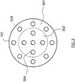
- a central zone 200 of the plate 100 supports LEDs adapted for the transmission of data in the optical spectrum.
- the LED 202 is able to transmit data by modulation of visible light.
- these LEDs are for example connected to a suitable modulation component, such as the microcontroller RL78 / I1A marketed by the company Renesas TM.
- the central portion 200 may include one or more LEDs.
- a peripheral zone 201 supports LEDs dedicated solely to lighting which are not suitable for transmitting data.
- the LED 203 shown on the figure 2 is not connected to a modulation component and is only used for lighting.
- the light sources for transmitting data are located in the peripheral zone while the LEDs participating only in the lighting are located in the central zone.
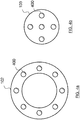
- a support 101 comprises a central zone 302 corresponding to the central zone 200 of the plate 100 and a peripheral zone 301 corresponding to the peripheral zone 201 of the plate 100.
- Convergent lenses such as the lens 304 are mounted at locations provided for this purpose. in the central zone 302. The location of the convergent lenses is determined so that each lens is positioned opposite a light source when the support 101 is positioned on the plate 100. Thus, the light emitted by a light source of the central zone of the plate 100 is received by a lens and redirected into a convergent beam.
- the convergent lenses are mounted at locations provided in the peripheral zone of the support 101.
- the location of the convergent lenses is determined so that each lens is positioned facing a light source when the support 101 is positioned on the plate 100.
- the light emitted by a light source from the peripheral zone of the plate 100 is received by a lens and redirected into a convergent beam.
- convergent lenses are mounted at locations in the central zone and at locations in the peripheral zone, the locations corresponding to the locations of the light sources when the support 101 is assembled with the plate 100.
- the lenses of the zone central and that of the peripheral area may have different optical characteristics.
- the support 101 and the plate 100 are a single piece, the convergent lenses then being directly integrated into the light sources.
- This may be for example LEDs with integrated optics or LEDs to which lenses are added using a lens holder.
- the device makes it possible to produce two concentric beams, one of which is used for transmitting data and the other for lighting only, the beams possibly having different characteristics such as, for example, a wide opening angle for the beam exterior dedicated to lighting only and a narrow aperture angle for the inner beam having a data transmission capability.
- a device may advantageously be mounted on a lamp holder of standard dimensions, such as for example a spot type lamp, so as to be easily installed at locations already provided for lighting.
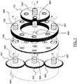
- the device further comprises a first element 103 adapted to the central zone comprising a first set of diverging lenses such as for example a lens 400, each of the lenses being disposed in the axis of a light source of the central zone, and a second element 102 adapted to the peripheral zone comprising a second set of diverging lenses, each of the lenses being disposed in the axis of a light source of the peripheral zone. It is thus possible to obtain two beams whose characteristics differ by positioning the elements 102 and 103 at distances respectively different from the support 101.
- the Figures 5a and 5b illustrate two examples of positioning a convergent lens and a lens divergent with respect to a light source S.
- the focal length of the diverging lenses 502 mounted on the elements 102 and 103 corresponds to half of the focal length convergent first lenses 501 of the support 101.
- the foci Fc and Fc 'of the lens 501 are located 10 mm from the optical center of the lens 501
- the foci Fd and Fd' of the lens 502 are located at 5 mm from the optical center of the lens 502.
- the convergent lens 501 is positioned so that the distance between the light source S and the focus Fc 'is identical to the distance between the focus Fc' and the optical center of the lens 501.
- the figure 5a illustrates a case where the diverging lens 502 is positioned between the optical center of the convergent lens 501 and its focus Fc.
- the light emitted by the source S produces a beam 503 having a wide opening angle at the exit of the diverging lens 502.
- the figure 5b illustrates a case where the diverging lens 502 is positioned so that the foci Fc and Fd 'are superimposed, i.e. the focus Fd is at a distance from the optical center of the lens 501 which is equal to the distance between the source S and the optical center of the lens 501.
- the light emitted by the source S produces a narrow and parallel beam 504 at the output of the diverging lens 502.
- the first and second elements 103 and 102 are movable in translation along an axis perpendicular to the plate. Since the elements 102 and 103 support the diverging lenses, it is thus possible to vary the distance between the convergent lenses of the support 101 and the divergent lenses of the elements 102 and 103 so as to modify the characteristics of the beams.
- the distance between the support 101 and the element 103 may be different from the distance between the support 101 and the element 102. In this way, it is possible to obtain two concentric beams of different characteristics at the output of the device.
- the device makes it possible to produce both a narrow beam from light sources suitable for data transmission and a wider beam from light sources intended for lighting alone.
- FIGS. 6a and 6b represent a schematic section of a device according to a particular embodiment of the invention.
- a support 101 comprising convergent lenses is positioned on a plate 100 on which light sources are mounted, the support being arranged so that each converging lens is positioned in front of a light source.
- the elements 102 and 103 respectively adapted to the peripheral zone and to the central zone of the device comprise diverging lenses, the light sources, convergent lenses and diverging lenses being aligned.
- the elements 102 and 103 are only movable in translation along an axis perpendicular to the plate 100, thus making it possible to vary the distance between the convergent lenses and the diverging lenses while maintaining the alignment of the sources, convergent lenses and diverging lenses.
- the figure 6a represents the device in a configuration in which the central element 103 has been translated relative to the support 101 so that the distance between the convergent lens support 101 and the central element 103 is greater than the distance between the support 101 and the peripheral element 102.
- This configuration allows to concentrate in a narrow beam the light emitted by the sources of the central zone.
- the figure 6b represents the device in a configuration in which the peripheral element 102 is translated relative to the support 101 so that the distance between the convergent lens support 101 and the peripheral element 102 supporting divergent lenses is greater than the distance between the support 101 and the central element 103.
- This configuration allows to illuminate a wide area from the light sources of the central portion while restricting the area illuminated by the sources of the peripheral portion.
- the maximum spacing between the support 101 and the elements 102 and 103 is reached when the focal points Fc of the convergent lenses supported by the support 101 are superimposed on the focal points Fd 'of the diverging lenses supported by the elements 102 and 103.
- the device then produces a rectilinear beam.
- the minimum spacing between the support 101 and the elements 102 and 103 is reached when the focal points of the divergent lenses supported by the elements 102 and 103 are superimposed on the optical centers of the first convergent lenses of the support 101.
- the figure 7 illustrates a nonlimiting example of a mechanism allowing a user to adjust the position of the elements 102 and 103 relative to the support 101 while maintaining the alignment of the light sources, convergent lenses and diverging lenses.
- the device comprises a circular support 100 on which are mounted light sources such as LEDs.
- the LEDs are divided into a first central zone and a second peripheral zone. Sources located in the central zone are adapted to transmit data by modulation of the emitted light.
- the light sources of the peripheral zone are, for example, LEDs having only a conventional lighting function.
- the device comprises a modulator adapted to modulate the light emitted by the LEDs of the central portion.
- the device further comprises a carrier type network interface, Wifi or for example Bluetooth.
- the data received via the network interface can be retransmitted by the LEDs of the central zone according to a protocol such as the LiFi protocol.
- the device may further comprise infrared LEDs adapted to transmit data in the non-visible light.
- the LEDs used in this example have a built-in convergent lens.
- the convergent lenses are mounted on a support such that the support 101 described with reference to the Figure 3a.
- the plate supporting the LEDs has 3 orifices, one orifice being positioned in the center of the plate, the two other orifices being diametrically opposed and located in the peripheral zone. These orifices are adapted to freely rotate the threaded rods 805, 806 and 807 therein.
- the device also comprises an element 102 in the form of a circular ring supporting diverging lenses.
- the element 102 has two diametrically opposed tapped orifices adapted to receive the threaded rods 805 and 806 so that they can be screwed in, the orifices being positioned to correspond to the orifices provided on the plate 100.
- the diverging lenses are arranged to correspond to the LEDs of the peripheral zone of the plate when the orifices of the plate 100 and the element 102 are superimposed.
- the device also comprises an element 103 corresponding to the central zone of the plate and having in its center a threaded orifice adapted to receive and screw a threaded rod 806.
- the element 103 comprises diverging lenses arranged to correspond to the LEDs of the part Central element of the plate 100.
- the element 102 further comprises a recess 809 for receiving a key 808 integral with the element 102 so as to make the elements 102 and 103 integral in rotation while allowing the elements 102 and 103 to move. relative to each other in a path perpendicular to the plate 100.
- the threaded rods 805, 806 and 807 extend inside a housing 804 by 3 toothed wheels 801, 802 and 803, the toothed wheels 801 and 803 flush with the outside of the housing so that they can be rotated by a user action, the gear being disposed at the center of the housing and in contact with the wheels 801 and 803.
- a clockwise rotation is applied to the wheel 801
- a counterclockwise rotation movement is transmitted to the central wheel 802
- the central wheel 802 in turn transmitting a clockwise rotational movement to the gear wheel 807.
- the toothed wheels 801, 802 and 803 are respectively integral with the threaded rods 805, 806 and 807.
- a rotation of a toothed wheel applies a rotation of the corresponding threaded rod.
- the rotation of the threaded rods 805 and 807 in the corresponding threaded holes on the element 102 makes it possible to apply a translation along a path perpendicular to the plate 100.
- the central wheel 802 being driven by the rotation of the wheels 801 and 803, the rotation of the threaded rod 806 in the threaded orifice of the element 103 makes it possible to apply to the latter a translation in a path perpendicular to the plate 100 in a direction opposite to the translation applied to the element 102.
- the device makes it possible, by a simple action of a user on a gear wheel flush with the housing, to simultaneously modify the characteristics of a light beam capable of transmitting data and those of a second beam of light intended to transmit data. to lighting.
- the figure 8 illustrates in a simplified and nonlimiting manner an assembly of electronic components adapted to provide a lighting function alone and a lighting function with data transmission according to a particular embodiment of the invention.
- the assembly can be integrated in a housing 900, for example in a bulb or a bulb base.
- the device comprises a first set of LEDs 901 connected to a power supply 904 (CONV).
- the device also comprises a second set of LEDs 902 connected to a modulation component (MOD) adapted to vary at high frequency the illumination provided by the LEDs 902 so as to transmit data through the visible light.
- MOD modulation component
- It can be a microcontroller capable of operating at high frequency and programmed for this purpose.
- the microcontroller RL78 / I1A marketed by the company Renesas TM can be adapted to such an implementation.
- the modulation component 903 is connected to the power supply 904.
- the LEDs 901 can only provide a lighting function while the LEDs 902 can, in addition to a lighting function, provide a data transmission function.
- the device may further comprise a communication module 905 (NW) adapted to receive and interpret data received via a communication network.
- the communication module can be a network interface implementing a powerline transmission technology (PLC for Line Carrier Current), a Bluetooth interface or Wifi.
- PLC Powerline transmission technology
- Wifi Wireless Fidelity
- the communication module 906 is connected to the modulation component 903. In this way, the device can retransmit in the visible light spectrum data received from a communication network, while providing a conventional lighting function via 901 LEDs.
- the device finds a particularly interesting use in the case of product lighting in a shop.
- the device can then be configured to produce a first focused light beam on the product and a wider second beam adapted for data transmission.
- the lighting beam thus makes it possible to highlight a product on a display stand while the larger data bundle enables the transmission of information relating to the product within a configurable perimeter around the product.
- the device may be configured to provide a wide illumination beam and a narrow data beam.
- This configuration is suitable, for example, for office lighting in an open space (“openspace”), providing both ambient lighting and data transmission over a restricted area.
- openspace open space
Landscapes
- Engineering & Computer Science (AREA)
- Physics & Mathematics (AREA)
- Electromagnetism (AREA)
- Computer Networks & Wireless Communication (AREA)
- Signal Processing (AREA)
- General Engineering & Computer Science (AREA)
- Optical Communication System (AREA)
- Non-Portable Lighting Devices Or Systems Thereof (AREA)
- Arrangement Of Elements, Cooling, Sealing, Or The Like Of Lighting Devices (AREA)
Claims (4)
- Beleuchtungsvorrichtung, umfassend mehrere Lichtquellen, die auf einer Platte (100) befestigt sind, dadurch gekennzeichnet, dass sie aufweist:- eine erste Anordnung von Lichtquellen (202), die in einem zentralen Bereich (200) der Platte angeordnet ist,- eine zweite Anordnung von Lichtquellen (203), die in einem Umfangsbereich (201) der Platte angeordnet ist,wobei die Lichtquellen von einer der Anordnungen für das Übertragen von Daten durch Modulation des sichtbaren Lichts geeignet sind, wobei jede der Lichtquellen von mindestens einer der Anordnungen mit mindestens einer ersten festen konvergierenden Linse (304) verbunden sind, die in der Achse der Lichtquelle angeordnet ist,
wobei die Vorrichtung dadurch gekennzeichnet ist, dass die Lichtquellen der anderen Anordnung nicht für das Übertragen von Daten durch Modulation des sichtbaren Lichts geeignet sind und dadurch, dass sie ferner parallel zu der Platte angeordnet und die Lichtquellen und ersten Linsen überlagernd aufweist:- ein erstes Element (103), das an den ersten zentralen Bereich angepasst ist, umfassend eine erste Anordnung von divergierenden Linsen, wobei jede der Linsen in der Achse einer Lichtquelle des zentralen Bereichs angeordnet ist, und- ein zweites Element (102), das an den ersten Umfangsbereich angepasst ist, umfassend eine zweite Anordnung von divergierenden Linsen, wobei jede der Linsen in der Achse einer Lichtquelle des Umfangsbereichs angeordnet ist. - Vorrichtung nach Anspruch 1, dadurch gekennzeichnet, dass die Lichtquellen LEDs sind.
- Vorrichtung nach einem der vorhergehenden Ansprüche, dadurch gekennzeichnet, dass die ersten und zweiten Elemente gemäß einer Achse, die senkrecht zu der Platte ist, translatorisch beweglich sind.
- Vorrichtung nach Anspruch 3, dadurch gekennzeichnet, dass sie einen Einstellmechanismus aufweist, der geeignet ist, um eine Translation gemäß einer Achse, die senkrecht zu der Platte ist, auf mindestens eine der Anordnung von divergierenden Linsen anzuwenden.
Applications Claiming Priority (1)
| Application Number | Priority Date | Filing Date | Title |
|---|---|---|---|
| FR1552604A FR3034270A1 (fr) | 2015-03-27 | 2015-03-27 | Dispositif d'eclairage et de communication optique combine |
Publications (2)
| Publication Number | Publication Date |
|---|---|
| EP3073650A1 EP3073650A1 (de) | 2016-09-28 |
| EP3073650B1 true EP3073650B1 (de) | 2018-07-04 |
Family
ID=53514319
Family Applications (1)
| Application Number | Title | Priority Date | Filing Date |
|---|---|---|---|
| EP16162461.4A Active EP3073650B1 (de) | 2015-03-27 | 2016-03-25 | Kombinierte vorrichtung für beleuchtung und optische kommunikation |
Country Status (3)
| Country | Link |
|---|---|
| US (1) | US10180239B2 (de) |
| EP (1) | EP3073650B1 (de) |
| FR (1) | FR3034270A1 (de) |
Families Citing this family (7)
| Publication number | Priority date | Publication date | Assignee | Title |
|---|---|---|---|---|
| EP3329616B1 (de) * | 2015-07-27 | 2019-03-27 | Signify Holding B.V. | Lichtemittierende vorrichtung zur erzeugung von licht mit eingebetteten informationen |
| FR3059500A1 (fr) * | 2016-11-29 | 2018-06-01 | Orange | Dispositif d'eclairage et de communication optique combines a visualisation du champ de communication |
| CN110290468B (zh) * | 2019-07-04 | 2020-09-22 | 英华达(上海)科技有限公司 | 虚拟隔音通信方法、装置、系统、电子设备、存储介质 |
| US12081265B2 (en) * | 2019-10-09 | 2024-09-03 | Signify Holding B.V. | Optical wireless communication system and device |
| DE102020206180A1 (de) * | 2020-05-15 | 2021-11-18 | Fraunhofer-Gesellschaft zur Förderung der angewandten Forschung e.V. | Augensichere optisch-drahtlose kommunikation |
| US12215854B2 (en) * | 2023-01-13 | 2025-02-04 | Abl Ip Holding, Llc | Multi-beam solid-state luminaire |
| CN116379382A (zh) * | 2023-04-18 | 2023-07-04 | 江西普照电器有限公司 | 一种照明设备 |
Family Cites Families (6)
| Publication number | Priority date | Publication date | Assignee | Title |
|---|---|---|---|---|
| US6548967B1 (en) * | 1997-08-26 | 2003-04-15 | Color Kinetics, Inc. | Universal lighting network methods and systems |
| EP1863203A1 (de) * | 2002-10-24 | 2007-12-05 | Nakagawa Laboratories, Inc. | Kommunikationsvorrichtung mit Beleuchtungslicht |
| US9100124B2 (en) * | 2007-05-24 | 2015-08-04 | Federal Law Enforcement Development Services, Inc. | LED Light Fixture |
| US20120121244A1 (en) * | 2010-11-15 | 2012-05-17 | Congruent Concepts, LLC | Variable focus illuminator |
| CN202065923U (zh) | 2011-04-13 | 2011-12-07 | 正屋(厦门)电子有限公司 | Led灯的光束调节结构 |
| DE202012013045U1 (de) * | 2011-10-23 | 2014-09-09 | Martin Professional A/S | Beleuchtungsvorrichtung mit mehrfarbigem Lichtstrahl |
-
2015
- 2015-03-27 FR FR1552604A patent/FR3034270A1/fr active Pending
-
2016
- 2016-03-22 US US15/077,774 patent/US10180239B2/en active Active
- 2016-03-25 EP EP16162461.4A patent/EP3073650B1/de active Active
Non-Patent Citations (1)
| Title |
|---|
| None * |
Also Published As
| Publication number | Publication date |
|---|---|
| FR3034270A1 (fr) | 2016-09-30 |
| EP3073650A1 (de) | 2016-09-28 |
| US10180239B2 (en) | 2019-01-15 |
| US20160281963A1 (en) | 2016-09-29 |
Similar Documents
| Publication | Publication Date | Title |
|---|---|---|
| EP3073650B1 (de) | Kombinierte vorrichtung für beleuchtung und optische kommunikation | |
| EP3549281B1 (de) | Vorrichtung zur beleuchtung und optischen kommunikation in kombination mit der ansicht des kommunikationsfeldes | |
| FR2748577A1 (fr) | Dispositif d'illumination de surface | |
| EP2799764B1 (de) | Beleuchtungsvorrichtung zur Bildung eines Lichtfleckdurchmessers und variabler Farbtemperatur | |
| FR2919709A1 (fr) | Lampe d'operation avec sources lumineuses reglables, capables de generer un champ lumineux de distribution gaussienne. | |
| EP3145280A1 (de) | Led-lampe mit regulierungsvorrichtung der leuchtkraft | |
| EP3210828B1 (de) | Beleuchtungssystem für den fahrzeuginnenraum eines kraftfahrzeugs | |
| EP2772680B1 (de) | Drehbares elektrisches Beleuchtungsgerät | |
| EP3239598B1 (de) | Drehbares leuchtmodul | |
| EP3238991A1 (de) | Drehbares beleuchtungsmodul | |
| EP3190335B1 (de) | Leuchtvorrichtung, die mit einem gekrümmten umwandlungselement der wellenlänge ausgestattet ist, und scheinwerfer, der eine solche leuchtvorrichtung umfasst | |
| EP2829790A2 (de) | Beleuchtungssystem mit Kombination eines weißen Lichts und eines andersfarbigen Lichts | |
| EP2060849B1 (de) | Beleuchtungsvorrichtung mit punktartigen Lichtquellen | |
| FR3016426A1 (fr) | Ampoule a led a angle de diffusion ajustable | |
| EP2710292B1 (de) | Medizinische beleuchtungsvorrichtung für eine bedieneinheit | |
| EP3081857A1 (de) | Medizinische beleuchtungsvorrichtung | |
| EP1590602A1 (de) | Beleuchtungsvorrichtung | |
| FR2680014A1 (fr) | Appareil photo a objectif zoom. | |
| FR3068110B1 (fr) | Module lumineux a eclairage variable | |
| BE1027317B1 (fr) | Dispositif lumineux pour véhicules prioritaires | |
| FR3006745A1 (fr) | Dispositif d'eclairage et/ou de signalisation bi-couleur, notamment pour vehicule automobile | |
| EP3104065B1 (de) | Signal- und/oder beleuchtungsvorrichtung eines kraftfahrzeugs | |
| FR3042587B1 (fr) | Collimateur optique a encombrement reduit pour generer une petite tache d'eclairage | |
| FR3047946A1 (fr) | Liseuse, notamment pour l'habitacle d'un vehicule automobile | |
| FR3048656A3 (fr) | Dispositif d'eclairage d'urgence pour vehicules |
Legal Events
| Date | Code | Title | Description |
|---|---|---|---|
| PUAI | Public reference made under article 153(3) epc to a published international application that has entered the european phase |
Free format text: ORIGINAL CODE: 0009012 |
|
| AK | Designated contracting states |
Kind code of ref document: A1 Designated state(s): AL AT BE BG CH CY CZ DE DK EE ES FI FR GB GR HR HU IE IS IT LI LT LU LV MC MK MT NL NO PL PT RO RS SE SI SK SM TR |
|
| AX | Request for extension of the european patent |
Extension state: BA ME |
|
| STAA | Information on the status of an ep patent application or granted ep patent |
Free format text: STATUS: REQUEST FOR EXAMINATION WAS MADE |
|
| 17P | Request for examination filed |
Effective date: 20170322 |
|
| RBV | Designated contracting states (corrected) |
Designated state(s): AL AT BE BG CH CY CZ DE DK EE ES FI FR GB GR HR HU IE IS IT LI LT LU LV MC MK MT NL NO PL PT RO RS SE SI SK SM TR |
|
| GRAP | Despatch of communication of intention to grant a patent |
Free format text: ORIGINAL CODE: EPIDOSNIGR1 |
|
| STAA | Information on the status of an ep patent application or granted ep patent |
Free format text: STATUS: GRANT OF PATENT IS INTENDED |
|
| INTG | Intention to grant announced |
Effective date: 20171109 |
|
| GRAS | Grant fee paid |
Free format text: ORIGINAL CODE: EPIDOSNIGR3 |
|
| GRAA | (expected) grant |
Free format text: ORIGINAL CODE: 0009210 |
|
| STAA | Information on the status of an ep patent application or granted ep patent |
Free format text: STATUS: THE PATENT HAS BEEN GRANTED |
|
| AK | Designated contracting states |
Kind code of ref document: B1 Designated state(s): AL AT BE BG CH CY CZ DE DK EE ES FI FR GB GR HR HU IE IS IT LI LT LU LV MC MK MT NL NO PL PT RO RS SE SI SK SM TR |
|
| REG | Reference to a national code |
Ref country code: GB Ref legal event code: FG4D Free format text: NOT ENGLISH |
|
| REG | Reference to a national code |
Ref country code: CH Ref legal event code: EP |
|
| REG | Reference to a national code |
Ref country code: AT Ref legal event code: REF Ref document number: 1015620 Country of ref document: AT Kind code of ref document: T Effective date: 20180715 |
|
| REG | Reference to a national code |
Ref country code: IE Ref legal event code: FG4D Free format text: LANGUAGE OF EP DOCUMENT: FRENCH |
|
| REG | Reference to a national code |
Ref country code: DE Ref legal event code: R096 Ref document number: 602016003886 Country of ref document: DE |
|
| REG | Reference to a national code |
Ref country code: NL Ref legal event code: MP Effective date: 20180704 |
|
| REG | Reference to a national code |
Ref country code: LT Ref legal event code: MG4D |
|
| REG | Reference to a national code |
Ref country code: AT Ref legal event code: MK05 Ref document number: 1015620 Country of ref document: AT Kind code of ref document: T Effective date: 20180704 |
|
| PG25 | Lapsed in a contracting state [announced via postgrant information from national office to epo] |
Ref country code: NL Free format text: LAPSE BECAUSE OF FAILURE TO SUBMIT A TRANSLATION OF THE DESCRIPTION OR TO PAY THE FEE WITHIN THE PRESCRIBED TIME-LIMIT Effective date: 20180704 |
|
| PG25 | Lapsed in a contracting state [announced via postgrant information from national office to epo] |
Ref country code: FI Free format text: LAPSE BECAUSE OF FAILURE TO SUBMIT A TRANSLATION OF THE DESCRIPTION OR TO PAY THE FEE WITHIN THE PRESCRIBED TIME-LIMIT Effective date: 20180704 Ref country code: PL Free format text: LAPSE BECAUSE OF FAILURE TO SUBMIT A TRANSLATION OF THE DESCRIPTION OR TO PAY THE FEE WITHIN THE PRESCRIBED TIME-LIMIT Effective date: 20180704 Ref country code: CZ Free format text: LAPSE BECAUSE OF FAILURE TO SUBMIT A TRANSLATION OF THE DESCRIPTION OR TO PAY THE FEE WITHIN THE PRESCRIBED TIME-LIMIT Effective date: 20180704 Ref country code: IS Free format text: LAPSE BECAUSE OF FAILURE TO SUBMIT A TRANSLATION OF THE DESCRIPTION OR TO PAY THE FEE WITHIN THE PRESCRIBED TIME-LIMIT Effective date: 20181104 Ref country code: AT Free format text: LAPSE BECAUSE OF FAILURE TO SUBMIT A TRANSLATION OF THE DESCRIPTION OR TO PAY THE FEE WITHIN THE PRESCRIBED TIME-LIMIT Effective date: 20180704 Ref country code: LT Free format text: LAPSE BECAUSE OF FAILURE TO SUBMIT A TRANSLATION OF THE DESCRIPTION OR TO PAY THE FEE WITHIN THE PRESCRIBED TIME-LIMIT Effective date: 20180704 Ref country code: BG Free format text: LAPSE BECAUSE OF FAILURE TO SUBMIT A TRANSLATION OF THE DESCRIPTION OR TO PAY THE FEE WITHIN THE PRESCRIBED TIME-LIMIT Effective date: 20181004 Ref country code: GR Free format text: LAPSE BECAUSE OF FAILURE TO SUBMIT A TRANSLATION OF THE DESCRIPTION OR TO PAY THE FEE WITHIN THE PRESCRIBED TIME-LIMIT Effective date: 20181005 Ref country code: NO Free format text: LAPSE BECAUSE OF FAILURE TO SUBMIT A TRANSLATION OF THE DESCRIPTION OR TO PAY THE FEE WITHIN THE PRESCRIBED TIME-LIMIT Effective date: 20181004 Ref country code: RS Free format text: LAPSE BECAUSE OF FAILURE TO SUBMIT A TRANSLATION OF THE DESCRIPTION OR TO PAY THE FEE WITHIN THE PRESCRIBED TIME-LIMIT Effective date: 20180704 Ref country code: SE Free format text: LAPSE BECAUSE OF FAILURE TO SUBMIT A TRANSLATION OF THE DESCRIPTION OR TO PAY THE FEE WITHIN THE PRESCRIBED TIME-LIMIT Effective date: 20180704 |
|
| PG25 | Lapsed in a contracting state [announced via postgrant information from national office to epo] |
Ref country code: AL Free format text: LAPSE BECAUSE OF FAILURE TO SUBMIT A TRANSLATION OF THE DESCRIPTION OR TO PAY THE FEE WITHIN THE PRESCRIBED TIME-LIMIT Effective date: 20180704 Ref country code: ES Free format text: LAPSE BECAUSE OF FAILURE TO SUBMIT A TRANSLATION OF THE DESCRIPTION OR TO PAY THE FEE WITHIN THE PRESCRIBED TIME-LIMIT Effective date: 20180704 Ref country code: LV Free format text: LAPSE BECAUSE OF FAILURE TO SUBMIT A TRANSLATION OF THE DESCRIPTION OR TO PAY THE FEE WITHIN THE PRESCRIBED TIME-LIMIT Effective date: 20180704 Ref country code: HR Free format text: LAPSE BECAUSE OF FAILURE TO SUBMIT A TRANSLATION OF THE DESCRIPTION OR TO PAY THE FEE WITHIN THE PRESCRIBED TIME-LIMIT Effective date: 20180704 |
|
| REG | Reference to a national code |
Ref country code: DE Ref legal event code: R097 Ref document number: 602016003886 Country of ref document: DE |
|
| PG25 | Lapsed in a contracting state [announced via postgrant information from national office to epo] |
Ref country code: IT Free format text: LAPSE BECAUSE OF FAILURE TO SUBMIT A TRANSLATION OF THE DESCRIPTION OR TO PAY THE FEE WITHIN THE PRESCRIBED TIME-LIMIT Effective date: 20180704 Ref country code: EE Free format text: LAPSE BECAUSE OF FAILURE TO SUBMIT A TRANSLATION OF THE DESCRIPTION OR TO PAY THE FEE WITHIN THE PRESCRIBED TIME-LIMIT Effective date: 20180704 Ref country code: RO Free format text: LAPSE BECAUSE OF FAILURE TO SUBMIT A TRANSLATION OF THE DESCRIPTION OR TO PAY THE FEE WITHIN THE PRESCRIBED TIME-LIMIT Effective date: 20180704 |
|
| PLBE | No opposition filed within time limit |
Free format text: ORIGINAL CODE: 0009261 |
|
| STAA | Information on the status of an ep patent application or granted ep patent |
Free format text: STATUS: NO OPPOSITION FILED WITHIN TIME LIMIT |
|
| PG25 | Lapsed in a contracting state [announced via postgrant information from national office to epo] |
Ref country code: DK Free format text: LAPSE BECAUSE OF FAILURE TO SUBMIT A TRANSLATION OF THE DESCRIPTION OR TO PAY THE FEE WITHIN THE PRESCRIBED TIME-LIMIT Effective date: 20180704 Ref country code: SK Free format text: LAPSE BECAUSE OF FAILURE TO SUBMIT A TRANSLATION OF THE DESCRIPTION OR TO PAY THE FEE WITHIN THE PRESCRIBED TIME-LIMIT Effective date: 20180704 Ref country code: SM Free format text: LAPSE BECAUSE OF FAILURE TO SUBMIT A TRANSLATION OF THE DESCRIPTION OR TO PAY THE FEE WITHIN THE PRESCRIBED TIME-LIMIT Effective date: 20180704 |
|
| 26N | No opposition filed |
Effective date: 20190405 |
|
| PG25 | Lapsed in a contracting state [announced via postgrant information from national office to epo] |
Ref country code: SI Free format text: LAPSE BECAUSE OF FAILURE TO SUBMIT A TRANSLATION OF THE DESCRIPTION OR TO PAY THE FEE WITHIN THE PRESCRIBED TIME-LIMIT Effective date: 20180704 |
|
| PG25 | Lapsed in a contracting state [announced via postgrant information from national office to epo] |
Ref country code: MC Free format text: LAPSE BECAUSE OF FAILURE TO SUBMIT A TRANSLATION OF THE DESCRIPTION OR TO PAY THE FEE WITHIN THE PRESCRIBED TIME-LIMIT Effective date: 20180704 |
|
| REG | Reference to a national code |
Ref country code: CH Ref legal event code: PL |
|
| PG25 | Lapsed in a contracting state [announced via postgrant information from national office to epo] |
Ref country code: LU Free format text: LAPSE BECAUSE OF NON-PAYMENT OF DUE FEES Effective date: 20190325 |
|
| REG | Reference to a national code |
Ref country code: BE Ref legal event code: MM Effective date: 20190331 |
|
| PG25 | Lapsed in a contracting state [announced via postgrant information from national office to epo] |
Ref country code: IE Free format text: LAPSE BECAUSE OF NON-PAYMENT OF DUE FEES Effective date: 20190325 Ref country code: CH Free format text: LAPSE BECAUSE OF NON-PAYMENT OF DUE FEES Effective date: 20190331 Ref country code: LI Free format text: LAPSE BECAUSE OF NON-PAYMENT OF DUE FEES Effective date: 20190331 |
|
| PG25 | Lapsed in a contracting state [announced via postgrant information from national office to epo] |
Ref country code: BE Free format text: LAPSE BECAUSE OF NON-PAYMENT OF DUE FEES Effective date: 20190331 |
|
| PG25 | Lapsed in a contracting state [announced via postgrant information from national office to epo] |
Ref country code: TR Free format text: LAPSE BECAUSE OF FAILURE TO SUBMIT A TRANSLATION OF THE DESCRIPTION OR TO PAY THE FEE WITHIN THE PRESCRIBED TIME-LIMIT Effective date: 20180704 |
|
| PG25 | Lapsed in a contracting state [announced via postgrant information from national office to epo] |
Ref country code: MT Free format text: LAPSE BECAUSE OF FAILURE TO SUBMIT A TRANSLATION OF THE DESCRIPTION OR TO PAY THE FEE WITHIN THE PRESCRIBED TIME-LIMIT Effective date: 20180704 Ref country code: PT Free format text: LAPSE BECAUSE OF FAILURE TO SUBMIT A TRANSLATION OF THE DESCRIPTION OR TO PAY THE FEE WITHIN THE PRESCRIBED TIME-LIMIT Effective date: 20181104 |
|
| PG25 | Lapsed in a contracting state [announced via postgrant information from national office to epo] |
Ref country code: CY Free format text: LAPSE BECAUSE OF FAILURE TO SUBMIT A TRANSLATION OF THE DESCRIPTION OR TO PAY THE FEE WITHIN THE PRESCRIBED TIME-LIMIT Effective date: 20180704 |
|
| PG25 | Lapsed in a contracting state [announced via postgrant information from national office to epo] |
Ref country code: HU Free format text: LAPSE BECAUSE OF FAILURE TO SUBMIT A TRANSLATION OF THE DESCRIPTION OR TO PAY THE FEE WITHIN THE PRESCRIBED TIME-LIMIT; INVALID AB INITIO Effective date: 20160325 |
|
| PG25 | Lapsed in a contracting state [announced via postgrant information from national office to epo] |
Ref country code: MK Free format text: LAPSE BECAUSE OF FAILURE TO SUBMIT A TRANSLATION OF THE DESCRIPTION OR TO PAY THE FEE WITHIN THE PRESCRIBED TIME-LIMIT Effective date: 20180704 |
|
| PGFP | Annual fee paid to national office [announced via postgrant information from national office to epo] |
Ref country code: GB Payment date: 20260219 Year of fee payment: 11 |
|
| PGFP | Annual fee paid to national office [announced via postgrant information from national office to epo] |
Ref country code: DE Payment date: 20260219 Year of fee payment: 11 |
|
| PGFP | Annual fee paid to national office [announced via postgrant information from national office to epo] |
Ref country code: FR Payment date: 20260220 Year of fee payment: 11 |