EP3073650B1 - Combined lighting and optical communication device - Google Patents
Combined lighting and optical communication device Download PDFInfo
- Publication number
- EP3073650B1 EP3073650B1 EP16162461.4A EP16162461A EP3073650B1 EP 3073650 B1 EP3073650 B1 EP 3073650B1 EP 16162461 A EP16162461 A EP 16162461A EP 3073650 B1 EP3073650 B1 EP 3073650B1
- Authority
- EP
- European Patent Office
- Prior art keywords
- lenses
- light
- light sources
- lighting
- zone
- Prior art date
- Legal status (The legal status is an assumption and is not a legal conclusion. Google has not performed a legal analysis and makes no representation as to the accuracy of the status listed.)
- Active
Links
Images


Classifications
-
- F—MECHANICAL ENGINEERING; LIGHTING; HEATING; WEAPONS; BLASTING
- F21—LIGHTING
- F21V—FUNCTIONAL FEATURES OR DETAILS OF LIGHTING DEVICES OR SYSTEMS THEREOF; STRUCTURAL COMBINATIONS OF LIGHTING DEVICES WITH OTHER ARTICLES, NOT OTHERWISE PROVIDED FOR
- F21V5/00—Refractors for light sources
- F21V5/007—Array of lenses or refractors for a cluster of light sources, e.g. for arrangement of multiple light sources in one plane
-
- F—MECHANICAL ENGINEERING; LIGHTING; HEATING; WEAPONS; BLASTING
- F21—LIGHTING
- F21V—FUNCTIONAL FEATURES OR DETAILS OF LIGHTING DEVICES OR SYSTEMS THEREOF; STRUCTURAL COMBINATIONS OF LIGHTING DEVICES WITH OTHER ARTICLES, NOT OTHERWISE PROVIDED FOR
- F21V14/00—Controlling the distribution of the light emitted by adjustment of elements
- F21V14/06—Controlling the distribution of the light emitted by adjustment of elements by movement of refractors
-
- H—ELECTRICITY
- H04—ELECTRIC COMMUNICATION TECHNIQUE
- H04B—TRANSMISSION
- H04B10/00—Transmission systems employing electromagnetic waves other than radio-waves, e.g. infrared, visible or ultraviolet light, or employing corpuscular radiation, e.g. quantum communication
- H04B10/11—Arrangements specific to free-space transmission, i.e. transmission through air or vacuum
- H04B10/114—Indoor or close-range type systems
- H04B10/1141—One-way transmission
-
- H—ELECTRICITY
- H04—ELECTRIC COMMUNICATION TECHNIQUE
- H04B—TRANSMISSION
- H04B10/00—Transmission systems employing electromagnetic waves other than radio-waves, e.g. infrared, visible or ultraviolet light, or employing corpuscular radiation, e.g. quantum communication
- H04B10/11—Arrangements specific to free-space transmission, i.e. transmission through air or vacuum
- H04B10/114—Indoor or close-range type systems
- H04B10/116—Visible light communication
-
- H—ELECTRICITY
- H04—ELECTRIC COMMUNICATION TECHNIQUE
- H04B—TRANSMISSION
- H04B10/00—Transmission systems employing electromagnetic waves other than radio-waves, e.g. infrared, visible or ultraviolet light, or employing corpuscular radiation, e.g. quantum communication
- H04B10/50—Transmitters
- H04B10/501—Structural aspects
- H04B10/502—LED transmitters
-
- F—MECHANICAL ENGINEERING; LIGHTING; HEATING; WEAPONS; BLASTING
- F21—LIGHTING
- F21Y—INDEXING SCHEME ASSOCIATED WITH SUBCLASSES F21K, F21L, F21S and F21V, RELATING TO THE FORM OR THE KIND OF THE LIGHT SOURCES OR OF THE COLOUR OF THE LIGHT EMITTED
- F21Y2105/00—Planar light sources
-
- F—MECHANICAL ENGINEERING; LIGHTING; HEATING; WEAPONS; BLASTING
- F21—LIGHTING
- F21Y—INDEXING SCHEME ASSOCIATED WITH SUBCLASSES F21K, F21L, F21S and F21V, RELATING TO THE FORM OR THE KIND OF THE LIGHT SOURCES OR OF THE COLOUR OF THE LIGHT EMITTED
- F21Y2105/00—Planar light sources
- F21Y2105/10—Planar light sources comprising a two-dimensional array of point-like light-generating elements
Definitions
- the present invention relates to the field of wireless communications and more particularly to the field of data transmissions based on the use of visible light.
- connection standards such as 4G, Wifi, Wimax or Bluetooth allow users to access all kinds of online services with a very good quality of service.
- connection standards such as 4G, Wifi, Wimax or Bluetooth allow users to access all kinds of online services with a very good quality of service.
- These technologies rely on the use of the electromagnetic spectrum to transmit the data.
- LiFi Light Fidelity
- VLC Vehicle Light Communication
- diodes adapted to transmit data in the visible light are arranged concentrically on a circular plate comprising a peripheral portion and a central portion, the center of the plate comprising a photosensitive area adapted to receive data transmitted in visible light.
- the patent application US 2008 / 215391A1 discloses a lighting device comprising a central lighting unit adapted to produce, for example by means of a lens, a light beam of determined size. Locations arranged around this central light source can accommodate interchangeable modules, such as a communication module.
- the device comprises a plate on which light sources are located. It may be for example a printed circuit board on which LEDs are implanted. Part of the light sources, for example those located in the center of the plate, is adapted to transmit data in the form of an optical signal. The other part of the light sources, located for example on the periphery of the tray, provides a conventional lighting function.
- the device further comprises a plurality of lenses arranged at least in front of the light sources adapted to transmit data.
- the lenses for the central portion may have different characteristics of the lenses for the peripheral portion to produce beams with different characteristics. The lenses are thus positioned to capture the light from the light sources and form a light beam whose characteristics depend on the lenses used.
- the light sources adapted for lighting alone may not have lenses and emit a diffused light that contributes to the ambient lighting, while the light from the light sources capable of transmitting data can be concentrated in a beam allowing to target a particular location.
- a single device according to the invention thus provides a satisfactory ambient lighting while ensuring optimal data transfer to a specific location.
- the device is such that the light sources are LEDs.
- the device can use LEDs for the lighting and data transmission function. LEDs are particularly suitable for data transmission because they are inexpensive, compact, consume little energy and have a high frequency light modulation capability allowing high transmission rates.
- Diverging lenses are arranged in the axis of the light sources so as to receive the light from the light sources or the first convergent lenses.
- the divergent lenses of the first set may have different characteristics from those of the second set.
- the device can thus emit two concentric light beams whose opening angles are different. In this way, the device can offer for example a first narrow beam for transmitting data to a specific location and a second a wider beam for ambient lighting.
- the first fixed convergent lenses associated with the light sources make it possible to concentrate the light emitted by the light sources towards the diverging lenses.
- the device is such that the first and second elements are movable in translation along an axis perpendicular to the plate.
- the first and second elements can thus be moved while remaining parallel to the plate on which the first and second sets of light sources are mounted. It is thus possible to adjust independently the distance between the first element adapted to the central zone and the light sources of the central zone and the distance between the second element adapted to the zone. peripheral and light sources of the peripheral area.
- the first and second elements are movable only by translation along an axis perpendicular to the plate supporting the light sources so as to preserve the alignment of the sources, the first convergent lenses and the diverging lenses.
- the device thus makes it possible to modify the characteristics of the beams emitted by the device by modifying the distance between the light source and the diverging lens.
- the device comprises a control mechanism adapted to apply a translation along an axis perpendicular to the plate to at least one of the sets of diverging lenses.
- the adjustment mechanism allows a user to adjust at least one of the light beams emitted by the device.
- the device may comprise a first wheel for adjusting the distance between the first set of diverging lenses and the light sources and a second wheel for adjusting the distance between the second set of diverging lenses and the light sources. The beams emitted by the device can thus be modified by a user.
- a user can increase or reduce the difference between the first element corresponding to the central zone and comprising light sources adapted to the data transmission and the first convergent lenses to obtain a lighting beam with a more or less large aperture angle.
- the Figures 1 to 4 represent, according to a particular embodiment, different elements constituting a lighting device and combined optical communication.
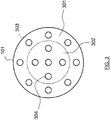
- a central zone 200 of the plate 100 supports LEDs adapted for the transmission of data in the optical spectrum.
- the LED 202 is able to transmit data by modulation of visible light.
- these LEDs are for example connected to a suitable modulation component, such as the microcontroller RL78 / I1A marketed by the company Renesas TM.
- the central portion 200 may include one or more LEDs.
- a peripheral zone 201 supports LEDs dedicated solely to lighting which are not suitable for transmitting data.
- the LED 203 shown on the figure 2 is not connected to a modulation component and is only used for lighting.
- the light sources for transmitting data are located in the peripheral zone while the LEDs participating only in the lighting are located in the central zone.
- a support 101 comprises a central zone 302 corresponding to the central zone 200 of the plate 100 and a peripheral zone 301 corresponding to the peripheral zone 201 of the plate 100.
- Convergent lenses such as the lens 304 are mounted at locations provided for this purpose. in the central zone 302. The location of the convergent lenses is determined so that each lens is positioned opposite a light source when the support 101 is positioned on the plate 100. Thus, the light emitted by a light source of the central zone of the plate 100 is received by a lens and redirected into a convergent beam.
- the convergent lenses are mounted at locations provided in the peripheral zone of the support 101.
- the location of the convergent lenses is determined so that each lens is positioned facing a light source when the support 101 is positioned on the plate 100.
- the light emitted by a light source from the peripheral zone of the plate 100 is received by a lens and redirected into a convergent beam.
- convergent lenses are mounted at locations in the central zone and at locations in the peripheral zone, the locations corresponding to the locations of the light sources when the support 101 is assembled with the plate 100.
- the lenses of the zone central and that of the peripheral area may have different optical characteristics.
- the support 101 and the plate 100 are a single piece, the convergent lenses then being directly integrated into the light sources.
- This may be for example LEDs with integrated optics or LEDs to which lenses are added using a lens holder.
- the device makes it possible to produce two concentric beams, one of which is used for transmitting data and the other for lighting only, the beams possibly having different characteristics such as, for example, a wide opening angle for the beam exterior dedicated to lighting only and a narrow aperture angle for the inner beam having a data transmission capability.
- a device may advantageously be mounted on a lamp holder of standard dimensions, such as for example a spot type lamp, so as to be easily installed at locations already provided for lighting.
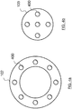
- the device further comprises a first element 103 adapted to the central zone comprising a first set of diverging lenses such as for example a lens 400, each of the lenses being disposed in the axis of a light source of the central zone, and a second element 102 adapted to the peripheral zone comprising a second set of diverging lenses, each of the lenses being disposed in the axis of a light source of the peripheral zone. It is thus possible to obtain two beams whose characteristics differ by positioning the elements 102 and 103 at distances respectively different from the support 101.
- the Figures 5a and 5b illustrate two examples of positioning a convergent lens and a lens divergent with respect to a light source S.
- the focal length of the diverging lenses 502 mounted on the elements 102 and 103 corresponds to half of the focal length convergent first lenses 501 of the support 101.
- the foci Fc and Fc 'of the lens 501 are located 10 mm from the optical center of the lens 501
- the foci Fd and Fd' of the lens 502 are located at 5 mm from the optical center of the lens 502.
- the convergent lens 501 is positioned so that the distance between the light source S and the focus Fc 'is identical to the distance between the focus Fc' and the optical center of the lens 501.
- the figure 5a illustrates a case where the diverging lens 502 is positioned between the optical center of the convergent lens 501 and its focus Fc.
- the light emitted by the source S produces a beam 503 having a wide opening angle at the exit of the diverging lens 502.
- the figure 5b illustrates a case where the diverging lens 502 is positioned so that the foci Fc and Fd 'are superimposed, i.e. the focus Fd is at a distance from the optical center of the lens 501 which is equal to the distance between the source S and the optical center of the lens 501.
- the light emitted by the source S produces a narrow and parallel beam 504 at the output of the diverging lens 502.
- the first and second elements 103 and 102 are movable in translation along an axis perpendicular to the plate. Since the elements 102 and 103 support the diverging lenses, it is thus possible to vary the distance between the convergent lenses of the support 101 and the divergent lenses of the elements 102 and 103 so as to modify the characteristics of the beams.
- the distance between the support 101 and the element 103 may be different from the distance between the support 101 and the element 102. In this way, it is possible to obtain two concentric beams of different characteristics at the output of the device.
- the device makes it possible to produce both a narrow beam from light sources suitable for data transmission and a wider beam from light sources intended for lighting alone.
- FIGS. 6a and 6b represent a schematic section of a device according to a particular embodiment of the invention.
- a support 101 comprising convergent lenses is positioned on a plate 100 on which light sources are mounted, the support being arranged so that each converging lens is positioned in front of a light source.
- the elements 102 and 103 respectively adapted to the peripheral zone and to the central zone of the device comprise diverging lenses, the light sources, convergent lenses and diverging lenses being aligned.
- the elements 102 and 103 are only movable in translation along an axis perpendicular to the plate 100, thus making it possible to vary the distance between the convergent lenses and the diverging lenses while maintaining the alignment of the sources, convergent lenses and diverging lenses.
- the figure 6a represents the device in a configuration in which the central element 103 has been translated relative to the support 101 so that the distance between the convergent lens support 101 and the central element 103 is greater than the distance between the support 101 and the peripheral element 102.
- This configuration allows to concentrate in a narrow beam the light emitted by the sources of the central zone.
- the figure 6b represents the device in a configuration in which the peripheral element 102 is translated relative to the support 101 so that the distance between the convergent lens support 101 and the peripheral element 102 supporting divergent lenses is greater than the distance between the support 101 and the central element 103.
- This configuration allows to illuminate a wide area from the light sources of the central portion while restricting the area illuminated by the sources of the peripheral portion.
- the maximum spacing between the support 101 and the elements 102 and 103 is reached when the focal points Fc of the convergent lenses supported by the support 101 are superimposed on the focal points Fd 'of the diverging lenses supported by the elements 102 and 103.
- the device then produces a rectilinear beam.
- the minimum spacing between the support 101 and the elements 102 and 103 is reached when the focal points of the divergent lenses supported by the elements 102 and 103 are superimposed on the optical centers of the first convergent lenses of the support 101.
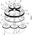
- the figure 7 illustrates a nonlimiting example of a mechanism allowing a user to adjust the position of the elements 102 and 103 relative to the support 101 while maintaining the alignment of the light sources, convergent lenses and diverging lenses.
- the device comprises a circular support 100 on which are mounted light sources such as LEDs.
- the LEDs are divided into a first central zone and a second peripheral zone. Sources located in the central zone are adapted to transmit data by modulation of the emitted light.
- the light sources of the peripheral zone are, for example, LEDs having only a conventional lighting function.
- the device comprises a modulator adapted to modulate the light emitted by the LEDs of the central portion.
- the device further comprises a carrier type network interface, Wifi or for example Bluetooth.
- the data received via the network interface can be retransmitted by the LEDs of the central zone according to a protocol such as the LiFi protocol.
- the device may further comprise infrared LEDs adapted to transmit data in the non-visible light.
- the LEDs used in this example have a built-in convergent lens.
- the convergent lenses are mounted on a support such that the support 101 described with reference to the Figure 3a.
- the plate supporting the LEDs has 3 orifices, one orifice being positioned in the center of the plate, the two other orifices being diametrically opposed and located in the peripheral zone. These orifices are adapted to freely rotate the threaded rods 805, 806 and 807 therein.
- the device also comprises an element 102 in the form of a circular ring supporting diverging lenses.
- the element 102 has two diametrically opposed tapped orifices adapted to receive the threaded rods 805 and 806 so that they can be screwed in, the orifices being positioned to correspond to the orifices provided on the plate 100.
- the diverging lenses are arranged to correspond to the LEDs of the peripheral zone of the plate when the orifices of the plate 100 and the element 102 are superimposed.
- the device also comprises an element 103 corresponding to the central zone of the plate and having in its center a threaded orifice adapted to receive and screw a threaded rod 806.
- the element 103 comprises diverging lenses arranged to correspond to the LEDs of the part Central element of the plate 100.
- the element 102 further comprises a recess 809 for receiving a key 808 integral with the element 102 so as to make the elements 102 and 103 integral in rotation while allowing the elements 102 and 103 to move. relative to each other in a path perpendicular to the plate 100.
- the threaded rods 805, 806 and 807 extend inside a housing 804 by 3 toothed wheels 801, 802 and 803, the toothed wheels 801 and 803 flush with the outside of the housing so that they can be rotated by a user action, the gear being disposed at the center of the housing and in contact with the wheels 801 and 803.
- a clockwise rotation is applied to the wheel 801
- a counterclockwise rotation movement is transmitted to the central wheel 802
- the central wheel 802 in turn transmitting a clockwise rotational movement to the gear wheel 807.
- the toothed wheels 801, 802 and 803 are respectively integral with the threaded rods 805, 806 and 807.
- a rotation of a toothed wheel applies a rotation of the corresponding threaded rod.
- the rotation of the threaded rods 805 and 807 in the corresponding threaded holes on the element 102 makes it possible to apply a translation along a path perpendicular to the plate 100.
- the central wheel 802 being driven by the rotation of the wheels 801 and 803, the rotation of the threaded rod 806 in the threaded orifice of the element 103 makes it possible to apply to the latter a translation in a path perpendicular to the plate 100 in a direction opposite to the translation applied to the element 102.
- the device makes it possible, by a simple action of a user on a gear wheel flush with the housing, to simultaneously modify the characteristics of a light beam capable of transmitting data and those of a second beam of light intended to transmit data. to lighting.
- the figure 8 illustrates in a simplified and nonlimiting manner an assembly of electronic components adapted to provide a lighting function alone and a lighting function with data transmission according to a particular embodiment of the invention.
- the assembly can be integrated in a housing 900, for example in a bulb or a bulb base.
- the device comprises a first set of LEDs 901 connected to a power supply 904 (CONV).
- the device also comprises a second set of LEDs 902 connected to a modulation component (MOD) adapted to vary at high frequency the illumination provided by the LEDs 902 so as to transmit data through the visible light.
- MOD modulation component
- It can be a microcontroller capable of operating at high frequency and programmed for this purpose.
- the microcontroller RL78 / I1A marketed by the company Renesas TM can be adapted to such an implementation.
- the modulation component 903 is connected to the power supply 904.
- the LEDs 901 can only provide a lighting function while the LEDs 902 can, in addition to a lighting function, provide a data transmission function.
- the device may further comprise a communication module 905 (NW) adapted to receive and interpret data received via a communication network.
- the communication module can be a network interface implementing a powerline transmission technology (PLC for Line Carrier Current), a Bluetooth interface or Wifi.
- PLC Powerline transmission technology
- Wifi Wireless Fidelity
- the communication module 906 is connected to the modulation component 903. In this way, the device can retransmit in the visible light spectrum data received from a communication network, while providing a conventional lighting function via 901 LEDs.
- the device finds a particularly interesting use in the case of product lighting in a shop.
- the device can then be configured to produce a first focused light beam on the product and a wider second beam adapted for data transmission.
- the lighting beam thus makes it possible to highlight a product on a display stand while the larger data bundle enables the transmission of information relating to the product within a configurable perimeter around the product.
- the device may be configured to provide a wide illumination beam and a narrow data beam.
- This configuration is suitable, for example, for office lighting in an open space (“openspace”), providing both ambient lighting and data transmission over a restricted area.
- openspace open space
Description
La présente invention se rapporte au domaine des communications sans fil et plus particulièrement au domaine des transmissions de données basées sur l'utilisation de la lumière visible.The present invention relates to the field of wireless communications and more particularly to the field of data transmissions based on the use of visible light.
Des progrès importants ont été réalisés depuis plusieurs années dans le domaine des communications sans fil. En particulier, des standards de connexion tels que la 4G, le Wifi, Wimax ou encore le Bluetooth permettent aux utilisateurs d'accéder à toutes sortes de services en ligne avec une très bonne qualité de service. Ces technologies reposent sur l'utilisation du spectre électromagnétique pour transmettre les données.Significant progress has been made for several years in the field of wireless communications. In particular, connection standards such as 4G, Wifi, Wimax or Bluetooth allow users to access all kinds of online services with a very good quality of service. These technologies rely on the use of the electromagnetic spectrum to transmit the data.
On observe aujourd'hui l'émergence de technologies permettant de transmettre des données à haut débit par modulation de la lumière visible émise par des luminaires tels que par exemple des lampes à LEDs (diodes électroluminescentes ou Light Emitting Diode en anglais). Le LiFi (Light Fidelity) est un exemple de standard de communication sans fil basé sur l'utilisation de la lumière visible.Today, the emergence of technologies for transmitting high-speed data by modulation of visible light emitted by luminaires such as for example LED lamps (light emitting diodes or light emitting diode). LiFi (Light Fidelity) is an example of a wireless communication standard based on the use of visible light.
Ces technologies de transmission présentent de nombreux avantages. Elles permettent, en tirant partie des nombreux points d'éclairages installés dans les habitations, les bureaux, les transports ou les lieux publics, de multiplier les points d'accès réseau sans risque de saturation des fréquences dans le spectre électromagnétique. Elles présentent également un intérêt pour la sécurité car la zone de couverture est visible à l'oeil nu et limitée à la zone d'éclairage. Ainsi, de telles lampes installées par exemple au-dessus de bureaux dans un open-space permettent par exemple garantir que seuls les équipements directement éclairés par ces lampes pourront bénéficier de la connexion.These transmission technologies have many advantages. They make it possible, by taking advantage of the many lighting points installed in homes, offices, transport or public places, to multiply network access points without the risk of frequency saturation in the electromagnetic spectrum. They are also of interest for safety because the coverage area is visible to the naked eye and limited to the lighting zone. Thus, such lamps installed for example above offices in an open space for example ensure that only the equipment directly illuminated by these lamps will benefit from the connection.
Pour établir une connexion avec un équipement spécifique il est parfois utile de pouvoir orienter le faisceau de lumière vers un emplacement particulier et de calibrer la taille de ce faisceau de manière à ce que les données transmises ne soient accessibles que depuis cet emplacement. Pour cela, il est possible d'utiliser un spot orientable, ou bien de manière plus avantageuse encore, d'utiliser un dispositif d'éclairage offrant une possibilité d'ajustement du faisceau lumineux, comme par exemple un dispositif à base de lentilles tel que celui décrit dans la demande de brevet internationale
Malheureusement, lorsque le faisceau de lumière est ainsi orienté et concentré vers un point particulier, la capacité d'éclairage ambiant du luminaire est fortement diminuée et d'autres lampes, dédiées à la fonction d'éclairage, doivent être installées.Unfortunately, when the light beam is thus oriented and focused to a particular point, the ambient lighting capacity of the luminaire is greatly reduced and other lamps, dedicated to the lighting function, must be installed.
Le document de
La demande de brevet
Toutefois, les techniques exposées dans ces documents ne permettent pas de modifier les caractéristiques d'un faisceau lumineux porteur d'information sans impact notable sur les capacités d'éclairage du dispositif.However, the techniques described in these documents do not make it possible to modify the characteristics of a light beam carrying information without a significant impact on the lighting capabilities of the device.
Il existe donc un besoin pour une solution technique permettant de modifier les caractéristiques d'un faisceau lumineux porteur d'information sans impact notable sur les capacités d'éclairage du dispositif.There is therefore a need for a technical solution for modifying the characteristics of a light beam carrying information without significant impact on the lighting capabilities of the device.
À cet effet, l'invention concerne un dispositif d'éclairage comportant une pluralité de sources lumineuses montées sur un plateau, caractérisé en ce qu'il comporte :
- un premier ensemble de sources lumineuses implanté dans une zone centrale du plateau,
- un second ensemble de sources lumineuses implanté dans une zone périphérique du plateau,
- a first set of light sources located in a central area of the plateau,
- a second set of light sources located in a peripheral zone of the plateau,
Le dispositif comprend un plateau sur lequel sont implantées des sources lumineuses. Il peut s'agir par exemple d'une plaque de circuit imprimé sur lequel sont implantées des LEDs. Une partie des sources lumineuses, par exemple celles situées au centre du plateau, est adaptée pour transmettre des données sous la forme d'un signal optique. L'autre partie des sources lumineuses, implantée par exemple en périphérie du plateau, offre une fonction d'éclairage classique. Le dispositif comporte en outre une pluralité de lentilles disposées au moins devant les sources lumineuses adaptées pour transmettre des données. Les lentilles destinées à la partie centrale peuvent avoir des caractéristiques différentes des lentilles destinées à la partie périphérique afin de produire des faisceaux dont les caractéristiques sont différentes. Les lentilles sont ainsi positionnées de façon à capter la lumière issue des sources lumineuses et former un faisceau de lumière dont les caractéristiques dépendent des lentilles utilisées. Ainsi, les sources lumineuses adaptées pour l'éclairage seul peuvent ne pas disposer de lentilles et émettre une lumière diffuse qui participe à l'éclairage ambiant, alors que la lumière issue des sources lumineuses aptes à transmettre des données peut être concentrée en un faisceau permettant de cibler un emplacement particulier. Un unique dispositif selon l'invention permet ainsi de procurer un éclairage ambiant satisfaisant tout en garantissant un transfert de données optimal vers un emplacement spécifique.The device comprises a plate on which light sources are located. It may be for example a printed circuit board on which LEDs are implanted. Part of the light sources, for example those located in the center of the plate, is adapted to transmit data in the form of an optical signal. The other part of the light sources, located for example on the periphery of the tray, provides a conventional lighting function. The device further comprises a plurality of lenses arranged at least in front of the light sources adapted to transmit data. The lenses for the central portion may have different characteristics of the lenses for the peripheral portion to produce beams with different characteristics. The lenses are thus positioned to capture the light from the light sources and form a light beam whose characteristics depend on the lenses used. Thus, the light sources adapted for lighting alone may not have lenses and emit a diffused light that contributes to the ambient lighting, while the light from the light sources capable of transmitting data can be concentrated in a beam allowing to target a particular location. A single device according to the invention thus provides a satisfactory ambient lighting while ensuring optimal data transfer to a specific location.
Selon un mode particulier de réalisation, le dispositif est tel que les sources lumineuses sont des LEDs Le dispositif peut utiliser des LEDs pour la fonction d'éclairage et de transmission de de données. Les LEDs sont particulièrement adaptées à la transmission de données car elles sont peu onéreuses, compactes, consomment peu d'énergie et présentent une capacité de modulation de la lumière à haute fréquence autorisant des débits de transmission élevés.According to a particular embodiment, the device is such that the light sources are LEDs. The device can use LEDs for the lighting and data transmission function. LEDs are particularly suitable for data transmission because they are inexpensive, compact, consume little energy and have a high frequency light modulation capability allowing high transmission rates.
Selon une réalisation particulière, le dispositif est tel qu'il comporte en outre, disposés parallèlement au plateau et superposés aux sources lumineuses et premières lentilles:
- Un premier élément adapté à la zone centrale comportant un premier ensemble de lentilles divergentes, chacune des lentilles étant disposée dans l'axe d'une source lumineuse de la zone centrale, et
- Un second élément adapté à la zone périphérique comportant un second ensemble de lentilles divergentes, chacune des lentilles étant disposée dans l'axe d'une source lumineuse de la zone périphérique.
- A first element adapted to the central zone comprising a first set of diverging lenses, each of the lenses being disposed in the axis of a light source of the central zone, and
- A second element adapted to the peripheral zone comprising a second set of diverging lenses, each of the lenses being disposed in the axis of a light source of the peripheral zone.
Des lentilles divergentes sont disposées dans l'axe des sources lumineuses de façon à recevoir la lumière issue des sources lumineuses ou des premières lentilles convergentes. Les lentilles divergentes du premier ensemble peuvent avoir des caractéristiques différentes de celles du second ensemble. Le dispositif peut ainsi émettre deux faisceaux de lumière concentriques dont les angles d'ouvertures sont différents. De cette façon, le dispositif peut offrir par exemple un premier faisceau étroit destiné à transmettre des données vers un emplacement précis et un second un faisceau plus large destiné à l'éclairage ambiant. Les premières lentilles convergentes fixes associées aux sources lumineuses permettent de concentrer la lumière émise par les sources lumineuses vers les lentilles divergentes.Diverging lenses are arranged in the axis of the light sources so as to receive the light from the light sources or the first convergent lenses. The divergent lenses of the first set may have different characteristics from those of the second set. The device can thus emit two concentric light beams whose opening angles are different. In this way, the device can offer for example a first narrow beam for transmitting data to a specific location and a second a wider beam for ambient lighting. The first fixed convergent lenses associated with the light sources make it possible to concentrate the light emitted by the light sources towards the diverging lenses.
Selon un mode de réalisation particulier, le dispositif est tel que les premiers et seconds éléments sont mobiles par translation selon un axe perpendiculaire au plateau.According to a particular embodiment, the device is such that the first and second elements are movable in translation along an axis perpendicular to the plate.
Les premiers et seconds éléments peuvent ainsi être déplacés en restant parallèle au plateau sur lequel sont montés les premiers et seconds ensembles de sources lumineuses. Il est ainsi possible d'ajuster indépendamment la distance entre le premier élément adapté à la zone centrale et les sources lumineuses de la zone centrale et la distance entre le second élément adapté à la zone périphérique et les sources lumineuses de la zone périphérique. Les premiers et seconds éléments ne sont mobiles que par translation selon un axe perpendiculaire au plateau supportant les sources lumineuses de façon à préserver l'alignement des sources, des premières lentilles convergentes et des lentilles divergentes.The first and second elements can thus be moved while remaining parallel to the plate on which the first and second sets of light sources are mounted. It is thus possible to adjust independently the distance between the first element adapted to the central zone and the light sources of the central zone and the distance between the second element adapted to the zone. peripheral and light sources of the peripheral area. The first and second elements are movable only by translation along an axis perpendicular to the plate supporting the light sources so as to preserve the alignment of the sources, the first convergent lenses and the diverging lenses.
Le dispositif permet ainsi de modifier les caractéristiques des faisceaux émis par le dispositif en modifiant la distance entre la source lumineuse et la lentille divergente.The device thus makes it possible to modify the characteristics of the beams emitted by the device by modifying the distance between the light source and the diverging lens.
Selon un mode particulier de réalisation de l'invention, le dispositif comporte un mécanisme de réglage adapté pour appliquer une translation selon un axe perpendiculaire au plateau à au moins un des ensembles de lentilles divergentes.
Le mécanisme de réglage permet à un utilisateur d'ajuster au moins un des faisceaux de lumière émis par le dispositif. Par exemple, le dispositif peut comporter une première molette permettant d'ajuster la distance entre le premier ensemble de lentilles divergentes et les sources lumineuses et une seconde molette permettant d'ajuster la distance entre le second ensemble de lentilles divergentes et les sources lumineuses.
Les faisceaux émis par le dispositif peuvent ainsi être modifiés par un utilisateur. Par exemple, dans le cas où les sources lumineuses de la partie centrale sont adaptées pour transmettre des données alors que les sources de la partie périphérique sont adaptées pour une unique fonction d'éclairage, un utilisateur peut augmenter ou réduire l'écart entre le premier élément correspondant à la zone centrale et comportant des sources lumineuses adaptées à la transmission de données et les premières lentilles convergentes afin d'obtenir un faisceau d'éclairage offrant un angle d'ouverture plus ou moins important.According to a particular embodiment of the invention, the device comprises a control mechanism adapted to apply a translation along an axis perpendicular to the plate to at least one of the sets of diverging lenses.
The adjustment mechanism allows a user to adjust at least one of the light beams emitted by the device. For example, the device may comprise a first wheel for adjusting the distance between the first set of diverging lenses and the light sources and a second wheel for adjusting the distance between the second set of diverging lenses and the light sources.
The beams emitted by the device can thus be modified by a user. For example, in the case where the light sources of the central portion are adapted to transmit data while the sources of the peripheral portion are adapted for a single lighting function, a user can increase or reduce the difference between the first element corresponding to the central zone and comprising light sources adapted to the data transmission and the first convergent lenses to obtain a lighting beam with a more or less large aperture angle.
D'autres caractéristiques et avantages de l'invention apparaîtront plus clairement à la lecture de la description suivante d'un mode de réalisation particulier, donné à titre de simple exemple illustratif et non limitatif, et des dessins annexés, parmi lesquels :
- La
figure 1 illustre de manière schématique différents élément composant le dispositif d'éclairage, selon un mode particulier de réalisation de l'invention, - La
figure 2 représente un plateau circulaire sur lequel sont implantées deux ensembles de diodes électroluminescentes selon un mode particulier de réalisation, - La
figure 3 illustre un élément optique composé d'un assemblage de lentilles convergentes selon une réalisation particulière de l'invention, - La
figure 4a représente un anneau comprenant un ensemble de lentilles divergentes, - La
figure 4b représente un disque comprenant un autre ensemble de lentilles convergentes, - Les
figures 5a et 5b illustrent un assemblage de lentilles convergentes et divergentes adapté pour produire un faisceau de lumière particulier à partir d'une source lumineuse. - La
figure 6a montre un exemple d'agencement des composants du dispositif, selon une réalisation particulière, permettant de produire deux faisceaux de lumière de caractéristiques différentes, et - La
figure 6b montre un autre agencement des composants du dispositif, selon un mode particulier de réalisation, permettant de produire deux autres faisceaux de lumière de caractéristiques différentes, et - La
figure 7 représente de manière schématique une vue éclatée d'un dispositif selon l'invention. - La
figure 8 illustre de manière simplifiée et non limitative un assemblage de composants électroniques adapté pour fournir une fonction d'éclairage seul et une fonction d'éclairage avec transmission de données selon un mode particulier de réalisation de l'invention.
- The
figure 1 schematically illustrates different components of the lighting device, according to a particular embodiment of the invention, - The
figure 2 represents a circular plate on which are implanted two sets of light-emitting diodes according to a particular embodiment, - The
figure 3 illustrates an optical element composed of an assembly of convergent lenses according to a particular embodiment of the invention, - The
figure 4a represents a ring comprising a set of diverging lenses, - The
figure 4b represents a disk comprising another set of convergent lenses, - The
Figures 5a and 5b illustrate an assembly of convergent and divergent lenses adapted to produce a particular light beam from a light source. - The
figure 6a shows an example of arrangement of the components of the device, according to a particular embodiment, making it possible to produce two beams of light of different characteristics, and - The
figure 6b shows another arrangement of the components of the device, according to a particular embodiment, making it possible to produce two other beams of light of different characteristics, and - The
figure 7 schematically shows an exploded view of a device according to the invention. - The
figure 8 illustrates in a simplified and nonlimiting manner an assembly of electronic components adapted to provide a lighting function alone and a lighting function with data transmission according to a particular embodiment of the invention.
Les
Sur un plateau circulaire 100 sont implantées des sources lumineuses, comme par exemple des diodes électroluminescentes. Une zone centrale 200 du plateau 100 supporte des LEDs adaptées pour la transmission de données dans le spectre optique. Par exemple, la LED 202 est apte à transmettre des données par modulation de la lumière visible. Pour cela, ces LEDs sont par exemple reliées à un composant de modulation adapté, comme par exemple le microcontrôleur RL78/I1A commercialisé par la société Renesas™. La partie centrale 200 peut comprendre une ou plusieurs LEDs. Une zone périphérique 201 supporte des LEDs dédiées uniquement à l'éclairage qui ne sont pas adaptées pour transmettre des données. Par exemple, la LED 203 représentée sur la
Un support 101 comprend une zone centrale 302 correspondant à la zone centrale 200 du plateau 100 et une zone périphérique 301 correspondant à la zone périphérique 201 du plateau 100. Des lentilles convergentes telles que la lentille 304, sont montées à des emplacements prévus à cet effet sur la zone centrale 302. L'emplacement des lentilles convergentes est déterminé de façon à ce que chaque lentille soit positionnée en regard d'une source lumineuse lorsque le support 101 est positionné sur le plateau 100. Ainsi, la lumière émise pas une source lumineuse de la zone centrale du plateau 100 est reçue par une lentille et redirigée en un faisceau convergent.A
Selon un mode de réalisation particulier, les lentilles convergentes sont montées à des emplacements prévus dans la zone périphérique du support 101. L'emplacement des lentilles convergentes est déterminé de façon à ce que chaque lentille soit positionnée en regard d'une source lumineuse lorsque le support 101 est positionné sur le plateau 100. Ainsi, la lumière émise pas une source lumineuse de la zone périphérique du plateau 100 est reçue par une lentille et redirigée en un faisceau convergent.According to a particular embodiment, the convergent lenses are mounted at locations provided in the peripheral zone of the
Selon une réalisation particulière, des lentilles convergentes sont montées à des emplacements de la zone centrale et à des emplacements de la zone périphérique, les emplacements correspondant aux emplacements des sources lumineuses lorsque le support 101 est assemblé avec le plateau 100. Les lentilles de la zone centrale et celle de la zone périphérique pouvant avoir des caractéristiques optiques différentes.According to a particular embodiment, convergent lenses are mounted at locations in the central zone and at locations in the peripheral zone, the locations corresponding to the locations of the light sources when the
Selon un mode particulier de réalisation, le support 101 et le plateau 100 sont une même pièce, les lentilles convergentes étant alors directement intégrées dans les sources lumineuses. Il peut s'agir par exemple de LEDs disposant d'une optique intégrée ou de LEDs auxquelles sont ajoutées des lentilles à l'aide d'un porte lentille.According to a particular embodiment, the
De cette façon, le dispositif permet de produire deux faisceaux concentriques dont un est utilisé pour transmettre des données et l'autre pour l'éclairage uniquement, les faisceaux pouvant avoir des caractéristiques différentes telles que par exemple un angle d'ouverture large pour le faisceau extérieur dédié à l'éclairage uniquement et un angle d'ouverture étroit pour le faisceau interne disposant d'une capacité de transmission de données. Un tel dispositif peut avantageusement être monté sur un support de lampe de dimensions standard, comme par exemple une lampe type spot, de façon à pouvoir être installé facilement à des emplacements déjà prévu pour l'éclairage.In this way, the device makes it possible to produce two concentric beams, one of which is used for transmitting data and the other for lighting only, the beams possibly having different characteristics such as, for example, a wide opening angle for the beam exterior dedicated to lighting only and a narrow aperture angle for the inner beam having a data transmission capability. Such a device may advantageously be mounted on a lamp holder of standard dimensions, such as for example a spot type lamp, so as to be easily installed at locations already provided for lighting.
Selon un mode de réalisation particulier, le dispositif comprend en outre un premier élément 103 adapté à la zone centrale comportant un premier ensemble de lentilles divergentes comme par exemple une lentille 400, chacune des lentilles étant disposée dans l'axe d'une source lumineuse de la zone centrale, et un second élément 102 adapté à la zone périphérique comportant un second ensemble de lentilles divergentes, chacune des lentilles étant disposée dans l'axe d'une source lumineuse de la zone périphérique. Il est ainsi possible d'obtenir deux faisceaux dont les caractéristiques diffèrent en positionnant les éléments 102 et 103 à des distances respectivement différentes du support 101.According to a particular embodiment, the device further comprises a
Les
La
La
Selon une réalisation particulière, les premiers et seconds éléments 103 et 102 sont mobiles par translation selon un axe perpendiculaire au plateau. Les éléments 102 et 103 supportant les lentilles divergentes, il est ainsi possible de faire varier la distance entre les lentilles convergentes du support 101 et les lentilles divergentes des éléments 102 et 103 de façon à modifier les caractéristiques des faisceaux. La distance entre le support 101 et l'élément 103 peut être différente de la distance entre le support 101 et l'élément 102. De cette manière, il est possible d'obtenir deux faisceaux concentriques de caractéristiques différentes en sortie du dispositif. En particulier, le dispositif permet de produire à la fois un faisceau étroit issu des sources lumineuses adaptées à la transmission de données et un faisceau plus large issu des sources lumineuses destinées à l'éclairage seul.According to a particular embodiment, the first and
Les
La
La
Selon un mode de réalisation particulier, l'écartement maximal entre le support 101 et les éléments 102 et 103 est atteint lorsque les foyers Fc des lentilles convergentes supportées par le support 101 sont superposés aux foyers Fd' des lentilles divergentes supportées par les éléments 102 et 103. Le dispositif produit alors un faisceau rectiligne. L'écartement minimum entre le support 101 et les éléments 102 et 103 est atteint lorsque les foyers objet des lentilles divergentes supportées par les éléments 102 et 103 sont superposés aux centres optiques des premières lentilles convergentes du support 101.According to a particular embodiment, the maximum spacing between the
La
Le dispositif comprend un support circulaire 100 sur lequel sont montées des sources lumineuses telles que de LEDs. Les LEDs sont réparties selon une première zone centrale et un seconde zone périphérique. Les sources implantées dans la zone centrale sont adaptées pour transmettre des données par modulation de la lumière émise. Les sources lumineuses de la zone périphérique sont par exemple des LEDS dotées uniquement d'une fonction d'éclairage classique.The device comprises a
Pour cela, le dispositif comprend un modulateur adapté pour moduler la lumière émise par les LEDs de la partie centrale. Selon une réalisation particulière, le dispositif comprend en outre une interface réseau de type courant porteur, Wifi ou encore par exemple Bluetooth. Ainsi, les données reçues via l'interface réseau peuvent être retransmises par les LEDs de la zone centrale selon un protocole tel que le protocole LiFi. Selon un mode de réalisation particulier, le dispositif peut en outre comprendre des LEDs infrarouges adaptées pour transmettre des données dans la lumière non visible.For this, the device comprises a modulator adapted to modulate the light emitted by the LEDs of the central portion. According to a particular embodiment, the device further comprises a carrier type network interface, Wifi or for example Bluetooth. Thus, the data received via the network interface can be retransmitted by the LEDs of the central zone according to a protocol such as the LiFi protocol. According to a particular embodiment, the device may further comprise infrared LEDs adapted to transmit data in the non-visible light.
Les LEDs utilisées dans cet exemple sont munies d'une lentille convergente intégrée. Selon un mode de réalisation particulier, les lentilles convergentes sont montées sur un support tel que le support 101 décrit en référence à la
Le plateau supportant les LEDs comporte 3 orifices, un orifice étant positionné au centre du plateau, les deux autres orifices étant diamétralement opposés et situés dans la zone périphérique. Ces orifices sont adaptés pour y laisser tourner librement les tiges filetées 805, 806 et 807.The plate supporting the LEDs has 3 orifices, one orifice being positioned in the center of the plate, the two other orifices being diametrically opposed and located in the peripheral zone. These orifices are adapted to freely rotate the threaded
Le dispositif comprend également un élément 102 en forme d'anneau circulaire supportant des lentilles divergentes. L'élément 102 comporte deux orifices taraudés diamétralement opposés et adaptés pour recevoir les tiges filetées 805 et 806 afin qu'elles puissent s'y visser, les orifices étant positionnés de manière à correspondre aux orifices pratiqués sur le plateau 100. Les lentilles divergentes sont disposées de manière à correspondre aux LEDs de la zone périphérique du plateau lorsque les orifices du plateau 100 et de l'élément 102 sont superposés.The device also comprises an
Le dispositif comporte également un élément 103 correspondant à la zone centrale du plateau et comportant en son centre un orifice taraudé adapté pour recevoir et visser une tige filetée 806. L'élément 103 comporte des lentilles divergentes disposées de manière à correspondre au LEDs de la partie centrale du plateau 100. L'élément 102 comporte en outre un évidement 809 destiné à recevoir une clavette 808 solidaire de l'élément 102 de manière à rendre les éléments 102 et 103 solidaires en rotation tout en permettant aux éléments 102 et 103 de se déplacer l'un par rapport à l'autre selon une trajectoire perpendiculaire au plateau 100.The device also comprises an
Les tiges filetées 805, 806 et 807 se prolongent à l'intérieur d'un boitier 804 par 3 roues dentées 801, 802 et 803, les roues dentées 801 et 803 affleurant à l'extérieur du boitier de manière à ce qu'elles puisse être mises en rotation par une action de l'utilisateur, la roue dentée étant disposée au centre du boitier et en contact avec les roues 801 et 803. Ainsi, lorsqu'une rotation horaire est appliquée à la roue 801, un mouvement de rotation antihoraire est transmis à la roue centrale 802, la roue centrale 802 transmettant à son tour un mouvement de rotation horaire à la roue dentée 807.The threaded
Les roues dentées 801, 802 et 803 sont respectivement solidaires des tiges filetées 805, 806 et 807. Ainsi, une rotation d'une roue dentée applique une rotation de la tige filetée correspondante. La rotation des tiges filetées 805 et 807 dans les orifices taraudés correspondants sur l'élément 102 permet d'appliquer une translation selon une trajectoire perpendiculaire au plateau 100. La roue centrale 802 étant entrainée par la rotation des roues 801 et 803, la rotation de la tige filetée 806 dans l'orifice taraudé de l'élément 103 permet d'appliquer à ce dernier une translation selon une trajectoire perpendiculaire au plateau 100 dans une direction opposée à la translation appliquée à l'élément 102.The
De cette façon, le dispositif permet, par une simple action d'un utilisateur sur une roue dentée affleurant du boitier, de modifier simultanément les caractéristiques d'un faisceau de lumière apte à transmettre des données et celles d'un second faisceau de lumière destiné à l'éclairage.In this way, the device makes it possible, by a simple action of a user on a gear wheel flush with the housing, to simultaneously modify the characteristics of a light beam capable of transmitting data and those of a second beam of light intended to transmit data. to lighting.
La
L'assemblage peut être intégré dans un boitier 900, comme par exemple dans un bulbe ou un culot d'ampoule. Le dispositif comporte un premier ensemble de LEDs 901 reliées à une alimentation électrique 904 (CONV). Le dispositif comporte également un second ensemble de LEDs 902 reliées à un composant de modulation (MOD) adapté pour faire varier à haute fréquence l'éclairage fourni par les LEDs 902 de manière à transmettre des données par l'intermédiaire de la lumière visible. Il peut s'agir d'un microcontrôleur capable de fonctionner à haute fréquence et programmé à cet effet. Par exemple, le microcontrôleur RL78/I1A commercialisé par la société Renesas™ peut être adapté à une telle mise en oeuvre. Le composant de modulation 903 est relié à l'alimentation 904. Ainsi, les LEDs 901 ne peuvent fournir qu'une fonction d'éclairage alors que les LEDs 902 peuvent, outre une fonction d'éclairage, offrir une fonction de transmission de données. Dans un mode de réalisation particulier, le dispositif peut en outre comporter un module de communication 905 (NW) adapté pour recevoir et interpréter des données reçues par l'intermédiaire d'un réseau de communication. Par exemple, le module de communication peut être une interface réseau mettant en oeuvre une technologie de transmission sur courant porteur (CPL pour Courant Porteur en Ligne), une interface Bluetooth ou encore Wifi. Le module de communication 906 est relié au composant de modulation 903. De cette façon, le dispositif peut retransmettre dans le spectre de la lumière visible des données reçues depuis un réseau de communication, tout en fournissant une fonction d'éclairage classique par l'intermédiaire des LEDs 901.The assembly can be integrated in a
Le dispositif trouve une utilisation particulièrement intéressante dans le cas d'un éclairage de produit dans une boutique. Le dispositif peut alors être configuré pour produire un premier faisceau d'éclairage focalisé sur le produit et un second faisceau plus large adapté à la transmission de données. Le faisceau d'éclairage permet ainsi de mettre en valeur un produit sur un présentoir alors que le faisceau de donnée, plus large, permet la transmission d'informations relatives au produit dans un périmètre configurable autour du produit.The device finds a particularly interesting use in the case of product lighting in a shop. The device can then be configured to produce a first focused light beam on the product and a wider second beam adapted for data transmission. The lighting beam thus makes it possible to highlight a product on a display stand while the larger data bundle enables the transmission of information relating to the product within a configurable perimeter around the product.
Dans un contexte différent, le dispositif peut être configuré de manière à procurer un faisceau d'éclairage large et un faisceau de transmission de données étroit. Cette configuration est adaptée par exemple à l'éclairage de bureaux dans un espace ouvert (« openspace »), procurant à la fois un éclairage ambiant et une transmission de données sur une zone restreinte.In a different context, the device may be configured to provide a wide illumination beam and a narrow data beam. This configuration is suitable, for example, for office lighting in an open space ("openspace"), providing both ambient lighting and data transmission over a restricted area.
Claims (4)
- Illuminating device including a plurality of light sources mounted on a deck (100), characterized in that it includes:- a first set of light sources (202) placed in a central zone (200) of the deck; and- a second set of light sources (203) placed in a peripheral zone (201) of the deck,the light sources of one of the sets being suitable for transmitting data by modulation of visible light, each of the light sources of at least one of the sets being associated with at least one fixed convergent first lens (304) positioned on the axis of the light source, the device being characterized in that the light sources of the other set are not suitable for transmitting data by modulation of visible light and in that it furthermore includes, arranged parallel to the deck and superposed on the light sources and first lenses:- a first element (103) adapted to the central zone including a first set of divergent lenses, each of the lenses being arranged on the axis of a light source of the central zone; and- a second element (102) adapted to the peripheral zone including a second set of divergent lenses, each of the lenses being arranged on the axis of a light source of the peripheral zone.
- Device according to Claim 1, characterized in that the light sources are LEDs.
- Device according to either one of the preceding claims, characterized in that the first and second elements are translationally movable along an axis perpendicular to the deck.
- Device according to Claim 3, characterized in that it includes an adjusting mechanism suitable for applying a translation along an axis perpendicular to the deck to at least one of the sets of divergent lenses.
Applications Claiming Priority (1)
| Application Number | Priority Date | Filing Date | Title |
|---|---|---|---|
| FR1552604A FR3034270A1 (en) | 2015-03-27 | 2015-03-27 | COMBINED OPTICAL LIGHTING AND COMMUNICATION DEVICE |
Publications (2)
| Publication Number | Publication Date |
|---|---|
| EP3073650A1 EP3073650A1 (en) | 2016-09-28 |
| EP3073650B1 true EP3073650B1 (en) | 2018-07-04 |
Family
ID=53514319
Family Applications (1)
| Application Number | Title | Priority Date | Filing Date |
|---|---|---|---|
| EP16162461.4A Active EP3073650B1 (en) | 2015-03-27 | 2016-03-25 | Combined lighting and optical communication device |
Country Status (3)
| Country | Link |
|---|---|
| US (1) | US10180239B2 (en) |
| EP (1) | EP3073650B1 (en) |
| FR (1) | FR3034270A1 (en) |
Families Citing this family (4)
| Publication number | Priority date | Publication date | Assignee | Title |
|---|---|---|---|---|
| US10348403B2 (en) * | 2015-07-27 | 2019-07-09 | Signify Holding B.V. | Light emitting device for generating light with embedded information |
| FR3059500A1 (en) * | 2016-11-29 | 2018-06-01 | Orange | LIGHTING AND OPTICAL COMMUNICATION DEVICE COMBINED WITH VISUALIZATION OF THE FIELD OF COMMUNICATION |
| CN110290468B (en) * | 2019-07-04 | 2020-09-22 | 英华达(上海)科技有限公司 | Virtual sound insulation communication method, device, system, electronic device and storage medium |
| US20240072893A1 (en) * | 2019-10-09 | 2024-02-29 | Signify Holding B.V. | Optical wireless communication system and device |
Family Cites Families (6)
| Publication number | Priority date | Publication date | Assignee | Title |
|---|---|---|---|---|
| US6548967B1 (en) * | 1997-08-26 | 2003-04-15 | Color Kinetics, Inc. | Universal lighting network methods and systems |
| DE60316178T2 (en) * | 2002-10-24 | 2008-06-05 | Nakagawa Laboratories, Inc. | COMMUNICATION DEVICE WITH ILLUMINATING LIGHT |
| US9100124B2 (en) * | 2007-05-24 | 2015-08-04 | Federal Law Enforcement Development Services, Inc. | LED Light Fixture |
| US20120121244A1 (en) * | 2010-11-15 | 2012-05-17 | Congruent Concepts, LLC | Variable focus illuminator |
| CN202065923U (en) | 2011-04-13 | 2011-12-07 | 正屋(厦门)电子有限公司 | Beam regulation structure of light-emitting diode (LED) lamp |
| CN110345414A (en) * | 2011-10-23 | 2019-10-18 | 哈曼专业丹麦公司 | Lighting device |
-
2015
- 2015-03-27 FR FR1552604A patent/FR3034270A1/en active Pending
-
2016
- 2016-03-22 US US15/077,774 patent/US10180239B2/en active Active
- 2016-03-25 EP EP16162461.4A patent/EP3073650B1/en active Active
Non-Patent Citations (1)
| Title |
|---|
| None * |
Also Published As
| Publication number | Publication date |
|---|---|
| US20160281963A1 (en) | 2016-09-29 |
| FR3034270A1 (en) | 2016-09-30 |
| EP3073650A1 (en) | 2016-09-28 |
| US10180239B2 (en) | 2019-01-15 |
Similar Documents
| Publication | Publication Date | Title |
|---|---|---|
| EP3549281B1 (en) | Device for lighting and optical communication combined with viewing of the communication field | |
| EP3073650B1 (en) | Combined lighting and optical communication device | |
| FR2748577A1 (en) | SURFACE ILLUMINATION DEVICE | |
| FR2919709A1 (en) | OPERATING LAMP WITH ADJUSTABLE LIGHT SOURCES, CAPABLE OF GENERATING A LUMINOUS FIELD OF GAUSSIAN DISTRIBUTION. | |
| EP3145280A1 (en) | Led lamp provided with a brightness control device | |
| EP3190335B1 (en) | Luminous device provided with a curved wavelength conversion element, and headlight comprising such a luminous device | |
| EP3238991A1 (en) | Rotary light module | |
| FR3015002A1 (en) | LIGHTING DEVICE | |
| EP2829790A2 (en) | Lighting system associating white light and light of a different colour | |
| EP3210828A1 (en) | Lighting system for the passenger compartment of a motor vehicle | |
| FR3031568A1 (en) | DIODES LIGHT SOURCE FOR PROJECTOR | |
| EP2060849B1 (en) | Lighting device with isolated light sources | |
| EP2710292B1 (en) | Medical illumination device for operating unit | |
| EP3239598B1 (en) | Rotary light module | |
| WO2004079259A1 (en) | Illumination device | |
| FR3016426A1 (en) | LED BULB WITH ADJUSTABLE DIFFUSION ANGLE | |
| FR2680014A1 (en) | ZOOM LENS CAMERA. | |
| WO2018050974A1 (en) | Light fixture that can be connected to a telecommunication network | |
| EP2772680A1 (en) | Rotary electric lighting apparatus | |
| EP3081857A1 (en) | Medical lighting device | |
| FR3042587B1 (en) | OPTICAL COLLIMATOR WITH REDUCED DIMENSIONS TO GENERATE A SMALL LIGHTING TASK | |
| FR3048656A3 (en) | EMERGENCY LIGHTING DEVICE FOR VEHICLES | |
| FR3047946A1 (en) | READER, IN PARTICULAR FOR THE CABINET OF A MOTOR VEHICLE | |
| EP3104065B1 (en) | Signaling and/or lighting device of a motor vehicle | |
| FR3068110B1 (en) | LUMINOUS MODULE WITH VARIABLE LIGHTING |
Legal Events
| Date | Code | Title | Description |
|---|---|---|---|
| PUAI | Public reference made under article 153(3) epc to a published international application that has entered the european phase |
Free format text: ORIGINAL CODE: 0009012 |
|
| AK | Designated contracting states |
Kind code of ref document: A1 Designated state(s): AL AT BE BG CH CY CZ DE DK EE ES FI FR GB GR HR HU IE IS IT LI LT LU LV MC MK MT NL NO PL PT RO RS SE SI SK SM TR |
|
| AX | Request for extension of the european patent |
Extension state: BA ME |
|
| STAA | Information on the status of an ep patent application or granted ep patent |
Free format text: STATUS: REQUEST FOR EXAMINATION WAS MADE |
|
| 17P | Request for examination filed |
Effective date: 20170322 |
|
| RBV | Designated contracting states (corrected) |
Designated state(s): AL AT BE BG CH CY CZ DE DK EE ES FI FR GB GR HR HU IE IS IT LI LT LU LV MC MK MT NL NO PL PT RO RS SE SI SK SM TR |
|
| GRAP | Despatch of communication of intention to grant a patent |
Free format text: ORIGINAL CODE: EPIDOSNIGR1 |
|
| STAA | Information on the status of an ep patent application or granted ep patent |
Free format text: STATUS: GRANT OF PATENT IS INTENDED |
|
| INTG | Intention to grant announced |
Effective date: 20171109 |
|
| GRAS | Grant fee paid |
Free format text: ORIGINAL CODE: EPIDOSNIGR3 |
|
| GRAA | (expected) grant |
Free format text: ORIGINAL CODE: 0009210 |
|
| STAA | Information on the status of an ep patent application or granted ep patent |
Free format text: STATUS: THE PATENT HAS BEEN GRANTED |
|
| AK | Designated contracting states |
Kind code of ref document: B1 Designated state(s): AL AT BE BG CH CY CZ DE DK EE ES FI FR GB GR HR HU IE IS IT LI LT LU LV MC MK MT NL NO PL PT RO RS SE SI SK SM TR |
|
| REG | Reference to a national code |
Ref country code: GB Ref legal event code: FG4D Free format text: NOT ENGLISH |
|
| REG | Reference to a national code |
Ref country code: CH Ref legal event code: EP |
|
| REG | Reference to a national code |
Ref country code: AT Ref legal event code: REF Ref document number: 1015620 Country of ref document: AT Kind code of ref document: T Effective date: 20180715 |
|
| REG | Reference to a national code |
Ref country code: IE Ref legal event code: FG4D Free format text: LANGUAGE OF EP DOCUMENT: FRENCH |
|
| REG | Reference to a national code |
Ref country code: DE Ref legal event code: R096 Ref document number: 602016003886 Country of ref document: DE |
|
| REG | Reference to a national code |
Ref country code: NL Ref legal event code: MP Effective date: 20180704 |
|
| REG | Reference to a national code |
Ref country code: LT Ref legal event code: MG4D |
|
| REG | Reference to a national code |
Ref country code: AT Ref legal event code: MK05 Ref document number: 1015620 Country of ref document: AT Kind code of ref document: T Effective date: 20180704 |
|
| PG25 | Lapsed in a contracting state [announced via postgrant information from national office to epo] |
Ref country code: NL Free format text: LAPSE BECAUSE OF FAILURE TO SUBMIT A TRANSLATION OF THE DESCRIPTION OR TO PAY THE FEE WITHIN THE PRESCRIBED TIME-LIMIT Effective date: 20180704 |
|
| PG25 | Lapsed in a contracting state [announced via postgrant information from national office to epo] |
Ref country code: FI Free format text: LAPSE BECAUSE OF FAILURE TO SUBMIT A TRANSLATION OF THE DESCRIPTION OR TO PAY THE FEE WITHIN THE PRESCRIBED TIME-LIMIT Effective date: 20180704 Ref country code: PL Free format text: LAPSE BECAUSE OF FAILURE TO SUBMIT A TRANSLATION OF THE DESCRIPTION OR TO PAY THE FEE WITHIN THE PRESCRIBED TIME-LIMIT Effective date: 20180704 Ref country code: CZ Free format text: LAPSE BECAUSE OF FAILURE TO SUBMIT A TRANSLATION OF THE DESCRIPTION OR TO PAY THE FEE WITHIN THE PRESCRIBED TIME-LIMIT Effective date: 20180704 Ref country code: IS Free format text: LAPSE BECAUSE OF FAILURE TO SUBMIT A TRANSLATION OF THE DESCRIPTION OR TO PAY THE FEE WITHIN THE PRESCRIBED TIME-LIMIT Effective date: 20181104 Ref country code: AT Free format text: LAPSE BECAUSE OF FAILURE TO SUBMIT A TRANSLATION OF THE DESCRIPTION OR TO PAY THE FEE WITHIN THE PRESCRIBED TIME-LIMIT Effective date: 20180704 Ref country code: LT Free format text: LAPSE BECAUSE OF FAILURE TO SUBMIT A TRANSLATION OF THE DESCRIPTION OR TO PAY THE FEE WITHIN THE PRESCRIBED TIME-LIMIT Effective date: 20180704 Ref country code: BG Free format text: LAPSE BECAUSE OF FAILURE TO SUBMIT A TRANSLATION OF THE DESCRIPTION OR TO PAY THE FEE WITHIN THE PRESCRIBED TIME-LIMIT Effective date: 20181004 Ref country code: GR Free format text: LAPSE BECAUSE OF FAILURE TO SUBMIT A TRANSLATION OF THE DESCRIPTION OR TO PAY THE FEE WITHIN THE PRESCRIBED TIME-LIMIT Effective date: 20181005 Ref country code: NO Free format text: LAPSE BECAUSE OF FAILURE TO SUBMIT A TRANSLATION OF THE DESCRIPTION OR TO PAY THE FEE WITHIN THE PRESCRIBED TIME-LIMIT Effective date: 20181004 Ref country code: RS Free format text: LAPSE BECAUSE OF FAILURE TO SUBMIT A TRANSLATION OF THE DESCRIPTION OR TO PAY THE FEE WITHIN THE PRESCRIBED TIME-LIMIT Effective date: 20180704 Ref country code: SE Free format text: LAPSE BECAUSE OF FAILURE TO SUBMIT A TRANSLATION OF THE DESCRIPTION OR TO PAY THE FEE WITHIN THE PRESCRIBED TIME-LIMIT Effective date: 20180704 |
|
| PG25 | Lapsed in a contracting state [announced via postgrant information from national office to epo] |
Ref country code: AL Free format text: LAPSE BECAUSE OF FAILURE TO SUBMIT A TRANSLATION OF THE DESCRIPTION OR TO PAY THE FEE WITHIN THE PRESCRIBED TIME-LIMIT Effective date: 20180704 Ref country code: ES Free format text: LAPSE BECAUSE OF FAILURE TO SUBMIT A TRANSLATION OF THE DESCRIPTION OR TO PAY THE FEE WITHIN THE PRESCRIBED TIME-LIMIT Effective date: 20180704 Ref country code: LV Free format text: LAPSE BECAUSE OF FAILURE TO SUBMIT A TRANSLATION OF THE DESCRIPTION OR TO PAY THE FEE WITHIN THE PRESCRIBED TIME-LIMIT Effective date: 20180704 Ref country code: HR Free format text: LAPSE BECAUSE OF FAILURE TO SUBMIT A TRANSLATION OF THE DESCRIPTION OR TO PAY THE FEE WITHIN THE PRESCRIBED TIME-LIMIT Effective date: 20180704 |
|
| REG | Reference to a national code |
Ref country code: DE Ref legal event code: R097 Ref document number: 602016003886 Country of ref document: DE |
|
| PG25 | Lapsed in a contracting state [announced via postgrant information from national office to epo] |
Ref country code: IT Free format text: LAPSE BECAUSE OF FAILURE TO SUBMIT A TRANSLATION OF THE DESCRIPTION OR TO PAY THE FEE WITHIN THE PRESCRIBED TIME-LIMIT Effective date: 20180704 Ref country code: EE Free format text: LAPSE BECAUSE OF FAILURE TO SUBMIT A TRANSLATION OF THE DESCRIPTION OR TO PAY THE FEE WITHIN THE PRESCRIBED TIME-LIMIT Effective date: 20180704 Ref country code: RO Free format text: LAPSE BECAUSE OF FAILURE TO SUBMIT A TRANSLATION OF THE DESCRIPTION OR TO PAY THE FEE WITHIN THE PRESCRIBED TIME-LIMIT Effective date: 20180704 |
|
| PLBE | No opposition filed within time limit |
Free format text: ORIGINAL CODE: 0009261 |
|
| STAA | Information on the status of an ep patent application or granted ep patent |
Free format text: STATUS: NO OPPOSITION FILED WITHIN TIME LIMIT |
|
| PG25 | Lapsed in a contracting state [announced via postgrant information from national office to epo] |
Ref country code: DK Free format text: LAPSE BECAUSE OF FAILURE TO SUBMIT A TRANSLATION OF THE DESCRIPTION OR TO PAY THE FEE WITHIN THE PRESCRIBED TIME-LIMIT Effective date: 20180704 Ref country code: SK Free format text: LAPSE BECAUSE OF FAILURE TO SUBMIT A TRANSLATION OF THE DESCRIPTION OR TO PAY THE FEE WITHIN THE PRESCRIBED TIME-LIMIT Effective date: 20180704 Ref country code: SM Free format text: LAPSE BECAUSE OF FAILURE TO SUBMIT A TRANSLATION OF THE DESCRIPTION OR TO PAY THE FEE WITHIN THE PRESCRIBED TIME-LIMIT Effective date: 20180704 |
|
| 26N | No opposition filed |
Effective date: 20190405 |
|
| PG25 | Lapsed in a contracting state [announced via postgrant information from national office to epo] |
Ref country code: SI Free format text: LAPSE BECAUSE OF FAILURE TO SUBMIT A TRANSLATION OF THE DESCRIPTION OR TO PAY THE FEE WITHIN THE PRESCRIBED TIME-LIMIT Effective date: 20180704 |
|
| PG25 | Lapsed in a contracting state [announced via postgrant information from national office to epo] |
Ref country code: MC Free format text: LAPSE BECAUSE OF FAILURE TO SUBMIT A TRANSLATION OF THE DESCRIPTION OR TO PAY THE FEE WITHIN THE PRESCRIBED TIME-LIMIT Effective date: 20180704 |
|
| REG | Reference to a national code |
Ref country code: CH Ref legal event code: PL |
|
| PG25 | Lapsed in a contracting state [announced via postgrant information from national office to epo] |
Ref country code: LU Free format text: LAPSE BECAUSE OF NON-PAYMENT OF DUE FEES Effective date: 20190325 |
|
| REG | Reference to a national code |
Ref country code: BE Ref legal event code: MM Effective date: 20190331 |
|
| PG25 | Lapsed in a contracting state [announced via postgrant information from national office to epo] |
Ref country code: IE Free format text: LAPSE BECAUSE OF NON-PAYMENT OF DUE FEES Effective date: 20190325 Ref country code: CH Free format text: LAPSE BECAUSE OF NON-PAYMENT OF DUE FEES Effective date: 20190331 Ref country code: LI Free format text: LAPSE BECAUSE OF NON-PAYMENT OF DUE FEES Effective date: 20190331 |
|
| PG25 | Lapsed in a contracting state [announced via postgrant information from national office to epo] |
Ref country code: BE Free format text: LAPSE BECAUSE OF NON-PAYMENT OF DUE FEES Effective date: 20190331 |
|
| PG25 | Lapsed in a contracting state [announced via postgrant information from national office to epo] |
Ref country code: TR Free format text: LAPSE BECAUSE OF FAILURE TO SUBMIT A TRANSLATION OF THE DESCRIPTION OR TO PAY THE FEE WITHIN THE PRESCRIBED TIME-LIMIT Effective date: 20180704 |
|
| PG25 | Lapsed in a contracting state [announced via postgrant information from national office to epo] |
Ref country code: MT Free format text: LAPSE BECAUSE OF FAILURE TO SUBMIT A TRANSLATION OF THE DESCRIPTION OR TO PAY THE FEE WITHIN THE PRESCRIBED TIME-LIMIT Effective date: 20180704 Ref country code: PT Free format text: LAPSE BECAUSE OF FAILURE TO SUBMIT A TRANSLATION OF THE DESCRIPTION OR TO PAY THE FEE WITHIN THE PRESCRIBED TIME-LIMIT Effective date: 20181104 |
|
| PG25 | Lapsed in a contracting state [announced via postgrant information from national office to epo] |
Ref country code: CY Free format text: LAPSE BECAUSE OF FAILURE TO SUBMIT A TRANSLATION OF THE DESCRIPTION OR TO PAY THE FEE WITHIN THE PRESCRIBED TIME-LIMIT Effective date: 20180704 |
|
| PG25 | Lapsed in a contracting state [announced via postgrant information from national office to epo] |
Ref country code: HU Free format text: LAPSE BECAUSE OF FAILURE TO SUBMIT A TRANSLATION OF THE DESCRIPTION OR TO PAY THE FEE WITHIN THE PRESCRIBED TIME-LIMIT; INVALID AB INITIO Effective date: 20160325 |
|
| PG25 | Lapsed in a contracting state [announced via postgrant information from national office to epo] |
Ref country code: MK Free format text: LAPSE BECAUSE OF FAILURE TO SUBMIT A TRANSLATION OF THE DESCRIPTION OR TO PAY THE FEE WITHIN THE PRESCRIBED TIME-LIMIT Effective date: 20180704 |
|
| PGFP | Annual fee paid to national office [announced via postgrant information from national office to epo] |
Ref country code: FR Payment date: 20230222 Year of fee payment: 8 |
|
| PGFP | Annual fee paid to national office [announced via postgrant information from national office to epo] |
Ref country code: GB Payment date: 20230221 Year of fee payment: 8 Ref country code: DE Payment date: 20230221 Year of fee payment: 8 |