EP3073163A1 - Drive for a membrane valve - Google Patents
Drive for a membrane valve Download PDFInfo
- Publication number
- EP3073163A1 EP3073163A1 EP15170181.0A EP15170181A EP3073163A1 EP 3073163 A1 EP3073163 A1 EP 3073163A1 EP 15170181 A EP15170181 A EP 15170181A EP 3073163 A1 EP3073163 A1 EP 3073163A1
- Authority
- EP
- European Patent Office
- Prior art keywords
- diaphragm valve
- position indicator
- gear
- spindle nut
- housing
- Prior art date
- Legal status (The legal status is an assumption and is not a legal conclusion. Google has not performed a legal analysis and makes no representation as to the accuracy of the status listed.)
- Withdrawn
Links
Images

Classifications
-
- F—MECHANICAL ENGINEERING; LIGHTING; HEATING; WEAPONS; BLASTING
- F16—ENGINEERING ELEMENTS AND UNITS; GENERAL MEASURES FOR PRODUCING AND MAINTAINING EFFECTIVE FUNCTIONING OF MACHINES OR INSTALLATIONS; THERMAL INSULATION IN GENERAL
- F16K—VALVES; TAPS; COCKS; ACTUATING-FLOATS; DEVICES FOR VENTING OR AERATING
- F16K31/00—Actuating devices; Operating means; Releasing devices
- F16K31/02—Actuating devices; Operating means; Releasing devices electric; magnetic
- F16K31/04—Actuating devices; Operating means; Releasing devices electric; magnetic using a motor
- F16K31/05—Actuating devices; Operating means; Releasing devices electric; magnetic using a motor specially adapted for operating hand-operated valves or for combined motor and hand operation
-
- F—MECHANICAL ENGINEERING; LIGHTING; HEATING; WEAPONS; BLASTING
- F16—ENGINEERING ELEMENTS AND UNITS; GENERAL MEASURES FOR PRODUCING AND MAINTAINING EFFECTIVE FUNCTIONING OF MACHINES OR INSTALLATIONS; THERMAL INSULATION IN GENERAL
- F16K—VALVES; TAPS; COCKS; ACTUATING-FLOATS; DEVICES FOR VENTING OR AERATING
- F16K37/00—Special means in or on valves or other cut-off apparatus for indicating or recording operation thereof, or for enabling an alarm to be given
-
- F—MECHANICAL ENGINEERING; LIGHTING; HEATING; WEAPONS; BLASTING
- F16—ENGINEERING ELEMENTS AND UNITS; GENERAL MEASURES FOR PRODUCING AND MAINTAINING EFFECTIVE FUNCTIONING OF MACHINES OR INSTALLATIONS; THERMAL INSULATION IN GENERAL
- F16K—VALVES; TAPS; COCKS; ACTUATING-FLOATS; DEVICES FOR VENTING OR AERATING
- F16K31/00—Actuating devices; Operating means; Releasing devices
- F16K31/02—Actuating devices; Operating means; Releasing devices electric; magnetic
- F16K31/04—Actuating devices; Operating means; Releasing devices electric; magnetic using a motor
- F16K31/047—Actuating devices; Operating means; Releasing devices electric; magnetic using a motor characterised by mechanical means between the motor and the valve, e.g. lost motion means reducing backlash, clutches, brakes or return means
-
- F—MECHANICAL ENGINEERING; LIGHTING; HEATING; WEAPONS; BLASTING
- F16—ENGINEERING ELEMENTS AND UNITS; GENERAL MEASURES FOR PRODUCING AND MAINTAINING EFFECTIVE FUNCTIONING OF MACHINES OR INSTALLATIONS; THERMAL INSULATION IN GENERAL
- F16K—VALVES; TAPS; COCKS; ACTUATING-FLOATS; DEVICES FOR VENTING OR AERATING
- F16K31/00—Actuating devices; Operating means; Releasing devices
- F16K31/44—Mechanical actuating means
- F16K31/50—Mechanical actuating means with screw-spindle or internally threaded actuating means
- F16K31/508—Mechanical actuating means with screw-spindle or internally threaded actuating means the actuating element being rotatable, non-rising, and driving a non-rotatable axially-sliding element
-
- F—MECHANICAL ENGINEERING; LIGHTING; HEATING; WEAPONS; BLASTING
- F16—ENGINEERING ELEMENTS AND UNITS; GENERAL MEASURES FOR PRODUCING AND MAINTAINING EFFECTIVE FUNCTIONING OF MACHINES OR INSTALLATIONS; THERMAL INSULATION IN GENERAL
- F16K—VALVES; TAPS; COCKS; ACTUATING-FLOATS; DEVICES FOR VENTING OR AERATING
- F16K37/00—Special means in or on valves or other cut-off apparatus for indicating or recording operation thereof, or for enabling an alarm to be given
- F16K37/0008—Mechanical means
-
- F—MECHANICAL ENGINEERING; LIGHTING; HEATING; WEAPONS; BLASTING
- F16—ENGINEERING ELEMENTS AND UNITS; GENERAL MEASURES FOR PRODUCING AND MAINTAINING EFFECTIVE FUNCTIONING OF MACHINES OR INSTALLATIONS; THERMAL INSULATION IN GENERAL
- F16K—VALVES; TAPS; COCKS; ACTUATING-FLOATS; DEVICES FOR VENTING OR AERATING
- F16K37/00—Special means in or on valves or other cut-off apparatus for indicating or recording operation thereof, or for enabling an alarm to be given
- F16K37/0058—Optical means, e.g. light transmission, observation ports
-
- F—MECHANICAL ENGINEERING; LIGHTING; HEATING; WEAPONS; BLASTING
- F16—ENGINEERING ELEMENTS AND UNITS; GENERAL MEASURES FOR PRODUCING AND MAINTAINING EFFECTIVE FUNCTIONING OF MACHINES OR INSTALLATIONS; THERMAL INSULATION IN GENERAL
- F16K—VALVES; TAPS; COCKS; ACTUATING-FLOATS; DEVICES FOR VENTING OR AERATING
- F16K7/00—Diaphragm valves or cut-off apparatus, e.g. with a member deformed, but not moved bodily, to close the passage ; Pinch valves
- F16K7/12—Diaphragm valves or cut-off apparatus, e.g. with a member deformed, but not moved bodily, to close the passage ; Pinch valves with flat, dished, or bowl-shaped diaphragm
- F16K7/126—Diaphragm valves or cut-off apparatus, e.g. with a member deformed, but not moved bodily, to close the passage ; Pinch valves with flat, dished, or bowl-shaped diaphragm the seat being formed on a rib perpendicular to the fluid line
-
- F—MECHANICAL ENGINEERING; LIGHTING; HEATING; WEAPONS; BLASTING
- F21—LIGHTING
- F21V—FUNCTIONAL FEATURES OR DETAILS OF LIGHTING DEVICES OR SYSTEMS THEREOF; STRUCTURAL COMBINATIONS OF LIGHTING DEVICES WITH OTHER ARTICLES, NOT OTHERWISE PROVIDED FOR
- F21V33/00—Structural combinations of lighting devices with other articles, not otherwise provided for
-
- F—MECHANICAL ENGINEERING; LIGHTING; HEATING; WEAPONS; BLASTING
- F21—LIGHTING
- F21W—INDEXING SCHEME ASSOCIATED WITH SUBCLASSES F21K, F21L, F21S and F21V, RELATING TO USES OR APPLICATIONS OF LIGHTING DEVICES OR SYSTEMS
- F21W2131/00—Use or application of lighting devices or systems not provided for in codes F21W2102/00-F21W2121/00
- F21W2131/40—Lighting for industrial, commercial, recreational or military use
-
- Y—GENERAL TAGGING OF NEW TECHNOLOGICAL DEVELOPMENTS; GENERAL TAGGING OF CROSS-SECTIONAL TECHNOLOGIES SPANNING OVER SEVERAL SECTIONS OF THE IPC; TECHNICAL SUBJECTS COVERED BY FORMER USPC CROSS-REFERENCE ART COLLECTIONS [XRACs] AND DIGESTS
- Y10—TECHNICAL SUBJECTS COVERED BY FORMER USPC
- Y10T—TECHNICAL SUBJECTS COVERED BY FORMER US CLASSIFICATION
- Y10T137/00—Fluid handling
- Y10T137/8158—With indicator, register, recorder, alarm or inspection means
- Y10T137/8225—Position or extent of motion indicator
Definitions
- the invention relates to a device for actuating a diaphragm valve comprising a housing, wherein the housing is preferably formed of an upper and lower part, an electric motor, a base board for mounting electrical components, a transmission assembly for actuating the diaphragm valve or the spindle nut of the diaphragm valve and a position indicator to indicate the opening degree of the diaphragm valve.
- Diaphragm valves are used in piping systems as shut-off valves or to control the flow of fluids. Diaphragm valves are characterized by the fact that they are rather insensitive to soiled media. Among other things, diaphragm valves are used in the chemical process industry, water treatment, in power plants, for cooling or control applications, etc. Diaphragm valves can be controlled or driven manually, pneumatically or electrically. In automatically controlled systems electrically driven diaphragm valves are preferred. Such a drive has the advantage that all diaphragm valves equipped with it in the system can be centrally controlled or regulated from one location.
- the DE 35 20 502 C2 discloses a drive device for a valve, in particular a diaphragm valve, which includes a spindle, wherein the handle of the hand crank is designed as a screw-sight glass, which is screwed into the housing in which the pin for indicating the position of the diaphragm valve and descends.
- the disadvantage here is the outstanding handle, which serves as a sight glass and can be damaged by its exposed position quickly and also more space is required for installation.
- the device should be adaptable to each manual diaphragm valve or be interchangeable with a manual drive. Due to the interchangeability it should be possible manually operated diaphragm valve as simple as possible without much effort and many costs to convert into an automatically operated diaphragm valve, but still allows a visual control of the opening degree of the diaphragm valve.
- the object is achieved in that the position indicator is driven by the gear assembly.
- the device for actuating the diaphragm valve includes a housing, wherein the housing is preferably formed from an upper and lower part. Of course, the housing can be formed from even more parts.
- the housing is preferably produced by injection molding.
- the device includes an electric motor which actuates the membrane valve or the spindle nut via the gear assembly, whereby the membrane raises and lowers.
- the device has a base board on which the electrical components are arranged.
- the device For visual inspection of the position of the diaphragm or the opening degree of the diaphragm valve, the device includes a position indicator, wherein the position indicator is also driven by the gear assembly.
- the device has an initiator. This indicates the exact opening degree of the diaphragm valve.
- the controller can recognize the exact position or position of the membrane in the event of a power failure or receives a clear signal with respect to the position by the initiator.
- the initiator is arranged on the position indicator.
- a rotary encoder has been found, with other initiators can detect the exact position of the membrane or the position indicator are conceivable and usable.
- the gear assembly preferably has upper and lower base plates, between which the gears are arranged for the desired power transmission and speed ratios.
- the base plates of the gear assemblies are spaced apart by spacer bolts so that most of the gears can be interposed therebetween.
- Alternative constructions of such a transmission assembly are of course possible.
- the position indicator is also driven via the gear unit assembly.
- the device is electrically operated or by means of electrical current.
- the position indicator indicates the opening degree of the diaphragm valve by a rotary movement.
- the position indicator corresponds to a rotary display in which on the aspiringbedutton the position indicator, for example, a display icon is shown, which aligns when actuated in the corresponding position, which is formed, for example.
- a scale around the display button on the housing This rotational movement is initiated via the gear and runs according to the operation of the spindle nut, only with a different or additional translation.
- the initiator is preferably arranged on the position indicator, it rotates accordingly and reproduces the unambiguous position or opening degree of the diaphragm valve.
- the position indicator includes, as an advantageous embodiment, a position indicator shaft and a display button.
- the position indicator shaft extends vertically in the device with the display button located at the top of the position indicator shaft.
- the position indicator or the position indicator shaft runs coaxially to the spindle nut of the diaphragm valve.
- the position indicator is coaxial with the directly connected to the spindle nut geared gear of the transmission assembly.
- the housing has a transparent area, which is arranged above the display button and thereby allows the view of the display button and thus on the display icon, which indicates the position of the diaphragm valve.
- the complete position indicator can be arranged in the housing of the device, whereby additional sealing points can be avoided and contamination inside the device can be reduced to a minimum.
- the transmission has such a translation that the multiple revolutions of the spindle nut, which are required to completely open and / or close the diaphragm valve, in a maximum of one revolution of the position indicator, to display the opening degree of Diaphragm valve, are translated.
- the initiator which is preferably arranged on the position indicator, a controller for the device according to the invention can detect the position of the diaphragm valve and even after a power failure, the display and position feedback remains unambiguous.
- such a translation is formed by at least one further or an additional gear stage is arranged in the transmission assembly and connects to the transmission assembly, which serves to drive the position indicator.
- the gear which is positively connected to the spindle nut is rigidly connected to another gear, which is arranged coaxially thereto and thus runs at the same speed, but has a smaller diameter and this in turn with another gear meshes To reduce the speed, which then via an abreibendes coaxially arranged gear to drive the arranged on the position indicator gear.
- the additional or additional gear stages can be arranged in the gear assembly or between the upper and lower base plate, as well as outside.
- An advantageous embodiment has been found when additional gear stages are arranged on the upper base plate of the gear assembly. Such a configuration makes the device variable and the translation can be easily changed by replacing the gears.
- the lifting movement of the diaphragm is converted by means of the spindle nut in a rotary motion and the multiple rotations of the spindle nut for the required stroke of the diaphragm translated into a maximum of one revolution on the position indicator, whereby the degree of opening of the diaphragm valve is displayed.
- the device has an intermediate element which serves for fastening the device to the diaphragm valve.
- This intermediate element is designed in such a way that the device can be adapted to existing, manually-operated diaphragm valves or the device can be mounted instead of the manual drive.
- the device has an adapter which couples the gear assembly with the diaphragm valve or the spindle nut.
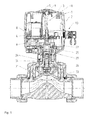
- Fig. 1 shows the inventive device in longitudinal section, the device 1 is already attached to the diaphragm valve 20.
- the inventive device 1 has a housing 2, wherein the housing 2 is preferably made of a lower part 4 and an upper part 3 consists.
- an electric motor 7 which drives the gear assembly 6 and this in turn drives the diaphragm valve 20 or its spindle nut 26, which is responsible for the stroke of the diaphragm 21.
- the device 1 has a position indicator 11.
- the position indicator 11 is also driven by the gear assembly 6.
- the revolutions required to open and close the diaphragm valve 20 are translated by means of gear assembly 6 and, if necessary, other gear stages such that during max. one revolution of the position indicator 11, each opening degree of the diaphragm valve 20 can be displayed.
- the device 1 preferably has an initiator 30, wherein the initiator 30 is preferably arranged on the position indicator 11, by means of which the exact opening degree of the diaphragm valve 20 can be detected.
- a preferred initiator 30 is in Fig. 3 a rotary encoder which preferably works magnetically. Other initiators or rotary tanners which are known from the prior art can be used.
- a base plate 8 with the electrical components mounted thereon is arranged in the device 1. The energy supply takes place via a connection 10.
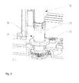
- Fig. 2 shows, inter alia, an exemplary structure of a gear assembly 6 in the inventive device 1.
- the electric motor 7 is preferably arranged on the upper base plate 14 of the gear assembly 6.
- a gear (not shown) is arranged, which meshes with a gear 17 of the gear assembly 6.
- the gear assembly 6 has so many gears 17 and gear stages that the required torque for actuating the diaphragm valve 20 and the spindle nut 26 can be achieved. Why also the structure of such a transmission assembly 6 with the gears 17 disposed therein is to be interpreted individually, depending on the driving electric motor 6 and the available space. Due to the three-dimensional sectional view in Fig. 2 is the position indicator 11 arranged in the device 1, which is driven via the gear assembly 6, clearly visible.
- the gear assembly 6 has different gears 17, which are arranged in several gear stages, wherein the gear 22 is positively connected by means of an adapter 25 with the spindle nut 26.
- the driven gear 22 is thus located in the same axis as the spindle nut 26 and preferably also the position indicator 11.
- a further gear 19 is arranged coaxially thereto and are firmly connected , wherein the gear 19 thus has the same speed and preferably a much smaller diameter, since the aim is to show the multiple revolutions needed for the opening and closing of the valve 20 during a maximum of one revolution of the position indicator 11.
- the gear 19 which has the rotational speed of the spindle nut 26, with the connected to the spindle nut 26 gear 22 and the spindle nut 26 itself, arranged coaxially.
- the gear 19 is disposed above the upper base plate 14 and drives a further gear stage 16, wherein the further gear stage 16 for speed reduction and thus the position indicator 11 is used.
- the further gear stage 16 has a gear 13, which is driven by the gear 19, which has a larger diameter than the gear 19, whereby already here the speed is reduced.
- the arranged on the same gear stage 16 gear 27 which is coaxially and fixedly connected to the gear 13, therefore assumes its speed and drives the gear 23, which is fixedly connected to the position indicator shaft 12.
- the position indicator shaft 12 of the position indicator 11 is rotatably mounted on the axis 28 with the gear 23 fixedly arranged thereon.
- the display button 9 is arranged, which rotates correspondingly with the position indicator shaft 12.
- an initiator 30, can be seen in Fig. 3 , This detects the exact position or the opening degree of the diaphragm valve 20 and transmits the detected position to a controller which communicates with the motor 7.
- the in Fig. 3 The illustrated magnetic rotary encoder is a possible initiator 30 which can be used for this purpose.
- a magnet holder 33 is arranged, on which a magnetic ring 32 of the initiator 30 or in this embodiment of a magnetic rotary encoder is arranged.
- a magnetic ring 32 of the initiator 30 or in this embodiment of a magnetic rotary encoder is arranged.
- To determine the position of the position sensor 31 is used with the help of the magnetic ring 32 detects the position of the membrane.
- Such initiators are well known in the art.
- the gear assembly 6 has an upper and lower base plate 14, 15, which are spaced from each other by means of spacer bolts 18 and between the gears 17, 22 are arranged and supported for driving the spindle nut 26.
- other gear stages for translation to the position indicator can also be arranged between the base plates.
- the clear area 5 in the housing 2 allows the view of the display button 9 and thus the possibility that the complete position indicator 11 is arranged in the sealed housing 2.
- the device 1 In order to fix the device 1 on a diaphragm valve 20, it has an intermediate element 24 preferably made of plastic, which in Fig. 1 is apparent.
- the intermediate element 24 serves as a kind of transition piece and makes it possible to mount the device 1 with the receptacle 29 arranged thereon on the diaphragm valve 20.
- the intermediate element 24 is positively connected to the device 1 according to the invention and the diaphragm valve 20 in order to transmit the torques.
- the fastening means 34 for fastening the intermediate element 24 on the diaphragm valve 20 are not accessible in the assembled state and thereby protected against external influences.
- an adapter 25 is positively connected to the spindle nut 26 and the gear 22.
Abstract
Vorrichtung (1) zur Betätigung eines Membranventils beinhaltend ein Gehäuse (2), wobei das Gehäuse vorzugsweise aus einem Ober- (3) und Unterteil gebildet ist, einen Elektromotor (7), eine Basisplatine zur Befestigung von elektrischen Bauteilen, eine Getriebebaugruppe (6) zur Betätigung des Membranventils bzw. der Spindelmutter des Membranventils und eine Stellungsanzeige (11) zur Anzeige des Öffnungsgrades des Membranventils, wobei die Stellungsanzeige über die Getriebebaugruppe angetrieben ist.Device (1) for actuating a diaphragm valve comprising a housing (2), wherein the housing is preferably formed from an upper (3) and lower part, an electric motor (7), a base board for fixing electrical components, a gear assembly (6) for actuating the diaphragm valve or the spindle nut of the diaphragm valve and a position indicator (11) for indicating the opening degree of the diaphragm valve, wherein the position indicator is driven via the gear assembly.
Description
Die Erfindung betrifft eine Vorrichtung zur Betätigung eines Membranventils beinhaltend ein Gehäuse, wobei das Gehäuse vorzugsweise aus einem Ober- und Unterteil gebildet ist, einen Elektromotor, eine Basisplatine zur Befestigung von elektrischen Bauteilen, eine Getriebebaugruppe zur Betätigung des Membranventils bzw. der Spindelmutter des Membranventils und eine Stellungsanzeige zur Anzeige des Öffnungsgrades des Membranventils.The invention relates to a device for actuating a diaphragm valve comprising a housing, wherein the housing is preferably formed of an upper and lower part, an electric motor, a base board for mounting electrical components, a transmission assembly for actuating the diaphragm valve or the spindle nut of the diaphragm valve and a position indicator to indicate the opening degree of the diaphragm valve.
Membranventile werden in Rohrleitungssystemen als Absperrorgan oder zur Regelung des Durchflusses von Fluiden eingesetzt. Membranventile zeichnen sich dadurch aus, dass sie gegen verschmutzte Medien eher unempfindlich sind. Unter anderem kommen Membranventile in der chemischen Prozessindustrie, Wasseraufbereitung, in Kraftwerken, für Kühl-oder Regelapplikationen, usw. zur Anwendung. Membranventile können manuell, pneumatisch oder elektrisch gesteuert bzw. angetrieben werden. Bei automatisch gesteuerten Anlagen werden elektrisch angetriebene Membranventile bevorzugt. Ein solcher Antrieb hat den Vorteil, dass alle im System damit ausgerüsteten Membranventile zentral von einem Ort aus gesteuert bzw. geregelt werden können.Diaphragm valves are used in piping systems as shut-off valves or to control the flow of fluids. Diaphragm valves are characterized by the fact that they are rather insensitive to soiled media. Among other things, diaphragm valves are used in the chemical process industry, water treatment, in power plants, for cooling or control applications, etc. Diaphragm valves can be controlled or driven manually, pneumatically or electrically. In automatically controlled systems electrically driven diaphragm valves are preferred. Such a drive has the advantage that all diaphragm valves equipped with it in the system can be centrally controlled or regulated from one location.
Die
Nachteilig hierbei ist der herausragende Griff, welcher als Schauglas dient und durch seine exponierte Position schnell beschädigt werden kann sowie auch mehr Platz für den Einbau benötigt wird.The disadvantage here is the outstanding handle, which serves as a sight glass and can be damaged by its exposed position quickly and also more space is required for installation.
Es ist Aufgabe der Erfindung eine Vorrichtung zur Betätigung eines Membranventils vorzuschlagen bei der der Öffnungsgrad des Membranventils gut erkennbar ist und eine eindeutige Stellung der Armatur bei mehreren Umdrehungen angibt. Die Vorrichtung soll auf jedes manuelle Membranventil adaptierbar bzw. mit einem Handantrieb austauschbar sein. Durch die Austauschbarkeit soll es möglich sein ein manuell betriebenes Membranventil möglichst einfach ohne viel Aufwand und viele Kosten in ein automatisch betriebenes Membranventil umzurüsten, welches aber dennoch eine visuelle Kontrolle des Öffnungsgrads des Membranventils zulässt.It is an object of the invention to provide a device for actuating a diaphragm valve in which the degree of opening of the diaphragm valve is clearly visible and indicates a unique position of the valve at several revolutions. The device should be adaptable to each manual diaphragm valve or be interchangeable with a manual drive. Due to the interchangeability it should be possible manually operated diaphragm valve as simple as possible without much effort and many costs to convert into an automatically operated diaphragm valve, but still allows a visual control of the opening degree of the diaphragm valve.
Die Aufgabe wird dadurch gelöst, dass die Stellungsanzeige über die Getriebebaugruppe angetrieben ist.The object is achieved in that the position indicator is driven by the gear assembly.
Die Vorrichtung zur Betätigung des Membranventils beinhaltet ein Gehäuse, wobei das Gehäuse vorzugsweise aus einem Ober- und Unterteil gebildet ist. Selbstverständlich kann das Gehäuse auch aus noch mehreren Teilen gebildet werden. Das Gehäuse wird vorzugsweise im Spritzgiessverfahren hergestellt. Zudem beinhaltet die Vorrichtung einen Elektromotor, welcher über die Getriebebaugruppe das Membranventil bzw. der Spindelmutter betätigt, wodurch sich die Membrane hebt und senkt. Des Weiteren weist die Vorrichtung eine Basisplatine auf, auf der die elektrischen Bauteile angeordnet sind.The device for actuating the diaphragm valve includes a housing, wherein the housing is preferably formed from an upper and lower part. Of course, the housing can be formed from even more parts. The housing is preferably produced by injection molding. In addition, the device includes an electric motor which actuates the membrane valve or the spindle nut via the gear assembly, whereby the membrane raises and lowers. Furthermore, the device has a base board on which the electrical components are arranged.
Zur visuellen Überprüfung der Position der Membrane bzw. des Öffnungsgrads des Membranventils beinhaltet die Vorrichtung eine Stellungsanzeige, wobei die Stellungsanzeige ebenfalls über die Getriebebaugruppe angetrieben ist.For visual inspection of the position of the diaphragm or the opening degree of the diaphragm valve, the device includes a position indicator, wherein the position indicator is also driven by the gear assembly.
Damit der Öffnungsgrad des Membranventils bzw. die Position der Membrane eindeutig erkannt wird, weist die Vorrichtung einen Initiator auf. Dieser gibt den genauen Öffnungsgrad des Membranventils wieder. Zudem kann dadurch die Steuerung bei einem Stromausfall die genaue Position bzw. Stellung der Membrane erkennen bzw. bekommt durch den Initiator ein eindeutiges Signal bezüglich der Position.So that the opening degree of the diaphragm valve or the position of the diaphragm is clearly recognized, the device has an initiator. This indicates the exact opening degree of the diaphragm valve. In addition, the controller can recognize the exact position or position of the membrane in the event of a power failure or receives a clear signal with respect to the position by the initiator.
Vorzugsweise ist der Initiator an der Stellungsanzeige angeordnet. Als bevorzugter Initiator hat sich ein Drehgeber erwiesen, wobei auch andere Initiatoren die die genaue Position der Membrane bzw. der Stellungsanzeige erfassen können denkbar und einsetzbar sind.Preferably, the initiator is arranged on the position indicator. As a preferred initiator, a rotary encoder has been found, with other initiators can detect the exact position of the membrane or the position indicator are conceivable and usable.
Die Getriebebaugruppe weist vorzugsweise eine obere und untere Grundplatte auf, zwischen denen die Zahnräder zur gewünschten Kraftübertragung und Drehzahlübersetzungen angeordnet sind. Vorzugsweise sind in der Getriebebaugruppe ausschliesslich Stirnräder eingesetzt, wobei die Zahnräder aus unterschiedlichen Materialien wie auch aus einheitlichen Materialien gebildet sein können.The gear assembly preferably has upper and lower base plates, between which the gears are arranged for the desired power transmission and speed ratios. Preferably, in the Gear unit exclusively used spur gears, wherein the gears may be formed of different materials as well as of uniform materials.
Die Grundplatten der Getriebebaugruppen sind mittels Distanzbolzen voneinander beabstandet damit die meisten der Zahnräder dazwischen angeordnet werden können. Alternative Bauweisen einer solchen Getriebebaugruppe sind selbstverständlich möglich. Wie zuvor bereits erwähnt ist auch die Stellungsanzeige über die Getriebebaugruppe angetrieben.The base plates of the gear assemblies are spaced apart by spacer bolts so that most of the gears can be interposed therebetween. Alternative constructions of such a transmission assembly are of course possible. As already mentioned above, the position indicator is also driven via the gear unit assembly.
Vorzugsweise ist die Vorrichtung elektrisch betrieben bzw. mittels elektischem Strom.Preferably, the device is electrically operated or by means of electrical current.
Die Stellungsanzeige zeigt den Öffnungsgrad des Membranventils durch eine rotative Bewegung an. Die Stellungsanzeige entspricht einer Drehanzeige in dem auf dem Anzeigebutton der Stellungsanzeige bspw. ein Anzeigesymbol dargestellt ist, das sich bei Betätigung in die entsprechenden Position ausrichtet bzw. dreht, die bspw. durch eine Skala um den Anzeigebutton am Gehäuse gebildet ist. Diese Drehbewegung wird über das Getriebe initiiert und verläuft entsprechend der Betätigung der Spindelmutter, nur mit einer anderen bzw. zusätzlichen Übersetzung.The position indicator indicates the opening degree of the diaphragm valve by a rotary movement. The position indicator corresponds to a rotary display in which on the Anzeigebedutton the position indicator, for example, a display icon is shown, which aligns when actuated in the corresponding position, which is formed, for example. By a scale around the display button on the housing. This rotational movement is initiated via the gear and runs according to the operation of the spindle nut, only with a different or additional translation.
Da vorzugsweise der Initiator an der Stellungsanzeige angeordnet ist, dreht sich dieser entsprechend mit und gibt die eindeutige Position bzw. Öffnungsgrad des Membranventils wieder.Since the initiator is preferably arranged on the position indicator, it rotates accordingly and reproduces the unambiguous position or opening degree of the diaphragm valve.
Die Stellungsanzeige beinhaltet als vorteilhafte Ausgestaltung eine Stellungsanzeigewelle und einen Anzeigebutton. Die Stellungsanzeigewelle verläuft vertikal in der Vorrichtung, wobei der Anzeigebutton am oberen Ende der Stellungsanzeigewelle angeordnet ist.The position indicator includes, as an advantageous embodiment, a position indicator shaft and a display button. The position indicator shaft extends vertically in the device with the display button located at the top of the position indicator shaft.
Die Stellungsanzeige bzw. die Stellungsanzeigewelle verläuft koaxial zur Spindelmutter des Membranventils. Vorzugsweise verläuft die Stellungsanzeige koaxial mit dem direkt mit der Spindelmutter formschlüssig verbundenen Zahnrad der Getriebebaugruppe.The position indicator or the position indicator shaft runs coaxially to the spindle nut of the diaphragm valve. Preferably, the position indicator is coaxial with the directly connected to the spindle nut geared gear of the transmission assembly.
Als bevorzugte Ausgestaltung hat sich gezeigt, dass das Gehäuse einen Klarsichtbereich aufweist, der oberhalb des Anzeigebuttons angeordnet ist und dadurch die Sicht auf den Anzeigebutton und somit auf das Anzeigesymbol, welches die Stellung des Membranventils anzeigt, ermöglicht. Durch diese vorteilhafte Ausführungsform kann die komplette Stellungsanzeige im Gehäuse der Vorrichtung angeordnet werden, wodurch zusätzliche Dichtstellen vermieden werden können und eine Verschmutzung im Inneren der Vorrichtung auf ein Minimum reduziert werden kann. Selbstverständlich bestehen aber auch andere Möglichkeiten der Anordnung eines Klarsichtbereichs am Gehäuse.As a preferred embodiment, it has been found that the housing has a transparent area, which is arranged above the display button and thereby allows the view of the display button and thus on the display icon, which indicates the position of the diaphragm valve. By this advantageous embodiment, the complete position indicator can be arranged in the housing of the device, whereby additional sealing points can be avoided and contamination inside the device can be reduced to a minimum. Of course, there are other possibilities of arranging a clear area on the housing.
Damit eine eindeutige Anzeige des Öffnungsgrads des Membranventils erfolgt, weist das Getriebe eine derartige Übersetzung auf, dass die mehreren Umdrehungen der Spindelmutter, die zum kompletten Öffnen und/oder Schliessen des Membranventils benötigt sind, in maximal eine Umdrehung der Stellungsanzeige, zur Anzeige des Öffnungsgrads des Membranventils, übersetzt sind. Mittels des Initiators der vorzugsweise an der Stellungsanzeige angeordnet ist, kann eine Steuerung für die erfindungsgemässe Vorrichtung die Stellung des Membranventils erkennen und auch nach Stromausfall bleibt die Anzeige und Stellungsrückmeldung eindeutig.In order for a clear indication of the opening degree of the diaphragm valve, the transmission has such a translation that the multiple revolutions of the spindle nut, which are required to completely open and / or close the diaphragm valve, in a maximum of one revolution of the position indicator, to display the opening degree of Diaphragm valve, are translated. By means of the initiator which is preferably arranged on the position indicator, a controller for the device according to the invention can detect the position of the diaphragm valve and even after a power failure, the display and position feedback remains unambiguous.
Vorzugsweise wird eine solche Übersetzung dadurch gebildet, indem mindestens eine weitere bzw. eine zusätzliche Getriebestufe in der Getriebebaugruppe angeordnet ist bzw. an die Getriebebaugruppe anschliesst, die dem Antrieb der Stellungsanzeige dient. Das heisst, dass bspw. das Zahnrad, welches mit der Spindelmutter formschlüssig verbunden ist mit einem weiteren Zahnrad starr verbunden ist, welches koaxial dazu angeordnet ist und demzufolge mit derselben Drehzahl läuft, jedoch einen geringeren Durchmesser hat und dieses wiederum mit einem weiteren Zahnrad kämmt um die Drehzahl zu reduzieren, welches dann über ein abtreibendes, koaxial dazu angeordnetes Zahnrad, das an der Stellungsanzeige angeordnete Zahnrad anzutreiben.Preferably, such a translation is formed by at least one further or an additional gear stage is arranged in the transmission assembly and connects to the transmission assembly, which serves to drive the position indicator. This means that, for example, the gear, which is positively connected to the spindle nut is rigidly connected to another gear, which is arranged coaxially thereto and thus runs at the same speed, but has a smaller diameter and this in turn with another gear meshes To reduce the speed, which then via an abreibendes coaxially arranged gear to drive the arranged on the position indicator gear.
Die weiteren bzw. zusätzlichen Getriebestufen können in der Getriebebaugruppe bzw. zwischen der oberen- und unteren Grundplatte angeordnet sein, wie auch ausserhalb. Eine vorteilhafte Ausgestaltung hat sich gezeigt, wenn zusätzliche Getriebestufen auf der oberen Grundplatte der Getriebebaugruppe angeordnet sind. Eine solche Ausgestaltung macht die Vorrichtung variabel einsetzbar und die Übersetzung kann durch Austausch der Zahnräder einfach geändert werden.The additional or additional gear stages can be arranged in the gear assembly or between the upper and lower base plate, as well as outside. An advantageous embodiment has been found when additional gear stages are arranged on the upper base plate of the gear assembly. Such a configuration makes the device variable and the translation can be easily changed by replacing the gears.
Durch eine Übersetzung bzw. die Verbindung der Spindelmutter des Membranventils mit der Getriebebaugruppe wird die Hubbewegung der Membrane mittels der Spindelmutter in eine rotative Bewegung umgeformt und die Mehrfachumdrehungen der Spindelmutter für den benötigten Hub der Membrane in maximal eine Umdrehung auf die Stellungsanzeige übersetzt, wodurch der Öffnungsgrad des Membranventils angezeigt wird.By a translation or the connection of the spindle nut of the diaphragm valve with the gear assembly, the lifting movement of the diaphragm is converted by means of the spindle nut in a rotary motion and the multiple rotations of the spindle nut for the required stroke of the diaphragm translated into a maximum of one revolution on the position indicator, whereby the degree of opening of the diaphragm valve is displayed.
Als Vorteilhaft hat sich gezeigt, dass die Vorrichtung ein Zwischenelement aufweist, das zur Befestigung der Vorrichtung am Membranventil dient. Dieses Zwischenelement ist derart ausgebildet, dass die Vorrichtung auf bereits bestehende, mit Handantrieb ausgestattete Membranventile adaptiert werden kann bzw. die Vorrichtung anstelle des Handantriebs angebracht werden kann.As an advantage, it has been shown that the device has an intermediate element which serves for fastening the device to the diaphragm valve. This intermediate element is designed in such a way that the device can be adapted to existing, manually-operated diaphragm valves or the device can be mounted instead of the manual drive.
Vorzugsweise weist die Vorrichtung einen Adapter auf, der die Getriebebaugruppe mit dem Membranventil bzw. der Spindelmutter koppelt.Preferably, the device has an adapter which couples the gear assembly with the diaphragm valve or the spindle nut.
Ein Ausführungsbeispiel der Erfindung wird anhand der Figuren beschrieben, wobei sich die Erfindung nicht nur auf das Ausführungsbeispiel beschränkt. Es zeigen:
- Fig. 1
- einen Längsschnitt durch eine erfindungsgemässe Vorrichtung, die bereits auf einem Membranventil befestigt ist,
- Fig. 2
- eine dreidimensionale Schnittansicht einer erfindungsgemässen Vorrichtung und
- Fig. 3
- einen dreidimensionalen Ausschnitt der erfindungsgemässen Vorrichtung im Bereich des Initiators.
- Fig. 1
- a longitudinal section through an inventive device which is already mounted on a diaphragm valve,
- Fig. 2
- a three-dimensional sectional view of an inventive device and
- Fig. 3
- a three-dimensional section of the inventive device in the region of the initiator.
Die Getriebebaugruppe 6 weist unterschiedliche Zahnräder 17 auf, die in mehreren Getriebestufen angeordnet sind, wobei das Zahnrad 22 mittels eines Adapters 25 formschlüssig mit der Spindelmutter 26 verbunden ist. Das angetriebene Zahnrad 22 befindet sich somit in derselben Achse wie die Spindelmutter 26 und vorzugsweise auch der Stellungsanzeige 11. Um den Öffnungsgrad des Membranventils 20 mit der Stellungsanzeige 11 aufzuzeigen, ist mit dem Zahnrad 22 ein weiteres Zahnrad 19 koaxial dazu angeordnet und sind fest miteinander verbunden, wobei das Zahnrad 19 somit dieselbe Drehzahl und vorzugsweise einen wesentlich kleineren Durchmesser aufweist, da das Ziel darin besteht, die mehreren Umdrehungen, die für das Öffnen und Schliessen des Ventils 20 benötigt werden, während maximal einer einzigen Umdrehung der Stellungsanzeige 11 aufzuzeigen. Somit ist das Zahnrad 19, welches die Drehzahl der Spindelmutter 26 aufweist, mit dem mit der Spindelmutter 26 verbundenen Zahnrad 22 und der Spindelmutter 26 selbst, koaxial angeordnet. Vorzugsweise ist das Zahnrad 19 oberhalb der oberen Grundplatte 14 angeordnet und treibt eine weitere Getriebestufe 16 an, wobei die weitere Getriebestufe 16 zur Drehzahlreduzierung und somit der Stellungsanzeige 11 dient. Somit weist die weitere Getriebestufe16 ein Zahnrad 13 auf, welches durch das Zahnrad 19 angetrieben wird, welches einen grösseren Durchmesser aufweist als das Zahnrad 19, wodurch bereits hier die Drehzahl reduziert wird. Das auf derselben Getriebestufe 16 angeordnete Zahnrad 27, das koaxial und fest mit dem Zahnrad 13 verbunden ist, übernimmt demzufolge dessen Drehzahl und treibt das Zahnrad 23 an, welches fest mit der Stellungsanzeigewelle 12 verbunden ist. Da das Zahnrad 23 vorzugsweise einen grösseren Durchmesser als das antreibende Zahnrad 27 aufweist, wird hier wiederum die Drehzahl verringert. Die Stellungsanzeigewelle 12 der Stellungsanzeige 11 ist mit dem fest daran angeordneten Zahnrad 23 auf der Achse 28 drehbar gelagert. Am oberen Ende der Stellungsanzeige 11 ist der Anzeigebutton 9 angeordnet, der sich entsprechend mit der Stellungsanzeigewelle 12 mitdreht. Vorzugsweise befindet sich an der Stellungsanzeige 11 ein Initiator 30, ersichtlich in
Als bevorzugter Aufbau der Getriebebaugruppe 6 weist sie eine obere und untere Grundplatte 14, 15 auf, die mittels Distanzbolzen 18 voneinander beanstandet sind und dazwischen die Zahnräder 17, 22 zum Antreiben des Spindelmutter 26 angeordnet und gelagert sind. Wobei auch wie zuvor erwähnt, weitere Getriebestufen zur Übersetzung auf die Stellungsanzeige auch zwischen den Grundplatten angeordnet sein können.As a preferred construction of the
Der Klarsichtbereich 5 im Gehäuse 2 ermöglicht den Blick auf den Anzeigebutton 9 und somit die Möglichkeit, dass die komplette Stellungsanzeige 11 im abgedichteten Gehäuse 2 angeordnet ist.The
Um die Vorrichtung 1 auf einem Membranventil 20 zu befestigen, weist sie ein Zwischenelement 24 vorzugsweise aus Kunststoff auf, was in
Um die Kraftübertragung der Vorrichtung 1 auf die Spindelmutter 26 zu ermöglichen, ist ein Adapter 25 mit der Spindelmutter 26 und dem Zahnrad 22 formschlüssig verbunden.In order to enable the power transmission of the device 1 to the
- 11
- Vorrichtungcontraption
- 22
- Gehäusecasing
- 33
- Oberteil GehäuseUpper part housing
- 44
- Unterteil GehäuseLower part housing
- 55
- KlarsichtbereichTransparent area
- 66
- Getriebebaugruppetransmission assembly
- 77
- Elektromotorelectric motor
- 88th
- BasisplatineDevelopment board
- 99
- Anzeigebuttondisplay button
- 1010
- Anschluss zum Anschliessen der EnergieversorgungConnection for connecting the power supply
- 1111
- Stellungsanzeigeposition indicator
- 1212
- StellungsanzeigewellePosition indicator shaft
- 1313
- Angetriebenes ZahnradPowered gear
- 1414
- Obere GrundplatteUpper base plate
- 1515
- Untere GrundplatteLower base plate
- 1616
- Weitere GetriebestufeFurther gear stage
- 1717
- Zahnrädergears
- 1818
- DistanzbolzenDistance bolts
- 1919
- Zahnrad, fest mit Zahnrad 22 verbundenGear, fixed to gear 22 connected
- 2020
- Membranventildiaphragm valve
- 2121
- Membranemembrane
- 2222
- Zahnrad formschlüssig über Adapter mit Spindelmutter verbundenGear positively connected via adapter with spindle nut
- 2323
- Zahnrad an StellungsanzeigewelleGear on position indicator shaft
- 2424
- Zwischenelementintermediate element
- 2525
- Adapteradapter
- 2626
- Spindelmutter MembranventilSpindle nut diaphragm valve
- 2727
-
Abtreibendes Zahnrad / antreibendes Zahnrad in Bezug auf Zahnrad 23Abortion gear / driving gear with respect to
gear 23 - 2828
- Feste AchseFixed axis
- 2929
- Aufnahmeadmission
- 3030
- Initiatorinitiator
- 3131
- Positionsabnehmerposition pickup
- 3232
- Magnetringmagnetic ring
- 3333
- Magnethaltermagnetic holder
- 3434
- Befestigungsmittelfastener
Claims (15)
Priority Applications (5)
| Application Number | Priority Date | Filing Date | Title |
|---|---|---|---|
| EP15170181.0A EP3073163A1 (en) | 2015-03-11 | 2015-06-02 | Drive for a membrane valve |
| US15/066,686 US9989163B2 (en) | 2015-03-11 | 2016-03-10 | Diaphragm valve drive |
| KR1020160029015A KR102378912B1 (en) | 2015-03-11 | 2016-03-10 | Diaphragm valve drive |
| JP2016048164A JP6676420B2 (en) | 2015-03-11 | 2016-03-11 | Device for operating a diaphragm valve |
| CN201610138356.0A CN105972305A (en) | 2015-03-11 | 2016-03-11 | Driving device of membrane valve |
Applications Claiming Priority (2)
| Application Number | Priority Date | Filing Date | Title |
|---|---|---|---|
| EP15158553.6A EP3067602B1 (en) | 2015-03-11 | 2015-03-11 | Drive with light guide |
| EP15170181.0A EP3073163A1 (en) | 2015-03-11 | 2015-06-02 | Drive for a membrane valve |
Publications (1)
| Publication Number | Publication Date |
|---|---|
| EP3073163A1 true EP3073163A1 (en) | 2016-09-28 |
Family
ID=52736837
Family Applications (2)
| Application Number | Title | Priority Date | Filing Date |
|---|---|---|---|
| EP15158553.6A Active EP3067602B1 (en) | 2015-03-11 | 2015-03-11 | Drive with light guide |
| EP15170181.0A Withdrawn EP3073163A1 (en) | 2015-03-11 | 2015-06-02 | Drive for a membrane valve |
Family Applications Before (1)
| Application Number | Title | Priority Date | Filing Date |
|---|---|---|---|
| EP15158553.6A Active EP3067602B1 (en) | 2015-03-11 | 2015-03-11 | Drive with light guide |
Country Status (6)
| Country | Link |
|---|---|
| US (2) | US9945491B2 (en) |
| EP (2) | EP3067602B1 (en) |
| JP (2) | JP6682306B2 (en) |
| KR (2) | KR102381807B1 (en) |
| CN (2) | CN105972305A (en) |
| ES (1) | ES2741313T3 (en) |
Cited By (1)
| Publication number | Priority date | Publication date | Assignee | Title |
|---|---|---|---|---|
| DE102019124149A1 (en) * | 2019-09-09 | 2021-03-11 | Auma Riester Gmbh & Co. Kg | Actuator and method for controlling a brake of an actuator |
Families Citing this family (6)
| Publication number | Priority date | Publication date | Assignee | Title |
|---|---|---|---|---|
| EP3514428A1 (en) | 2018-01-18 | 2019-07-24 | Georg Fischer Rohrleitungssysteme AG | Hand lever |
| JP7107694B2 (en) * | 2018-02-20 | 2022-07-27 | 日本ギア工業株式会社 | Opening indicator for electric valve drive |
| JP7133945B2 (en) | 2018-03-02 | 2022-09-09 | 株式会社堀場エステック | Fluid control valve and fluid control device |
| EP3722642B1 (en) | 2019-04-10 | 2022-02-23 | Georg Fischer Rohrleitungssysteme AG | Butterfly valve |
| DE102021120287A1 (en) | 2021-08-04 | 2023-02-09 | Gemü Gebr. Müller Apparatebau Gmbh & Co. Kommanditgesellschaft | Clamping assembly for a process valve |
| USD1015487S1 (en) * | 2022-11-04 | 2024-02-20 | Georg Fischer Rohrleitungssysteme Ag | Electric actuator for valves |
Citations (3)
| Publication number | Priority date | Publication date | Assignee | Title |
|---|---|---|---|---|
| DE2417057A1 (en) * | 1974-04-03 | 1975-10-23 | Sulzer Ag | ACTUATOR, IN PARTICULAR FOR VALVES |
| DE3520502C2 (en) | 1985-06-07 | 1994-05-05 | Fritz Mueller | Driving device for valves |
| DE10322832B4 (en) * | 2003-05-19 | 2006-07-13 | Georg Fischer Rohrleitungssysteme Ag | Device for manual override of valves |
Family Cites Families (34)
| Publication number | Priority date | Publication date | Assignee | Title |
|---|---|---|---|---|
| BE755327A (en) * | 1970-02-27 | 1971-02-01 | Pratt Co Henry | Valve position indicator. |
| US3768775A (en) * | 1972-02-24 | 1973-10-30 | Ver Vaecke C | Portable valve actuator |
| US4090589A (en) * | 1975-10-23 | 1978-05-23 | John Herman Fitzwater | Fail safe valve actuator |
| JPH0227740Y2 (en) * | 1985-04-19 | 1990-07-26 | ||
| JPH0535260Y2 (en) * | 1987-03-17 | 1993-09-07 | ||
| US4940011A (en) * | 1989-05-19 | 1990-07-10 | Limitorque Corporation | Valve actuator two rotor three position indicator |
| JPH05126272A (en) * | 1991-11-06 | 1993-05-21 | Sekisui Chem Co Ltd | Electrically-driven actuator for valve |
| JPH0577673U (en) * | 1992-03-25 | 1993-10-22 | 積水化学工業株式会社 | Electric actuator for valves |
| US5277223A (en) * | 1992-10-16 | 1994-01-11 | Glockner Gary G | Valve position transmitter |
| JPH11223273A (en) * | 1998-02-05 | 1999-08-17 | Shimadzu Corp | Valve opening display |
| US6609533B2 (en) * | 2001-03-08 | 2003-08-26 | World Wide Oilfield Machine, Inc. | Valve actuator and method |
| DE10115472A1 (en) * | 2001-03-29 | 2002-10-10 | Duerr Systems Gmbh | Valve unit for use in electrostatic painting apparatus has an optoelectronic sensor device with light wave conductors and an optoelectronic sensor to sense an indexing position and to generate a corresponding sensing signal. |
| US20040058437A1 (en) * | 2001-04-10 | 2004-03-25 | Rodgers Seth T. | Materials and reactor systems having humidity and gas control |
| US6498551B1 (en) * | 2001-08-20 | 2002-12-24 | Xytrans, Inc. | Millimeter wave module (MMW) for microwave monolithic integrated circuit (MMIC) |
| JP4195830B2 (en) * | 2003-05-12 | 2008-12-17 | 岩井機械工業株式会社 | Valve head |
| JP2005003027A (en) * | 2003-06-10 | 2005-01-06 | Tomoe Tech Res Co | Opening degree detecting device for rotary valve |
| JP4512347B2 (en) * | 2003-11-11 | 2010-07-28 | 三菱レイヨン株式会社 | Switching valve and water purifier |
| JP2005273834A (en) * | 2004-03-25 | 2005-10-06 | Tomoe Tech Res Co | Positioner for valve |
| JP2005273857A (en) * | 2004-03-26 | 2005-10-06 | Tomoe Tech Res Co | Positioner for valve |
| JP4652012B2 (en) * | 2004-10-14 | 2011-03-16 | 株式会社キッツ | Electric actuator |
| WO2008138374A1 (en) * | 2007-05-12 | 2008-11-20 | Festo Ag & Co. Kg | Fluid-technical assembly having an optical waveguide |
| DE102008064406B4 (en) * | 2008-11-03 | 2016-03-24 | Ps Automation Gmbh | Display device for an actuator and actuator for a valve |
| US8231833B2 (en) * | 2009-03-24 | 2012-07-31 | Lockheed Martin Corporation | Direct optical interrogation of agents in micro-fluidic channels utilizing whispering gallery resonator approach |
| EP2236874B2 (en) * | 2009-04-01 | 2015-04-08 | Georg Fischer Rohrleitungssysteme AG | Membrane valve |
| US8550115B2 (en) * | 2009-07-21 | 2013-10-08 | Trumbull Industries, Inc. | Valve position indicator |
| US9347583B2 (en) * | 2009-07-21 | 2016-05-24 | Trumbull Manufacturing, Inc. | Valve position indicator |
| DE102009047481A1 (en) * | 2009-12-04 | 2011-06-09 | Osram Gesellschaft mit beschränkter Haftung | light module |
| US8689826B2 (en) * | 2011-05-25 | 2014-04-08 | Trident Emergency Products, Llc | Valve control hand wheel with position indicator and magnetic couple feature |
| JP5761361B2 (en) * | 2011-10-03 | 2015-08-12 | 富士通株式会社 | Optical semiconductor device, control method thereof, and manufacturing method thereof |
| US20140096850A1 (en) * | 2011-12-15 | 2014-04-10 | Honeywell International Inc. | Visual indicator for a safety shut off valve |
| US8978699B2 (en) * | 2012-09-07 | 2015-03-17 | Cameron International Corporation | Blowout preventer status assembly |
| DE202012010469U1 (en) * | 2012-10-30 | 2012-11-15 | Bürkert Werke GmbH | Device for indicating the position of a valve spindle |
| CN103486323A (en) * | 2013-09-26 | 2014-01-01 | 深圳市福田区青少年科技教育协会 | Water temperature controllable faucet |
| US9447897B2 (en) * | 2014-12-02 | 2016-09-20 | Vir Valvoindustria Ing. Rizzio S.P.A. | Handwheel for hydraulic valve provided with opening level indicator |
-
2015
- 2015-03-11 EP EP15158553.6A patent/EP3067602B1/en active Active
- 2015-03-11 ES ES15158553T patent/ES2741313T3/en active Active
- 2015-06-02 EP EP15170181.0A patent/EP3073163A1/en not_active Withdrawn
-
2016
- 2016-03-10 US US15/066,622 patent/US9945491B2/en active Active
- 2016-03-10 US US15/066,686 patent/US9989163B2/en active Active
- 2016-03-10 KR KR1020160029013A patent/KR102381807B1/en active IP Right Grant
- 2016-03-10 KR KR1020160029015A patent/KR102378912B1/en active IP Right Grant
- 2016-03-11 CN CN201610138356.0A patent/CN105972305A/en active Pending
- 2016-03-11 JP JP2016048162A patent/JP6682306B2/en active Active
- 2016-03-11 CN CN201610138288.8A patent/CN105972286B/en active Active
- 2016-03-11 JP JP2016048164A patent/JP6676420B2/en active Active
Patent Citations (3)
| Publication number | Priority date | Publication date | Assignee | Title |
|---|---|---|---|---|
| DE2417057A1 (en) * | 1974-04-03 | 1975-10-23 | Sulzer Ag | ACTUATOR, IN PARTICULAR FOR VALVES |
| DE3520502C2 (en) | 1985-06-07 | 1994-05-05 | Fritz Mueller | Driving device for valves |
| DE10322832B4 (en) * | 2003-05-19 | 2006-07-13 | Georg Fischer Rohrleitungssysteme Ag | Device for manual override of valves |
Cited By (1)
| Publication number | Priority date | Publication date | Assignee | Title |
|---|---|---|---|---|
| DE102019124149A1 (en) * | 2019-09-09 | 2021-03-11 | Auma Riester Gmbh & Co. Kg | Actuator and method for controlling a brake of an actuator |
Also Published As
| Publication number | Publication date |
|---|---|
| EP3067602B1 (en) | 2019-05-08 |
| KR102381807B1 (en) | 2022-03-31 |
| US20160265684A1 (en) | 2016-09-15 |
| CN105972305A (en) | 2016-09-28 |
| KR102378912B1 (en) | 2022-03-24 |
| JP2016169866A (en) | 2016-09-23 |
| JP6682306B2 (en) | 2020-04-15 |
| CN105972286A (en) | 2016-09-28 |
| CN105972286B (en) | 2020-03-13 |
| US9989163B2 (en) | 2018-06-05 |
| US20160265676A1 (en) | 2016-09-15 |
| JP2016169867A (en) | 2016-09-23 |
| ES2741313T3 (en) | 2020-02-10 |
| EP3067602A1 (en) | 2016-09-14 |
| KR20160110229A (en) | 2016-09-21 |
| JP6676420B2 (en) | 2020-04-08 |
| US9945491B2 (en) | 2018-04-17 |
| KR20160110228A (en) | 2016-09-21 |
Similar Documents
| Publication | Publication Date | Title |
|---|---|---|
| EP3073163A1 (en) | Drive for a membrane valve | |
| DE112014004899T5 (en) | Method and device for controlling torque | |
| EP1754566A1 (en) | Turntable with stepping drive | |
| EP0699508B1 (en) | Hydraulic impact screwdriver especially for tightening threaded connection | |
| EP3597369A1 (en) | Method for documented tightening or retightening a screw connection | |
| DE112016005625T5 (en) | Device for injection molding plastic materials | |
| EP2633142B1 (en) | Door drive and control method therefor | |
| DE102014202013B4 (en) | X-ray device | |
| DE102015112685B3 (en) | Drive for moving a grand piano | |
| DE102011013926A1 (en) | Method for rotating a rotatable part | |
| DE19636418A1 (en) | Pneumatic actuator with regulator function | |
| DE2841212A1 (en) | FORCE PLIERS | |
| EP1925772B1 (en) | Sensor unit | |
| DE102009014230A1 (en) | System for simultaneous tightening of multiple fittings in one operation | |
| DE102011112152B4 (en) | Installation for mounting vehicle wheels | |
| EP0359140A2 (en) | Adhesion pull-tester | |
| DE3345528A1 (en) | Method and device for controlling motor-operated high-pressure valves | |
| DE4210201A1 (en) | Compressed air screwdriver tool - has drive motor arranged in housing and connected to compressed air source across air line connected to handle for driving shaft with screwing tool bit and measurement value pick-up at driven shaft | |
| EP3477121B1 (en) | Pressure limiting unit for a pressure booster and a pressure booster for driving of hydraulics tools | |
| EP2937183B1 (en) | Method for actuating a device for screwing components, and device for carrying out the method | |
| DE102006026121A1 (en) | Entry device for use in e.g. supermarket, has back movable door unit conveyed into pre-programmable opening angle position such that control device has recognition device for recognition of momentary actual opening angle positions | |
| DE102015202222A1 (en) | valve drive | |
| DE102012222074A1 (en) | METHOD AND DEVICE FOR INDICATING THE POSITION OF HYDRAULICALLY ACTUATED VALVES | |
| DE102015213760A1 (en) | Tool with a universal, measuring output element and output element | |
| DE102015221027A1 (en) | Method for monitoring mounting positions of a mounting tool and holding device |
Legal Events
| Date | Code | Title | Description |
|---|---|---|---|
| PUAI | Public reference made under article 153(3) epc to a published international application that has entered the european phase |
Free format text: ORIGINAL CODE: 0009012 |
|
| AK | Designated contracting states |
Kind code of ref document: A1 Designated state(s): AL AT BE BG CH CY CZ DE DK EE ES FI FR GB GR HR HU IE IS IT LI LT LU LV MC MK MT NL NO PL PT RO RS SE SI SK SM TR |
|
| AX | Request for extension of the european patent |
Extension state: BA ME |
|
| 17P | Request for examination filed |
Effective date: 20170315 |
|
| RBV | Designated contracting states (corrected) |
Designated state(s): AL AT BE BG CH CY CZ DE DK EE ES FI FR GB GR HR HU IE IS IT LI LT LU LV MC MK MT NL NO PL PT RO RS SE SI SK SM TR |
|
| 17Q | First examination report despatched |
Effective date: 20180228 |
|
| STAA | Information on the status of an ep patent application or granted ep patent |
Free format text: STATUS: THE APPLICATION IS DEEMED TO BE WITHDRAWN |
|
| 18D | Application deemed to be withdrawn |
Effective date: 20180911 |