EP3073115B1 - Steuerungsverfahren und -vorrichtung für verdichterüberlastschutz - Google Patents
Steuerungsverfahren und -vorrichtung für verdichterüberlastschutz Download PDFInfo
- Publication number
- EP3073115B1 EP3073115B1 EP14855274.8A EP14855274A EP3073115B1 EP 3073115 B1 EP3073115 B1 EP 3073115B1 EP 14855274 A EP14855274 A EP 14855274A EP 3073115 B1 EP3073115 B1 EP 3073115B1
- Authority
- EP
- European Patent Office
- Prior art keywords
- time period
- target time
- compressor
- tube temperature
- moment
- Prior art date
- Legal status (The legal status is an assumption and is not a legal conclusion. Google has not performed a legal analysis and makes no representation as to the accuracy of the status listed.)
- Active
Links
Images


Classifications
-
- F—MECHANICAL ENGINEERING; LIGHTING; HEATING; WEAPONS; BLASTING
- F25—REFRIGERATION OR COOLING; COMBINED HEATING AND REFRIGERATION SYSTEMS; HEAT PUMP SYSTEMS; MANUFACTURE OR STORAGE OF ICE; LIQUEFACTION SOLIDIFICATION OF GASES
- F25B—REFRIGERATION MACHINES, PLANTS OR SYSTEMS; COMBINED HEATING AND REFRIGERATION SYSTEMS; HEAT PUMP SYSTEMS
- F25B49/00—Arrangement or mounting of control or safety devices
- F25B49/02—Arrangement or mounting of control or safety devices for compression type machines, plants or systems
- F25B49/022—Compressor control arrangements
-
- F—MECHANICAL ENGINEERING; LIGHTING; HEATING; WEAPONS; BLASTING
- F04—POSITIVE - DISPLACEMENT MACHINES FOR LIQUIDS; PUMPS FOR LIQUIDS OR ELASTIC FLUIDS
- F04B—POSITIVE-DISPLACEMENT MACHINES FOR LIQUIDS; PUMPS
- F04B49/00—Control, e.g. of pump delivery, or pump pressure of, or safety measures for, machines, pumps, or pumping installations, not otherwise provided for, or of interest apart from, groups F04B1/00 - F04B47/00
- F04B49/02—Stopping, starting, unloading or idling control
-
- F—MECHANICAL ENGINEERING; LIGHTING; HEATING; WEAPONS; BLASTING
- F04—POSITIVE - DISPLACEMENT MACHINES FOR LIQUIDS; PUMPS FOR LIQUIDS OR ELASTIC FLUIDS
- F04B—POSITIVE-DISPLACEMENT MACHINES FOR LIQUIDS; PUMPS
- F04B49/00—Control, e.g. of pump delivery, or pump pressure of, or safety measures for, machines, pumps, or pumping installations, not otherwise provided for, or of interest apart from, groups F04B1/00 - F04B47/00
- F04B49/06—Control using electricity
- F04B49/065—Control using electricity and making use of computers
-
- F—MECHANICAL ENGINEERING; LIGHTING; HEATING; WEAPONS; BLASTING
- F04—POSITIVE - DISPLACEMENT MACHINES FOR LIQUIDS; PUMPS FOR LIQUIDS OR ELASTIC FLUIDS
- F04B—POSITIVE-DISPLACEMENT MACHINES FOR LIQUIDS; PUMPS
- F04B49/00—Control, e.g. of pump delivery, or pump pressure of, or safety measures for, machines, pumps, or pumping installations, not otherwise provided for, or of interest apart from, groups F04B1/00 - F04B47/00
- F04B49/10—Other safety measures
-
- F—MECHANICAL ENGINEERING; LIGHTING; HEATING; WEAPONS; BLASTING
- F04—POSITIVE - DISPLACEMENT MACHINES FOR LIQUIDS; PUMPS FOR LIQUIDS OR ELASTIC FLUIDS
- F04B—POSITIVE-DISPLACEMENT MACHINES FOR LIQUIDS; PUMPS
- F04B51/00—Testing machines, pumps, or pumping installations
-
- F—MECHANICAL ENGINEERING; LIGHTING; HEATING; WEAPONS; BLASTING
- F25—REFRIGERATION OR COOLING; COMBINED HEATING AND REFRIGERATION SYSTEMS; HEAT PUMP SYSTEMS; MANUFACTURE OR STORAGE OF ICE; LIQUEFACTION SOLIDIFICATION OF GASES
- F25B—REFRIGERATION MACHINES, PLANTS OR SYSTEMS; COMBINED HEATING AND REFRIGERATION SYSTEMS; HEAT PUMP SYSTEMS
- F25B31/00—Compressor arrangements
- F25B31/02—Compressor arrangements of motor-compressor units
-
- F—MECHANICAL ENGINEERING; LIGHTING; HEATING; WEAPONS; BLASTING
- F04—POSITIVE - DISPLACEMENT MACHINES FOR LIQUIDS; PUMPS FOR LIQUIDS OR ELASTIC FLUIDS
- F04B—POSITIVE-DISPLACEMENT MACHINES FOR LIQUIDS; PUMPS
- F04B2207/00—External parameters
- F04B2207/70—Warnings
-
- F—MECHANICAL ENGINEERING; LIGHTING; HEATING; WEAPONS; BLASTING
- F25—REFRIGERATION OR COOLING; COMBINED HEATING AND REFRIGERATION SYSTEMS; HEAT PUMP SYSTEMS; MANUFACTURE OR STORAGE OF ICE; LIQUEFACTION SOLIDIFICATION OF GASES
- F25B—REFRIGERATION MACHINES, PLANTS OR SYSTEMS; COMBINED HEATING AND REFRIGERATION SYSTEMS; HEAT PUMP SYSTEMS
- F25B2500/00—Problems to be solved
- F25B2500/06—Damage
-
- F—MECHANICAL ENGINEERING; LIGHTING; HEATING; WEAPONS; BLASTING
- F25—REFRIGERATION OR COOLING; COMBINED HEATING AND REFRIGERATION SYSTEMS; HEAT PUMP SYSTEMS; MANUFACTURE OR STORAGE OF ICE; LIQUEFACTION SOLIDIFICATION OF GASES
- F25B—REFRIGERATION MACHINES, PLANTS OR SYSTEMS; COMBINED HEATING AND REFRIGERATION SYSTEMS; HEAT PUMP SYSTEMS
- F25B2500/00—Problems to be solved
- F25B2500/19—Calculation of parameters
-
- F—MECHANICAL ENGINEERING; LIGHTING; HEATING; WEAPONS; BLASTING
- F25—REFRIGERATION OR COOLING; COMBINED HEATING AND REFRIGERATION SYSTEMS; HEAT PUMP SYSTEMS; MANUFACTURE OR STORAGE OF ICE; LIQUEFACTION SOLIDIFICATION OF GASES
- F25B—REFRIGERATION MACHINES, PLANTS OR SYSTEMS; COMBINED HEATING AND REFRIGERATION SYSTEMS; HEAT PUMP SYSTEMS
- F25B2600/00—Control issues
- F25B2600/02—Compressor control
-
- F—MECHANICAL ENGINEERING; LIGHTING; HEATING; WEAPONS; BLASTING
- F25—REFRIGERATION OR COOLING; COMBINED HEATING AND REFRIGERATION SYSTEMS; HEAT PUMP SYSTEMS; MANUFACTURE OR STORAGE OF ICE; LIQUEFACTION SOLIDIFICATION OF GASES
- F25B—REFRIGERATION MACHINES, PLANTS OR SYSTEMS; COMBINED HEATING AND REFRIGERATION SYSTEMS; HEAT PUMP SYSTEMS
- F25B2700/00—Sensing or detecting of parameters; Sensors therefor
- F25B2700/21—Temperatures
- F25B2700/2117—Temperatures of an evaporator
Definitions
- the invention mainly aims to provide a compressor over-load protection control method and apparatus, which are intended to solve the problem in the relevant art that the fluorine shortage false alarm is easily triggered.
- the compressor over-load protection control method may be configured for over-load protection of a dehumidifier.
- the dehumidifier may include an evaporator and the compressor.
- the step that the state of the compressor is detected may include that: a tube temperature of the evaporator within a first target time period and an environment temperature and a tube temperature of the evaporator within a second target time period are detected, the first target time period and the second target time period being adjacent time periods, and the second target time period being behind the first target time period.
- the step that the tube temperature of the evaporator within the first target time period is detected may include that: a first tube temperature of the evaporator at a first moment is detected, a second tube temperature of the evaporator at a second moment is detected, and a third tube temperature of the evaporator at a third moment is detected, the first moment, the second moment and the third moment being any successive time points within the first target time period, the second moment being behind the first moment, and the third moment being behind the second moment.
- a compressor over-load protection control apparatus which is configured to shield fluorine shortage protection when a compressor is under over-load protection.
- the detection unit 10 is configured to detect the state of a compressor.
- the state of the compressor may be a power-on state and a power-off state. It is important to note that in the embodiment of the invention, when the compressor is in the power-off state, the overall compressor is still in an electrified state. When the compressor is over-loaded, an exhaust temperature of the compressor will be very high. Once the exhaust temperature of the compressor is over-high, the compressor will be powered off. At this time, the detection unit 10 will detect that the state of the compressor is the power-off state. Otherwise, the detection unit 10 will detect that the state of the compressor is the power-on state.
- the detection unit 10 can detect whether the compressor is in the power-on state or the power-off state by detecting a tube temperature of an evaporator. It is important to note that the detection unit 10 is a part of a main controller for the dehumidifier and the air conditioner.
- the judgement unit 20 is configured to judge whether the compressor is under over-load protection. When the detection unit 10 detects that the state of the compressor is the power-off state by detecting the tube temperature of the evaporator, the judgement unit 20 can judge that the compressor is under the over-load protection. Otherwise, when the detection unit 10 detects that the state of the compressor is the power-on state by detecting the tube temperature of the evaporator, the judgement unit 20 can judge that the compressor is not under the over-load protection, namely the compressor is in a normal working state.
- the shielding unit 30 is configured to shield fluorine shortage protection if the compressor is under the over-load protection.
- the shielding unit 30 is configured to shield the fluorine shortage protection. Otherwise, the shielding unit 30 does not shield the fluorine shortage protection, wherein shielding the fluorine shortage protection by the shielding unit 30 may be control logic for shielding the fluorine shortage protection.
- the detection unit 10 may further include a fourth detection module and a fifth detection module.
- the fourth detection module is configured to detect a fourth tube temperature of the evaporator at a fourth moment
- the fifth detection module is configured to detect a fifth tube temperature of the evaporator at a fifth moment, wherein the fourth moment and the fifth moment are any successive time points within the second target time period, and the fifth moment is behind the fourth moment.
- the first judgement module 201 is configured to judge whether the tube temperature of the evaporator within the first target time period continuously rises and reaches a maximum value.
- a time length of the first target time period can be pre-set.
- the time length of the first target time period can be pre-set as 3min.
- the first judgement module 201 judges that the tube temperature of the evaporator within the first target time period continuously rises.
- the first judgement module 201 judges that the tube temperature within the first target time period continuously rises and reaches the maximum value under the critical state. It is important to note that the second tube temperature corresponding to the second moment is a maximum temperature within the first target time period under the critical state.
- the second judgement module 202 is configured to judge whether a temperature difference obtained by continuous rise of the tube temperature within the first target time period is greater than or equal to a pre-set temperature difference after the first judgement module 201 judges that the tube temperature of the evaporator within the first target time period continuously rises and reaches the maximum value.
- the pre-set temperature difference may be 15 DEG C.
- the second judgement module 202 may include a calculation sub-module and a judgement sub-module.
- the calculation sub-module is configured to calculate a temperature difference between the fifth tube temperature and the fourth tube temperature; and within the second target time period, when the fourth tube temperature is greater than the fifth tube temperature, namely when the temperature difference is less than 0 and the two tube temperatures are successive values, the judgement sub-module judges that the tube temperature of the evaporator within the second target time period continuously drops.
- the third judgement module 203 is configured to judge whether a difference between the environment temperature and the tube temperature of the evaporator within the second target time period is smaller than a pre-set temperature difference limiting value after the second judgement module 202 judges that the temperature difference obtained by continuous rise of the tube temperature of the evaporator within the first target time period is greater than or equal to the pre-set temperature difference.
- the pre-set temperature difference limiting value may be 5 DEG C.
- the shielding unit 30 may include a first obtaining module, a second determination module and a shielding module.
- the first obtaining module is configured to obtain a pre-set over-load protection time period.
- the pre-set over-load protection time period may be set as 60min.
- the second determination module is configured to remove the first target time period and the second target time period from the pre-set over-load protection time period to determine a third target time period, wherein the first target time period, the second target time period and the third target time period are successive time periods, and the third target time period is behind the second target time period.
- the shielding module is configured to shield the fluorine shortage protection within the third target time period. Furthermore, the shielding module is further configured to shield the fluorine shortage protection within a time period extending backwards from the third target time period. For example, suppose the pre-set over-load protection time period is 60min and time lengths of the first target time period and the second target time period are 3min and 5min, the third target time period is the last 52min of a certain hour. Thus, the shielding module can be configured to shield the fluorine shortage protection within the last 52min of the certain hour or shield the fluorine shortage protection between the last 52min of the certain hour and the first 10min of a next hour.
- the shielding unit 30 may include a second obtaining module, a sixth detection module and a shielding unit.
- the second obtaining module is configured to obtain a fluorine shortage protection stop command sent to the compressor, wherein the fluorine shortage protection stop command includes a first fluorine shortage protection stop command, a second fluorine shortage protection stop command and a third fluorine shortage protection stop command.
- the main controller when fluorine shortage protection data is detected for the first time, the main controller sends the first fluorine shortage protection stop command to the compressor; when the fluorine shortage protection data is detected for the second time, the main controller sends the second fluorine shortage protection stop command to the compressor; and when the fluorine shortage protection data is detected for the third time, the main controller sends the third fluorine shortage protection stop command to the compressor.
- the sixth detection module is configured to detect whether a moment at which the third fluorine shortage protection stop command is sent is within the first target time period or the second target time period.
- the shielding unit is configured to shield the fluorine shortage protection when the sixth detection module detects that the moment at which the third fluorine shortage protection stop command is sent is within the first target time period or the second target time period, and otherwise, the shielding unit will not shield the fluorine shortage protection.
- the shielding unit does not shield the fluorine shortage protection. At this time, it is determined that the fluorine shortage protection is normal fluorine shortage protection, and a fluorine shortage protection alarm is given.
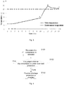
- a horizontal axis represents a time axis (unit: min)
- a longitudinal axis represents a temperature axis (unit: DEG C)
- a dotted line represents the environment temperature
- a broken line represents the tube temperature of the evaporator.
- the environment temperature is 25 DEG C
- a relative environment humidity is 80%
- a maximum time length of the first target time period is 3min
- a maximum time length of the second target time period is 5min
- the pre-set temperature difference is 15 DEG C
- the pre-set temperature difference limiting value is 5 DEG C.
- the first judgement module 201 judges that the tube temperature of the evaporator continuously rises and reaches the maximum value namely 29 DEG C.
- the second judgement module 202 judges that a temperature difference obtained by continuous rise of the tube temperature of the evaporator within the time period between the point A and the point B is 15 DEG C, and the temperature difference namely 15 DEG C is equal to the pre-set temperature difference namely 15 DEG C.
- Fig. 4 is a flowchart of a compressor over-load protection control method according to a first embodiment of the invention. As shown in Fig. 4 , the compressor over-load protection control method includes Step S101 to Step S103 as follows.
- Detecting the state of the compressor may refer to detecting whether the state of the compressor is a power-on state and a power-off state. It is important to note that in the embodiment of the invention, when the compressor is in the power-off state, the overall compressor is still in an electrified state. When the compressor is over-loaded, an exhaust temperature of the compressor will be very high. Once the exhaust temperature of the compressor is over-high, the compressor will be powered off. At this time, detecting the state of the compressor will refer to detecting that the state of the compressor is the power-off state. Otherwise, it will be detected that the state of the compressor is the power-on state.
- Detecting the state of the compressor may refer to detecting whether the compressor is in the power-on state or the power-off state by detecting a tube temperature of an evaporator. It is important to note that Step S101 is executed by a main controller for a dehumidifier and an air conditioner.
- Step S102 It is judged whether the compressor is under over-load protection.
- Step S101 is executed.
- Step S103 is executed.
- Step S103 Fluorine shortage protection is shielded.
- the fluorine shortage protection When it is judged that the compressor is under the over-load protection, the fluorine shortage protection is shielded. Otherwise, the fluorine shortage protection is not shielded, wherein shielding the fluorine shortage protection may be control logic for shielding the fluorine shortage protection.
- Fig. 5 is a flowchart of a compressor over-load protection control method according to a second embodiment of the invention. As shown in Fig. 5 , the method includes Step 201 to Step 206. The embodiment can be taken as a preferred implementation mode of the embodiment shown in Fig. 4 .
- Step S201 A tube temperature of an evaporator within a first target time period and an environment temperature and a tube temperature of the evaporator within a second target time period are detected.
- the first target time period and the second target time period are adjacent time periods, and the second target time period is behind the first target time period.
- a time length of the first target time period can be pre-set, and preferably, the time length of the first target time period can be pre-set as 3min.
- the step that the tube temperature of the evaporator within the first target time period is detected includes that: a first tube temperature of the evaporator at a first moment is detected, a second tube temperature of the evaporator at a second moment is detected, and a third tube temperature of the evaporator at a third moment is detected, wherein the first moment, the second moment and the third moment may be any three successive time points within the first target time period, and the first moment, the second moment and the third moment are arranged on a time axis according to a time sequence.
- the step that the tube temperature of the evaporator within the second target time period is detected includes that: a fourth tube temperature of the evaporator at a fourth moment is detected, and a fifth tube temperature of the evaporator at a fifth moment is detected, wherein the fourth moment and the fifth moment are any successive time points within the second target time period, and the fifth moment is behind the fourth moment.
- Step S202 It is judged whether the tube temperature within the first target time period continuously rises and reaches a maximum value.
- a first judgement module 201 judges that the tube temperature of the evaporator within the first target time period continuously rises. Furthermore, under a critical state, when the first tube temperature and the third tube temperature are smaller than the second tube temperature, it is judged that the tube temperature within the first target time period continuously rises and reaches the maximum value under the critical state. It is important to note that the second tube temperature corresponding to the second moment is a maximum temperature within the first target time period under the critical state. If it is judged that the tube temperature of the evaporator within the first target time period continuously rises and reaches the maximum value, Step S203 is executed, and otherwise, Step S201 is executed.
- Step S203 It is judged whether a temperature difference obtained by continuous rise of the tube temperature of the evaporator within the first target time period is greater than or equal to a pre-set temperature difference.
- Step S204 is executed, and otherwise, Step S201 is executed.
- Step S202 and Step S203 can be executed in a reverse sequence.
- Step S204 It is judged whether a difference between the environment temperature and the tube temperature of the evaporator within the second target time period is smaller than a pre-set temperature difference limiting value.
- Step S205 is executed, and otherwise, Step S201 is re-executed.
- a temperature difference between the fifth tube temperature and the fourth tube temperature can be calculated.
- the fifth tube temperature is smaller than the fourth tube temperature, namely when the temperature difference is less than 0 and the two tube temperatures are successive values, it is judged that the tube temperature of the evaporator within the second target time period continuously drops.
- Step S205 is executed, and Step S201 is re-executed.
- Step S205 It is determined that the compressor is under over-load protection.
- Step S206 is executed.
- Step S206 If the compressor is under the over-load protection, fluorine shortage protection is shielded.
- the fluorine shortage protection can be shielded by adopting the steps as follows.
- a pre-set over-load protection time period is obtained.
- the pre-set over-load protection time period can be set as 60min.
- the first target time period and the second target time period are removed from the pre-set over-load protection time period to determine a third target time period, wherein the first target time period, the second target time period and the third target time period are successive time periods, and the third target time period is behind the second target time period.
- the fluorine shortage protection is shielded within the third target time period, or the fluorine shortage protection is shielded within a certain time period extending from the third target time period.
- the third target time period is the last 52min of a certain hour.
- the fluorine shortage protection can be shielded within the last 52min of the certain hour or the fluorine shortage protection can be shielded between the last 52min of the certain hour and the first 10min of a next hour.
- a fluorine shortage protection stop command sent to the compressor is obtained, wherein the fluorine shortage protection stop command includes a first fluorine shortage protection stop command, a second fluorine shortage protection stop command and a third fluorine shortage protection stop command.
- the main controller sends the first fluorine shortage protection stop command to the compressor; when the fluorine shortage protection data is detected for the second time, the main controller sends the second fluorine shortage protection stop command to the compressor; and when the fluorine shortage protection data is detected for the third time, the main controller sends the third fluorine shortage protection stop command to the compressor.
- modules or all steps in the invention can be realized by using a general calculation apparatus, can be centralized on a single calculation apparatus or can be distributed on a network composed of a plurality of calculation apparatuses.
- they can be realized by using executable program codes of the calculation apparatuses.
- they can be stored in a storage apparatus and executed by the calculation apparatuses, or they are manufactured into each integrated circuit module respectively, or a plurality of modules or steps therein are manufactured into a single integrated circuit module.
- the invention is not limited to a combination of any specific hardware and software.
Landscapes
- Engineering & Computer Science (AREA)
- Mechanical Engineering (AREA)
- General Engineering & Computer Science (AREA)
- Physics & Mathematics (AREA)
- Thermal Sciences (AREA)
- Computer Hardware Design (AREA)
- Air Conditioning Control Device (AREA)
- Control Of Positive-Displacement Pumps (AREA)
Claims (12)
- Steuerungsverfahren für Verdichterüberlastschutz, wobei das Steuerungsverfahren für Verdichterüberlastschutz für einen Überlastschutz eines Entfeuchters und einer Klimaanlage konfiguriert ist, und jeder von dem Entfeuchter und der Klimaanlage einen Verdampfer und den Verdichter umfasst, wobei das Steuerungsverfahren für Verdichterüberlastschutz umfasst:Feststellen (S101), ob der Verdichter in einem eingeschalteten Zustand oder einem abgeschalteten Zustand ist, durch Feststellen einer Rohrtemperatur eines Verdampfers;Beurteilen (S102), dass der Verdichter sich unter Überlastschutz befindet, wenn der Verdichter im abgeschalteten Zustand ist und Beurteilen, dass der Verdichter sich nicht unter Überlastschutz befindet, wenn der Verdichter im eingeschalteten Zustand ist; undSichern (S103) des Fluormangelschutzes, wenn der Verdichter sich unter Überlastschutz befindet.
- Steuerungsverfahren für Verdichterüberlastschutz nach Anspruch 1, wobei Feststellen des Zustands des Verdichters umfasst:Feststellen (S201) einer Rohrtemperatur des Verdampfers innerhalb eines ersten Zielzeitraums und einer Umgebungstemperatur und einer Rohrtemperatur des Verdampfers innerhalb eines zweiten Zielzeitraums, wobei der erste Zielzeitraum und der zweite Zielzeitraum angrenzende Zeiträume sind, und der zweite Zielzeitraum sich hinter dem ersten Zielzeitraum befindet; undBeurteilen, ob der Verdichter sich unter Überlastschutz befindet, umfasst:Beurteilen (S202), ob die Rohrtemperatur innerhalb des ersten Zielzeitraums kontinuierlich steigt und einen Höchstwert erreicht; nachdem beurteilt ist, dass die Rohrtemperatur innerhalb des ersten Zielzeitraums kontinuierlich steigt und den Höchstwert erreicht,Beurteilen (S203), ob ein durch kontinuierlichen Anstieg der Rohrtemperatur innerhalb des ersten Zielzeitraums erfasster Temperaturunterschied größer oder gleich einem vorgegebenen Temperaturunterschied ist; nachdem beurteilt ist, dass der durch den kontinuierlichen Anstieg der Rohrtemperatur innerhalb des ersten Zielzeitraums erfasste Temperaturunterschied größer oder gleich dem vorgegebenen Temperaturunterschied ist,Beurteilen (S204), ob ein Unterschied zwischen der Umgebungstemperatur und der Rohrtemperatur innerhalb des zweiten Zielzeitraums kleiner ist als ein vorgegebener Temperaturunterschiedbegrenzungswert; und wenn beurteilt wird, dass der Unterschied zwischen der Umgebungstemperatur und der Rohrtemperatur innerhalb des zweiten Zielzeitraums kleiner ist als der vorgegebene Temperaturunterschiedbegrenzungswert,Bestimmen (S205), dass der Verdichter sich unter Überlastschutz befindet.
- Steuerungsverfahren für Verdichterüberlastschutz nach Anspruch 2, wobei
Feststellen der Rohrtemperatur des Verdampfers innerhalb des ersten Zielzeitraums umfasst:Feststellen einer ersten Rohrtemperatur des Verdampfers zu einem ersten Moment, Feststellen einer zweiten Rohrtemperatur des Verdampfers zu einem zweiten Moment, und Feststellen einer dritten Rohrtemperatur des Verdampfers zu einem dritten Moment,wobei der erste Moment, der zweite Moment und der dritte Moment jegliche aufeinanderfolgende Zeitpunkte innerhalb des ersten Zielzeitraums sind, der zweite Moment sich hinter dem ersten Moment und der dritte Moment sich hinter dem zweiten Moment befindet; undBeurteilen, ob die Rohrtemperatur innerhalb des ersten Zielzeitraums kontinuierlich steigt und den Höchstwert erreicht, umfasst:
Beurteilen, ob die Rohrtemperatur des Verdampfers innerhalb des ersten Zielzeitraums kontinuierlich steigt und den Höchstwert erreicht, durch Beurteilen eines Größenverhältnisses zwischen der ersten Rohrtemperatur, der zweiten Rohrtemperatur und der dritten Rohrtemperatur. - Steuerungsverfahren für Verdichterüberlastschutz nach Anspruch 2, wobei
Feststellen der Rohrtemperatur des Verdampfers innerhalb des zweiten Zielzeitraums umfasst:Feststellen einer vierten Rohrtemperatur des Verdampfers zu einem vierten Moment, und Feststellen einer fünften Rohrtemperatur des Verdampfers zu einem fünften Moment, wobei der vierte Moment und der fünfte Moment jegliche aufeinanderfolgende Zeitpunkte innerhalb des zweiten Zielzeitraums sind und der fünfte Moment sich hinter dem vierten Moment befindet; undBeurteilen, ob der Unterschied zwischen der Umgebungstemperatur und der Rohrtemperatur innerhalb des zweiten Zielzeitraums kleiner ist als der vorgegebene Temperaturunterschiedbegrenzungswert umfasst:Berechnen eines Temperaturunterschieds zwischen der fünften Rohrtemperatur und der vierten Rohrtemperatur; undBeurteilen, ob die Rohrtemperatur innerhalb des zweiten Zielzeitraums kontinuierlich fällt, durch Beurteilen, ob der Temperaturunterschied kleiner als 0 ist. - Steuerungsverfahren für Verdichterüberlastschutz nach Anspruch 2, wobei das Sichern des Fluormangelschutzes umfasst:Erfassen eines vorgegebenen Überlastschutz-Zeitraums;Entfernen des ersten Zielzeitraums und des zweiten Zielzeitraums aus dem vorgegebenen Überlastschutz-Zeitraum, um einem dritten Zielzeitraum festzustellen, wobei der dritte Zielzeitraum an den zweiten Zielzeitraum angrenzt und der dritte Zielzeitraum sich hinter dem zweiten Zielzeitraum befindet; undSichern des Fluormangelschutzes innerhalb des dritten Zielzeitraums.
- Steuerungsverfahren für Verdichterüberlastschutz nach Anspruch 5, wobei, bevor der Fluormangelschutz innerhalb des dritten Zielzeitraums gesichert wird, das Sichern des Fluormangelschutzes ferner umfasst:Erfassen eines an den Verdichter gesendeten Fluormangelschutz-Stoppbefehls, wobei der Fluormangelschutz-Stoppbefehl einen ersten Fluormangelschutz-Stoppbefehl, einen zweiten Fluormangelschutz-Stoppbefehl und einen dritten Fluormangelschutz-Stoppbefehl beinhaltet; undFestellen, ob ein Moment, zu dem der dritte Fluormangelschutz-Stoppbefehl gesendet wird, sich innerhalb des ersten Zielzeitraums oder des zweiten Zielzeitraums befindet,wobei, wenn festgestellt wird, dass der Moment, zu dem der dritte Fluormangelschutz-Stoppbefehl gesendet wird, sich nicht innerhalb des ersten Zielzeitraums oder des zweiten Zielzeitraums befindet, der Fluormangelschutz gesichert wird.
- Steuerungsvorrichtung für Verdichterüberlastschutz, wobei die Steuerungsvorrichtung für Verdichterüberlastschutz für einen Überlastschutz eines Entfeuchters und einer Klimaanlage konfiguriert ist, und jeder von dem Entfeuchter und der Klimaanlage einen Verdampfer und den Verdichter umfasst, wobei die Steuerungsvorrichtung für Verdichterüberlastschutz umfasst:eine Festelleinheit (10), die konfiguriert ist, um festzustellen, ob der Verdichter in einem eingeschalteten Zustand oder einem abgeschalteten Zustand ist, durch Feststellen einer Rohrtemperatur eines Verdampfers;eine Beurteilungseinheit (20), die konfiguriert ist, um zu beurteilen, dass der Verdichter sich unter Überlastschutz befindet, wenn der Verdichter im abgeschalteten Zustand ist und Beurteilen, dass der Verdichter sich nicht unter Überlastschutz befindet, wenn der Verdichter im eingeschalteten Zustand ist; undeine Sicherungseinheit (30), die konfiguriert ist, um Fluormangelschutz zu sichern, wenn der Verdichter sich unter Überlastschutz befindet.
- Steuerungsvorrichtung für Verdichterüberlastschutz nach Anspruch 7, wobei die Feststelleinheit (10) ferner konfiguriert ist, um eine Rohrtemperatur des Verdampfers innerhalb eines ersten Zielzeitraums und eine Umgebungstemperatur und eine Rohrtemperatur des Verdampfers innerhalb eines zweiten Zielzeitraums festzustellen, wobei der erste Zielzeitraum und der zweite Zielzeitraum angrenzende Zeiträume sind, und der zweite Zielzeitraum sich hinter dem ersten Zielzeitraum befindet; und
die Beurteilungseinheit (20) umfasst:ein erstes Beurteilungsmodul (201), das konfiguriert ist, um zu beurteilen, ob die Rohrtemperatur innerhalb des ersten Zielzeitraums kontinuierlich steigt und einen Höchstwert erreicht;ein zweites Beurteilungsmodul (202), das konfiguriert ist, um zu beurteilen, ob ein durch den kontinuierlichen Anstieg der Rohrtemperatur innerhalb des ersten Zielzeitraums erfasster Temperaturunterschied größer oder gleich einem vorgegebenen Temperaturunterschied ist, nachdem beurteilt ist, dass die Rohrtemperatur innerhalb des ersten Zielzeitraums kontinuierlich steigt und den Höchstwert erreicht;ein drittes Beurteilungsmodul (203), das konfiguriert ist, um zu beurteilen, ob ein Unterschied zwischen der Umgebungstemperatur und der Rohrtemperatur innerhalb des zweiten Zielzeitraums kleiner ist als ein vorgegebener Temperaturunterschiedbegrenzungswert, nachdem beurteilt ist, dass der durch den kontinuierlichen Anstieg der Rohrtemperatur innerhalb des ersten Zielzeitraums erfasste Temperaturunterschied größer oder gleich dem vorgegebenen Temperaturunterschied ist; undein erstes Bestimmungsmodul (204), das konfiguriert ist, um zu bestimmen, dass der Verdichter sich unter Überlastschutz befindet, wenn beurteilt wird, dass der Unterschied zwischen der Umgebungstemperatur und der Rohrtemperatur innerhalb des zweiten Zielzeitraums kleiner ist als der vorgegebene Temperaturunterschiedbegrenzungswert. - Steuerungsvorrichtung für Verdichterüberlastschutz nach Anspruch 8, wobei die Feststelleinheit (10) umfasst:ein erstes Feststellmodul, das konfiguriert ist, um eine erste Rohrtemperatur des Verdampfers zu einem ersten Moment festzustellen;ein zweites Feststellmodul, das konfiguriert ist, um eine zweite Rohrtemperatur des Verdampfers zu einem zweiten Moment festzustellen; undein drittes Feststellmodul, das konfiguriert ist, um eine dritte Rohrtemperatur des Verdampfers zu einem dritten Moment festzustellen,wobei der erste Moment, der zweite Moment und der dritte Moment jegliche aufeinanderfolgende Zeitpunkte innerhalb des ersten Zielzeitraums sind, der zweite Moment sich hinter dem ersten Moment befindet, der dritte Moment sich hinter dem zweiten Moment befindet und das erste Beurteilungsmodul konfiguriert ist, um zu beurteilen, ob die Rohrtemperatur des Verdampfers innerhalb des ersten Zielzeitraums kontinuierlich steigt und den Höchstwert erreicht, durch Beurteilen eines Größenverhältnisses zwischen der ersten Rohrtemperatur, der zweiten Rohrtemperatur und der dritten Rohrtem peratur.
- Steuerungsvorrichtung für Verdichterüberlastschutz nach Anspruch 8, wobei
die Feststelleinheit (10) ferner umfasst:ein viertes Feststellmodul, das konfiguriert ist, um eine vierte Rohrtemperatur des Verdampfers zu einem vierten Moment festzustellen; undein fünftes Feststellmodul, das konfiguriert ist, um eine fünfte Rohrtemperatur des Verdampfers zu einem fünften Moment festzustellen,wobei der vierte Moment und der fünfte Moment jegliche aufeinanderfolgende Zeitpunkte innerhalb des zweiten Zielzeitraums sind, und der fünfte Moment sich hinter dem vierten Moment befindet; unddas zweite Beurteilungsmodul umfasst:ein Berechnungssubmodul, das konfiguriert ist, um einen Temperaturunterschied zwischen der fünften Rohrtemperatur und der vierten Rohrtemperatur zu berechnen; undein Beurteilungssubmodul, das konfiguriert ist, um zu beurteilen, ob die Rohrtemperatur innerhalb des zweiten Zielzeitraums kontinuierlich fällt, durch Beurteilen, ob der Temperaturunterschied kleiner als 0 ist. - Steuerungsvorrichtung für Verdichterüberlastschutz nach Anspruch 8, wobei die Sicherungseinheit (30) umfasst:ein erstes Erfassungsmodul, das konfiguriert ist, um einen vorgegebenen Überlastschutz-Zeitraum zu erfassen;ein zweites Bestimmungsmodul, das konfiguriert ist, um den ersten Zielzeitraum und den zweiten Zielzeitraum aus dem vorgegebenen Überlastschutz-Zeitraum zu entfernen, um einem dritten Zielzeitraum festzustellen, wobei der dritte Zielzeitraum an den zweiten Zielzeitraum angrenzt und der dritte Zielzeitraum sich hinter dem zweiten Zielzeitraum befindet; undein Sicherungsmodul das konfiguriert ist, um den Fluormangelschutz innerhalb des dritten Zielzeitraums zu sichern.
- Steuerungsvorrichtung für Verdichterüberlastschutz nach Anspruch 11, wobei die Sicherungseinheit (30) ferner umfasst:ein zweites Erfassungsmodul, das konfiguriert ist, um, bevor der Fluormangelschutz innerhalb des dritten Zielzeitraums gesichert wird, einen an den Verdichter gesendeten Fluormangelschutz-Stoppbefehl zu erfassen, wobei der Fluormangelschutz-Stoppbefehl einen ersten Fluormangelschutz-Stoppbefehl, einen zweiten Fluormangelschutz-Stoppbefehl und einen dritten Fluormangelschutz-Stoppbefehl beinhaltet; undein sechtes Festellmodul, das konfiguriert ist, um festzustellen, ob ein Moment, zu dem der dritte Fluormangelschutz-Stoppbefehl gesendet wird, sich innerhalb des ersten Zielzeitraums oder des zweiten Zielzeitraums befindet,wobei die Sicherungseinheit ferner konfiguriert ist, um den Fluormangelschutz zu sichern, wenn festgestellt wird, dass der Moment, zu dem der dritte Fluormangelschutz-Stoppbefehl gesendet wird, sich nicht innerhalb des ersten Zielzeitraums oder des zweiten Zielzeitraums befindet.
Applications Claiming Priority (2)
| Application Number | Priority Date | Filing Date | Title |
|---|---|---|---|
| CN201310508782.5A CN104564638B (zh) | 2013-10-24 | 2013-10-24 | 压缩机过载保护控制方法和装置 |
| PCT/CN2014/088976 WO2015058666A1 (zh) | 2013-10-24 | 2014-10-20 | 压缩机过载保护控制方法和装置 |
Publications (3)
| Publication Number | Publication Date |
|---|---|
| EP3073115A1 EP3073115A1 (de) | 2016-09-28 |
| EP3073115A4 EP3073115A4 (de) | 2017-10-25 |
| EP3073115B1 true EP3073115B1 (de) | 2020-02-19 |
Family
ID=52992269
Family Applications (1)
| Application Number | Title | Priority Date | Filing Date |
|---|---|---|---|
| EP14855274.8A Active EP3073115B1 (de) | 2013-10-24 | 2014-10-20 | Steuerungsverfahren und -vorrichtung für verdichterüberlastschutz |
Country Status (5)
| Country | Link |
|---|---|
| US (1) | US10228174B2 (de) |
| EP (1) | EP3073115B1 (de) |
| CN (1) | CN104564638B (de) |
| ES (1) | ES2790575T3 (de) |
| WO (1) | WO2015058666A1 (de) |
Families Citing this family (9)
| Publication number | Priority date | Publication date | Assignee | Title |
|---|---|---|---|---|
| CN105180362B (zh) * | 2015-09-02 | 2018-01-23 | 珠海格力电器股份有限公司 | 压缩机过载保护控制方法和装置及定频空调器 |
| CN105066370B (zh) * | 2015-09-02 | 2018-04-17 | 珠海格力电器股份有限公司 | 压缩机过载保护控制方法和装置及空调器 |
| CN110398022B (zh) * | 2019-08-02 | 2020-07-31 | 宁波奥克斯电气股份有限公司 | 空调过载保护判断方法、装置和空调器 |
| CN112032930B (zh) * | 2020-08-17 | 2021-07-20 | 珠海格力电器股份有限公司 | 一种压缩机保护方法、装置、存储介质和电子设备 |
| US11710955B2 (en) * | 2021-01-22 | 2023-07-25 | Infineon Technologies Ag | Parameter threshold level based on signal from controller |
| CN113847703B (zh) * | 2021-10-29 | 2023-08-15 | 海信(广东)空调有限公司 | 除湿机的冷媒泄漏检测方法 |
| CN114216201B (zh) * | 2021-12-02 | 2024-03-22 | 珠海格力电器股份有限公司 | 定频空调的控制方法及定频空调 |
| CN115682369B (zh) * | 2022-11-03 | 2024-09-20 | 珠海格力电器股份有限公司 | 一种空调的控制方法、装置、空调和存储介质 |
| CN116146474B (zh) * | 2023-02-28 | 2026-02-27 | 美的集团股份有限公司 | 水泵控制方法、装置、家电设备及存储介质 |
Family Cites Families (12)
| Publication number | Priority date | Publication date | Assignee | Title |
|---|---|---|---|---|
| US5802862A (en) * | 1991-11-12 | 1998-09-08 | Eiermann; Kenneth L. | Method and apparatus for latent heat extraction with cooling coil freeze protection and complete recovery of heat of rejection in Dx systems |
| JPH09310942A (ja) * | 1996-05-23 | 1997-12-02 | Fujitsu General Ltd | 空気調和機の制御方法およびその装置 |
| JP2003051232A (ja) * | 2001-05-31 | 2003-02-21 | Mitsubishi Electric Corp | 過負荷保護装置、電動圧縮機及び冷凍空調装置 |
| KR100451233B1 (ko) * | 2002-03-16 | 2004-10-02 | 엘지전자 주식회사 | 왕복동식 압축기의 운전제어방법 |
| EP1538337B1 (de) * | 2003-12-02 | 2014-03-05 | Roland Weigel | Anordnung zum Überlastschutz und Verfahren zur Reduktion des Stromverbrauchs bei Netzspannungsschwankungen |
| US7424343B2 (en) * | 2004-08-11 | 2008-09-09 | Lawrence Kates | Method and apparatus for load reduction in an electric power system |
| JP2008209021A (ja) * | 2007-02-23 | 2008-09-11 | Mitsubishi Heavy Ind Ltd | マルチ型空気調和装置 |
| CN100587369C (zh) * | 2007-07-25 | 2010-02-03 | 宁波奥克斯空调有限公司 | 一种空调器的智能除霜方法 |
| CN101782262A (zh) * | 2009-11-23 | 2010-07-21 | 宁波奥克斯空调有限公司 | 用于空调器缺氟时的压缩机保护装置 |
| CN101929719B (zh) * | 2010-08-27 | 2012-07-18 | 宁波奥克斯空调有限公司 | 一种变频空调器缺氟时的压缩机保护方法 |
| CN101893310A (zh) * | 2010-08-31 | 2010-11-24 | 四川长虹空调有限公司 | 热泵空调器制热模式下防压缩机过载的控制方法 |
| CN103306962A (zh) * | 2013-07-05 | 2013-09-18 | 四川长虹空调有限公司 | 压缩机缺氟的保护方法及检测电路 |
-
2013
- 2013-10-24 CN CN201310508782.5A patent/CN104564638B/zh active Active
-
2014
- 2014-10-20 WO PCT/CN2014/088976 patent/WO2015058666A1/zh not_active Ceased
- 2014-10-20 ES ES14855274T patent/ES2790575T3/es active Active
- 2014-10-20 EP EP14855274.8A patent/EP3073115B1/de active Active
- 2014-10-20 US US15/031,845 patent/US10228174B2/en active Active
Non-Patent Citations (1)
| Title |
|---|
| None * |
Also Published As
| Publication number | Publication date |
|---|---|
| EP3073115A1 (de) | 2016-09-28 |
| US20160265828A1 (en) | 2016-09-15 |
| US10228174B2 (en) | 2019-03-12 |
| WO2015058666A1 (zh) | 2015-04-30 |
| CN104564638A (zh) | 2015-04-29 |
| EP3073115A4 (de) | 2017-10-25 |
| ES2790575T3 (es) | 2020-10-28 |
| CN104564638B (zh) | 2016-08-17 |
Similar Documents
| Publication | Publication Date | Title |
|---|---|---|
| US10228174B2 (en) | Compressor over-load protection control method and apparatus | |
| CN105180362B (zh) | 压缩机过载保护控制方法和装置及定频空调器 | |
| KR102356475B1 (ko) | 배터리의 충전 전압 데이터에 기반한 배터리 상태 추정 방법 및 장치 | |
| EP3211750B1 (de) | Verfahren und system zur dynamischen anpassung von batterieunterspannungsschutz | |
| RU2016116026A (ru) | Способ и аппарат для обработки пакета установки приложения | |
| CA2768357A1 (en) | Wind turbine generator system fault processing method and system | |
| CN109539474B (zh) | 空调控制方法和装置 | |
| CN104454386A (zh) | 风力发电机组结冰控制方法和装置 | |
| US20140191695A1 (en) | Thermal protection method and system to maximize availability of electric drive system | |
| CN110398022B (zh) | 空调过载保护判断方法、装置和空调器 | |
| CN105066370A (zh) | 压缩机过载保护控制方法和装置及空调器 | |
| CN114064430A (zh) | 一种计算机温度异常处理方法及系统 | |
| JP2023534249A5 (de) | ||
| CN102679495A (zh) | 空调补偿启动方法 | |
| CN104819786B (zh) | 空调器中变频模块的温度传感器的检测方法及装置 | |
| US20150377506A1 (en) | Management apparatus and method of managing air-conditioning apparatus | |
| CN106403173A (zh) | 一种空调器冷媒泄露的判定方法及装置 | |
| CN103723051B (zh) | 一种分布式电池管理系统的状态同步及跟踪方法 | |
| CN111550900A (zh) | 一种空调器应急控制方法 | |
| CN108899595B (zh) | 一种电池的温度检测方法、装置和设备 | |
| KR101695575B1 (ko) | 고장 검출 로직을 포함하는 위성체 | |
| WO2014208932A1 (ko) | 계통 전압 이상에 따른 계통 연계 인버터의 과전류 억제장치 및 방법 | |
| KR101717201B1 (ko) | 전지의 방전 제어 기능을 가지는 디바이스 | |
| KR20190108377A (ko) | 전기 안전 상황 감지 방법 | |
| CN105241034B (zh) | 用于空调器的控制方法及控制装置 |
Legal Events
| Date | Code | Title | Description |
|---|---|---|---|
| PUAI | Public reference made under article 153(3) epc to a published international application that has entered the european phase |
Free format text: ORIGINAL CODE: 0009012 |
|
| 17P | Request for examination filed |
Effective date: 20160520 |
|
| AK | Designated contracting states |
Kind code of ref document: A1 Designated state(s): AL AT BE BG CH CY CZ DE DK EE ES FI FR GB GR HR HU IE IS IT LI LT LU LV MC MK MT NL NO PL PT RO RS SE SI SK SM TR |
|
| AX | Request for extension of the european patent |
Extension state: BA ME |
|
| RAP1 | Party data changed (applicant data changed or rights of an application transferred) |
Owner name: GREE ELECTRIC APPLIANCES, INC. OF ZHUHAI |
|
| DAX | Request for extension of the european patent (deleted) | ||
| A4 | Supplementary search report drawn up and despatched |
Effective date: 20170926 |
|
| RIC1 | Information provided on ipc code assigned before grant |
Ipc: F25B 49/02 20060101ALI20170918BHEP Ipc: F24F 3/14 20060101ALI20170918BHEP Ipc: F24F 11/00 20060101ALI20170918BHEP Ipc: F04B 49/06 20060101AFI20170918BHEP Ipc: F04B 49/02 20060101ALI20170918BHEP |
|
| RIC1 | Information provided on ipc code assigned before grant |
Ipc: F04B 49/06 20060101AFI20190731BHEP Ipc: F25B 49/02 20060101ALI20190731BHEP Ipc: F04B 49/10 20060101ALI20190731BHEP Ipc: F04B 51/00 20060101ALI20190731BHEP |
|
| GRAP | Despatch of communication of intention to grant a patent |
Free format text: ORIGINAL CODE: EPIDOSNIGR1 |
|
| STAA | Information on the status of an ep patent application or granted ep patent |
Free format text: STATUS: GRANT OF PATENT IS INTENDED |
|
| INTG | Intention to grant announced |
Effective date: 20190920 |
|
| GRAS | Grant fee paid |
Free format text: ORIGINAL CODE: EPIDOSNIGR3 |
|
| GRAA | (expected) grant |
Free format text: ORIGINAL CODE: 0009210 |
|
| STAA | Information on the status of an ep patent application or granted ep patent |
Free format text: STATUS: THE PATENT HAS BEEN GRANTED |
|
| AK | Designated contracting states |
Kind code of ref document: B1 Designated state(s): AL AT BE BG CH CY CZ DE DK EE ES FI FR GB GR HR HU IE IS IT LI LT LU LV MC MK MT NL NO PL PT RO RS SE SI SK SM TR |
|
| REG | Reference to a national code |
Ref country code: CH Ref legal event code: EP |
|
| REG | Reference to a national code |
Ref country code: DE Ref legal event code: R096 Ref document number: 602014061336 Country of ref document: DE |
|
| REG | Reference to a national code |
Ref country code: AT Ref legal event code: REF Ref document number: 1235279 Country of ref document: AT Kind code of ref document: T Effective date: 20200315 |
|
| REG | Reference to a national code |
Ref country code: IE Ref legal event code: FG4D |
|
| REG | Reference to a national code |
Ref country code: NL Ref legal event code: MP Effective date: 20200219 |
|
| PG25 | Lapsed in a contracting state [announced via postgrant information from national office to epo] |
Ref country code: RS Free format text: LAPSE BECAUSE OF FAILURE TO SUBMIT A TRANSLATION OF THE DESCRIPTION OR TO PAY THE FEE WITHIN THE PRESCRIBED TIME-LIMIT Effective date: 20200219 Ref country code: FI Free format text: LAPSE BECAUSE OF FAILURE TO SUBMIT A TRANSLATION OF THE DESCRIPTION OR TO PAY THE FEE WITHIN THE PRESCRIBED TIME-LIMIT Effective date: 20200219 Ref country code: NO Free format text: LAPSE BECAUSE OF FAILURE TO SUBMIT A TRANSLATION OF THE DESCRIPTION OR TO PAY THE FEE WITHIN THE PRESCRIBED TIME-LIMIT Effective date: 20200519 |
|
| REG | Reference to a national code |
Ref country code: LT Ref legal event code: MG4D |
|
| PG25 | Lapsed in a contracting state [announced via postgrant information from national office to epo] |
Ref country code: BG Free format text: LAPSE BECAUSE OF FAILURE TO SUBMIT A TRANSLATION OF THE DESCRIPTION OR TO PAY THE FEE WITHIN THE PRESCRIBED TIME-LIMIT Effective date: 20200519 Ref country code: GR Free format text: LAPSE BECAUSE OF FAILURE TO SUBMIT A TRANSLATION OF THE DESCRIPTION OR TO PAY THE FEE WITHIN THE PRESCRIBED TIME-LIMIT Effective date: 20200520 Ref country code: HR Free format text: LAPSE BECAUSE OF FAILURE TO SUBMIT A TRANSLATION OF THE DESCRIPTION OR TO PAY THE FEE WITHIN THE PRESCRIBED TIME-LIMIT Effective date: 20200219 Ref country code: LV Free format text: LAPSE BECAUSE OF FAILURE TO SUBMIT A TRANSLATION OF THE DESCRIPTION OR TO PAY THE FEE WITHIN THE PRESCRIBED TIME-LIMIT Effective date: 20200219 Ref country code: SE Free format text: LAPSE BECAUSE OF FAILURE TO SUBMIT A TRANSLATION OF THE DESCRIPTION OR TO PAY THE FEE WITHIN THE PRESCRIBED TIME-LIMIT Effective date: 20200219 Ref country code: IS Free format text: LAPSE BECAUSE OF FAILURE TO SUBMIT A TRANSLATION OF THE DESCRIPTION OR TO PAY THE FEE WITHIN THE PRESCRIBED TIME-LIMIT Effective date: 20200619 |
|
| PG25 | Lapsed in a contracting state [announced via postgrant information from national office to epo] |
Ref country code: NL Free format text: LAPSE BECAUSE OF FAILURE TO SUBMIT A TRANSLATION OF THE DESCRIPTION OR TO PAY THE FEE WITHIN THE PRESCRIBED TIME-LIMIT Effective date: 20200219 |
|
| REG | Reference to a national code |
Ref country code: ES Ref legal event code: FG2A Ref document number: 2790575 Country of ref document: ES Kind code of ref document: T3 Effective date: 20201028 |
|
| PG25 | Lapsed in a contracting state [announced via postgrant information from national office to epo] |
Ref country code: CZ Free format text: LAPSE BECAUSE OF FAILURE TO SUBMIT A TRANSLATION OF THE DESCRIPTION OR TO PAY THE FEE WITHIN THE PRESCRIBED TIME-LIMIT Effective date: 20200219 Ref country code: DK Free format text: LAPSE BECAUSE OF FAILURE TO SUBMIT A TRANSLATION OF THE DESCRIPTION OR TO PAY THE FEE WITHIN THE PRESCRIBED TIME-LIMIT Effective date: 20200219 Ref country code: SM Free format text: LAPSE BECAUSE OF FAILURE TO SUBMIT A TRANSLATION OF THE DESCRIPTION OR TO PAY THE FEE WITHIN THE PRESCRIBED TIME-LIMIT Effective date: 20200219 Ref country code: EE Free format text: LAPSE BECAUSE OF FAILURE TO SUBMIT A TRANSLATION OF THE DESCRIPTION OR TO PAY THE FEE WITHIN THE PRESCRIBED TIME-LIMIT Effective date: 20200219 Ref country code: SK Free format text: LAPSE BECAUSE OF FAILURE TO SUBMIT A TRANSLATION OF THE DESCRIPTION OR TO PAY THE FEE WITHIN THE PRESCRIBED TIME-LIMIT Effective date: 20200219 Ref country code: LT Free format text: LAPSE BECAUSE OF FAILURE TO SUBMIT A TRANSLATION OF THE DESCRIPTION OR TO PAY THE FEE WITHIN THE PRESCRIBED TIME-LIMIT Effective date: 20200219 Ref country code: RO Free format text: LAPSE BECAUSE OF FAILURE TO SUBMIT A TRANSLATION OF THE DESCRIPTION OR TO PAY THE FEE WITHIN THE PRESCRIBED TIME-LIMIT Effective date: 20200219 Ref country code: PT Free format text: LAPSE BECAUSE OF FAILURE TO SUBMIT A TRANSLATION OF THE DESCRIPTION OR TO PAY THE FEE WITHIN THE PRESCRIBED TIME-LIMIT Effective date: 20200712 |
|
| REG | Reference to a national code |
Ref country code: AT Ref legal event code: MK05 Ref document number: 1235279 Country of ref document: AT Kind code of ref document: T Effective date: 20200219 |
|
| REG | Reference to a national code |
Ref country code: DE Ref legal event code: R097 Ref document number: 602014061336 Country of ref document: DE |
|
| PLBE | No opposition filed within time limit |
Free format text: ORIGINAL CODE: 0009261 |
|
| STAA | Information on the status of an ep patent application or granted ep patent |
Free format text: STATUS: NO OPPOSITION FILED WITHIN TIME LIMIT |
|
| 26N | No opposition filed |
Effective date: 20201120 |
|
| PG25 | Lapsed in a contracting state [announced via postgrant information from national office to epo] |
Ref country code: AT Free format text: LAPSE BECAUSE OF FAILURE TO SUBMIT A TRANSLATION OF THE DESCRIPTION OR TO PAY THE FEE WITHIN THE PRESCRIBED TIME-LIMIT Effective date: 20200219 Ref country code: IT Free format text: LAPSE BECAUSE OF FAILURE TO SUBMIT A TRANSLATION OF THE DESCRIPTION OR TO PAY THE FEE WITHIN THE PRESCRIBED TIME-LIMIT Effective date: 20200219 |
|
| PG25 | Lapsed in a contracting state [announced via postgrant information from national office to epo] |
Ref country code: PL Free format text: LAPSE BECAUSE OF FAILURE TO SUBMIT A TRANSLATION OF THE DESCRIPTION OR TO PAY THE FEE WITHIN THE PRESCRIBED TIME-LIMIT Effective date: 20200219 Ref country code: SI Free format text: LAPSE BECAUSE OF FAILURE TO SUBMIT A TRANSLATION OF THE DESCRIPTION OR TO PAY THE FEE WITHIN THE PRESCRIBED TIME-LIMIT Effective date: 20200219 |
|
| REG | Reference to a national code |
Ref country code: CH Ref legal event code: PL |
|
| GBPC | Gb: european patent ceased through non-payment of renewal fee |
Effective date: 20201020 |
|
| PG25 | Lapsed in a contracting state [announced via postgrant information from national office to epo] |
Ref country code: LU Free format text: LAPSE BECAUSE OF NON-PAYMENT OF DUE FEES Effective date: 20201020 Ref country code: MC Free format text: LAPSE BECAUSE OF FAILURE TO SUBMIT A TRANSLATION OF THE DESCRIPTION OR TO PAY THE FEE WITHIN THE PRESCRIBED TIME-LIMIT Effective date: 20200219 |
|
| REG | Reference to a national code |
Ref country code: BE Ref legal event code: MM Effective date: 20201031 |
|
| PG25 | Lapsed in a contracting state [announced via postgrant information from national office to epo] |
Ref country code: LI Free format text: LAPSE BECAUSE OF NON-PAYMENT OF DUE FEES Effective date: 20201031 Ref country code: GB Free format text: LAPSE BECAUSE OF NON-PAYMENT OF DUE FEES Effective date: 20201020 Ref country code: BE Free format text: LAPSE BECAUSE OF NON-PAYMENT OF DUE FEES Effective date: 20201031 Ref country code: CH Free format text: LAPSE BECAUSE OF NON-PAYMENT OF DUE FEES Effective date: 20201031 |
|
| PG25 | Lapsed in a contracting state [announced via postgrant information from national office to epo] |
Ref country code: IE Free format text: LAPSE BECAUSE OF NON-PAYMENT OF DUE FEES Effective date: 20201020 |
|
| PG25 | Lapsed in a contracting state [announced via postgrant information from national office to epo] |
Ref country code: TR Free format text: LAPSE BECAUSE OF FAILURE TO SUBMIT A TRANSLATION OF THE DESCRIPTION OR TO PAY THE FEE WITHIN THE PRESCRIBED TIME-LIMIT Effective date: 20200219 Ref country code: MT Free format text: LAPSE BECAUSE OF FAILURE TO SUBMIT A TRANSLATION OF THE DESCRIPTION OR TO PAY THE FEE WITHIN THE PRESCRIBED TIME-LIMIT Effective date: 20200219 Ref country code: CY Free format text: LAPSE BECAUSE OF FAILURE TO SUBMIT A TRANSLATION OF THE DESCRIPTION OR TO PAY THE FEE WITHIN THE PRESCRIBED TIME-LIMIT Effective date: 20200219 |
|
| PG25 | Lapsed in a contracting state [announced via postgrant information from national office to epo] |
Ref country code: MK Free format text: LAPSE BECAUSE OF FAILURE TO SUBMIT A TRANSLATION OF THE DESCRIPTION OR TO PAY THE FEE WITHIN THE PRESCRIBED TIME-LIMIT Effective date: 20200219 Ref country code: AL Free format text: LAPSE BECAUSE OF FAILURE TO SUBMIT A TRANSLATION OF THE DESCRIPTION OR TO PAY THE FEE WITHIN THE PRESCRIBED TIME-LIMIT Effective date: 20200219 |
|
| P01 | Opt-out of the competence of the unified patent court (upc) registered |
Effective date: 20230530 |
|
| PGFP | Annual fee paid to national office [announced via postgrant information from national office to epo] |
Ref country code: FR Payment date: 20250909 Year of fee payment: 12 |
|
| PGFP | Annual fee paid to national office [announced via postgrant information from national office to epo] |
Ref country code: DE Payment date: 20251020 Year of fee payment: 12 |
|
| PGFP | Annual fee paid to national office [announced via postgrant information from national office to epo] |
Ref country code: ES Payment date: 20251114 Year of fee payment: 12 |