EP3072668B2 - Verfahren und vorrichtung zum verbinden von profilstücken - Google Patents
Verfahren und vorrichtung zum verbinden von profilstücken Download PDFInfo
- Publication number
- EP3072668B2 EP3072668B2 EP16160542.3A EP16160542A EP3072668B2 EP 3072668 B2 EP3072668 B2 EP 3072668B2 EP 16160542 A EP16160542 A EP 16160542A EP 3072668 B2 EP3072668 B2 EP 3072668B2
- Authority
- EP
- European Patent Office
- Prior art keywords
- profile
- tool
- machining
- milling
- processing
- Prior art date
- Legal status (The legal status is an assumption and is not a legal conclusion. Google has not performed a legal analysis and makes no representation as to the accuracy of the status listed.)
- Active
Links
Images



Classifications
-
- B—PERFORMING OPERATIONS; TRANSPORTING
- B29—WORKING OF PLASTICS; WORKING OF SUBSTANCES IN A PLASTIC STATE IN GENERAL
- B29C—SHAPING OR JOINING OF PLASTICS; SHAPING OF MATERIAL IN A PLASTIC STATE, NOT OTHERWISE PROVIDED FOR; AFTER-TREATMENT OF THE SHAPED PRODUCTS, e.g. REPAIRING
- B29C65/00—Joining or sealing of preformed parts, e.g. welding of plastics materials; Apparatus therefor
- B29C65/02—Joining or sealing of preformed parts, e.g. welding of plastics materials; Apparatus therefor by heating, with or without pressure
- B29C65/18—Joining or sealing of preformed parts, e.g. welding of plastics materials; Apparatus therefor by heating, with or without pressure using heated tools
- B29C65/20—Joining or sealing of preformed parts, e.g. welding of plastics materials; Apparatus therefor by heating, with or without pressure using heated tools with direct contact, e.g. using "mirror"
- B29C65/2053—Joining or sealing of preformed parts, e.g. welding of plastics materials; Apparatus therefor by heating, with or without pressure using heated tools with direct contact, e.g. using "mirror" characterised by special ways of bringing the welding mirrors into position
- B29C65/2061—Joining or sealing of preformed parts, e.g. welding of plastics materials; Apparatus therefor by heating, with or without pressure using heated tools with direct contact, e.g. using "mirror" characterised by special ways of bringing the welding mirrors into position by sliding
- B29C65/2069—Joining or sealing of preformed parts, e.g. welding of plastics materials; Apparatus therefor by heating, with or without pressure using heated tools with direct contact, e.g. using "mirror" characterised by special ways of bringing the welding mirrors into position by sliding with an angle with respect to the plane comprising the parts to be joined
-
- B—PERFORMING OPERATIONS; TRANSPORTING
- B23—MACHINE TOOLS; METAL-WORKING NOT OTHERWISE PROVIDED FOR
- B23C—MILLING
- B23C3/00—Milling particular work; Special milling operations; Machines therefor
- B23C3/12—Trimming or finishing edges, e.g. deburring welded corners
- B23C3/128—Trimming or finishing edges of doors and windows
-
- B—PERFORMING OPERATIONS; TRANSPORTING
- B29—WORKING OF PLASTICS; WORKING OF SUBSTANCES IN A PLASTIC STATE IN GENERAL
- B29C—SHAPING OR JOINING OF PLASTICS; SHAPING OF MATERIAL IN A PLASTIC STATE, NOT OTHERWISE PROVIDED FOR; AFTER-TREATMENT OF THE SHAPED PRODUCTS, e.g. REPAIRING
- B29C65/00—Joining or sealing of preformed parts, e.g. welding of plastics materials; Apparatus therefor
- B29C65/02—Joining or sealing of preformed parts, e.g. welding of plastics materials; Apparatus therefor by heating, with or without pressure
- B29C65/18—Joining or sealing of preformed parts, e.g. welding of plastics materials; Apparatus therefor by heating, with or without pressure using heated tools
- B29C65/20—Joining or sealing of preformed parts, e.g. welding of plastics materials; Apparatus therefor by heating, with or without pressure using heated tools with direct contact, e.g. using "mirror"
- B29C65/2092—Joining or sealing of preformed parts, e.g. welding of plastics materials; Apparatus therefor by heating, with or without pressure using heated tools with direct contact, e.g. using "mirror" and involving the use of a facer
-
- B—PERFORMING OPERATIONS; TRANSPORTING
- B29—WORKING OF PLASTICS; WORKING OF SUBSTANCES IN A PLASTIC STATE IN GENERAL
- B29C—SHAPING OR JOINING OF PLASTICS; SHAPING OF MATERIAL IN A PLASTIC STATE, NOT OTHERWISE PROVIDED FOR; AFTER-TREATMENT OF THE SHAPED PRODUCTS, e.g. REPAIRING
- B29C65/00—Joining or sealing of preformed parts, e.g. welding of plastics materials; Apparatus therefor
- B29C65/78—Means for handling the parts to be joined, e.g. for making containers or hollow articles, e.g. means for handling sheets, plates, web-like materials, tubular articles, hollow articles or elements to be joined therewith; Means for discharging the joined articles from the joining apparatus
- B29C65/7802—Positioning the parts to be joined, e.g. aligning, indexing or centring
-
- B—PERFORMING OPERATIONS; TRANSPORTING
- B29—WORKING OF PLASTICS; WORKING OF SUBSTANCES IN A PLASTIC STATE IN GENERAL
- B29C—SHAPING OR JOINING OF PLASTICS; SHAPING OF MATERIAL IN A PLASTIC STATE, NOT OTHERWISE PROVIDED FOR; AFTER-TREATMENT OF THE SHAPED PRODUCTS, e.g. REPAIRING
- B29C65/00—Joining or sealing of preformed parts, e.g. welding of plastics materials; Apparatus therefor
- B29C65/78—Means for handling the parts to be joined, e.g. for making containers or hollow articles, e.g. means for handling sheets, plates, web-like materials, tubular articles, hollow articles or elements to be joined therewith; Means for discharging the joined articles from the joining apparatus
- B29C65/7841—Holding or clamping means for handling purposes
-
- B—PERFORMING OPERATIONS; TRANSPORTING
- B29—WORKING OF PLASTICS; WORKING OF SUBSTANCES IN A PLASTIC STATE IN GENERAL
- B29C—SHAPING OR JOINING OF PLASTICS; SHAPING OF MATERIAL IN A PLASTIC STATE, NOT OTHERWISE PROVIDED FOR; AFTER-TREATMENT OF THE SHAPED PRODUCTS, e.g. REPAIRING
- B29C66/00—General aspects of processes or apparatus for joining preformed parts
- B29C66/01—General aspects dealing with the joint area or with the area to be joined
- B29C66/02—Preparation of the material, in the area to be joined, prior to joining or welding
- B29C66/022—Mechanical pre-treatments, e.g. reshaping
- B29C66/0224—Mechanical pre-treatments, e.g. reshaping with removal of material
- B29C66/02241—Cutting, e.g. by using waterjets, or sawing
-
- B—PERFORMING OPERATIONS; TRANSPORTING
- B29—WORKING OF PLASTICS; WORKING OF SUBSTANCES IN A PLASTIC STATE IN GENERAL
- B29C—SHAPING OR JOINING OF PLASTICS; SHAPING OF MATERIAL IN A PLASTIC STATE, NOT OTHERWISE PROVIDED FOR; AFTER-TREATMENT OF THE SHAPED PRODUCTS, e.g. REPAIRING
- B29C66/00—General aspects of processes or apparatus for joining preformed parts
- B29C66/01—General aspects dealing with the joint area or with the area to be joined
- B29C66/05—Particular design of joint configurations
- B29C66/10—Particular design of joint configurations particular design of the joint cross-sections
- B29C66/11—Joint cross-sections comprising a single joint-segment, i.e. one of the parts to be joined comprising a single joint-segment in the joint cross-section
- B29C66/116—Single bevelled joints, i.e. one of the parts to be joined being bevelled in the joint area
- B29C66/1162—Single bevel to bevel joints, e.g. mitre joints
-
- B—PERFORMING OPERATIONS; TRANSPORTING
- B29—WORKING OF PLASTICS; WORKING OF SUBSTANCES IN A PLASTIC STATE IN GENERAL
- B29C—SHAPING OR JOINING OF PLASTICS; SHAPING OF MATERIAL IN A PLASTIC STATE, NOT OTHERWISE PROVIDED FOR; AFTER-TREATMENT OF THE SHAPED PRODUCTS, e.g. REPAIRING
- B29C66/00—General aspects of processes or apparatus for joining preformed parts
- B29C66/50—General aspects of joining tubular articles; General aspects of joining long products, i.e. bars or profiled elements; General aspects of joining single elements to tubular articles, hollow articles or bars; General aspects of joining several hollow-preforms to form hollow or tubular articles
- B29C66/51—Joining tubular articles, profiled elements or bars; Joining single elements to tubular articles, hollow articles or bars; Joining several hollow-preforms to form hollow or tubular articles
- B29C66/52—Joining tubular articles, bars or profiled elements
- B29C66/524—Joining profiled elements
- B29C66/5243—Joining profiled elements for forming corner connections, e.g. for making window frames or V-shaped pieces
- B29C66/52431—Joining profiled elements for forming corner connections, e.g. for making window frames or V-shaped pieces with a right angle, e.g. for making L-shaped pieces
-
- B—PERFORMING OPERATIONS; TRANSPORTING
- B29—WORKING OF PLASTICS; WORKING OF SUBSTANCES IN A PLASTIC STATE IN GENERAL
- B29C—SHAPING OR JOINING OF PLASTICS; SHAPING OF MATERIAL IN A PLASTIC STATE, NOT OTHERWISE PROVIDED FOR; AFTER-TREATMENT OF THE SHAPED PRODUCTS, e.g. REPAIRING
- B29C66/00—General aspects of processes or apparatus for joining preformed parts
- B29C66/70—General aspects of processes or apparatus for joining preformed parts characterised by the composition, physical properties or the structure of the material of the parts to be joined; Joining with non-plastics material
- B29C66/72—General aspects of processes or apparatus for joining preformed parts characterised by the composition, physical properties or the structure of the material of the parts to be joined; Joining with non-plastics material characterised by the structure of the material of the parts to be joined
- B29C66/723—General aspects of processes or apparatus for joining preformed parts characterised by the composition, physical properties or the structure of the material of the parts to be joined; Joining with non-plastics material characterised by the structure of the material of the parts to be joined being multi-layered
-
- B—PERFORMING OPERATIONS; TRANSPORTING
- B29—WORKING OF PLASTICS; WORKING OF SUBSTANCES IN A PLASTIC STATE IN GENERAL
- B29C—SHAPING OR JOINING OF PLASTICS; SHAPING OF MATERIAL IN A PLASTIC STATE, NOT OTHERWISE PROVIDED FOR; AFTER-TREATMENT OF THE SHAPED PRODUCTS, e.g. REPAIRING
- B29C66/00—General aspects of processes or apparatus for joining preformed parts
- B29C66/70—General aspects of processes or apparatus for joining preformed parts characterised by the composition, physical properties or the structure of the material of the parts to be joined; Joining with non-plastics material
- B29C66/72—General aspects of processes or apparatus for joining preformed parts characterised by the composition, physical properties or the structure of the material of the parts to be joined; Joining with non-plastics material characterised by the structure of the material of the parts to be joined
- B29C66/725—General aspects of processes or apparatus for joining preformed parts characterised by the composition, physical properties or the structure of the material of the parts to be joined; Joining with non-plastics material characterised by the structure of the material of the parts to be joined being hollow-walled or honeycombs
- B29C66/7252—General aspects of processes or apparatus for joining preformed parts characterised by the composition, physical properties or the structure of the material of the parts to be joined; Joining with non-plastics material characterised by the structure of the material of the parts to be joined being hollow-walled or honeycombs hollow-walled
- B29C66/72523—General aspects of processes or apparatus for joining preformed parts characterised by the composition, physical properties or the structure of the material of the parts to be joined; Joining with non-plastics material characterised by the structure of the material of the parts to be joined being hollow-walled or honeycombs hollow-walled multi-channelled or multi-tubular
-
- B—PERFORMING OPERATIONS; TRANSPORTING
- B29—WORKING OF PLASTICS; WORKING OF SUBSTANCES IN A PLASTIC STATE IN GENERAL
- B29C—SHAPING OR JOINING OF PLASTICS; SHAPING OF MATERIAL IN A PLASTIC STATE, NOT OTHERWISE PROVIDED FOR; AFTER-TREATMENT OF THE SHAPED PRODUCTS, e.g. REPAIRING
- B29C2793/00—Shaping techniques involving a cutting or machining operation
- B29C2793/0009—Cutting out
-
- B—PERFORMING OPERATIONS; TRANSPORTING
- B29—WORKING OF PLASTICS; WORKING OF SUBSTANCES IN A PLASTIC STATE IN GENERAL
- B29C—SHAPING OR JOINING OF PLASTICS; SHAPING OF MATERIAL IN A PLASTIC STATE, NOT OTHERWISE PROVIDED FOR; AFTER-TREATMENT OF THE SHAPED PRODUCTS, e.g. REPAIRING
- B29C66/00—General aspects of processes or apparatus for joining preformed parts
- B29C66/01—General aspects dealing with the joint area or with the area to be joined
- B29C66/02—Preparation of the material, in the area to be joined, prior to joining or welding
- B29C66/024—Thermal pre-treatments
- B29C66/0246—Cutting or perforating, e.g. burning away by using a laser or using hot air
-
- B—PERFORMING OPERATIONS; TRANSPORTING
- B29—WORKING OF PLASTICS; WORKING OF SUBSTANCES IN A PLASTIC STATE IN GENERAL
- B29C—SHAPING OR JOINING OF PLASTICS; SHAPING OF MATERIAL IN A PLASTIC STATE, NOT OTHERWISE PROVIDED FOR; AFTER-TREATMENT OF THE SHAPED PRODUCTS, e.g. REPAIRING
- B29C66/00—General aspects of processes or apparatus for joining preformed parts
- B29C66/01—General aspects dealing with the joint area or with the area to be joined
- B29C66/32—Measures for keeping the burr form under control; Avoiding burr formation; Shaping the burr
- B29C66/324—Avoiding burr formation
-
- B—PERFORMING OPERATIONS; TRANSPORTING
- B29—WORKING OF PLASTICS; WORKING OF SUBSTANCES IN A PLASTIC STATE IN GENERAL
- B29C—SHAPING OR JOINING OF PLASTICS; SHAPING OF MATERIAL IN A PLASTIC STATE, NOT OTHERWISE PROVIDED FOR; AFTER-TREATMENT OF THE SHAPED PRODUCTS, e.g. REPAIRING
- B29C66/00—General aspects of processes or apparatus for joining preformed parts
- B29C66/50—General aspects of joining tubular articles; General aspects of joining long products, i.e. bars or profiled elements; General aspects of joining single elements to tubular articles, hollow articles or bars; General aspects of joining several hollow-preforms to form hollow or tubular articles
- B29C66/51—Joining tubular articles, profiled elements or bars; Joining single elements to tubular articles, hollow articles or bars; Joining several hollow-preforms to form hollow or tubular articles
- B29C66/52—Joining tubular articles, bars or profiled elements
- B29C66/524—Joining profiled elements
- B29C66/5243—Joining profiled elements for forming corner connections, e.g. for making window frames or V-shaped pieces
-
- B—PERFORMING OPERATIONS; TRANSPORTING
- B29—WORKING OF PLASTICS; WORKING OF SUBSTANCES IN A PLASTIC STATE IN GENERAL
- B29L—INDEXING SCHEME ASSOCIATED WITH SUBCLASS B29C, RELATING TO PARTICULAR ARTICLES
- B29L2031/00—Other particular articles
- B29L2031/001—Profiled members, e.g. beams, sections
- B29L2031/003—Profiled members, e.g. beams, sections having a profiled transverse cross-section
- B29L2031/005—Profiled members, e.g. beams, sections having a profiled transverse cross-section for making window frames
-
- E—FIXED CONSTRUCTIONS
- E06—DOORS, WINDOWS, SHUTTERS, OR ROLLER BLINDS IN GENERAL; LADDERS
- E06B—FIXED OR MOVABLE CLOSURES FOR OPENINGS IN BUILDINGS, VEHICLES, FENCES OR LIKE ENCLOSURES IN GENERAL, e.g. DOORS, WINDOWS, BLINDS, GATES
- E06B3/00—Window sashes, door leaves, or like elements for closing wall or like openings; Layout of fixed or moving closures, e.g. windows in wall or like openings; Features of rigidly-mounted outer frames relating to the mounting of wing frames
- E06B3/96—Corner joints or edge joints for windows, doors, or the like frames or wings
- E06B3/9604—Welded or soldered joints
- E06B3/9608—Mitre joints
Definitions
- the invention relates to a method for connecting profile pieces that meet at an angle, in particular plastic profile pieces, to form a welded frame or partial frame, in particular a window or door frame.
- the current state of the art proceeds as follows: First, the profile bars are sawn to size and mitre, whereby a certain tolerance in the length and angle of the mitre is accepted or taken into account.
- the profile bars are then placed in a welding machine in order to weld the adjacently positioned profile bars in the corners, at the miter or connecting surfaces that meet at an angle, usually a right angle (but without limiting the invention or the state of the art to this).
- the thermoplastic behavior of the plastic material of the profile is usually used for the welding process. It is important to ensure that the length tolerance accepted at the beginning is selected in such a way that, on the one hand, a stable weld is created, but on the other hand, there is not too much material. which has to be melted (or burned off) and then leads to an annoying weld bead.
- the fully welded frame or partial frame is placed in a so-called plastering machine, in which the corner connection, the miter surface or miter line (that is the connecting line of the two abutting profiles running around the corner connection) is finished.
- a so-called plastering machine in which the corner connection, the miter surface or miter line (that is the connecting line of the two abutting profiles running around the corner connection) is finished.
- this involves removing the weld bead, which affects the visual appearance and also the function of the window (if the weld bead is located in a groove for a sealing profile or the like, for example).
- Profiles are now known in the state of the art that have a rounded outer profile (in cross-section). Cutting off or removing the weld bead in this rounded area is a laborious process. It is also important to ensure that when plastering, i.e. removing a weld bead, a film laminated to the plastic profile, for example one that shows a wood decor, is not damaged.
- the document WO 2014/122572 A1 discloses a method for welding profile elements made of plastic material.
- the document DE 303 97 33 A1 discloses a method for butt welding thermoplastic hollow profile rods and a device for carrying out the same.
- the invention therefore has the task of improving the previously described state of the art.
- the cleverness of the invention lies in the fact that it has been recognized that optimal preparation of the miter or connecting surfaces, ideally shortly before the profile pieces are welded together, minimizes, if not completely prevents, the formation of a welding bead. It is advantageous to use the dimensional accuracy or dimensional stability that is already provided for during production (the finished frame or partial frame must have the correct final dimensions). This means that the position of the heating mirrors that are intended for welding the profile bars are arranged precisely, which is achieved by the appropriate adjustability of the machine. The profile bars are clamped for welding. They are then already in the correct position and, before the melting and welding actually takes place, the processing step is carried out as described in order to compensate for or reduce the tolerances.
- Step (iii) takes place after step (i), since reliable connection, i.e. welding of the profile pieces, then requires clamping of the profile pieces.
- the tolerance to be compensated is initially the length tolerance of the profile bar.
- the compensation of at least one length tolerance in at least one connecting surface of the profile pieces that extends perpendicularly to a frame plane is understood to mean the distance between the connecting surfaces that delimit the profile piece.
- a profile bar that was sawn off too generously led to considerable melting or burning and therefore to the formation of a large, voluminous weld bead that had to be removed accordingly. If the length is narrowed to an optimized tolerance, which is done by the machining step according to the invention, no larger weld bead (if any) can be formed during the subsequent welding due to a lack of material.
- the proposal according to the invention is not limited to the length tolerance, but also concerns the tolerance of the angular position (angular position tolerance) of the connecting surface(s) or the mitre surface(s). This is because a bevelled mitre surface leads to This also led to a material overhang which, similar to a profile bar that had been sawn off too generously, had to be burned off when connecting.
- the position of the miter surface in the finished frame or partial frame can be defined exactly:
- the connecting surface or miter surface is perpendicular to the frame plane and usually encloses half the corner angle with the longitudinal extension of the adjoining profile bars.
- the frame plane is in turn defined by the profile bars, which, each viewed individually, define at least one longitudinal extension and, arranged at an angle to one another, span a plane between them, the frame plane.
- the precise compensation takes place in the clamping position of the profile bars, as it is also used for welding afterwards.
- this saves re-clamping the profile bar and thus setup time.
- such a variant ensures that the successive processing steps can be carried out in an optimized manner in terms of their positioning, so that the dimensional accuracy is high and the tolerances can be compensated so closely that the formation of a welded connection is reduced to a level optimized for the production of an effective connection. Ideally, only a negligible or no weld bead will then form.
- processing tools for separating profile material from the profile piece can be, for example, processing tools that produce chips, but it is also possible to use a laser or water jet cutter as a processing tool for this processing.
- the latter processing methods laser or water jet cutter
- a machining tool that produces chips is understood to mean, for example, a milling cutter or a milling tool in general, without, however, reducing the machining tool according to the invention to this specific tool. Machining tools with defined or specific cutting edges as well as with indefinite cutting edges can be used according to the inventive approach. The dimensional accuracy ultimately results from the special design of the tool and is therefore controllable. The removal of chips is therefore carried out, for example, by milling, planing, grinding or similar.
- the object according to the invention is also achieved by a processing machine for connecting profile pieces that meet at an angle, in particular plastic profile pieces, to form welded frames or partial frames, in particular window or door frames, which is characterized in particular by the fact that a processing tool for separating profile material is provided, which has at least one processing surface aligned parallel to a connecting surface and is intended for at least partial, in particular full-surface separation of profile material on the connecting surface, wherein the processing machine is intended to carry out the method according to the invention.
- a milling tool is provided as the processing tool, which is formed from two milling disks that are symmetrically aligned in opposite directions to one another and are implemented as face milling cutters, wherein the two milling disks are spaced apart by a spacer, wherein the milling tool is designed as a double milling cutter and simultaneously processes both ends of two inserted profile pieces, wherein a belt drive engages the spacer.
- machining step which is carried out by the machining tool, is carried out in a processing machine, which is actually intended for
- the processing machine according to the proposal is part of a processing system that is used to manufacture window frames or partial frames. It is intended that the processing step that eliminates the tolerance takes place shortly before the welding of the profile pieces, whereby the tolerance eliminating step (separation of profile material) is provided in a separate processing machine, or together with the welding of the profile pieces to form frames or frame parts.
- the proposal advantageously provides for a length measurement to determine the length tolerance of the profile pieces before or after clamping in order to determine an actual value for the length.
- the length tolerance results from a comparison of the actually measured actual value of the length in comparison with the processing parameters or the order, since the actual profile length has to take into account a significant excess for the formation of the welded joint.
- the invention comprises at least two variants of how the length tolerance can be compensated:
- a first variant the actual length of the profile piece is determined using a separate length measurement and stored in a suitable manner. This actual length is then compared with the nominal length/nominal value (in terms of data, for example in the control system) and this results in an excess to be removed by the machining tool, which is cleverly divided between the two ends of the profile piece, whereby the connecting surface or miter surface is then machined on both sides, which then also leads to the connection surface being arranged at the correct angle.
- the excess to be machined is then shown on a display, for example, and the profile bar is then positioned and clamped to the displayed dimension, which can be done manually, by the operator, or automatically. This approach is particularly recommended when only one corner connection can be machined at a time in a relatively simple machining machine. Such a machining machine is also known as a single-head machine.
- multi-head machines which include two or four machining heads, for example, several corners are machined in the same way in one machining step.
- the machining heads essentially consisting of a clamping device, the heating mirror and the machining tool
- the path measuring systems length measuring systems
- drives which allow the machining heads to be positioned precisely to the machining dimension.
- the machining heads are advantageously positioned on the connecting surface and a profile bar that is inserted between two adjacent machining heads that are at the correct machining dimension can be easily centered between these two machining heads.
- the angular position of the connecting surfaces relative to the frame plane and a compensation of tolerances takes place by machining the connecting surfaces with at least one machining tool.
- the frame plane is defined by the two profile bars.
- the angular position can be determined directly.
- the angular position can also be determined indirectly, via planes specified by the processing machine.
- the plane specified by the support surfaces on which the profiles are placed and clamped is suitable.
- the processing plane defined in this way is parallel to the frame plane.
- the working plane within which the corresponding machining takes place must then be distinguished from the processing plane. These working planes are specified, for example, by the orientation of the heating mirror or the processing tool.
- the procedure according to the invention is therefore not only possible by compensating the (length) tolerance, but can also be carried out in the same way by correcting/compensating the tolerance in the angular position of the connecting surface. Both variants are part of the invention.
- the angle tolerance is usually automatically eliminated, i.e. corrected, when the profile piece is clamped and machined to the correct length.
- the arrangement is such that the machining surface created by the machining tool is ideally parallel to the surface of the heating mirror that creates the connection, thus enabling a mechanically optimal connection with minimal burnt-off of plastic material.
- step (ii) takes place immediately before step (iii), in particular that no re-clamping of the profile pieces is provided between step (ii) and step (iii).
- Such a process is effective because no additional set-up times are required for re-clamping. It also enables highly precise machining because the machining tool and the heating mirror are guided precisely in the machining surface and this geometric relationship between the material-separating process step and the welding is not broken.
- the method includes a step of fixing the profile piece, wherein the fixing is provided before or after the centering and/or length measurement.
- the fixing i.e. the clamping of the profile piece, can take place at different times, which underlines the high variability of this proposal.
- the connecting surface(s) can be machined over the entire surface or only part of it. Only part of the connecting surface (or an area on the connecting surface) can be machined if the processing tool used provides a processing length that is smaller than the height or another dimension of the cross-sectional area or miter surface of the profile.
- the processing tool used provides a processing length that is smaller than the height or another dimension of the cross-sectional area or miter surface of the profile.
- Such a design of the processing tool may mean that the miter surface has to be machined several times with the processing tool, each time at different positions.
- the connecting surface(s) are only to be separated on the outer profile areas, in particular the profile webs that border the profile. It is clear that this proposal does not involve full-surface removal, but only corresponding parts of the connecting surface are removed. This proposal is based on the knowledge that this avoids/reduces the formation of a visually disturbing, external welding bead and at the same time a welding bead can certainly form in the inner area, but this is not disturbing because it is inside the profile or frame and therefore not visible from the outside. This has the advantage that a larger volume of material is available in the inner area for fusion or welding, thus resulting in an overall more stable connection of the two profile elements to be welded, while at the same time the smallest, most minimal or even no welding bead is formed. It is clear that here the entire profile web width of the external profile webs is removed to the acceptable tolerance.
- the proposal advantageously provides that in step (i) the profile pieces are moved at least along a first axis (X) running parallel to the frame plane and/or a second axis (Y) perpendicular thereto and also running in the frame plane.
- an adjustable feed rate and/or the feed path of the profile pieces is provided.
- step (ii) a compensation of tolerances with regard to the length of the profile pieces and the angular position of the connecting surfaces is carried out at the same time.
- step (ii) is carried out several times, in particular until the at least one nominal value is reached within the tolerance.
- the length of the profile piece is determined in particular via a distance measuring system.
- Determining the length using the distance measuring system or centering the profile bar that has not yet been machined in the processing machine is cleverly done before clamping. However, it is also possible to first clamp the profile piece, then determine the length, then position the processing tool(s) based on this information and then carry out the material-separating processing.
- the angular position of the connecting surface relative to the frame plane is determined by an angle measuring system.
- step (ii) an alignment of the position of the profile pieces to each other is carried out.
- the clamping position of the profile is checked again before machining. It can It can happen that the profiles are tilted or twisted around their longitudinal axis (because they were inserted incorrectly, for example) and then the lateral surfaces of the profiles to be welded do not meet.
- a corresponding check can be carried out using switches, optically (light barrier) or through more complex image processing and evaluation. If a corresponding incorrect position is detected, the control system interrupts further processing and requires a realignment of the position of the profile pieces, which is communicated to the operator via a display, for example, and the operator then manually reinserts the profile bars.
- the control sequence can be designed so that the profiles are automatically removed and reinserted again.
- step (ii) the profile pieces are aligned so as to allow the end faces (connecting surfaces) to be joined congruently.
- the core of the invention aligns the two profile pieces according to the frame plane defined by the profile pieces. Theoretically, however, it is also possible for the profile pieces to have a correctly sawn connecting surface and for the profile pieces to be aligned to this.
- the proposal advantageously provides for the machining tool to be displaced along an axis that is parallel, vertical or inclined relative to the machining plane.
- the machining plane is determined by the machining machine and the plane in which the frame parts are clamped; of course, the aim is for the frame plane to be parallel to the machining plane.
- step (iii) the approach of a heating mirror to the connecting surfaces takes place by moving the heating mirror along an axis that is parallel, perpendicular or inclined to the processing plane.
- the displacement of the machining tool and/or the heating mirror takes place in a plane parallel to the frame plane, from above or below the frame plane.
- the amount of material removed is selected such that the lowest possible burn-off is achieved with the highest possible stability of the welded joint and the formation of a particularly visible weld bead on the connecting surfaces or in the frame plane is avoided or minimized.
- the separated profile material e.g. the chips
- suctioned off with the suction taking place in particular via or through the machining tool.
- the suction takes place cleverly during the material-burning machining, or afterwards, preferably before the profile pieces are welded, so that the separated material residues, e.g. the chips, do not impair the welding.
- the rotating machining tool develops a suitable wind flow or suction that carries the chips away from the connecting surface in a controlled way.
- Such a design makes it possible to carry out this machining alongside the welding and thus ultimately to carry out two normally mutually exclusive machining steps in one machining machine.
- steps (ii) and (iii) are carried out in separate devices and/or spatially separated, in particular in order to minimize contamination of the welding process with lifted chips.
- a receiving groove of the profile piece is machined with a chip-producing machining tool.
- the receiving groove extends in the longitudinal direction of the profile piece and is used, for example, to accommodate a seal, a fitting or the like. After welding, the receiving groove may be filled with molten plastic material, which is why it is advantageous to carry out special preparatory work here.
- the machining tool proposed here is, for example, combined with the machining tool intended for machining the connecting surface, with a face milling cutter for the connecting surface and an end mill for the receiving groove, for example. Since such a combined machining tool is movable in the working plane, i.e. can be positioned in a driven and controlled manner, the various machining tasks can be processed using an appropriate sequence control.
- this proposal also includes the option of using two different, separate machining tools for these two machining tasks.
- each of these tools has its own tool carrier or a shared tool carrier.
- the machining tools can be moved and positioned in a controlled manner using the tool carrier(s).
- step (ii) is carried out simultaneously on the connecting surfaces of two adjacently positioned profile pieces that are subsequently to be welded together.
- Such a procedure has several advantages: The profile pieces are already in the clamped state, as if they were to be welded. They are in the correct position and, at the same time, the tolerance is compensated for by the processing step (ii), with the effects stated above.
- the accuracy of the machine in particular the position of the working plane in which machining takes place, can be precisely controlled in the machine and leads to the desired machining result.
- a feed of the profile pieces and/or the processing tool is provided, wherein a preferably movable feed device is provided which aligns the profile pieces.
- the alignment is carried out both in terms of length and, if necessary, in terms of angle. Both possible alignments are carried out by the feed device.
- the proposal advantageously provides that the machining tool is arranged so as to be movable, in particular so as to be linearly displaceable.
- the machining tool can be positioned so as to be movable and in a controlled manner in a plane that is parallel to the working plane.
- the processing tool is arranged so as to be displaceable, in particular raising, lowering or pivoting, relative to a processing plane, with the processing machine providing a guide, in particular a guide rail or a guideway. Furthermore, it is also provided that the processing tool is deflectable; this applies in particular to the variant of the proposal in which laser or water jet cutting is provided as the processing tool.
- At least one, in particular two, preferably four processing tool(s) is/are provided.
- a control device is provided for the movement of the processing tool(s).
- a suction device associated with the processing tool is provided.
- the milling tool is designed in such a way that when the milling cutters provided in the milling tool rotate, a suction flow is formed, through which the lifted milling chips are carried away from the profile pieces and fed to a suction device or a housing surrounding the milling tool.
- the milling tool is provided with a brush ring.
- the diameter of this brush ring is larger than the diameter of the milling tool.
- the brush ring cleverly surrounds the milling tool on all sides, with the bristles of the brush protruding from the processing plane of the tool.
- the advantage of such a design is that the brush ring creates a variable cover that prevents the detached chips from being randomly distributed in the processing machine.
- the bristles of the brush ring lie against the profile piece and are bent slightly if necessary, thus creating a protective curtain.
- the detached chips hit the inside of the brush ring, where they lose some, if not most, of their kinetic energy because they are slowed down by the elastic bristles.
- the brush ring also improves the performance of the vacuum cleaner, as the brush ring represents a resistance to the air flow, and the air flow is then directed at a higher speed, elsewhere and is more effective.
- the proposal advantageously provides that tolerances with regard to the length of the profile pieces and/or the angular position of the connecting surfaces are compensated by the machining tool.
- the processing machine also has a heating mirror. It is provided that the heating mirror simultaneously heats and plasticizes both connecting surfaces of the adjacent profile pieces. The joining, the welding, then takes place.
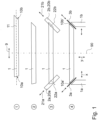
- step 1 the profile bar 1 is placed on a support, which is characterized in particular by a central axis 90.
- the profile bar 1 is described by a longitudinal axis 11 and has connecting surfaces 10a and 10b at its respective ends, which were obtained by sawing off a bar.
- the profile bar/profile piece 1 is to become part of a rectangular frame. Therefore, the connecting surfaces 10a and 10b should enclose a miter angle with the longitudinal axis 11 of 45°, which the left connecting surface 10a obviously does not have.
- the profile bar 1 is also not centered with respect to the central axis 90.
- step 2 the profile piece 1 is now positioned centered with respect to the central axis 90, which was achieved by a centering-positioning movement 9 which is parallel to the longitudinal axis 11.
- step 3 the profile piece 1 is then machined at the end by the machining tool 2.
- the machining tool 2 is designed as a milling tool 20, the left connecting surface 10a is machined by the milling tool 20a, which rotates about a rotation axis 22a.
- the machining tool 2a, 20a can be moved and positioned in a controlled manner along the double arrow 21a (in a working plane that is perpendicular to the frame plane).
- the working plane encloses the desired miter angle of 45° with the longitudinal axis 11.
- the arrangement is symmetrical with respect to the central axis 90, the right side has the same reference numerals that end in "b".
- the tolerance is compensated by milling off the end projections.
- New, machined connecting surfaces 10a' on the left side and 10b' on the right side are formed. These connecting surfaces 10a' and 10b' now have the correct miter angle and also an optimized, acceptable length tolerance.
- step 4 the other profile pieces 1a and 1b, which are connected at right angles, are indicated on the left and right.
- the heating mirror 3a and 3b is already located between the respective connecting surfaces, which were processed one after the other or simultaneously as described in step 3 and now have the correct miter angle, and the profile pieces 1, 1a, 1b are then adjusted in the known manner along the X, Y axes, which lie in the frame plane.
- the heating mirrors 3a, 3b are removed and the profile pieces are then joined and welded as usual.
- the embodiment shown here is a so-called 2-head machine, but the same can also be carried out in a so-called 4-head machine.
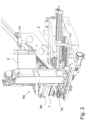
- FIG. 2 the basic arrangement of the profile pieces 1, 1a on the processing machine is shown.
- the section selected here shows a processing head of the processing machine, which has a clamping device 4a, 4b for each inserted profile piece 1, 1a as well as the processing tool 2 and the heating mirror 3, which are mounted and guided in the working plane so that they can be moved and positioned in a controlled manner.
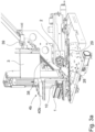
- Figure 3a is the front clamping device 4b (after Figure 2 ) and the associated profile piece 1a are hidden to increase clarity.
- the connecting surface 10 of the profile piece 1 is clearly visible, the clamping plate 40b is offset upwards, the profile piece 1 is not shown clamped here.
- a guide track 38 is provided for the heating mirror 3, which runs in the working plane or parallel to it.
- the heating mirror 3 has a carriage 39, which can be positioned on the guide track 38 in a controlled manner.
- a corresponding drive is of course also provided for this. It is easy to see that the guide track 38 forms an acute angle with the frame plane (and the processing plane of the processing machine running parallel to it), whereby a feed movement of the heating mirror 3 takes place from diagonally above to diagonally below. This is a clever arrangement of the heating mirror 3, since it is permanently heated and in this position is away from the connecting surface 10 and does not cause any interference.
- the heating mirror 3 in the Figure 3a shown position into a housing or cover and is thus protected from any flying chips that may be generated by the processing tool 2. This reliably prevents the chips from contaminating the heating surface of the heating mirror 3 and thus negatively affecting the subsequent welding process.
- the machining tool 2 also has a carriage 29 that can be positioned on a guide track 28 in a controlled manner. A drive is also provided for this.
- the guide track 28 is also located in the working plane or runs parallel to it. In the embodiment shown here, the machining tool 2 is located below the heating mirror 3 and is moved parallel to the frame plane (machining plane). The two movements of the heating mirror 3 and the machining tool 2 take place independently of one another or are coupled, for example also coupled by the control system. They thus reach the gap between the connecting surfaces to be joined without collision.
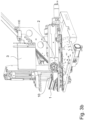
- Figure 4 shows a detail from a slightly different perspective, with the profile piece 1 shown here in a shortened form to increase clarity. It is clearly visible that the machining tool 2 has advanced far enough forward to machine the connecting surface 10.
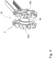
- FIG. 5 shows an embodiment of the machining tool 2 according to the invention.
- the machining tool 2 is designed as a milling tool 20, which is formed from two milling disks 23a and 23b, which are symmetrically aligned in opposite directions to one another and are implemented as face milling cutters.
- the two milling disks 23a and 23b are spaced apart by a spacer 26.
- a belt drive engages the spacer 26.
- the milling tool 2 is designed in such a way that during operation, i.e. during rotation, it generates an air flow that allows a guided discharge of the generated chips.
- FIG 6 the machining situation of the machining tool 2 between the two profile pieces 1, 1a is shown.
- the profile pieces 1, 1a are each clamped by triangular clamping plates 40a, 40b of the clamping devices 4a, 4b and thus fixed and held.
- a small area of the profile pieces 1, 1a protrudes at the end over the chipboards 40a, 40b and the machining tool 2 shown here has already machined the connecting surfaces, these are marked with 10aa' and 10a'.
- the arrangement is selected such that the milling tool 2, as a double milling cutter, simultaneously machines both ends of the inserted profile bars 1, 1a.
- FIG 8 Another embodiment of the machining tool 2, a milling tool 20, is shown.
- the basic structure of the milling tool 20 is the same as that according to Figure 5
- a small end mill 24a and 24b are arranged concentrically on the milling discs 23a and 23b, each on the outside, which is used in particular for additional machining tasks, for example in a receiving groove 12 of the profile bar 1.
- Figure 9 is shown.
- FIG. 9 The processing tool 2 used corresponds to the one in Figure 8 shown and described.
- the machining tool 2 is guided in such a way that the central end mill 24 only machines the profile piece 1 in certain places, namely in the receiving groove 12 or only the outer walls 19a, 19b, 19c, 19d of the profile bar 1. Therefore, the milling tool 20, machining tool 2 cannot cover the connecting surface 10 of the profile piece 1 over its entire surface, but only partially, which leads to a circular movement or U-shaped movement of the machining tool 2. Therefore, it is advantageous that the machining tool 2, 20 can be moved and positioned in the machining plane in at least two dimensions.
Landscapes
- Engineering & Computer Science (AREA)
- Mechanical Engineering (AREA)
- Milling Processes (AREA)
Priority Applications (1)
| Application Number | Priority Date | Filing Date | Title |
|---|---|---|---|
| PL16160542.3T PL3072668T5 (pl) | 2015-03-24 | 2016-03-15 | Sposób i urządzenie dla łączenia odcinków profili |
Applications Claiming Priority (1)
| Application Number | Priority Date | Filing Date | Title |
|---|---|---|---|
| DE102015104446 | 2015-03-24 |
Publications (3)
| Publication Number | Publication Date |
|---|---|
| EP3072668A1 EP3072668A1 (de) | 2016-09-28 |
| EP3072668B1 EP3072668B1 (de) | 2018-05-09 |
| EP3072668B2 true EP3072668B2 (de) | 2024-12-11 |
Family
ID=55696904
Family Applications (1)
| Application Number | Title | Priority Date | Filing Date |
|---|---|---|---|
| EP16160542.3A Active EP3072668B2 (de) | 2015-03-24 | 2016-03-15 | Verfahren und vorrichtung zum verbinden von profilstücken |
Country Status (3)
| Country | Link |
|---|---|
| EP (1) | EP3072668B2 (pl) |
| DE (1) | DE102016104806A1 (pl) |
| PL (1) | PL3072668T5 (pl) |
Families Citing this family (6)
| Publication number | Priority date | Publication date | Assignee | Title |
|---|---|---|---|---|
| US20200122408A1 (en) * | 2018-10-23 | 2020-04-23 | Patrick Terence Greller | High speed and no excess weld flash vinyl welder |
| DE102018133638A1 (de) * | 2018-12-27 | 2020-07-02 | Urban Gmbh & Co. Maschinenbau Kg | Verfahren und Vorrichtung für das Verschweißen von Profilstäben |
| DE102020113022A1 (de) * | 2020-05-13 | 2021-11-18 | Urban Gesellschaft mit beschränkter Haftung & Co. Maschinenbau Kommanditgesellschaft | Fräskopf, Bearbeitungsmaschine und Verfahren zum Betreiben einer Bearbeitungsmaschine |
| CN112959676B (zh) * | 2021-02-07 | 2024-03-29 | 西安伦宇门窗幕墙工程有限公司 | 一种塑钢窗框用拼接设备及其工艺 |
| DE102021006421A1 (de) | 2021-12-30 | 2023-07-06 | Urban Gesellschaft mit beschränkter Haftung & Co. Maschinenbau Kommanditgesellschaft | Fräseranordnung |
| CN120322324A (zh) * | 2022-11-29 | 2025-07-15 | 斯图尔茨机械制造有限公司 | 用于制造型材连接部的方法和设备 |
Family Cites Families (8)
| Publication number | Priority date | Publication date | Assignee | Title |
|---|---|---|---|---|
| US3186891A (en) | 1962-05-14 | 1965-06-01 | Gen Motors Corp | Apparatus for joining thermoplastic elements |
| DE3039733A1 (de) | 1980-10-21 | 1982-05-19 | Gebrüder Kömmerling Kunststoffwerke GmbH, 6780 Pirmasens | Verfahren zum stumpfverschweissen von thermoplastischen kunststoff-hohlprofilstaeben und vorrichtung zu dessen durchfuehrung |
| AT2466U1 (de) | 1997-06-18 | 1998-11-25 | Technoplast Kunststofftechnik | Vorrichtung zum gleichzeitigen verschweissen von mindestens vier auf gehrung geschnittenen profilabschnitten |
| DE20109451U1 (de) | 2001-04-12 | 2002-08-22 | Urban GmbH & Co. Maschinenbau KG, 87700 Memmingen | Vorrichtung zum Bearbeiten von Kunststoffprofilen für Fensterrahmen o.dgl. |
| CN107009633A (zh) | 2012-03-07 | 2017-08-04 | 格拉夫协同有限公司 | 用于焊接塑料材料、特别是pvc的型材构件的设备 |
| ITMO20130024A1 (it) | 2013-02-05 | 2014-08-06 | Graf Synergy Srl | Metodo e dispositivo per la saldatura di profilati in materiale plastico, in particolare pvc |
| EP3116704B1 (en) | 2014-03-12 | 2020-02-19 | Kaban, Salim | Burr-free pvc profile corner welding machine |
| TR201412334A2 (tr) * | 2014-10-21 | 2015-04-21 | Salim Kaban | Çapaksız pvc profil köşe kaynak makinesi. |
-
2016
- 2016-03-15 PL PL16160542.3T patent/PL3072668T5/pl unknown
- 2016-03-15 EP EP16160542.3A patent/EP3072668B2/de active Active
- 2016-03-15 DE DE102016104806.2A patent/DE102016104806A1/de active Pending
Also Published As
| Publication number | Publication date |
|---|---|
| PL3072668T5 (pl) | 2025-04-28 |
| EP3072668A1 (de) | 2016-09-28 |
| PL3072668T3 (pl) | 2018-10-31 |
| EP3072668B1 (de) | 2018-05-09 |
| DE102016104806A1 (de) | 2016-11-24 |
Similar Documents
| Publication | Publication Date | Title |
|---|---|---|
| EP3072668B1 (de) | Verfahren und vorrichtung zum verbinden von profilstücken | |
| EP3674065B1 (de) | Verfahren und vorrichtung für das verschweissen von profilstäben | |
| EP3072615A1 (de) | Fräskopf | |
| DE102019109294B4 (de) | Verfahren zum Verschweißen von Profilstäben | |
| EP1125670B1 (de) | Verputzvorrichtung, insbesondere Schweissraupenputzmaschine | |
| EP1537970B1 (de) | Verputzvorrichtung | |
| WO2015158537A1 (de) | Verfahren und vorrichtung zum lasergestützten trennen eines werkstücks | |
| EP2639022B1 (de) | Eckenputzvorrichtung | |
| EP0909602A1 (de) | Verputzvorrichtung für Fenster- oder Türrahmen | |
| EP3795339A1 (de) | Vorrichtung und verfahren zur entfernung von material ausserhalb der schweisszone | |
| DE2210814A1 (de) | Vorrichtung zum entfernen des an der stossfuge zwischen miteinander verschweissten profilstaeben aus schweissbarem kunststoff entstehenden schweisswulstes | |
| DE102006055286B4 (de) | Reibrührschweißvorrichtung mit einem Reibrührschweißkopf und einer absenkbaren Schweißunterlage sowie Verfahren | |
| DE2726382B2 (de) | Vorrichtung zum Bohren und Ausschneiden oder Fräsen eines Bauteiles aus einem plattenförmigen Werkstück aus Holz o.dgl | |
| DE4415305C2 (de) | Verfahren zur Herstellung einer Werkzeugmaschine | |
| EP3017923B1 (de) | Anlage zur herstellung oder herstellung und behandlung von glasleisten sowie verfahren unter verwendung einer solchen anlage | |
| DE2415006C3 (de) | Verfahren zur Herstellung von Fensterrahmen mit Glashalteleiste aus Holz und Vorrichtung zur Durchführung des Verfahrens | |
| DE2513620A1 (de) | Vorrichtung zur eckenbearbeitung von kunststoffprofilrahmen | |
| DE4219088A1 (de) | Verfahren und Vorrichtung zum Bearbeiten der Schweißraupen oder dergleichen eines Kunststoff-Fensterrahmens | |
| EP4667194A1 (de) | Vorrichtung und verfahren zur herstellung einer profilverbindung | |
| EP3736113B1 (de) | Vorrichtung und verfahren für die herstellung eines elementes | |
| EP0618032A1 (de) | Vorrichtung zur Bearbeitung der Eckverbindungen von aus Kunststoffprofilen geschweissten Fenster- oder Türrahmen | |
| EP3575068B1 (de) | Vorrichtung und verfahren zum verbinden von profilteilen | |
| DE2236087C3 (de) | Vorrichtung zum Bearbeiten der Stoßsteilen von aus Profilen stumpfgeschweißten Teile | |
| DE102005062133A1 (de) | Verfahren zum Bearbeiten von Fensterrahmen | |
| DE3036630C2 (de) | Vorrichtung zum Abtragen der Schweißwülste an Eckverbindungen |
Legal Events
| Date | Code | Title | Description |
|---|---|---|---|
| PUAI | Public reference made under article 153(3) epc to a published international application that has entered the european phase |
Free format text: ORIGINAL CODE: 0009012 |
|
| AK | Designated contracting states |
Kind code of ref document: A1 Designated state(s): AL AT BE BG CH CY CZ DE DK EE ES FI FR GB GR HR HU IE IS IT LI LT LU LV MC MK MT NL NO PL PT RO RS SE SI SK SM TR |
|
| AX | Request for extension of the european patent |
Extension state: BA ME |
|
| STAA | Information on the status of an ep patent application or granted ep patent |
Free format text: STATUS: REQUEST FOR EXAMINATION WAS MADE |
|
| 17P | Request for examination filed |
Effective date: 20161130 |
|
| RBV | Designated contracting states (corrected) |
Designated state(s): AL AT BE BG CH CY CZ DE DK EE ES FI FR GB GR HR HU IE IS IT LI LT LU LV MC MK MT NL NO PL PT RO RS SE SI SK SM TR |
|
| STAA | Information on the status of an ep patent application or granted ep patent |
Free format text: STATUS: EXAMINATION IS IN PROGRESS |
|
| 17Q | First examination report despatched |
Effective date: 20170404 |
|
| GRAP | Despatch of communication of intention to grant a patent |
Free format text: ORIGINAL CODE: EPIDOSNIGR1 |
|
| STAA | Information on the status of an ep patent application or granted ep patent |
Free format text: STATUS: GRANT OF PATENT IS INTENDED |
|
| RIC1 | Information provided on ipc code assigned before grant |
Ipc: B29C 65/00 20060101ALI20180110BHEP Ipc: B29L 31/00 20060101ALN20180110BHEP Ipc: E06B 3/96 20060101ALI20180110BHEP Ipc: B29C 65/20 20060101AFI20180110BHEP Ipc: B23C 3/30 20060101ALI20180110BHEP Ipc: B29C 65/78 20060101ALI20180110BHEP |
|
| INTG | Intention to grant announced |
Effective date: 20180125 |
|
| GRAS | Grant fee paid |
Free format text: ORIGINAL CODE: EPIDOSNIGR3 |
|
| GRAA | (expected) grant |
Free format text: ORIGINAL CODE: 0009210 |
|
| STAA | Information on the status of an ep patent application or granted ep patent |
Free format text: STATUS: THE PATENT HAS BEEN GRANTED |
|
| AK | Designated contracting states |
Kind code of ref document: B1 Designated state(s): AL AT BE BG CH CY CZ DE DK EE ES FI FR GB GR HR HU IE IS IT LI LT LU LV MC MK MT NL NO PL PT RO RS SE SI SK SM TR |
|
| REG | Reference to a national code |
Ref country code: GB Ref legal event code: FG4D Free format text: NOT ENGLISH |
|
| REG | Reference to a national code |
Ref country code: CH Ref legal event code: EP Ref country code: AT Ref legal event code: REF Ref document number: 997199 Country of ref document: AT Kind code of ref document: T Effective date: 20180515 |
|
| REG | Reference to a national code |
Ref country code: IE Ref legal event code: FG4D Free format text: LANGUAGE OF EP DOCUMENT: GERMAN |
|
| REG | Reference to a national code |
Ref country code: DE Ref legal event code: R096 Ref document number: 502016001004 Country of ref document: DE |
|
| REG | Reference to a national code |
Ref country code: CH Ref legal event code: NV Representative=s name: ALDO ROEMPLER PATENTANWALT, CH |
|
| REG | Reference to a national code |
Ref country code: RO Ref legal event code: EPE |
|
| REG | Reference to a national code |
Ref country code: NL Ref legal event code: FP |
|
| REG | Reference to a national code |
Ref country code: LT Ref legal event code: MG4D |
|
| PG25 | Lapsed in a contracting state [announced via postgrant information from national office to epo] |
Ref country code: ES Free format text: LAPSE BECAUSE OF FAILURE TO SUBMIT A TRANSLATION OF THE DESCRIPTION OR TO PAY THE FEE WITHIN THE PRESCRIBED TIME-LIMIT Effective date: 20180509 Ref country code: SE Free format text: LAPSE BECAUSE OF FAILURE TO SUBMIT A TRANSLATION OF THE DESCRIPTION OR TO PAY THE FEE WITHIN THE PRESCRIBED TIME-LIMIT Effective date: 20180509 Ref country code: LT Free format text: LAPSE BECAUSE OF FAILURE TO SUBMIT A TRANSLATION OF THE DESCRIPTION OR TO PAY THE FEE WITHIN THE PRESCRIBED TIME-LIMIT Effective date: 20180509 Ref country code: BG Free format text: LAPSE BECAUSE OF FAILURE TO SUBMIT A TRANSLATION OF THE DESCRIPTION OR TO PAY THE FEE WITHIN THE PRESCRIBED TIME-LIMIT Effective date: 20180809 Ref country code: NO Free format text: LAPSE BECAUSE OF FAILURE TO SUBMIT A TRANSLATION OF THE DESCRIPTION OR TO PAY THE FEE WITHIN THE PRESCRIBED TIME-LIMIT Effective date: 20180809 Ref country code: FI Free format text: LAPSE BECAUSE OF FAILURE TO SUBMIT A TRANSLATION OF THE DESCRIPTION OR TO PAY THE FEE WITHIN THE PRESCRIBED TIME-LIMIT Effective date: 20180509 |
|
| PG25 | Lapsed in a contracting state [announced via postgrant information from national office to epo] |
Ref country code: GR Free format text: LAPSE BECAUSE OF FAILURE TO SUBMIT A TRANSLATION OF THE DESCRIPTION OR TO PAY THE FEE WITHIN THE PRESCRIBED TIME-LIMIT Effective date: 20180810 Ref country code: LV Free format text: LAPSE BECAUSE OF FAILURE TO SUBMIT A TRANSLATION OF THE DESCRIPTION OR TO PAY THE FEE WITHIN THE PRESCRIBED TIME-LIMIT Effective date: 20180509 Ref country code: RS Free format text: LAPSE BECAUSE OF FAILURE TO SUBMIT A TRANSLATION OF THE DESCRIPTION OR TO PAY THE FEE WITHIN THE PRESCRIBED TIME-LIMIT Effective date: 20180509 Ref country code: HR Free format text: LAPSE BECAUSE OF FAILURE TO SUBMIT A TRANSLATION OF THE DESCRIPTION OR TO PAY THE FEE WITHIN THE PRESCRIBED TIME-LIMIT Effective date: 20180509 |
|
| PG25 | Lapsed in a contracting state [announced via postgrant information from national office to epo] |
Ref country code: SK Free format text: LAPSE BECAUSE OF FAILURE TO SUBMIT A TRANSLATION OF THE DESCRIPTION OR TO PAY THE FEE WITHIN THE PRESCRIBED TIME-LIMIT Effective date: 20180509 Ref country code: DK Free format text: LAPSE BECAUSE OF FAILURE TO SUBMIT A TRANSLATION OF THE DESCRIPTION OR TO PAY THE FEE WITHIN THE PRESCRIBED TIME-LIMIT Effective date: 20180509 Ref country code: EE Free format text: LAPSE BECAUSE OF FAILURE TO SUBMIT A TRANSLATION OF THE DESCRIPTION OR TO PAY THE FEE WITHIN THE PRESCRIBED TIME-LIMIT Effective date: 20180509 |
|
| REG | Reference to a national code |
Ref country code: DE Ref legal event code: R026 Ref document number: 502016001004 Country of ref document: DE |
|
| PLBI | Opposition filed |
Free format text: ORIGINAL CODE: 0009260 |
|
| PLAX | Notice of opposition and request to file observation + time limit sent |
Free format text: ORIGINAL CODE: EPIDOSNOBS2 |
|
| PG25 | Lapsed in a contracting state [announced via postgrant information from national office to epo] |
Ref country code: SM Free format text: LAPSE BECAUSE OF FAILURE TO SUBMIT A TRANSLATION OF THE DESCRIPTION OR TO PAY THE FEE WITHIN THE PRESCRIBED TIME-LIMIT Effective date: 20180509 |
|
| 26 | Opposition filed |
Opponent name: GRAF SYNERGY S.R.L. Effective date: 20190208 |
|
| PG25 | Lapsed in a contracting state [announced via postgrant information from national office to epo] |
Ref country code: SI Free format text: LAPSE BECAUSE OF FAILURE TO SUBMIT A TRANSLATION OF THE DESCRIPTION OR TO PAY THE FEE WITHIN THE PRESCRIBED TIME-LIMIT Effective date: 20180509 |
|
| PLBB | Reply of patent proprietor to notice(s) of opposition received |
Free format text: ORIGINAL CODE: EPIDOSNOBS3 |
|
| REG | Reference to a national code |
Ref country code: DE Ref legal event code: R082 Ref document number: 502016001004 Country of ref document: DE Representative=s name: PATENTANWAELTE OLBRICHT, BUCHHOLD, KEULERTZ PA, DE |
|
| PG25 | Lapsed in a contracting state [announced via postgrant information from national office to epo] |
Ref country code: MC Free format text: LAPSE BECAUSE OF FAILURE TO SUBMIT A TRANSLATION OF THE DESCRIPTION OR TO PAY THE FEE WITHIN THE PRESCRIBED TIME-LIMIT Effective date: 20180509 |
|
| PG25 | Lapsed in a contracting state [announced via postgrant information from national office to epo] |
Ref country code: AL Free format text: LAPSE BECAUSE OF FAILURE TO SUBMIT A TRANSLATION OF THE DESCRIPTION OR TO PAY THE FEE WITHIN THE PRESCRIBED TIME-LIMIT Effective date: 20180509 Ref country code: LU Free format text: LAPSE BECAUSE OF NON-PAYMENT OF DUE FEES Effective date: 20190315 |
|
| PG25 | Lapsed in a contracting state [announced via postgrant information from national office to epo] |
Ref country code: PT Free format text: LAPSE BECAUSE OF FAILURE TO SUBMIT A TRANSLATION OF THE DESCRIPTION OR TO PAY THE FEE WITHIN THE PRESCRIBED TIME-LIMIT Effective date: 20180910 Ref country code: MT Free format text: LAPSE BECAUSE OF FAILURE TO SUBMIT A TRANSLATION OF THE DESCRIPTION OR TO PAY THE FEE WITHIN THE PRESCRIBED TIME-LIMIT Effective date: 20180509 |
|
| PG25 | Lapsed in a contracting state [announced via postgrant information from national office to epo] |
Ref country code: CY Free format text: LAPSE BECAUSE OF FAILURE TO SUBMIT A TRANSLATION OF THE DESCRIPTION OR TO PAY THE FEE WITHIN THE PRESCRIBED TIME-LIMIT Effective date: 20180509 |
|
| PG25 | Lapsed in a contracting state [announced via postgrant information from national office to epo] |
Ref country code: IS Free format text: LAPSE BECAUSE OF FAILURE TO SUBMIT A TRANSLATION OF THE DESCRIPTION OR TO PAY THE FEE WITHIN THE PRESCRIBED TIME-LIMIT Effective date: 20180909 |
|
| PG25 | Lapsed in a contracting state [announced via postgrant information from national office to epo] |
Ref country code: HU Free format text: LAPSE BECAUSE OF FAILURE TO SUBMIT A TRANSLATION OF THE DESCRIPTION OR TO PAY THE FEE WITHIN THE PRESCRIBED TIME-LIMIT; INVALID AB INITIO Effective date: 20160315 |
|
| APBM | Appeal reference recorded |
Free format text: ORIGINAL CODE: EPIDOSNREFNO |
|
| APBP | Date of receipt of notice of appeal recorded |
Free format text: ORIGINAL CODE: EPIDOSNNOA2O |
|
| APAH | Appeal reference modified |
Free format text: ORIGINAL CODE: EPIDOSCREFNO |
|
| APBQ | Date of receipt of statement of grounds of appeal recorded |
Free format text: ORIGINAL CODE: EPIDOSNNOA3O |
|
| PG25 | Lapsed in a contracting state [announced via postgrant information from national office to epo] |
Ref country code: MK Free format text: LAPSE BECAUSE OF FAILURE TO SUBMIT A TRANSLATION OF THE DESCRIPTION OR TO PAY THE FEE WITHIN THE PRESCRIBED TIME-LIMIT Effective date: 20180509 |
|
| REG | Reference to a national code |
Ref country code: DE Ref legal event code: R082 Ref document number: 502016001004 Country of ref document: DE Representative=s name: PATENTANWAELTE OLBRICHT, BUCHHOLD, KEULERTZ PA, DE |
|
| APBU | Appeal procedure closed |
Free format text: ORIGINAL CODE: EPIDOSNNOA9O |
|
| PUAH | Patent maintained in amended form |
Free format text: ORIGINAL CODE: 0009272 |
|
| STAA | Information on the status of an ep patent application or granted ep patent |
Free format text: STATUS: PATENT MAINTAINED AS AMENDED |
|
| 27A | Patent maintained in amended form |
Effective date: 20241211 |
|
| AK | Designated contracting states |
Kind code of ref document: B2 Designated state(s): AL AT BE BG CH CY CZ DE DK EE ES FI FR GB GR HR HU IE IS IT LI LT LU LV MC MK MT NL NO PL PT RO RS SE SI SK SM TR |
|
| REG | Reference to a national code |
Ref country code: DE Ref legal event code: R102 Ref document number: 502016001004 Country of ref document: DE |
|
| REG | Reference to a national code |
Ref country code: NL Ref legal event code: FP |
|
| PGFP | Annual fee paid to national office [announced via postgrant information from national office to epo] |
Ref country code: CH Payment date: 20250401 Year of fee payment: 10 |
|
| REG | Reference to a national code |
Ref country code: CH Ref legal event code: U11 Free format text: ST27 STATUS EVENT CODE: U-0-0-U10-U11 (AS PROVIDED BY THE NATIONAL OFFICE) Effective date: 20260401 |
|
| PGFP | Annual fee paid to national office [announced via postgrant information from national office to epo] |
Ref country code: GB Payment date: 20260324 Year of fee payment: 11 |
|
| PGFP | Annual fee paid to national office [announced via postgrant information from national office to epo] |
Ref country code: DE Payment date: 20260331 Year of fee payment: 11 Ref country code: IE Payment date: 20260319 Year of fee payment: 11 |
|
| PGFP | Annual fee paid to national office [announced via postgrant information from national office to epo] |
Ref country code: AT Payment date: 20260320 Year of fee payment: 11 |
|
| PGFP | Annual fee paid to national office [announced via postgrant information from national office to epo] |
Ref country code: RO Payment date: 20260310 Year of fee payment: 11 Ref country code: BE Payment date: 20260319 Year of fee payment: 11 Ref country code: IT Payment date: 20260324 Year of fee payment: 11 |
|
| PGFP | Annual fee paid to national office [announced via postgrant information from national office to epo] |
Ref country code: NL Payment date: 20260319 Year of fee payment: 11 |
|
| PGFP | Annual fee paid to national office [announced via postgrant information from national office to epo] |
Ref country code: FR Payment date: 20260320 Year of fee payment: 11 |
|
| PGFP | Annual fee paid to national office [announced via postgrant information from national office to epo] |
Ref country code: TR Payment date: 20260309 Year of fee payment: 11 |
|
| PGFP | Annual fee paid to national office [announced via postgrant information from national office to epo] |
Ref country code: CZ Payment date: 20260312 Year of fee payment: 11 |
|
| PGFP | Annual fee paid to national office [announced via postgrant information from national office to epo] |
Ref country code: PL Payment date: 20260310 Year of fee payment: 11 |