EP3072638A1 - Entgraten von formteilen, insbesondere gummi-formteile - Google Patents
Entgraten von formteilen, insbesondere gummi-formteile Download PDFInfo
- Publication number
- EP3072638A1 EP3072638A1 EP16000695.3A EP16000695A EP3072638A1 EP 3072638 A1 EP3072638 A1 EP 3072638A1 EP 16000695 A EP16000695 A EP 16000695A EP 3072638 A1 EP3072638 A1 EP 3072638A1
- Authority
- EP
- European Patent Office
- Prior art keywords
- dry ice
- ridge
- burr
- ice particles
- nozzle
- Prior art date
- Legal status (The legal status is an assumption and is not a legal conclusion. Google has not performed a legal analysis and makes no representation as to the accuracy of the status listed.)
- Withdrawn
Links
- 229920001971 elastomer Polymers 0.000 title abstract description 10
- 239000005060 rubber Substances 0.000 title abstract description 9
- CURLTUGMZLYLDI-UHFFFAOYSA-N Carbon dioxide Chemical compound O=C=O CURLTUGMZLYLDI-UHFFFAOYSA-N 0.000 claims abstract description 55
- 235000011089 carbon dioxide Nutrition 0.000 claims abstract description 55
- 239000002245 particle Substances 0.000 claims abstract description 41
- 238000000034 method Methods 0.000 claims abstract description 23
- 238000001816 cooling Methods 0.000 claims abstract description 5
- 239000007921 spray Substances 0.000 claims description 24
- 239000007789 gas Substances 0.000 claims description 19
- IJGRMHOSHXDMSA-UHFFFAOYSA-N Atomic nitrogen Chemical compound N#N IJGRMHOSHXDMSA-UHFFFAOYSA-N 0.000 claims description 16
- 229910052757 nitrogen Inorganic materials 0.000 claims description 8
- 239000012159 carrier gas Substances 0.000 claims description 7
- 239000007788 liquid Substances 0.000 claims description 6
- 238000010068 moulding (rubber) Methods 0.000 abstract description 6
- 239000008188 pellet Substances 0.000 description 13
- 238000000465 moulding Methods 0.000 description 4
- 239000004734 Polyphenylene sulfide Substances 0.000 description 3
- 229920000069 polyphenylene sulfide Polymers 0.000 description 3
- 238000005266 casting Methods 0.000 description 2
- 238000003860 storage Methods 0.000 description 2
- 229920001169 thermoplastic Polymers 0.000 description 2
- 239000004416 thermosoftening plastic Substances 0.000 description 2
- 244000043261 Hevea brasiliensis Species 0.000 description 1
- 239000003082 abrasive agent Substances 0.000 description 1
- 229960004424 carbon dioxide Drugs 0.000 description 1
- 238000004891 communication Methods 0.000 description 1
- 239000000806 elastomer Substances 0.000 description 1
- 239000002360 explosive Substances 0.000 description 1
- 230000009477 glass transition Effects 0.000 description 1
- 238000001746 injection moulding Methods 0.000 description 1
- 238000004519 manufacturing process Methods 0.000 description 1
- 239000000463 material Substances 0.000 description 1
- 229920003052 natural elastomer Polymers 0.000 description 1
- 229920001194 natural rubber Polymers 0.000 description 1
- 239000004033 plastic Substances 0.000 description 1
- 229920003023 plastic Polymers 0.000 description 1
- -1 see above) Polymers 0.000 description 1
- 229920002379 silicone rubber Polymers 0.000 description 1
- 239000004945 silicone rubber Substances 0.000 description 1
- 239000007787 solid Substances 0.000 description 1
- 238000000859 sublimation Methods 0.000 description 1
- 230000008022 sublimation Effects 0.000 description 1
- 229920003051 synthetic elastomer Polymers 0.000 description 1
- 239000005061 synthetic rubber Substances 0.000 description 1
- 229920002725 thermoplastic elastomer Polymers 0.000 description 1
- 239000004636 vulcanized rubber Substances 0.000 description 1
Images
Classifications
-
- B—PERFORMING OPERATIONS; TRANSPORTING
- B29—WORKING OF PLASTICS; WORKING OF SUBSTANCES IN A PLASTIC STATE IN GENERAL
- B29C—SHAPING OR JOINING OF PLASTICS; SHAPING OF MATERIAL IN A PLASTIC STATE, NOT OTHERWISE PROVIDED FOR; AFTER-TREATMENT OF THE SHAPED PRODUCTS, e.g. REPAIRING
- B29C37/00—Component parts, details, accessories or auxiliary operations, not covered by group B29C33/00 or B29C35/00
- B29C37/02—Deburring or deflashing
-
- B—PERFORMING OPERATIONS; TRANSPORTING
- B24—GRINDING; POLISHING
- B24C—ABRASIVE OR RELATED BLASTING WITH PARTICULATE MATERIAL
- B24C1/00—Methods for use of abrasive blasting for producing particular effects; Use of auxiliary equipment in connection with such methods
- B24C1/003—Methods for use of abrasive blasting for producing particular effects; Use of auxiliary equipment in connection with such methods using material which dissolves or changes phase after the treatment, e.g. ice, CO2
-
- B—PERFORMING OPERATIONS; TRANSPORTING
- B24—GRINDING; POLISHING
- B24C—ABRASIVE OR RELATED BLASTING WITH PARTICULATE MATERIAL
- B24C1/00—Methods for use of abrasive blasting for producing particular effects; Use of auxiliary equipment in connection with such methods
- B24C1/006—Methods for use of abrasive blasting for producing particular effects; Use of auxiliary equipment in connection with such methods using material without particles or pellets for deburring, removal of extended surface areas or jet milling of local recessions, e.g. grooves
-
- B—PERFORMING OPERATIONS; TRANSPORTING
- B24—GRINDING; POLISHING
- B24C—ABRASIVE OR RELATED BLASTING WITH PARTICULATE MATERIAL
- B24C1/00—Methods for use of abrasive blasting for producing particular effects; Use of auxiliary equipment in connection with such methods
- B24C1/08—Methods for use of abrasive blasting for producing particular effects; Use of auxiliary equipment in connection with such methods for polishing surfaces, e.g. smoothing a surface by making use of liquid-borne abrasives
- B24C1/083—Deburring
-
- B—PERFORMING OPERATIONS; TRANSPORTING
- B24—GRINDING; POLISHING
- B24C—ABRASIVE OR RELATED BLASTING WITH PARTICULATE MATERIAL
- B24C3/00—Abrasive blasting machines or devices; Plants
- B24C3/02—Abrasive blasting machines or devices; Plants characterised by the arrangement of the component assemblies with respect to each other
-
- B—PERFORMING OPERATIONS; TRANSPORTING
- B24—GRINDING; POLISHING
- B24C—ABRASIVE OR RELATED BLASTING WITH PARTICULATE MATERIAL
- B24C7/00—Equipment for feeding abrasive material; Controlling the flowability, constitution, or other physical characteristics of abrasive blasts
- B24C7/0046—Equipment for feeding abrasive material; Controlling the flowability, constitution, or other physical characteristics of abrasive blasts the abrasive material being fed in a gaseous carrier
-
- B—PERFORMING OPERATIONS; TRANSPORTING
- B29—WORKING OF PLASTICS; WORKING OF SUBSTANCES IN A PLASTIC STATE IN GENERAL
- B29K—INDEXING SCHEME ASSOCIATED WITH SUBCLASSES B29B, B29C OR B29D, RELATING TO MOULDING MATERIALS OR TO MATERIALS FOR MOULDS, REINFORCEMENTS, FILLERS OR PREFORMED PARTS, e.g. INSERTS
- B29K2019/00—Use of rubber not provided for in a single one of main groups B29K2007/00 - B29K2011/00, as moulding material
Definitions
- the invention relates to a method for deburring of molded parts, in particular rubber moldings.
- a rubber molding is understood to mean a molding which has a ridge made of a rubber which, in particular during production, e.g. Injection molding, due to a division of the casting tool or the casting mold, arises.
- the term rubber in addition to rubber, in particular vulcanized rubber, and synthetic rubber is understood to mean all dimensionally stable, elastically deformable plastics, in particular elastomers (for example natural rubber or silicone rubber, see above), thermoplastic elastomers or thermoplastics, e.g. PPS.
- burrs As a rule, a mechanical removal of burrs is carried out in the case of molded parts or rubber molded parts. Often the deburring is done manually, e.g. with the help of tear-off tabs on the workpiece, knives or abrasives. This process is very time-consuming and labor-intensive.
- the present invention is based on the object of specifying a method and a device for deburring molded parts, in particular rubber molded parts, which or which reduces the aforementioned disadvantages.
- the molded part may in particular be a molded part made of a rubber (see above) or a molded part made of a thermoplastic, in particular polyphenylene sulfide (PPS).
- a molded part made of a rubber see above
- a molded part made of a thermoplastic in particular polyphenylene sulfide (PPS).
- the dry ice particles e.g. can be prepared as a product of a shredded dry ice block or other larger, scraped or ground dry ice products, a diameter in the range of 1 micron to 5 mm, preferably in the range of 0.05 mm to 2 mm.
- dry ice snow can be used as dry ice particles.
- the particle size in dry ice snow is preferably in a size range between 1 .mu.m and 500 .mu.m, in particular in a range of 30 .mu.m to 300 .mu.m.
- dry ice particles in the form of dry ice pellets can be used.
- the particle size in dry ice pellets is preferably in a range of 0.3 mm to 5 mm, in particular in a range of 1 mm to 5 mm, in particular in a range of 1 mm to 3 mm.
- shredded dry ice can be used, which is rasped off by a dry ice block, in which case in particular the dry ice particles are in a size range of 0.1 mm to 1 mm.
- the dry ice pellets preferably have a density in the range from 1.4 g / cm 3 to 1.7 g / cm 3 , in particular about 1.56 g / cm 3 , and preferably a Mohs hardness in the range from about 1 to 3 on.
- the dry ice particles are preferably shot at the ridge at a speed in the range of 80 to 350 m / s.
- the dry ice particles are preferably shot with a carrier gas, in particular compressed air, on the ridge.
- the molding is ideally brought to temperatures around the glass transition point of the material of the molding to be deburred. At least, this increases the rigidity of the burr.
- the burr of the molded part embrittled by the pre-cooling is mechanically removed.
- the momentum of the individual dry ice particles plays a role. This is determined by the speed and the size and density of the dry ice particles or by their mass.
- the sublimation of the dry ice particles produces gaseous CO 2 on impact, which occupies significantly more volume compared to the solid dry ice particles.
- This explosive increase in volume also creates an impulse entry into the burr at the point of impact, which helps to remove the ridge.
- An advantage of the method according to the invention lies in the fact that not only the burr of the molded part is removed, but at the same time the molded part is cleaned by the application of dry ice particles.
- the liquefied gas used for pre-cooling or embrittlement of the ridge is liquid nitrogen.
- a spray nozzle in particular automatically, is moved along the ridge for impinging the ridge with the liquefied gas, and the liquefied gas is sprayed onto the ridge by means of the spray nozzle.
- a CO 2 nozzle is moved along the ridge for impinging the ridge with dry ice particles (eg dry ice pellets) and the dry ice particles are shot onto the ridge by means of the CO 2 nozzle.
- dry ice particles eg dry ice pellets
- the deburring device comprises a means configured to apply a liquefied gas to the burr to be removed, in particular to pre-cool the burr, and a CO 2 nozzle adapted to dry-ice particles (eg Dry ice pellets) on the ridge.
- the means for impinging the flash with a liquefied gas may e.g. a spray nozzle configured to spray the liquified gas on the burr to be removed.
- the device has a device which is designed to store and / or generate the dry ice particles, wherein the device is preferably flow-connected to the CO 2 nozzle, so that stored in the device and / or produced dry ice particles are shootable on the ridge via the CO 2 nozzle.
- the device is preferably designed to accelerate the dry ice particles toward the ridge by means of a carrier gas, in particular compressed air.
- the device has a guide which is designed to move the CO 2 nozzle along the burr to be removed.
- the device is preferably configured to act on the ridge with the dry ice particles.
- the CO 2 nozzle preferably travels the burr at a constant distance from the burr.
- the guide may also be adapted to move said spray nozzle along the ridge to be removed.
- the device is preferably configured to spray the burr with the liquefied gas (e.g., nitrogen).
- the spray nozzle also preferably moves the burr at a constant distance from the burr.
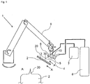
- FIG. 1 shows a device 1 for deburring a molded part 2, in particular in the form of a rubber molding 2, which is held in the present case by a suitable holding device, not shown.
- the molded part 2 has a ridge 20 which extends along the molded part 2 (see detail A) and is to be removed.
- the device 1 has a spray nozzle 5, which is in flow communication with a storage tank 8, in which a liquefied gas 4, in particular nitrogen, is stored.
- the spray nozzle 5 is e.g. via a carrier 10 with a guide 9, here in the form of a robot arm, coupled, which is adapted to three-dimensionally position the spray nozzle in the room.
- a carrier 10 with a guide 9, here in the form of a robot arm, coupled, which is adapted to three-dimensionally position the spray nozzle in the room.
- Other tours, including manual, are also possible.
- the guide 9 may cooperate with a control unit which controls the guide 9 so that the spray nozzle 5 is automatically moved along the ridge 20, the spray nozzle 5 preferably maintaining a substantially constant distance from the ridge.
- the device 1 furthermore has a CO 2 nozzle 6 for removing the ridge 20, which is flow-connected to a device 7 for storing and / or producing dry ice pellets 3.
- the device 7 is designed to eject the dry ice particles (eg dry ice pellets) 3 out of the CO 2 nozzle 6 by means of a carrier gas 30 and to shoot at the ridge 20.
- the CO 2 nozzle 6 is likewise coupled to the guide 9 (eg via the carrier 10), wherein the guide 9 is again designed to position the CO 2 nozzle 6 three-dimensionally in the space.
- the control or regulation unit regulates the guide 9 in such a way that the CO 2 nozzle 6 is automatically moved along the burr 20, wherein the CO 2 nozzle 6 likewise preferably maintains a substantially constant distance to the burr 20.
- the spray nozzle 5 is now first moved along the ridge 20, wherein this is sprayed with a liquefied gas 4, preferably liquid nitrogen 4 to embrittle the ridge 20.
- the CO 2 nozzle 6 can be guided in a separate process along the ridge 20 by means of the guide 9 in order to bombard the ridge 20 with dry ice particles or pellets 3.
- pellets 3 is fired and the ridge 20 thereby partially removed mechanically. In this case, therefore, the CO 2 nozzle 6 of the spray nozzle 5 moves behind.
- the pressure of the compressed air used (carrier gas 30) is 6 bar at about 0.15 kg / min.
- Dry ice pellets 3 (0.5 kg total) are shot on the ridge 20 embrittled with liquid nitrogen (1.3 kg / min).
- the liquid nitrogen has a pressure of 1.5 bar and is fed through a 1.5 m long hose of 6 mm nominal diameter to a spray nozzle, which is provided with a mouth hole of 2.5 mm diameter.
- the treatment time to remove the approximately 0.5 m long ridge 20 takes about 30-40 seconds without handling times.
- the two nozzles 5, 6 are moved at a speed of about 1 to 2 m / min.
- the parameters mentioned here are only an example, other process conditions and parameters are also possible.
Landscapes
- Engineering & Computer Science (AREA)
- Mechanical Engineering (AREA)
- Physics & Mathematics (AREA)
- Thermal Sciences (AREA)
- Processing And Handling Of Plastics And Other Materials For Molding In General (AREA)
- Carbon And Carbon Compounds (AREA)
- Cleaning In General (AREA)
Abstract
Die Erfindung betrifft ein Verfahren zum Entgraten eines Gummi-Formteiles (2), aufweisend die Schritte: Bereitstellen eines Gummi-Formteiles (2), das einen zu entfernenden Grat (20) aufweist, Kühlen des Grates durch beaufschlagen des Grates mit einem verflüssigtem Gas (4), und Beaufschlagen des Grates mit Trockeneispartikeln zur Entfernung des Grates. Weiterhin betrifft die Erfindung eine entsprechende Einrichtung (1) zum Entgraten von Gummi-Formteilen.
Description
- Die Erfindung betrifft ein Verfahren zum Entgraten von Formteilen, insbesondere Gummi-Formteilen. Unter einem Gummi-Formteil wird hierbei ein Formteil verstanden, das einen Grat aus einem Gummi aufweist, der insbesondere bei der Herstellung, z.B. Spritzgießen, aufgrund einer Teilung des Gießwerkzeuges bzw. der Gussform, entsteht. Weiterhin werden im Sinne der vorliegenden Erfindung unter dem Begriff Gummi neben Kautschuk, insbesondere vulkanisiertem Kautschuk, sowie synthetischem Kautschuk, sämtliche formfesten, elastisch verformbaren Kunststoffe verstanden, insbesondere Elastomere (z.B. Naturkautschuk oder Silikonkautschuk, siehe oben), thermoplastische Elastomere oder thermoplastische Kunststoffe, wie z.B. PPS.
- In der Regel wird bei Formteilen bzw. Gummi-Formteilen eine mechanische Entfernung von Graten vorgenommen. Oftmals wird die Entgratung dabei händisch durchgeführt, z.B. unter Zuhilfenahme von Abreißlaschen am Werkstück, Messern oder Schleifmitteln. Dieser Vorgang ist sehr zeit- und personalaufwändig.
- Der vorliegenden Erfindung liegt hiervon ausgehend die Aufgabe zugrunde ein Verfahren sowie eine Einrichtung zum Entgraten von Formteilen, insbesondere Gummi-Formteilen, anzugeben, das bzw. die die vorgenannten Nachteile mindert.
- Diese Aufgabe wird durch ein Verfahren mit den Merkmalen des Anspruchs 1 gelöst. Vorteilhafte Ausführungsformen des erfindungsgemäßen Verfahrens sind in den Unteransprüchen angegeben und werden nachfolgend beschrieben.
- Gemäß Anspruch 1 sind zumindest die folgenden Schritte vorgesehen:
- Bereitstellen eines Formteiles, das einen zu entfernenden Grat aufweist,
- Kühlen des Grates durch Beaufschlagen des Grates mit einem verflüssigtem Gas, und
- Beaufschlagen des Grates mit Trockeneispartikeln zur Entfernung des Grates.
- Bei dem Formteil kann es sich insbesondere um ein Formteil aus einem Gummi handeln (siehe oben) oder um ein Formteil aus einem thermoplastischem Kunststoff, insbesondere aus Polyphenylensulfid (PPS).
- Gemäß einer bevorzugten Ausführungsform des erfindungsgemäßen Verfahrens weisen die Trockeneispartikel, die z.B. als ein Produkt aus einem geraspeltem Trockeneisblock oder anderen größeren, geschabten oder vermahlenen Trockeneisprodukten erstellt werden können, einen Durchmesser im Bereich von 1 µm bis 5mm, vorzugsweise im Bereich von 0,05 mm bis 2 mm, auf.
- Gemäß einer Ausführungsform der Erfindung kann Trockeneisschnee als Trockeneispartikel verwendet werden. Die Partikelgröße bei Trockeneisschnee liegt vorzugsweise in einem Größenbereich zwischen 1 µm und 500 µm, insbesondere in einem Bereich von 30 µm bis 300 µm.
- Gemäß einer weiteren Ausführungsform der Erfindung können Trockeneispartikel in Form von Trockeneispellets verwendet werden. Die Partikelgröße bei Trockeneispellets liegt bevorzugt in einem Bereich von 0,3 mm bis 5 mm, insbesondere in einem Bereich von 1 mm bis 5 mm, insbesondere in einem Bereich von 1 mm bis 3 mm.
- Gemäß einer Ausführungsform der Erfindung kann z.B. auch geraspeltes Trockeneis verwendet werden, das von einem Trockeneisblock abgeraspelt wird, wobei hier insbesondere die Trockeneispartikel in einem Größenbereich von 0,1 mm bis 1 mm liegen.
- Weiterhin weisen die Trockeneispellets in Abhängigkeit des Pelletierers vorzugsweise eine Dichte im Bereich von 1,4 g/cm3 bis 1,7 g/cm3 auf, insbesondere ca. 1,56 g/cm3, sowie vorzugsweise eine Mohs-Härte im Bereich von ca. 1 bis 3 auf.
- Weiterhin werden die Trockeneispartikel (z.B. Trockeneispellets) bevorzugt mit einer Geschwindigkeit im Bereich von 80 bis 350 m/s auf den Grat geschossen. Hierbei werden die Trockeneispartikel vorzugsweise mit einem Trägergas, insbesondere Druckluft, auf den Grat geschossen.
- Durch ein Applizieren von kaltem, verflüssigtem Gas wird das Formteil idealerweise auf Temperaturen um den Glaspunkt des Materials des zu entgratenden Formteiles gebracht. Zumindest wird dadurch die Steifigkeit des Grates erhöht.
- Mittels der Trockeneispartikel wird der durch das Vorkühlen versprödete Grat des Formteiles mechanisch abgetragen. Hierbei spielt der Impuls der einzelnen Trockeneispartikel (z.B. Trockeneispellets) eine Rolle. Dieser wird bestimmt durch die Geschwindigkeit sowie die Größe und Dichte der Trockeneispartikel bzw. durch deren Masse.
- Zusätzlich wird durch die Verwendung der Trockeneispartikel beim Auftreffen auf den Grat weiterhin Wärme vom Grat in das jeweilige Partikel übertragen, so dass ein ausgeprägter Temperaturgradient und entsprechend hohe Scherkräfte im Grat entstehen, die das Abtragen des Grates unterstützen.
- Schließlich entsteht durch die Sublimation der Trockeneispartikel (z.B. Trockeneispellets) beim Auftreffen gasförmiges CO2, das im Vergleich zum festen Trockeneispartikel wesentlich mehr Volumen einnimmt. Diese explosionsartige Volumenzunahme erzeugt am Aufprallpunkt ebenfalls einen Impulseintrag in den Grat, der das Abtragen des Grates unterstützt.
- Ein Vorteil des erfindungsgemäßen Verfahrens liegt insbesondere darin, dass nicht nur der Grat des Formteiles entfernt wird, sondern gleichzeitig das Formteil durch die Beaufschlagung mit Trockeneispartikeln gereinigt wird.
- Gemäß einer weiteren bevorzugten Ausführungsform des erfindungsgemäßen Verfahrens handelt es sich bei dem verflüssigten Gas, das zum Vorkühlen bzw. Verspröden des Grates verwendet wird, um flüssigen Stickstoff.
- Gemäß einer weiteren bevorzugten Ausführungsform des erfindungsgemäßen Verfahrens ist vorgesehen, dass zum Beaufschlagen des Grates mit dem verflüssigtem Gas eine Sprühdüse, insbesondere automatisch, entlang des Grates bewegt wird, und das verflüssigte Gas mittels der Sprühdüse auf den Grat gesprüht wird.
- Gemäß einer weiteren bevorzugten Ausführungsform des erfindungsgemäßen Verfahrens ist vorgesehen, dass zum Beaufschlagen des Grates mit Trockeneispartikeln (z.B. Trockeneispellets) eine CO2-Düse entlang des Grates bewegt wird und die Trockeneispartikel mittels der CO2-Düse auf den Grat geschossen werden.
- Weiterhin wird das der Erfindung zugrunde liegende Problem durch eine Einrichtung zum Entgraten von Formteilen, insbesondere Gummi-Formteilen, mit den Merkmalen des Anspruchs 9 gelöst.
- Danach weist die erfindungsgemäße Entgratungseinrichtung ein Mittel auf, das dazu konfiguriert ist, den zu entfernenden Grat mit einem verflüssigten Gas zu beaufschlagen, insbesondere um den Grat vorzukühlen bzw. zu verspröden, sowie eine CO2-Düse, die dazu eingerichtet ist, Trockeneispartikel (z.B. Trockeneispellets) auf den Grat zu schießen.
- Das Mittel zum Beaufschlagen des Grates mit einem verflüssigtem Gas (insbesondere flüssiger Stickstoff, siehe oben) kann z.B. eine Sprühdüse aufweisen, die dazu konfiguriert ist, das verflüssigte Gas auf den zu entfernenden Grat zu sprühen.
- Weiterhin ist gemäß einer bevorzugten Ausführungsform der erfindungsgemäßen Einrichtung vorgesehen, dass die Einrichtung eine Vorrichtung aufweist, die zum Speichern und/oder Erzeugen der Trockeneispartikel ausgebildet ist, wobei die Vorrichtung vorzugsweise mit der CO2-Düse strömungsverbunden ist, so dass in der Vorrichtung gespeicherte und/oder erzeugte Trockeneispartikel über die CO2-Düse auf den Grat schießbar sind. Vorzugsweise ist die Vorrichtung dazu ausgebildet, die Trockeneispartikel mittels eines Trägergases, insbesondere Druckluft, zum Grat hin zu beschleunigen.
- Weiterhin ist bevorzugt vorgesehen, dass die Einrichtung eine Führung aufweist, die dazu ausgebildet ist, die CO2-Düse entlang des zu entfernenden Grates zu bewegen. Die Einrichtung ist vorzugsweise dazu konfiguriert, hierbei den Grat mit den Trockeneispartikeln zu beaufschlagen. Die CO2-Düse fährt dabei vorzugsweise den Grat in einem konstanten Abstand zum Grat ab.
- Die Führung kann ferner auch dazu ausgebildet sein, die besagte Sprühdüse entlang des zu entfernenden Grates zu bewegen. Die Einrichtung ist vorzugsweise dazu konfiguriert, hierbei den Grat mit dem verflüssigten Gas (z.B. Stickstoff) zu besprühen. Die Sprühdüse fährt dabei ebenfalls vorzugsweise den Grat in einem konstanten Abstand zum Grat ab.
- Es können natürlich auch separate Führungen für die Sprühdüse und die CO2-Düse vorgesehen werden.
- Weitere Merkmale und Vorteile der Erfindung sollen nachfolgend bei der Figurenbeschreibung von Ausführungsformen der Erfindung anhand der Figur erläutert werden. Es zeigt:
- Fig. 1
- eine schematische Darstellung einer erfindungsgemäßen Einrichtung bzw. eines erfindungsgemäßen Verfahrens zum Entgraten eines Formteils, insbesondere Gummi-Formteils.
-
Figur 1 zeigt eine Einrichtung 1 zum Entgraten eines Formteiles 2, insbesondere in Form eines Gummi-Formteils 2, das vorliegend durch eine geeignete nicht gezeigte Haltevorrichtung festgehalten wird. Das Formteil 2 weist einen Grat 20 auf, der sich entlang des Formteils 2 erstreckt (vgl. Detail A) und zu entfernen ist. - Hierzu weist die Einrichtung 1 eine Sprühdüse 5 auf, die mit einem Speichertank 8 in Strömungsverbindung steht, in dem ein verflüssigtes Gas 4, insbesondere Stickstoff, gespeichert ist.
- Die Sprühdüse 5 ist z.B. über einen Träger 10 mit einer Führung 9, hier in Form eines Roboterarms, gekoppelt, die dazu ausgebildet ist, die Sprühdüse 5 dreidimensional im Raum zu positionieren. Andere Führungen, auch händische, sind ebenfalls denkbar.
- Die Führung 9 kann mit einer Steuer- oder Regeleinheit zusammenwirken, die die Führung 9 so regelt, dass die Sprühdüse 5 automatisch entlang des Grates 20 bewegt wird, wobei die Sprühdüse 5 bevorzugt einen im Wesentlichen konstanten Abstand zum Grat einhält.
- Die Einrichtung 1 weist weiterhin zum Entfernen des Grates 20 eine CO2-Düse 6 auf, die mit einer Vorrichtung 7 zur Speicherung und/oder Erzeugung von Trockeneispellets 3 strömungsverbunden ist. Die Vorrichtung 7 ist dazu ausgebildet, die Trockeneispartikel (z.B. Trockeneispellets) 3 mittels eines Trägergases 30 aus der CO2-Düse 6 auszustoßen und auf den Grat 20 zu schießen.
- Die CO2-Düse 6 ist vorliegend ebenfalls (z.B. über den Träger 10) mit der Führung 9 gekoppelt, wobei die Führung 9 wiederum dazu ausgebildet ist, die CO2-Düse 6 dreidimensional im Raum zu positionieren. Die Steuer- oder Regeleinheit regelt hierbei die Führung 9 so, dass die CO2-Düse 6 automatisch entlang des Grates 20 bewegt wird, wobei die CO2-Düse 6 ebenfalls bevorzugt einen im Wesentlichen konstanten Abstand zum Grat 20 einhält.
- Zum Entfernen des Grates 20 des Formteiles 2, bei dem es sich zum Beispiel um eine Kfz-Dichtung handeln kann, wird nun zunächst die Sprühdüse 5 entlang des Grates 20 bewegt, wobei dieser mit einem verflüssigtem Gas 4, vorzugsweise flüssigem Stickstoff 4, besprüht wird, um den Grat 20 zu verspröden.
- Die CO2-Düse 6 kann in einem separaten Vorgang entlang des Grates 20 mittels der Führung 9 geführt werden, um den Grat 20 mit Trockeneispartikeln bzw. -pellets 3 zu beschießen. Es ist jedoch auch denkbar, die Sprühdüse 5 und die CO2-Düse 6 gemeinsam in einem einzigen Vorgang entlang des Grates 20 zu verfahren, wobei die Sprühdüse 5 zunächst verflüssigtes Gas 4 auf den jeweiligen Gratabschnitt versprüht und der solchermaßen versprödete Gratabschnitt sodann mit Trockeneispartikeln bzw. -pellets 3 beschossen wird und der Grat 20 dabei abschnittsweise mechanisch abgetragen wird. Hierbei bewegt sich also die CO2-Düse 6 der Sprühdüse 5 hinterher. Dies kann realisiert werden, indem die beiden Düsen 5, 6 z.B. starr an dem Träger 10 festgelegt werden und dieser mittels der Führung 9 entlang des Grates 20 bewegt wird, wobei die Sprühdüse 5 in der Bewegungsrichtung vor der CO2-Düse 6 angeordnet ist, die also der Sprühdüse 5 nachgeführt wird.
- Gemäß einem Beispiel des erfindungsgemäßen Verfahrens beträgt der Druck der verwendeten Druckluft (Trägergas 30) 6 bar bei etwa 0,15 kg/min. Die
- Trockeneispellets 3 (insgesamt 0,5 kg) werden auf den zuvor mit flüssigem Stickstoff (1,3 kg/min) versprödeten Grat 20 geschossen. Der flüssige Stickstoff weist dabei einen Druck von 1,5 bar auf und wird durch einen ca. 1,5 m langen Schlauch der Nennweite 6 mm an eine Sprühdüse zugeleitet, die mit einem Mundloch von 2,5 mm Durchmesser versehen ist. Die Behandlungsdauer zur Entfernung des etwa 0,5 m langen Grats 20 dauert hier in etwa 30-40 Sekunden ohne Handlingzeiten. Die beiden Düsen 5, 6 werden mit einer Geschwindigkeit von etwa 1 bis 2 m/min verfahren. Die hier genannten Parameter stellen lediglich ein Beispiel dar, andere Verfahrensbedingungen und -parameter sind ebenfalls möglich.
Bezugszeichenliste 1 Einrichtung 2 Formteil 3 Trockeneispartikel 4 Verflüssigtes Gas 5 Sprühdüse 6 CO2-Düse 7 Vorrichtung 8 Speichertank 9 Führung 10 Träger 20 Grat 30 Trägergas (z.B. Druckluft)
Claims (11)
- Verfahren zum Entgraten eines Formteiles (2), aufweisend die Schritte:- Bereitstellen eines Formteiles (2), das einen zu entfernenden Grat (20) aufweist,- Kühlen des Grates durch beaufschlagen des Grates (20) mit einem verflüssigtem Gas (4),- Beaufschlagen des Grates mit Trockeneispartikeln (3) zur Entfernung des Grates (20).
- Verfahren nach Anspruch 1, dadurch gekennzeichnet, dass die Trockeneispartikel (3) einen Durchmesser im Bereich von 1 µm bis 5mm aufweisen, insbesondere in einem Bereich von 0,05 mm bis 2 mm.
- Verfahren nach Anspruch 1 oder 2, dadurch gekennzeichnet, dass die Trockeneispartikel (3) eine Dichte im Bereich von 1,4 g/cm3 bis 1,7 g/cm3 aufweisen.
- Verfahren nach einem der vorhergehenden Ansprüche, dadurch gekennzeichnet, dass die Trockeneispartikel (3) mit einer Geschwindigkeit im Bereich von 80m/s bis 350m/s auf den Grat (20) geschossen werden.
- Verfahren nach einem der vorhergehenden Ansprüche, dadurch gekennzeichnet, dass die Trockeneispartikel (3) mit einem Trägergas (30), insbesondere Druckluft, auf den Grat (20) geschossen werden.
- Verfahren nach einem der vorhergehenden Ansprüche, dadurch gekennzeichnet, dass das verflüssigte Gas (4) flüssiger Stickstoff ist.
- Verfahren nach einem der vorhergehenden Ansprüche, dadurch gekennzeichnet, dass zum Beaufschlagen des Grates (20) mit dem verflüssigtem Gas (4) eine Sprühdüse (5), insbesondere automatisch, entlang des Grates (20) bewegt wird, und das verflüssigte Gas mittels der Sprühdüse (5) auf den Grat (20) gesprüht wird.
- Verfahren nach einem der vorhergehenden Ansprüche, dadurch gekennzeichnet, dass zum Beaufschlagen des Grates (20) mit Trockeneispartikeln (3) eine CO2-Düse (6) entlang des Grates (20) bewegt wird, und die Trockeneispartikel (3) über die CO2-Düse (6) auf den Grat (20) geschossen werden.
- Einrichtung (1) zum Entgraten von Formteilen (2), mit- einem Mittel (5), das dazu konfiguriert ist, den zu entfernenden Grat (20) mit einem verflüssigten Gas (4) zu beaufschlagen, und- einer CO2-Düse (6), die dazu konfiguriert ist, Trockeneispartikel (3) auf den Grat (20) zu schießen.
- Einrichtung nach Anspruch 9, dadurch gekennzeichnet, dass die Einrichtung (1) eine Vorrichtung (7) zum Speichern und/oder Erzeugen der Trockeneispartikel (3) aufweist, wobei die Vorrichtung (7) mit der CO2-Düse (6) verbunden ist, so dass in der Vorrichtung (7) gespeicherte und/oder erzeugte Trockeneispartikel (3) über die CO2-Düse (5) auf den Grat (20) schießbar sind, und wobei insbesondere die Vorrichtung (7) dazu ausgebildet ist, die Trockeneispartikel (3) mittels eines Trägergases (30), insbesondere Druckluft, auf den Grat (20) zu schießen.
- Einrichtung nach Anspruch 9 oder 10, dadurch gekennzeichnet, dass die Einrichtung (1) eine Führung (9) aufweist, die dazu ausgebildet ist, die CO2-Düse (6) entlang des zu entfernenden Grates (20) zu bewegen.
Applications Claiming Priority (1)
| Application Number | Priority Date | Filing Date | Title |
|---|---|---|---|
| DE102015003942.3A DE102015003942A1 (de) | 2015-03-26 | 2015-03-26 | Entgraten von Formteilen, insbesondere Gummi-Formteile |
Publications (1)
| Publication Number | Publication Date |
|---|---|
| EP3072638A1 true EP3072638A1 (de) | 2016-09-28 |
Family
ID=55661039
Family Applications (1)
| Application Number | Title | Priority Date | Filing Date |
|---|---|---|---|
| EP16000695.3A Withdrawn EP3072638A1 (de) | 2015-03-26 | 2016-03-23 | Entgraten von formteilen, insbesondere gummi-formteile |
Country Status (3)
| Country | Link |
|---|---|
| US (1) | US20160279836A1 (de) |
| EP (1) | EP3072638A1 (de) |
| DE (1) | DE102015003942A1 (de) |
Cited By (4)
| Publication number | Priority date | Publication date | Assignee | Title |
|---|---|---|---|---|
| CN106985076A (zh) * | 2017-03-31 | 2017-07-28 | 广东天机工业智能系统有限公司 | 自动除毛刺系统 |
| DE102017009498A1 (de) | 2017-10-12 | 2019-04-18 | Petra Lauer | Verfahren zum Kaltentgraten von Formteilen |
| CN112372368A (zh) * | 2020-10-29 | 2021-02-19 | 惠州市特创电子科技有限公司 | 铣床铣切降温装置 |
| CN113878092A (zh) * | 2021-08-04 | 2022-01-04 | 肇庆本田金属有限公司 | 一种气道砂芯自动去毛刺及自动搬送的方法及装置 |
Families Citing this family (5)
| Publication number | Priority date | Publication date | Assignee | Title |
|---|---|---|---|---|
| US10207391B2 (en) * | 2016-04-29 | 2019-02-19 | Robin A. Rhodes | Dry ice parts finishing system |
| CN108705454A (zh) * | 2018-06-29 | 2018-10-26 | 东莞市固德自动化科技有限公司 | 一种自动干冰去毛刺机 |
| TW202126408A (zh) | 2020-01-02 | 2021-07-16 | 財團法人工業技術研究院 | 毛邊清除裝置 |
| DE102021105761A1 (de) * | 2021-03-10 | 2022-09-15 | Bayerische Motoren Werke Aktiengesellschaft | Verfahren zum Trennen oder Wiedergewinnen von Materialien von Elektroden, Verfahren zur Herstellung einer Elektrode sowie Elektrode |
| CN116728665B (zh) * | 2023-08-11 | 2023-10-27 | 佛山市鑫永金属制品有限公司 | 一种导轨缓冲成型件生产设备 |
Citations (6)
| Publication number | Priority date | Publication date | Assignee | Title |
|---|---|---|---|---|
| US3702519A (en) * | 1971-07-12 | 1972-11-14 | Chemotronics International Inc | Method for the removal of unwanted portions of an article by spraying with high velocity dry ice particles |
| WO1997006923A1 (en) * | 1995-08-11 | 1997-02-27 | Crycle Cryogenic C.V. | Method and apparatus for cutting, abrading, and drilling with sublimable particles and vaporous liquids |
| WO2003086668A1 (en) * | 2002-04-05 | 2003-10-23 | Boc, Inc. | Fluid assisted cryogenic cleaning |
| US20050172984A1 (en) * | 2004-02-11 | 2005-08-11 | Applied Materials, Inc. | Cleaning of chamber components |
| DE102005012377A1 (de) * | 2005-03-17 | 2006-09-21 | Linde Ag | Verfahren zum Entgraten von Formteilen |
| DE102007009090A1 (de) * | 2007-02-24 | 2008-08-28 | Mycon Gmbh | Vorrichtung und Verfahren zur Entgratung von Kunststoffteilen mittels Kaltstrahlverfahrens mit mechanischer Unterstützung durch ein Spezialwerkzeug |
Family Cites Families (6)
| Publication number | Priority date | Publication date | Assignee | Title |
|---|---|---|---|---|
| US4038786A (en) * | 1974-09-27 | 1977-08-02 | Lockheed Aircraft Corporation | Sandblasting with pellets of material capable of sublimation |
| JP2750895B2 (ja) * | 1989-05-22 | 1998-05-13 | 株式会社ニッサンキ | ステアリングホイールの加工装置 |
| US5931721A (en) * | 1994-11-07 | 1999-08-03 | Sumitomo Heavy Industries, Ltd. | Aerosol surface processing |
| US7316363B2 (en) * | 2004-09-03 | 2008-01-08 | Nitrocision Llc | System and method for delivering cryogenic fluid |
| US7293570B2 (en) * | 2004-12-13 | 2007-11-13 | Cool Clean Technologies, Inc. | Carbon dioxide snow apparatus |
| US8820199B2 (en) * | 2007-09-21 | 2014-09-02 | Air Products And Chemicals, Inc. | Apparatus and method for machining polymers with controlled croygenic cooling |
-
2015
- 2015-03-26 DE DE102015003942.3A patent/DE102015003942A1/de not_active Withdrawn
-
2016
- 2016-03-23 US US15/077,994 patent/US20160279836A1/en not_active Abandoned
- 2016-03-23 EP EP16000695.3A patent/EP3072638A1/de not_active Withdrawn
Patent Citations (6)
| Publication number | Priority date | Publication date | Assignee | Title |
|---|---|---|---|---|
| US3702519A (en) * | 1971-07-12 | 1972-11-14 | Chemotronics International Inc | Method for the removal of unwanted portions of an article by spraying with high velocity dry ice particles |
| WO1997006923A1 (en) * | 1995-08-11 | 1997-02-27 | Crycle Cryogenic C.V. | Method and apparatus for cutting, abrading, and drilling with sublimable particles and vaporous liquids |
| WO2003086668A1 (en) * | 2002-04-05 | 2003-10-23 | Boc, Inc. | Fluid assisted cryogenic cleaning |
| US20050172984A1 (en) * | 2004-02-11 | 2005-08-11 | Applied Materials, Inc. | Cleaning of chamber components |
| DE102005012377A1 (de) * | 2005-03-17 | 2006-09-21 | Linde Ag | Verfahren zum Entgraten von Formteilen |
| DE102007009090A1 (de) * | 2007-02-24 | 2008-08-28 | Mycon Gmbh | Vorrichtung und Verfahren zur Entgratung von Kunststoffteilen mittels Kaltstrahlverfahrens mit mechanischer Unterstützung durch ein Spezialwerkzeug |
Cited By (5)
| Publication number | Priority date | Publication date | Assignee | Title |
|---|---|---|---|---|
| CN106985076A (zh) * | 2017-03-31 | 2017-07-28 | 广东天机工业智能系统有限公司 | 自动除毛刺系统 |
| CN106985076B (zh) * | 2017-03-31 | 2020-02-11 | 广东天机工业智能系统有限公司 | 自动除毛刺系统 |
| DE102017009498A1 (de) | 2017-10-12 | 2019-04-18 | Petra Lauer | Verfahren zum Kaltentgraten von Formteilen |
| CN112372368A (zh) * | 2020-10-29 | 2021-02-19 | 惠州市特创电子科技有限公司 | 铣床铣切降温装置 |
| CN113878092A (zh) * | 2021-08-04 | 2022-01-04 | 肇庆本田金属有限公司 | 一种气道砂芯自动去毛刺及自动搬送的方法及装置 |
Also Published As
| Publication number | Publication date |
|---|---|
| US20160279836A1 (en) | 2016-09-29 |
| DE102015003942A1 (de) | 2016-09-29 |
Similar Documents
| Publication | Publication Date | Title |
|---|---|---|
| DE102015003942A1 (de) | Entgraten von Formteilen, insbesondere Gummi-Formteile | |
| EP2389282B1 (de) | Werkzeug und verfahren zur herstellung von mehrschicht-kunststoffformteilen | |
| DE2418658A1 (de) | Spritzgiessform | |
| WO2008067962A2 (de) | Reparatur und/oder konturänderung einer formoberfläche eines formwerkzeugs | |
| WO2018050926A1 (de) | Verfahren und vorrichtung für das recycling von thermoplastischem faserverbundmaterial | |
| DE102010032965A1 (de) | Streckblasmaschine mit integriertem Kompressor | |
| DE102010049025A1 (de) | Formträger- und Reckschlittenventil | |
| CH423215A (de) | Verfahren und Vorrichtung zur kontinuierlichen Herstellung von Formteilen oder Profilsträngen aus thermoplastischen Kunststoffen mit Zellstruktur | |
| DE102007009090A1 (de) | Vorrichtung und Verfahren zur Entgratung von Kunststoffteilen mittels Kaltstrahlverfahrens mit mechanischer Unterstützung durch ein Spezialwerkzeug | |
| EP1889707A2 (de) | Verfahren und Vorrichtung zum Entfernen von Kunststoffmaterialüberschuss von einem Kunststoffbauteil | |
| DE102016011808B4 (de) | Verfahren zum Behandeln einer Oberfläche mit einem Strahlmittel | |
| EP3359337B1 (de) | Verfahren zum reinigen von klebeflächen mithilfe von festen kohlenstoffdioxid | |
| DE3913649A1 (de) | Verfahren und anlage zum herstellen metallischer pulver aus einer metallschmelze durch gasverduesen | |
| EP3345745A1 (de) | Fertigungsanlage und verfahren zur herstellung eines bauteils | |
| DE102008044026B4 (de) | Verfahren zur Herstellung eines Verbundbauteils und dadurch hergestelltes Verbundbauteil | |
| EP1882531A2 (de) | Verfahren und Anordnung zum Reinigen von mit Lüftungskanälen versehenen Lüftungskörpern aus Kunststoff | |
| DE19813347A1 (de) | Hochabriebfester Niederhalter für Faltdächer | |
| DE102019007439A1 (de) | Vorrichtung zum Erzeugen und Transportieren von Trockeneispellets | |
| DE102023110700A1 (de) | Plastifiziereinheit und/oder Einspritzeinheit für eine Formgebungsmaschine | |
| EP1793974A1 (de) | Vorrichtung zum auswerfen von pet-vorformlingen | |
| DE102011055153A1 (de) | Blasmaschine mit automatischer Prozesswinkeloptimierung | |
| EP2492077B1 (de) | Verfahren und Vorrichtung zur Erhöhung der Polarität der Oberfläche eines EPP-Formteiles | |
| DE10309674B4 (de) | Konturgenaues Bedampfen von mit einem textilen Gewebe überzogenen Kunststoffformteilen zur Verbesserung der textilen Oberfläche | |
| DE102015014212A1 (de) | Erzeugung mikrozellulär geschäumter Spritzguss-Bauteile aus mit einem Treibmittel imprägniertem Kunststoff-Granulat | |
| DE102007037267A1 (de) | Verfahren und Vorrichtung zur Herstellung eines Schallschutz-Verbundbauteils |
Legal Events
| Date | Code | Title | Description |
|---|---|---|---|
| PUAI | Public reference made under article 153(3) epc to a published international application that has entered the european phase |
Free format text: ORIGINAL CODE: 0009012 |
|
| AK | Designated contracting states |
Kind code of ref document: A1 Designated state(s): AL AT BE BG CH CY CZ DE DK EE ES FI FR GB GR HR HU IE IS IT LI LT LU LV MC MK MT NL NO PL PT RO RS SE SI SK SM TR |
|
| AX | Request for extension of the european patent |
Extension state: BA ME |
|
| STAA | Information on the status of an ep patent application or granted ep patent |
Free format text: STATUS: THE APPLICATION IS DEEMED TO BE WITHDRAWN |
|
| 18D | Application deemed to be withdrawn |
Effective date: 20170329 |