EP3072001B1 - In einem band gebündelte markierte vieladrige glasfasern - Google Patents
In einem band gebündelte markierte vieladrige glasfasern Download PDFInfo
- Publication number
- EP3072001B1 EP3072001B1 EP14870646.8A EP14870646A EP3072001B1 EP 3072001 B1 EP3072001 B1 EP 3072001B1 EP 14870646 A EP14870646 A EP 14870646A EP 3072001 B1 EP3072001 B1 EP 3072001B1
- Authority
- EP
- European Patent Office
- Prior art keywords
- colored portion
- core elements
- marked
- multicore
- fiber
- Prior art date
- Legal status (The legal status is an assumption and is not a legal conclusion. Google has not performed a legal analysis and makes no representation as to the accuracy of the status listed.)
- Not-in-force
Links
Images


Classifications
-
- G—PHYSICS
- G02—OPTICS
- G02B—OPTICAL ELEMENTS, SYSTEMS OR APPARATUS
- G02B6/00—Light guides; Structural details of arrangements comprising light guides and other optical elements, e.g. couplings
- G02B6/44—Mechanical structures for providing tensile strength and external protection for fibres, e.g. optical transmission cables
- G02B6/4479—Manufacturing methods of optical cables
- G02B6/4482—Code or colour marking
-
- B—PERFORMING OPERATIONS; TRANSPORTING
- B29—WORKING OF PLASTICS; WORKING OF SUBSTANCES IN A PLASTIC STATE IN GENERAL
- B29C—SHAPING OR JOINING OF PLASTICS; SHAPING OF MATERIAL IN A PLASTIC STATE, NOT OTHERWISE PROVIDED FOR; AFTER-TREATMENT OF THE SHAPED PRODUCTS, e.g. REPAIRING
- B29C48/00—Extrusion moulding, i.e. expressing the moulding material through a die or nozzle which imparts the desired form; Apparatus therefor
- B29C48/15—Extrusion moulding, i.e. expressing the moulding material through a die or nozzle which imparts the desired form; Apparatus therefor incorporating preformed parts or layers, e.g. extrusion moulding around inserts
-
- B—PERFORMING OPERATIONS; TRANSPORTING
- B29—WORKING OF PLASTICS; WORKING OF SUBSTANCES IN A PLASTIC STATE IN GENERAL
- B29D—PRODUCING PARTICULAR ARTICLES FROM PLASTICS OR FROM SUBSTANCES IN A PLASTIC STATE
- B29D11/00—Producing optical elements, e.g. lenses or prisms
- B29D11/00663—Production of light guides
- B29D11/00721—Production of light guides involving preforms for the manufacture of light guides
-
- C—CHEMISTRY; METALLURGY
- C03—GLASS; MINERAL OR SLAG WOOL
- C03C—CHEMICAL COMPOSITION OF GLASSES, GLAZES OR VITREOUS ENAMELS; SURFACE TREATMENT OF GLASS; SURFACE TREATMENT OF FIBRES OR FILAMENTS MADE FROM GLASS, MINERALS OR SLAGS; JOINING GLASS TO GLASS OR OTHER MATERIALS
- C03C25/00—Surface treatment of fibres or filaments made from glass, minerals or slags
- C03C25/10—Coating
- C03C25/104—Coating to obtain optical fibres
- C03C25/1065—Multiple coatings
-
- C—CHEMISTRY; METALLURGY
- C03—GLASS; MINERAL OR SLAG WOOL
- C03C—CHEMICAL COMPOSITION OF GLASSES, GLAZES OR VITREOUS ENAMELS; SURFACE TREATMENT OF GLASS; SURFACE TREATMENT OF FIBRES OR FILAMENTS MADE FROM GLASS, MINERALS OR SLAGS; JOINING GLASS TO GLASS OR OTHER MATERIALS
- C03C25/00—Surface treatment of fibres or filaments made from glass, minerals or slags
- C03C25/10—Coating
- C03C25/12—General methods of coating; Devices therefor
-
- G—PHYSICS
- G02—OPTICS
- G02B—OPTICAL ELEMENTS, SYSTEMS OR APPARATUS
- G02B6/00—Light guides; Structural details of arrangements comprising light guides and other optical elements, e.g. couplings
- G02B6/02—Optical fibres with cladding with or without a coating
- G02B6/02042—Multicore optical fibres
-
- G—PHYSICS
- G02—OPTICS
- G02B—OPTICAL ELEMENTS, SYSTEMS OR APPARATUS
- G02B6/00—Light guides; Structural details of arrangements comprising light guides and other optical elements, e.g. couplings
- G02B6/02—Optical fibres with cladding with or without a coating
- G02B6/02395—Glass optical fibre with a protective coating, e.g. two layer polymer coating deposited directly on a silica cladding surface during fibre manufacture
-
- G—PHYSICS
- G02—OPTICS
- G02B—OPTICAL ELEMENTS, SYSTEMS OR APPARATUS
- G02B6/00—Light guides; Structural details of arrangements comprising light guides and other optical elements, e.g. couplings
- G02B6/44—Mechanical structures for providing tensile strength and external protection for fibres, e.g. optical transmission cables
- G02B6/4401—Optical cables
- G02B6/4403—Optical cables with ribbon structure
-
- G—PHYSICS
- G02—OPTICS
- G02B—OPTICAL ELEMENTS, SYSTEMS OR APPARATUS
- G02B6/00—Light guides; Structural details of arrangements comprising light guides and other optical elements, e.g. couplings
- G02B6/44—Mechanical structures for providing tensile strength and external protection for fibres, e.g. optical transmission cables
- G02B6/4401—Optical cables
- G02B6/4429—Means specially adapted for strengthening or protecting the cables
- G02B6/443—Protective covering
-
- G—PHYSICS
- G02—OPTICS
- G02B—OPTICAL ELEMENTS, SYSTEMS OR APPARATUS
- G02B6/00—Light guides; Structural details of arrangements comprising light guides and other optical elements, e.g. couplings
- G02B6/44—Mechanical structures for providing tensile strength and external protection for fibres, e.g. optical transmission cables
- G02B6/4479—Manufacturing methods of optical cables
- G02B6/448—Ribbon cables
-
- G—PHYSICS
- G02—OPTICS
- G02B—OPTICAL ELEMENTS, SYSTEMS OR APPARATUS
- G02B6/00—Light guides; Structural details of arrangements comprising light guides and other optical elements, e.g. couplings
- G02B6/44—Mechanical structures for providing tensile strength and external protection for fibres, e.g. optical transmission cables
- G02B6/4479—Manufacturing methods of optical cables
- G02B6/4486—Protective covering
-
- H—ELECTRICITY
- H04—ELECTRIC COMMUNICATION TECHNIQUE
- H04B—TRANSMISSION
- H04B10/00—Transmission systems employing electromagnetic waves other than radio-waves, e.g. infrared, visible or ultraviolet light, or employing corpuscular radiation, e.g. quantum communication
- H04B10/40—Transceivers
-
- B—PERFORMING OPERATIONS; TRANSPORTING
- B29—WORKING OF PLASTICS; WORKING OF SUBSTANCES IN A PLASTIC STATE IN GENERAL
- B29L—INDEXING SCHEME ASSOCIATED WITH SUBCLASS B29C, RELATING TO PARTICULAR ARTICLES
- B29L2011/00—Optical elements, e.g. lenses, prisms
- B29L2011/0075—Light guides, optical cables
-
- G—PHYSICS
- G01—MEASURING; TESTING
- G01M—TESTING STATIC OR DYNAMIC BALANCE OF MACHINES OR STRUCTURES; TESTING OF STRUCTURES OR APPARATUS, NOT OTHERWISE PROVIDED FOR
- G01M11/00—Testing of optical apparatus; Testing structures by optical methods not otherwise provided for
- G01M11/30—Testing of optical devices, constituted by fibre optics or optical waveguides
- G01M11/37—Testing of optical devices, constituted by fibre optics or optical waveguides in which light is projected perpendicularly to the axis of the fibre or waveguide for monitoring a section thereof
-
- G—PHYSICS
- G02—OPTICS
- G02B—OPTICAL ELEMENTS, SYSTEMS OR APPARATUS
- G02B6/00—Light guides; Structural details of arrangements comprising light guides and other optical elements, e.g. couplings
- G02B6/24—Coupling light guides
- G02B6/36—Mechanical coupling means
- G02B6/38—Mechanical coupling means having fibre to fibre mating means
- G02B6/3807—Dismountable connectors, i.e. comprising plugs
- G02B6/381—Dismountable connectors, i.e. comprising plugs of the ferrule type, e.g. fibre ends embedded in ferrules, connecting a pair of fibres
- G02B6/3826—Dismountable connectors, i.e. comprising plugs of the ferrule type, e.g. fibre ends embedded in ferrules, connecting a pair of fibres characterised by form or shape
- G02B6/3831—Dismountable connectors, i.e. comprising plugs of the ferrule type, e.g. fibre ends embedded in ferrules, connecting a pair of fibres characterised by form or shape comprising a keying element on the plug or adapter, e.g. to forbid wrong connection
-
- G—PHYSICS
- G02—OPTICS
- G02B—OPTICAL ELEMENTS, SYSTEMS OR APPARATUS
- G02B6/00—Light guides; Structural details of arrangements comprising light guides and other optical elements, e.g. couplings
- G02B6/24—Coupling light guides
- G02B6/36—Mechanical coupling means
- G02B6/38—Mechanical coupling means having fibre to fibre mating means
- G02B6/3807—Dismountable connectors, i.e. comprising plugs
- G02B6/3833—Details of mounting fibres in ferrules; Assembly methods; Manufacture
- G02B6/3851—Ferrules having keying or coding means
-
- G—PHYSICS
- G02—OPTICS
- G02B—OPTICAL ELEMENTS, SYSTEMS OR APPARATUS
- G02B6/00—Light guides; Structural details of arrangements comprising light guides and other optical elements, e.g. couplings
- G02B6/24—Coupling light guides
- G02B6/36—Mechanical coupling means
- G02B6/38—Mechanical coupling means having fibre to fibre mating means
- G02B6/3807—Dismountable connectors, i.e. comprising plugs
- G02B6/3873—Connectors using guide surfaces for aligning ferrule ends, e.g. tubes, sleeves, V-grooves, rods, pins, balls
- G02B6/3885—Multicore or multichannel optical connectors, i.e. one single ferrule containing more than one fibre, e.g. ribbon type
-
- G—PHYSICS
- G02—OPTICS
- G02B—OPTICAL ELEMENTS, SYSTEMS OR APPARATUS
- G02B6/00—Light guides; Structural details of arrangements comprising light guides and other optical elements, e.g. couplings
- G02B6/24—Coupling light guides
- G02B6/42—Coupling light guides with opto-electronic elements
- G02B6/4201—Packages, e.g. shape, construction, internal or external details
- G02B6/4246—Bidirectionally operating package structures
-
- G—PHYSICS
- G02—OPTICS
- G02B—OPTICAL ELEMENTS, SYSTEMS OR APPARATUS
- G02B6/00—Light guides; Structural details of arrangements comprising light guides and other optical elements, e.g. couplings
- G02B6/24—Coupling light guides
- G02B6/42—Coupling light guides with opto-electronic elements
- G02B6/4201—Packages, e.g. shape, construction, internal or external details
- G02B6/4249—Packages, e.g. shape, construction, internal or external details comprising arrays of active devices and fibres
-
- G—PHYSICS
- G02—OPTICS
- G02B—OPTICAL ELEMENTS, SYSTEMS OR APPARATUS
- G02B6/00—Light guides; Structural details of arrangements comprising light guides and other optical elements, e.g. couplings
- G02B6/24—Coupling light guides
- G02B6/42—Coupling light guides with opto-electronic elements
- G02B6/4292—Coupling light guides with opto-electronic elements the light guide being disconnectable from the opto-electronic element, e.g. mutually self aligning arrangements
Definitions
- the present disclosure generally relates to optical fibers and, more specifically, to multicore optical fibers.
- Optical fiber is the leading alternative to traditional materials used for data signal communication such as copper wiring.
- Optical fiber is now widely utilized in a variety of electronic devices and systems to facilitate the high-speed communication of voice, video, and data signals at high bandwidths.
- One solution to increase the speed of optical interconnects is to increase the fiber density of the optical interconnects.
- increasing the number of individual fibers in an optical interconnect increases the overall size and cost of the optical interconnect.
- MCFs multicore optical fibers
- the core elements are designed for, for example, the transmission and receiving of data, and can be arranged as transmit and receive (Tx/Rx) pairs.
- Tx/Rx transmit and receive
- Such MCFs may be used in data networks to enable high speed Tx/Rx transmission of data between system components such as transceivers, processors, servers, and storage devices.
- connectors are attached to the MCFs.
- Tx/Rx optical transport and connections to be manufactured it is important for the operators to know the orientation of the optical fibers when the connectors are terminated to the MCFs.
- JP 2011 158768 A and US20130322835 A1 disclose marked multicore optical fibers.
- FR 2 746 930 A1 discloses a marked multicore optical fiber, comprising at least one reference section adjacent to the coating layer, wherein the reference section comprises at least one colored portion, and the coating layer comprises a colored material, and wherein the colored portion comprises a relatively distinct color compared to the colored material of the coating layer color.
- FR 2 613 981 A1 and EP 0 562 259 A1 show additional prior art.
- the invention provides a grouping according to claim 1.
- An exemplary method comprises the steps of translating an uncoated multicore optical fiber between an energy source and a detector, directing a beam of the energy source so that it at least partially impinges upon the multicore optical fiber causing an image to be detected by the detector, and the detector sending output to a controller, the controller determining the orientation of at least some of the core elements in the multicore optical fiber, and controlling a spinning or traction device and thereby adjusting the orientation of the multicore optical fiber in relation to its optical core elements and a coating die, passing the multicore optical fiber through the coating die and applying a material to the multicore optical fiber thus defining a coating portion, and applying a material in the form of a colored portion being visually distinct from the coating portion.
- the step of detecting the image of at least some of the core elements can include at least partial absorption of the energy by at least one dopant which is respectively part of the optical core elements, and the dopant can be, for example, a germanium dopant.
- the dopant can be, for example, a germanium dopant.
- Other dopants can be used in accordance with the disclosure which will potentially result in alternative absorption and transmittance characteristics.
- the step of energy absorption can cause fluorescence and the step of determining the orientation of at least some of the core elements can involve imaging of the fluorescence.
- the step of energy absorption can cause index of refraction differences and the step of detection of the image can thus be based upon interferometry.
- determining the orientation of at least some of the core elements in the multicore optical fiber can include programming at least one characteristic absorption wavelength band of the dopant and cladding in an imaging system.
- applying a material to the coating portion can include a colored portion visually distinct from the coating portion including one of co-extruding the colored portion and of applying an ink to the outer surface of the coating portion, and combinations thereof.
- applying the colored portion can comprise one of forming the colored portion with one or more stripes, dashes, rings, or a series of rings and stripes thereon, and combinations thereof.
- the manufacturing method can comprise translating at least two multicore optical fibers, aligning the colored portions respectively of the multicore optical fibers, coating the multicore optical fibers with a matrix material so they are contained in the matrix, curing the matrix material, and optionally applying a reference section to the matrix.
- translating the multicore optical fibers can include drawing an uncoated multicore optical fiber from a draw tower or supplying a multicore fiber with a colored portion from a reel.
- the step of coating the multicore optical fiber can occur after cooling of the multicore optical fiber.
- determining the core element orientation can occur prior to the coating application step and can include controlling the traction device prior to application of the coating.
- the steps of applying the colored portion can be one of various embodiments for example: directly applying the colored portion to the glass after a cooling step but prior to the coating application step, directly applying the colored portion to the coating after the coating step but before a curing step of the coating, directly applying the colored portion to the coating after a curing step of the coating, and combinations thereof.
- a multicore optical fiber generally comprises a common outer cladding formed from silica-based glass and having a cladding index of refraction.
- At least one optical core element for example, a single mode core element or a multimode core element, or a combination of such elements, are disposed in the common outer cladding.
- the core element(s) are formed from, for example, silica-based glass with a higher index of refraction than the cladding.
- a center-to-center spacing between adjacent core elements is for example, greater than or equal to aboul 25 ⁇ m or less.
- multimode refers to a core element which supports the propagation of multiple modes of light at the specified wavelength(s) of, for example, 850 nm to 1550 nm.
- Multicore fibers are made by exemplary processes disclosed in Corning Incorporated United States Patent Nos. 6,539,151 and 6,154,594 . The multicore fibers of the embodiments of the disclosure shown, for example in FIGs.
- optical core elements 14,15,16,17 are exemplary and include generally round outer shapes and round optical core elements 14,15,16,17.
- the optical core elements can be other shapes such as rectangular, polygonal, flat, or elliptical as shown in US Patent Publication No. US 20130177273 A1 .
- forms of multicore fibers other than round, such as rectangular, hexagonal, partly flat and partly rounded forms, and multicore fibers made with a series of curved surfaces such as are as disclosed in US Publication US20130322835 A1 .
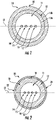
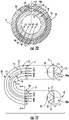
- FIG. 1 depicts a MCF component 10 with optical core elements, for example, core elements 14, 15, 16, and 17 contained within a common outer cladding 11 that is covered by a coating system 12 comprising a primary coating 12a and a secondary coating 12b defining a coating system 12.
- Coating system 12 comprises at least one first reference section which comprises, a UV light curable resin which is formed of, for example, a first colored material 18.
- Core elements 14,15,16,17 are generally aligned along their respective centers along a line "L1".
- the optical core elements 14,15,16,17 can be arranged in a row as shown, for example, in FIGs. 1, 2 , and 10 .
- the common outer cladding 11 comprises a silica-based glass having a cladding index of refraction.
- optical core elements 14 and 15 are designed to communicate data, for example, to transmit data (Tx), and core elements 16 and 17 are designed to communicate data, for example, to receive data (Rx) ( FIG. 11 ).
- a fiber optic connector can be attached to MCF component 10 and would connect to, for example, an opto/electronic transceiver device ( FIGs. 11 and 12 ). The connector is keyed to align core elements 14 and 15 with the device, such as Vertical Cavity Surface Emitting Laser transmitters for Tx purposes, and core elements 16 and 17 are to be aligned with optical/electronic receiver devices for Rx purposes ( FIG. 13 ).
- MCF components 10 can have two or more single mode core elements, two or more multimode core elements, or a combination of single mode and multimode core elements disposed in common outer cladding 11.
- MCF component 10 includes at least one coating layer, for example, a layer 21,22 formed of, for example, at least one ink color material as a part of coating system 12 defining a marked MCF 20.
- the coating layer includes a coating portion 21 comprising an optical fiber color such as blue or red, and at least one adjacent colored portion 22 comprising a relatively distinct color such as black or white.
- colored portion 22 is disposed in alignment with exemplary line L1, for example, and colored portion 22 can take the form of a continuous or intermittent stripe or line of constant or varying width.
- colored portion 22 is disposed in relation to the first reference section, for example, colored portion 18.
- Colored portion 22 is adjacent to coating portion 21 in the sense that colored portion 22 is co-extruded with coating portion 21, as is further described below.
- the color distinction between portions 20 and 21 is observable, during a connector attachment process, by an operator with or without specialized equipment such as optical magnification or illumination equipment.
- At least one colored portion 22 can be applied, in an adjacent sense, integrally with the thickness of coating 21, or applied to a surface of the coating layer with one or more applicators 36 ( FIGs. 3-4 ) for example printing devices, for example, ink jet style printers.
- An applicator can form, for example, a continuous or intermittent line with dots and dashes and combinations thereof.
- the applicator can be located between a coating die and a UV-light curing device as further described below ( FIG. 4 ).
- colored portion 22 can be aligned with an axis of the core elements as shown with reference to exemplary line L2 ( FIG. 10 ) above core elements 14,15,16,17, for example, at an angle of about 90 degrees relative to line L1.
- the location and composition of colored portion 22, and additional colored portions 22, can be added as desired, and can be disposed at various locations relative to, for example, the center of marked MCF 20 to facilitate the operator's requirements as needed.
- the reference sections can be placed at various radial locations, for example, a marked MCF 20 can have at least one colored portion 18 aligned with line L2 ( FIG. 10 ) and at least one colored portion 22 aligned with line L1 ( FIG.
- the angular precision of colored portion 22 relative to exemplary lines L1 and L2 can be adjusted depending on the requirements for the application in which it is used. In general, for the purposes of orienting marked MCF 20 with a connector or to identify the top of a fiber in production ( FIGs. 11-13 ), in an exemplary embodiment, the angular accuracy can be on the order of, for example, +/- 1 degree of arc.
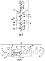
- FIG. 3 depicts an exemplary glass optical fiber manufacturing process 70 such that the first reference section, for example, colored portion 18 is disposed on the optical fiber during the fiber drawing process forming a MCF component 10.
- a draw tower for making multicore optical fiber includes a furnace 72 for heating a glass preform 71 having a multicore fiber construction, a diameter monitor 73, and a cooling system 74 for cooling an uncoated multicore fiber 75 from a high furnace temperature to a lower temperature to allow application of, for example, UV curable acrylate coatings to protect the glass fiber from damage.
- coating system 12 is applied by a coating system 77a, and is cured by exposure to appropriate energy, for example, respective UV light sources.
- Coating system 77a comprises two stages, a first stage applying primary coating 12a followed by curing, and a second stage applying secondary coating 12b followed by curing, thereby defining coating system 12.
- both coatings comprise a UV curable acrylate mixture of monomers, oligomers, photoinitiators, and additives, and the mixtures are cured at respective curing stations.
- One such exemplary curing station 78a is shown in FIG. 3 .
- exemplary diameters for MCF component 10 include: cladding 11 at 125 ⁇ m, primary coating 12a at 190 ⁇ m, and secondary coating 12b at 245 ⁇ m which is the diameter of the coated multicore fiber such as MCF component 10.
- the manufacturing line can include equipment applying a translucent or transparent coating portion 21 with a coating system 77b which is cured by a single stage UV light station 78b.
- the coated multicore optical fiber is pulled by tractor 80 in the general direction of arrow 81.
- An optical fiber spin device 79 can be located below the coating curing unit 78b. The fiber spin device has rotational elements engaging the fiber to allow twisting of the optical fiber back and forth.
- Detection of core elements 14,15,16,17 is accomplished by monitoring their positions prior to applying the acrylate coatings to the multicore optical fiber. More specifically, prior to application of the coatings, an imaging and control system 76,76a,76b provides an energy beam source 76 emitting an energy beam of a wavelength "W". The beam impinges on uncoated multicore fiber 75 and the beam is imaged by imaging device 76a, the output thereof is sent to controller 76b which outputs a control signal to fiber spin device 79 and an applicator 36 as shown and described with reference to FIG. 4 . Controller 76b is operative to control applicator 36 for control of application of the colored portion 18. Fiber rotational alignment is accomplished by fiber spin device 79 as described above which, rather than imparting a random twist, is driven by controller 76b to control angular alignment of the multicore optical fiber.
- Colored portion 18 can be applied in a variety of locations to allow for variations in desired shapes and radial positions relative to the core elements.
- colored portion 18, as described with reference to applicator 36 ( FIG. 4 ) can be applied in various stations along the manufacturing line 70 ( FIG. 3 ) and still be controlled by controller 76b.
- applicator 36 can apply the material comprising the first reference material, for example, colored portion 18, onto a wet secondary coating 12b at position 82a between coating system 77a and curing station 78a, onto a cured secondary coating 12b at position 82b between curing station 78a and coating system 77b, or by co-extrusion with secondary coating 12b.
- Completion of the foregoing addition of colored portion 18 produces a MCF component 10 ( FIG 1 ).
- Manufacturing considerations play a role in electing whether to run MCF component 10 to stock on a reel and adding a coating 21 and colored portion 22 with a separate process ( FIG. 4 ), or to optionally add coating 21 and with a second reference for example a colored portion 22 with respect to the additional thickness process described above ( FIG. 3 ).
- colored portion 22 can be added to MCF component 10 by locating applicator 36 so that it applies the reference section onto a wet secondary coating comprising coating 21 at position 82c ( FIG. 3 ) between coating system 77b and curing station 78b, or onto a cured secondary coating comprising coating 21 at position 82d after curing station 78b.
- Combinations of the foregoing can be implemented as well, for example, where multiple applicators 36 are used in selected positions 82a-82d respectively.
- a first method involves the detection of the partial or complete absence of light by detector 76a.
- light at wavelength(s) W impinges onto uncoated fiber 75 and can pass or be absorbed by the germanium dopant which is part of the core elements.
- the measurement by detector 76a can be done by optical imaging of a wavelength(s) of light that is highly absorbed by the germanium, causing a shadow or absence of such wavelength(s).
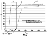
- germanium doped glass has a strong absorption of light at wavelengths shorter than approximately 270 nm as shown by curve C1.
- strong absorption in silica glass SiO2 starts at significantly shorter wavelengths as shown by curve C2 (reference for example Applied Optics Vol. 23, No. 24, 15 December 1984 ), in other words, the silica absorption becomes appreciable at wavelengths shorter than approximately 180 nm.
- Zone S generally disposed between wavelength W1 of about 180 nm and wavelength W2 of about 270 nm, represents an exemplary spectral region for detecting Germania doped optical core elements disposed in a transparent cladding of uncoated multicore fiber 75.
- shadowing measurements by the imaging control system 76,76a,76b of the shadowing effects of the germania-doped cores 14,15,16,17 embedded within the silica cladding 11 are in generally in zone S at wavelengths W1, W2 of between about 180 nm and 270 nm respectively.
- the transmittance, as a function of wavelength band W1,W2, and as associated with zone S, is in a range of about 80-90%.
- other transmissivities can be attained by adjusting the wavelength(s) used, for example, comprising a zone R ( FIG. 7 ), having a wavelength of about W1 and a relatively higher wavelength of about 300 nm resulting in a transmittance range of about 70-80% through uncoated multicore fiber 75.
- a minimum wavelength W1 of about 180 nm can be employed with embodiments of the present disclosure.
- a number of commercially available light sources 76 are available in the exemplary wavelength range W1,W2, including lasers at 266, 257 and 244 nm.
- Non-laser light sources are also available, for example, which operate (at least partially) in the W1,W2 region include Deuterium bulb (190-400 nm), Xenon (220-visible), and LED 240 nm, and available from Ocean Optics Inc.
- the germanium-doped cores can be caused to fluoresce and then be detected by imaging system 76,76a,76b.
- imaging system 76,76a,76b This is possible as germanium-doped optical fibers and preforms can fluoresce at wavelength(s) W near 420 nm when excited by UV radiation at a wavelength below 350 nm, as discussed in " Ultraviolet-excited fluorescence in optical fibers and preforms".
- light source 76, detector 76a, and controller 76b, operating as an imaging system are to be adjusted to detect and react to the light absorption or fluorescent characteristics of the dopant associated with the optical core elements, as in this exemplary embodiment, the germanium dopant.
- light can be transmitted laterally through the uncoated fiber 75 and the index of refraction differences can be detected, again, through interferometry or commercially available imaging techniques.
- a characteristic absorption band for example, between wavelengths W1,W2 is to be programmed into and detected by the imaging system 76,76a,76b through uncoated multicore fiber 75.
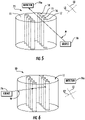
- FIGs. 5 and 6 illustrate exemplary core element measurement orientations at a position after cooling station 74 ( FIG. 3 ).
- FIG. 5 depicts light source 76 directing an energy beam such as light beam "W" comprising one or more detection wavelength(s) based on the known or characteristic absorption band, for example zones S and R, with wavelength boundaries W1,W2 based on the relevant dopant of core elements 14,15,16,17, for example, germanium, and cladding 11 ( FIG. 7 ).
- Beam W transits cladding 11 between, for example, one or more rows of core elements 14,15,16,17 and shadowing of the detection wavelength(s) is detected by detector 76a ( FIG. 5 ).
- FIG. 6 depicts source 76 directing beam W toward outer cladding 11, but the detection wavelength(s) W largely impinges upon, and is partially or wholly absorbed by, the dopant of core elements 14,15,16,17.
- the detection wavelength(s) W may not be detected by detector 76a, or is otherwise at a minimum amplitude in the imaging system, as rotation of the uncoated fiber 75 varies, indicating that beam W is generally perpendicular to the at least one row of core elements, as is the case when the beam is essentially parallel to line L2 ( FIG. 10 ).
- Controller 76b contains a programmable device such as a computer or microprocessor, and it will be programmed to, as one output control signal, adjust fiber spin device 79 to control the orientation of the multifiber fiber core with respect to the core element position as imaged, for example, as by rotation of the multifiber core to allow maximum detection wavelength values to impinge on detector 76a.
- a programmable device such as a computer or microprocessor
- controller 76b will control fiber spin device 79 so that the core elements 14,15,16,17 will be essentially parallel to beam W and line L2 whereby colored portion 18 will be applied by applicator 36 to the top of the multicore fiber ( FIGs. 1, 2 , and 10 ).
- applicator 36 can be integrated into coloring die 77a, being a co-extrusion die, thereby co-extruding colored portion 18 with secondary coating 12b.
- Colored portion 18 can be coextruded comprising a stripe of UV curable ink material(s) of essentially the same thickness as coating system 12.
- applicator 36 can be mounted to be moved to different axial or radial locations relative to MCF component 10. Multiple applicators 36 can be used so that the multicore fiber can have a series of stripes, dashes or a series of rings and stripes on its outer surface of various or similar colors and combinations thereof.
- MCF component 10 may be made on draw line 70, reeled, and sent to inventory in the factory.
- FIG. 4 depicts an exemplary manufacturing process including a marking line 30.
- Marking line 30 is moving product generally in the direction of arrow "A".
- Marking line 30 contains a scanning camera system 31,32 detecting energy such as visible wavelength light which light is reflecting from the surface of MCF component 10. Camera system 31,32 thus detects colored portion 18 on the surface of MCF component 10. This information is transmitted to controller 34 for tracking the orientation of the core elements in MCF component 10.
- Exemplary controller, scanning cameras, and applicators are disclosed in US Patent Nos. 6,293,081 , 5,904,037 , and 5,729,966 of Corning Cable Systems .
- a caterpuller is a traction device with moving belts, having potentially variable speeds, arranged to frictionally engage an elongate article such as a fiber, cable, or cable components, and to draw or force the article in a generally rectilinear direction, for example, drawing an article off of a reel and propelling it toward an extrusion die.
- a caterpuller 33 contains upper and lower drive belts 33a and 33b respectively.
- Upper drive belt 33a has a rotational drive that moves MCF component 10 through the process
- lower drive belt 33b has a lateral drive which causes MCF component 10 to roll or twist between belts 33a,33b.
- Controller 34 adjusts the dispositions of caterpuller 33 based on inputs from detectors 31,32 such that the orientation of MCF component 10, based on detection of colored portion 18, is established and maintained in relation to core elements 14,15,16,17.
- MCF component 10 passes through a coloring die 35 that applies a UV curable layer defining coating portion 21, for example, which can be translucent, transparent, or of a first color such as white, red, or orange.
- At least one applicator 36 applies a second material to coating portion 21 in the form of a stripe, dashed line, or combination thereof defining colored portion 22, which is to be visually distinct from coating portion 21, and thus portion 22 can be a second color for example, black or blue.
- the coating portion 21 and colored portion 22 are cured by a UV-light source 37 to produce a marked MCF 20.
- Colored portion 22 defines a reference section for an operator's connector termination purposes, and, in this embodiment, the colored portion comprises a color that is, to an operator's observation, visually distinct from coating portion 21.
- marked MCF 20 are constrained relative to an optical fiber ribbon matrix ( FIG. 8 ) and a reference section is added comprising a groove, dent, or colored portion, such as colored portion 52 ( FIG. 8 ), which colored portion is aligned with a respective colored portion 22.
- a marked MCF 20 is constrained relative to a tight buffered cable jacket ( FIG. 10 ).
- an optional reference section can be added comprising a groove, dent or colored portion, such as and colored portion 23a ( FIG. 10 ), which colored portion is generally aligned with a respective colored portion 22.
- groupings of MCFs 20 are formed according to the claimed invention in the form of ribbon cable 50 ( FIG. 8 ) with marked MCFs 20 aligned within the ribbon. Marked MCFs 20 are bonded together with a matrix material 51, for example, a UV-light curable acrylate matrix. Colored portions 22 of each marked MCF 20 in optical fiber ribbon 50 can be generally aligned, for example, toward the same direction or side of the ribbon, such as toward the side of colored portion 52.
- the colored portions 22 can be aligned in different directions within the same optical ribbon, for example, MCFs 20 that are to be utilized by an operator as transmit data (Tx) can be aligned toward one side of the optical fiber ribbon, and MCFs 20 that are to be utilized by an operator to receive data (Rx) can be aligned toward a different direction.
- Alignment variations for example, can be set according to an angle ⁇ of about 45 from line L1 or L2 ( FIG. 8 ).
- Optical fiber ribbon 50 can be connectorized with multi-fiber connectors, for example, commercially available push on MPO or MTP ® fiber optic connectors.
- optical core elements can be arranged in a column format so that the MCF 20 are aligned with line L2 rather than line L1. An entire column of fiber will enable each fiber to be connected in the same orientation to transceivers on both the proximal and distal sides of the fiber ribbon.
- a twist of the ribbon will arrange the optical fiber cores, and for a multicore fiber having columns and rows of optical core elements, a shuffle with a left to right mirror image transposition arrangement of the cores would maintain the optical core elements on the correct orientation at both ends.
- FIG. 9 shows an exemplary optical fiber ribbon manufacturing line 60 moving product generally in direction "B" with marked MCFs 20 having colored portions 22 generally aligned. This means the colored portions are within 0-45 degrees of each other relative to the top center of the optical fiber as angle ⁇ illustrates in FIG. 8 .
- Process 60 has a series of fiber pay-off assemblies 61, for example, four to six assemblies 61, each supplying the aligned MCFs 20 into a coating die 66 which coats the marked MCFs 20 with matrix material 51.
- the number of fiber pay-off assemblies 61 is determined by the number of marked MCFs 20 desired for the optical ribbon 50 being manufactured. For example, a 4-fiber ribbon would have four pay-offs 61, and a 12-fiber ribbon would have twelve pay-offs 61.
- Pay-off assemblies 61 each comprise a reel assembly that allows its marked MCF 20 to pay off under controlled tension.
- Scanning cameras 64 are positioned to observe marked MCFs 20 to determine the orientation of the colored section 22 and provide a feedback control signal 65 to a drive motor 63 that rotates the respective reel assemblies 62 to control the orientation of MCFs 20.
- Matrix material 51 is in turn cured by a UV-light source 67 to produce optical fiber ribbon 50 with MCFs 20 having colored portions 22, which as described above, can be aligned according to the same or different angles.
- one or more marked MCF 20s can be constrained relative to a further layer of material such as a tight buffered cable jacket ( FIG. 10 ).
- an optional reference section can be added comprising a groove, dent, or colored portion, such as colored portion 23 a ( FIG. 10 ).
- scanning cameras can be used to detect colored portion 22 and then an extrusion die would extrude a tight buffered cable jacket onto coating portion 21, and another applicator 36 would apply the colored portion 23a.
- a proximal transceiver may have two transmit ports T1 and T2 and two receive ports R1 and R2. As viewed from the end of the transceiver, the ports would be arranged from left to right for example as T1, T2, R2, R1 ( FIG. 11 ).
- the outer two ports T1,R1 define a two-way communication channel 1 and the inner two ports T2,R2 define a two-way communication channel 2.
- Marked MCF 20 with colored portion 22 positioned up in the proximate transceiver would place core element 14 in communication with a transmitter T1, core element 15 in communication with transmitter T2, core element 16 in communication with receiver R2, and core element 17 in communication with receiver R1.
- the distal end of the multicore fiber would be placed into the distal transceiver in the same orientation with colored portion 22 oriented in an up position which would align core element 14 with receiver R1 and core element 17 with transmitter T1.
- the signal from transmitter T1 in the proximal transceiver will go to receiver R1 in the distal transceiver via core element 14.
- the signal from transmitter T1 in the distal transceiver will go to receiver R1 in the proximal transceiver over core element 17.
- the connector is assembled with colored portion 22 toward the top of the connector on both ends of the fiber, which will ensure that the cores 14,15,16,17 are aligned with the correct ports.
- reference line L2 is on a line of symmetry of marked MCF 20 that does not intersect any core elements, and optical core elements on the left hand side of line L2 ( FIG. 10 ) of marked MCF 20, for example core elements 14 and 15, have essentially a corresponding mirror image of core elements on the right side of line L2, for example, core elements 16 and 17.
- core elements 14 and 15 when the cable is in a loop of a 180 degree bend, as in a factory termination procedure, and as shown in FIG. 11 , core elements 14 and 15 define a pair of corresponding core elements and core elements 16 and 17 also define a pair of corresponding core elements.
- Core elements 14 and 15 are above line L2 and are disposed for optical communication with transmitters at the proximal end of the cable "P".
- core elements 14,15 are below line L2 for optical communication with receivers.
- core elements 16 and 17 are disposed at distal end D of marked MCF 20 above line L2 for optical communication with transmitters, and they are below line L2 for optical communication with receivers at the proximal end P of marked MCF 20.
- each core element 14,15,16,17 is to be connected at each end P and D, for example, to respective optical connectors, which are in turn associated with transceivers.
- the same transceiver design can be used on both ends, and the operator is to make sure the at least one colored portion 22 is positioned indicating alignment of the optical elements with the optical connector.
- colored portion 22 aligned with line L2 is at the top at both ends of the fiber/cable and is to be aligned with a connector for termination.
- Marked MCF 20 can interface with connector portions 25a,25b having respective angled polished ends 20a,20b as shown in FIG. 12 .
- Angular polished ends 20a,20b are oriented relative to cores 14,15,16,17 in a way that the polished ends can be arranged for connection on either end P,D with devices such as connectors, a mid-span connector 26, or transceivers.
- Line L2 is generally in the plane of the angularly polished surfaces 20a,20b, and line L1 is aligned with the optical core elements 14,15,16,17 and transits the angled polish plane but is generally transverse to the plane of the angled polish.
- Line L1 will form an angle relative to the angularly polished surface generally equal to the angle of the polish.
- the polish angle being, for example, an angle of about 8-9 degrees relative to line L1.
- Both ends P,D of marked MCF 20 can be prepared by the process of flock polishing.
- An exemplary flock polishing technique is described in U.S. Patent No. 6,106,368 of Corning Cables Systems .
- the optical connector includes a key 27 ( FIG. 13 ).
- colored portion 22 is aligned with key 27 along the same axis
- line L2 is generally aligned with key 27 as well.
- the disposition of key 27 is at an angle ⁇ relative to the optical core elements and line L1 ( FIG.
- Colored portion 18 can be aligned with colored portion 22 ( FIG. 10 ) or radially offset therefrom ( FIG. 2 ). Both ends of marked MCF 20 can be attached to a respective fiber optic connecter, as described above, defining a jumper cable assembly, or only one end can be attached to a connector thereby defining a pigtail cable assembly. As described above, colored portions 18 and 22 can be in the non-aligned positions with respect to each other ( FIG. 2 ) and during connectorization.
- colored portion 22 will be on a first side of the proximal termination side, and on the opposing side of the distal termination side, and with colored portion 18 on the top in ( FIG. 12 ), and coating 21 should be transparent or translucent so that colored portion 18 is observable therethrough.
Landscapes
- Physics & Mathematics (AREA)
- Engineering & Computer Science (AREA)
- General Physics & Mathematics (AREA)
- Optics & Photonics (AREA)
- Life Sciences & Earth Sciences (AREA)
- Chemical & Material Sciences (AREA)
- Manufacturing & Machinery (AREA)
- Mechanical Engineering (AREA)
- Organic Chemistry (AREA)
- Materials Engineering (AREA)
- General Life Sciences & Earth Sciences (AREA)
- Chemical Kinetics & Catalysis (AREA)
- General Chemical & Material Sciences (AREA)
- Geochemistry & Mineralogy (AREA)
- Ophthalmology & Optometry (AREA)
- Health & Medical Sciences (AREA)
- Computer Networks & Wireless Communication (AREA)
- Electromagnetism (AREA)
- Signal Processing (AREA)
- Optical Fibers, Optical Fiber Cores, And Optical Fiber Bundles (AREA)
- Optical Couplings Of Light Guides (AREA)
- Surface Treatment Of Glass Fibres Or Filaments (AREA)
- Mechanical Coupling Of Light Guides (AREA)
Claims (5)
- Gruppierung von markierten mehrkernigen Lichtleiterfasern (20), wobei die markierten mehrkernigen Lichtleiterfasern (20) aufweisen:(a) optische Kernelemente (14, 15, 16, 17), wobei die optischen Kernelemente (14, 15, 16, 17) eine Anordnung von zumindest zwei optischen Kernelementen definieren, die innerhalb einer gemeinsamen äußeren Ummantelung (11) enthalten sind, wobei die gemeinsame äußere Ummantelung (11) zumindest teilweise von einer Beschichtungsschicht (21) umgeben ist, die außerhalb der Ummantelung (11) angeordnet ist, und wobei die optischen Kernelemente (14, 15, 16, 17) allgemein entlang einer ersten Referenzlinie (L1) ausgerichtet sind und in der Lage sind, Daten zu übertragen; und(b) die mehrkernige Lichtleiterfaser (20) zumindest ein Referenzsegment benachbart zu der Beschichtungsschicht (21) aufweist, wobei das Referenzsegment zumindest einen gefärbten Abschnitt (22) aufweist, und die Beschichtungsschicht (21) ein gefärbtes Material aufweist, und wobei der gefärbte Abschnitt (22) eine relativ unterscheidbare Farbe aufweist, verglichen mit dem gefärbten Material der Beschichtungsschicht (21), wobei der gefärbte Abschnitt (22) eine coextrudierte Schicht benachbart zu der Beschichtungsschicht (21) aufweist, wobei die coextrudierte Schicht mit der Beschichtungsschicht (21) coextrudiert ist,wobei die Gruppierung in Form eines Lichtleiterfaserbands (50) vorliegt, wobei die markierten mehrkernigen Lichtleiterfasern (20) innerhalb des Bands (50) entlang der ersten Referenzlinie (L1) oder entlang einer Linie mit einem Winkel von 90 Grad zu der ersten Referenzlinie (L1) ausgerichtet sind und mit einem Matrixmaterial (51) aneinander gebondet sind, wobei das Band (50), welches ein Referenzsegment aufweist, eine Nut, Einbuchtung oder einen gefärbten Abschnitt (52) aufweist, und wobei das Referenzsegment mit einem jeweiligen gefärbten Abschnitt (22) ausgerichtet ist.
- Gruppierung nach Anspruch 1, wobei der gefärbte Abschnitt (22) ausgewählt ist aus einem durch UV-Licht härtbaren Harzmaterial und einem Tintenmaterial und Kombinationen davon.
- Gruppierung nach einem der Ansprüche 1 oder 2, wobei der gefärbte Abschnitt (22) sich entlang der mehrkernigen Lichtleiterfaser erstreckt und eine Form von einer von einer kontinuierlichen Linie, einer intermittierenden Linie und einer Kombination davon aufweist.
- Gruppierung nach einem der Ansprüche 1 bis 3, wobei der gefärbte Abschnitt (22) allgemein in Ausrichtung mit der Referenzlinie (L1) angeordnet ist.
- Gruppierung nach einem der Ansprüche 1 bis 3, wobei der gefärbte Abschnitt (22) allgemein oberhalb der Referenzlinie (L1) angeordnet ist.
Applications Claiming Priority (3)
| Application Number | Priority Date | Filing Date | Title |
|---|---|---|---|
| US201361907755P | 2013-11-22 | 2013-11-22 | |
| US14/136,434 US9696513B2 (en) | 2013-11-22 | 2013-12-20 | Multicore optical fibers and methods of manufacturing the same |
| PCT/US2014/063989 WO2015126470A2 (en) | 2013-11-22 | 2014-11-05 | Multicore optical fibers and methods of manufacturing the same |
Publications (2)
| Publication Number | Publication Date |
|---|---|
| EP3072001A2 EP3072001A2 (de) | 2016-09-28 |
| EP3072001B1 true EP3072001B1 (de) | 2022-07-20 |
Family
ID=53385922
Family Applications (1)
| Application Number | Title | Priority Date | Filing Date |
|---|---|---|---|
| EP14870646.8A Not-in-force EP3072001B1 (de) | 2013-11-22 | 2014-11-05 | In einem band gebündelte markierte vieladrige glasfasern |
Country Status (4)
| Country | Link |
|---|---|
| US (2) | US9696513B2 (de) |
| EP (1) | EP3072001B1 (de) |
| CN (1) | CN105899981A (de) |
| WO (1) | WO2015126470A2 (de) |
Families Citing this family (35)
| Publication number | Priority date | Publication date | Assignee | Title |
|---|---|---|---|---|
| JP6097890B2 (ja) * | 2014-08-29 | 2017-03-15 | 古河電気工業株式会社 | 多心コネクタ |
| US9958604B2 (en) * | 2014-09-24 | 2018-05-01 | Furukawa Electric Co., Ltd. | Optical fiber, and optical-fiber production method |
| US9835812B2 (en) * | 2015-08-04 | 2017-12-05 | Corning Incorporated | Multi-optical fiber aggregate |
| US10001597B2 (en) | 2015-09-22 | 2018-06-19 | Corning Incorporated | Multicore optical fibers and interconnection methods for the same |
| WO2017077050A1 (en) * | 2015-11-06 | 2017-05-11 | CommScope Connectivity Belgium BVBA | Optical fiber alignment mechanisms |
| AU2017264006B2 (en) * | 2016-05-12 | 2021-10-28 | Sumitomo Electric Industries, Ltd. | Multicore optical fiber, fiber bragg grating, and method for manufacturing fiber bragg grating |
| US10903905B2 (en) | 2016-09-12 | 2021-01-26 | Hewlett Packard Enterprise Development Lp | Optical transceiver modules |
| CN107346046A (zh) * | 2017-06-30 | 2017-11-14 | 南京吉隆光纤通信股份有限公司 | 具有侧面识别标记的非圆对称光纤 |
| US10677983B2 (en) * | 2017-07-31 | 2020-06-09 | Ofs Fitel, Llc | Optically uniform fiber, methods of making, and methods of inspecting |
| CN107656342A (zh) * | 2017-08-25 | 2018-02-02 | 江苏中天科技股份有限公司 | 一种新型防鼠咬光缆及其制作方法 |
| WO2021015970A1 (en) * | 2019-07-23 | 2021-01-28 | Corning Incorporated | Apparatus and methods for accurate high-speed marking of optical fibers |
| WO2021044902A1 (ja) * | 2019-09-02 | 2021-03-11 | Kddi株式会社 | 通信装置及び通信システム |
| US10859772B1 (en) * | 2019-09-23 | 2020-12-08 | Ofs Fitel, Llc | Routing of multicore optical fibers in data networks |
| WO2021070241A1 (ja) * | 2019-10-08 | 2021-04-15 | 日本電信電話株式会社 | コア位置把握方法、接続方法、及び接続装置 |
| WO2021151045A1 (en) * | 2020-01-23 | 2021-07-29 | 4S-Silversword Software And Services, Llc | Multicore fiber optic gyro |
| US11916598B2 (en) * | 2020-04-13 | 2024-02-27 | Avicenatech Corp. | Parallel optical communication channels using microLEDs |
| CN112068320B (zh) * | 2020-09-14 | 2022-11-18 | 哈尔滨工程大学 | 一种基于多芯光纤的光致微马达 |
| JP2022075176A (ja) * | 2020-11-06 | 2022-05-18 | 株式会社フジクラ | 光ファイバの製造方法 |
| CN116710820A (zh) * | 2020-12-25 | 2023-09-05 | 住友电气工业株式会社 | 光纤带、光纤连接部件以及光纤连接部件的制造方法 |
| US20250164733A1 (en) * | 2021-09-13 | 2025-05-22 | Fujikura Ltd. | Optical fiber cable, optical fiber ribbon, method of installing optical fiber cable, and optical transmission system |
| US11988886B1 (en) * | 2022-03-31 | 2024-05-21 | Amazon Technologies, Inc. | Ribbon fanout for multicore fiber connectivity |
| US12321013B1 (en) | 2022-03-31 | 2025-06-03 | Amazon Technologies, Inc. | Multicore fiber connectivity |
| EP4556976A4 (de) * | 2022-07-13 | 2025-10-29 | Sumitomo Electric Industries | Verfahren und vorrichtung zur herstellung eines faseroptischen bandkabels |
| US12181716B2 (en) | 2022-08-17 | 2024-12-31 | Corning Research & Development Corporation | Multicore optical fiber connector adapters |
| JP7474388B1 (ja) * | 2022-08-29 | 2024-04-24 | Swcc株式会社 | 光ファイバテープ心線の製造方法 |
| EP4641276A1 (de) * | 2022-12-22 | 2025-10-29 | Fujikura Ltd. | Optisches faserband, mit verbinder ausgestattetes optisches faserband, glasfaserkabel und glasfaser |
| JPWO2024166574A1 (de) * | 2023-02-09 | 2024-08-15 | ||
| US20240319461A1 (en) * | 2023-03-22 | 2024-09-26 | Ofs Fitel, Llc | Optical fiber ribbon print spacing for reduced transmission loss |
| JPWO2024224985A1 (de) * | 2023-04-24 | 2024-10-31 | ||
| WO2025023306A1 (ja) * | 2023-07-25 | 2025-01-30 | 住友電気工業株式会社 | 光ファイバテープ心線および光ファイバテープ心線の製造方法 |
| CN117420630A (zh) * | 2023-10-19 | 2024-01-19 | 长飞光纤光缆股份有限公司 | 带折射率标记的空芯微结构光纤、其制备及检测方法 |
| CN120195823A (zh) * | 2023-12-22 | 2025-06-24 | 长飞光纤光缆股份有限公司 | 一种空芯微结构光纤带及其制备方法 |
| WO2025173711A1 (ja) * | 2024-02-13 | 2025-08-21 | 住友電気工業株式会社 | 光ファイバ、光ファイバの製造方法、テープファイバ、および、テープファイバの製造方法 |
| WO2025249165A1 (ja) * | 2024-05-31 | 2025-12-04 | 住友電気工業株式会社 | テープファイバおよび光配線 |
| WO2025263438A1 (ja) * | 2024-06-17 | 2025-12-26 | 住友電気工業株式会社 | 光ファイバ、光ファイバ平型素線、光ファイバテープ心線、および、光ファイバテープ心線の製造方法 |
Citations (5)
| Publication number | Priority date | Publication date | Assignee | Title |
|---|---|---|---|---|
| JPS5813505U (ja) * | 1981-07-17 | 1983-01-27 | 日本電信電話株式会社 | マルチコア光フアイバ |
| FR2613981A1 (fr) * | 1987-04-15 | 1988-10-21 | Swisscab E A Schoen Sa | Procede et tete d'extrusion d'elements profiles en matiere synthetique ayant des bandes colorees |
| EP0562259A1 (de) * | 1992-03-26 | 1993-09-29 | KABEL RHEYDT Aktiengesellschaft | Optische Faser mit zusätzlicher Farbmarkierung |
| FR2746930A1 (fr) * | 1996-03-29 | 1997-10-03 | Marer Rene Le | Fibre optique multicoeur permettant le reperage des coeurs |
| US20110129190A1 (en) * | 2009-12-02 | 2011-06-02 | Ofs Fitel, Llc | Techniques for Manipulating Crosstalk in Multicore Fibers |
Family Cites Families (17)
| Publication number | Priority date | Publication date | Assignee | Title |
|---|---|---|---|---|
| JP2610347B2 (ja) * | 1989-09-22 | 1997-05-14 | 住友電気工業株式会社 | テープ状光ファイバ心線 |
| US5729966A (en) | 1996-06-28 | 1998-03-24 | Siecor Corporation | Method of marking optical fiber lay direction reversal points on cable jackets |
| US6293081B1 (en) | 1997-06-12 | 2001-09-25 | Siecor Operations, Llc | Fiber optic cable marking process and a sensor device use therewith |
| US5904037A (en) | 1997-06-12 | 1999-05-18 | Siecor Corporation | Fiber optic cable reversal point marking process and a marking device for use therewith |
| US6154594A (en) | 1998-07-15 | 2000-11-28 | Corning Incorporated | Multicore glass optical fiber and methods of manufacturing such fibers |
| US6106368A (en) | 1998-11-18 | 2000-08-22 | Siecor Operations, Llc | Polishing method for preferentially etching a ferrule and ferrule assembly |
| US6539151B2 (en) | 2000-08-21 | 2003-03-25 | Corning, Incorporated | Method for making separable multiple core optical fibers, the resulting fiber structures, and uses thereof |
| US7900481B2 (en) | 2006-05-19 | 2011-03-08 | Corning Incorporated | Method of making an optical fiber |
| JP5413222B2 (ja) | 2010-02-02 | 2014-02-12 | 住友電気工業株式会社 | マルチコア光ファイバ及びマルチコア光ファイバの接続方法 |
| JP5267481B2 (ja) | 2010-02-18 | 2013-08-21 | 住友電気工業株式会社 | マルチコア光ファイバ |
| WO2012009307A1 (en) | 2010-07-12 | 2012-01-19 | Corning Incorporated | Cylindrical vector beam generation from a multicore optical fiber |
| JP5782502B2 (ja) | 2011-03-04 | 2015-09-24 | 株式会社フジクラ | マルチコアファイバ、及び、それを用いたマルチコアファイバの接続方法 |
| JP6082523B2 (ja) | 2011-08-01 | 2017-02-15 | 古河電気工業株式会社 | マルチコアファイバの接続方法、マルチコアファイバ、マルチコアファイバの製造方法 |
| US20130044978A1 (en) | 2011-08-20 | 2013-02-21 | Peter DeDobbelaere | Method And System For A Multi-Core Fiber Connector |
| JP5842556B2 (ja) * | 2011-11-11 | 2016-01-13 | 住友電気工業株式会社 | 双方向光通信方法およびマルチコア光ファイバ |
| JP5867076B2 (ja) * | 2011-12-28 | 2016-02-24 | 住友電気工業株式会社 | マルチコア光ファイバ |
| US9057815B2 (en) | 2012-05-31 | 2015-06-16 | Corning Cable Systems Llc | Angular alignment of optical fibers for fiber optic ribbon cables, and related methods |
-
2013
- 2013-12-20 US US14/136,434 patent/US9696513B2/en active Active
-
2014
- 2014-11-05 CN CN201480072427.0A patent/CN105899981A/zh active Pending
- 2014-11-05 EP EP14870646.8A patent/EP3072001B1/de not_active Not-in-force
- 2014-11-05 WO PCT/US2014/063989 patent/WO2015126470A2/en not_active Ceased
-
2017
- 2017-06-06 US US15/615,332 patent/US10156693B2/en active Active
Patent Citations (5)
| Publication number | Priority date | Publication date | Assignee | Title |
|---|---|---|---|---|
| JPS5813505U (ja) * | 1981-07-17 | 1983-01-27 | 日本電信電話株式会社 | マルチコア光フアイバ |
| FR2613981A1 (fr) * | 1987-04-15 | 1988-10-21 | Swisscab E A Schoen Sa | Procede et tete d'extrusion d'elements profiles en matiere synthetique ayant des bandes colorees |
| EP0562259A1 (de) * | 1992-03-26 | 1993-09-29 | KABEL RHEYDT Aktiengesellschaft | Optische Faser mit zusätzlicher Farbmarkierung |
| FR2746930A1 (fr) * | 1996-03-29 | 1997-10-03 | Marer Rene Le | Fibre optique multicoeur permettant le reperage des coeurs |
| US20110129190A1 (en) * | 2009-12-02 | 2011-06-02 | Ofs Fitel, Llc | Techniques for Manipulating Crosstalk in Multicore Fibers |
Also Published As
| Publication number | Publication date |
|---|---|
| WO2015126470A2 (en) | 2015-08-27 |
| US9696513B2 (en) | 2017-07-04 |
| EP3072001A2 (de) | 2016-09-28 |
| US20160223774A1 (en) | 2016-08-04 |
| CN105899981A (zh) | 2016-08-24 |
| US10156693B2 (en) | 2018-12-18 |
| WO2015126470A3 (en) | 2015-10-29 |
| US20170269322A1 (en) | 2017-09-21 |
Similar Documents
| Publication | Publication Date | Title |
|---|---|---|
| EP3072001B1 (de) | In einem band gebündelte markierte vieladrige glasfasern | |
| US9057815B2 (en) | Angular alignment of optical fibers for fiber optic ribbon cables, and related methods | |
| EP3761088B1 (de) | Multikern-glasfaser | |
| US11644630B2 (en) | High-density optical fiber ribbon interconnect and method of making | |
| US8871311B2 (en) | Curing method employing UV sources that emit differing ranges of UV radiation | |
| US7802927B2 (en) | Bent optical fiber couplers and opto-electrical assemblies formed therefrom | |
| US9389381B2 (en) | Fiber optic ribbon cable | |
| US9213134B2 (en) | Alignment for splicing multi-core optical fibers | |
| US20090175583A1 (en) | Microbend-Resistant Optical Fiber | |
| US20030044141A1 (en) | Optical interconnect assemblies and methods therefor | |
| US20100021170A1 (en) | Wavelength Multiplexed Optical System with Multimode Optical Fibers | |
| CN114008503B (zh) | 间歇连结型光纤带、及间歇连结型光纤带的制造方法 | |
| US9958604B2 (en) | Optical fiber, and optical-fiber production method | |
| US20040022504A1 (en) | Transmit/receive optical cables | |
| Sasaki et al. | Optical-fiber cable employing 200-μm-coated four-core multicore fibers | |
| MXPA96004532A (en) | Optical fiber listones or tapes of bajaoblicui | |
| EP1391439A2 (de) | Verfahren und Vorrichtung zum Färben von optischen Fasern während des Ziehens | |
| US12181716B2 (en) | Multicore optical fiber connector adapters | |
| EP3137866B1 (de) | Thermische indikatoren mit lichtstreuender faser | |
| US12449588B2 (en) | Multicore fiber stubs, multicore fan-in, fan-out devices, and methods of fabricating the same | |
| Oda et al. | Loss performance of field-deployed high-density 1152-channel link constructed with 4-core multicore fiber cable | |
| KR20040026766A (ko) | 다중 코어 플라스틱 광섬유와 그를 이용한 병렬 광통신연결 구조 및 그 제조방법 | |
| JP2003344731A (ja) | 偏波保持光ファイバ伝送部材およびその製造方法 | |
| Ashok | Overview of Optics and Optical Fiber Communication | |
| Shukla | Elements of Optical Communication and Opto Electronics |
Legal Events
| Date | Code | Title | Description |
|---|---|---|---|
| PUAI | Public reference made under article 153(3) epc to a published international application that has entered the european phase |
Free format text: ORIGINAL CODE: 0009012 |
|
| 17P | Request for examination filed |
Effective date: 20160620 |
|
| AK | Designated contracting states |
Kind code of ref document: A2 Designated state(s): AL AT BE BG CH CY CZ DE DK EE ES FI FR GB GR HR HU IE IS IT LI LT LU LV MC MK MT NL NO PL PT RO RS SE SI SK SM TR |
|
| AX | Request for extension of the european patent |
Extension state: BA ME |
|
| DAX | Request for extension of the european patent (deleted) | ||
| RAP1 | Party data changed (applicant data changed or rights of an application transferred) |
Owner name: CORNING OPTICAL COMMUNICATIONS LLC |
|
| STAA | Information on the status of an ep patent application or granted ep patent |
Free format text: STATUS: EXAMINATION IS IN PROGRESS |
|
| 17Q | First examination report despatched |
Effective date: 20200420 |
|
| RIC1 | Information provided on ipc code assigned before grant |
Ipc: G02B 6/02 20060101AFI20210728BHEP Ipc: C03B 37/025 20060101ALI20210728BHEP Ipc: G02B 6/38 20060101ALI20210728BHEP Ipc: G02B 6/42 20060101ALI20210728BHEP Ipc: G02B 6/44 20060101ALI20210728BHEP Ipc: C03C 25/12 20060101ALI20210728BHEP Ipc: C03C 25/1065 20180101ALI20210728BHEP |
|
| GRAP | Despatch of communication of intention to grant a patent |
Free format text: ORIGINAL CODE: EPIDOSNIGR1 |
|
| STAA | Information on the status of an ep patent application or granted ep patent |
Free format text: STATUS: GRANT OF PATENT IS INTENDED |
|
| GRAJ | Information related to disapproval of communication of intention to grant by the applicant or resumption of examination proceedings by the epo deleted |
Free format text: ORIGINAL CODE: EPIDOSDIGR1 |
|
| GRAP | Despatch of communication of intention to grant a patent |
Free format text: ORIGINAL CODE: EPIDOSNIGR1 |
|
| INTG | Intention to grant announced |
Effective date: 20211011 |
|
| INTG | Intention to grant announced |
Effective date: 20211027 |
|
| GRAJ | Information related to disapproval of communication of intention to grant by the applicant or resumption of examination proceedings by the epo deleted |
Free format text: ORIGINAL CODE: EPIDOSDIGR1 |
|
| STAA | Information on the status of an ep patent application or granted ep patent |
Free format text: STATUS: EXAMINATION IS IN PROGRESS |
|
| GRAP | Despatch of communication of intention to grant a patent |
Free format text: ORIGINAL CODE: EPIDOSNIGR1 |
|
| INTC | Intention to grant announced (deleted) | ||
| STAA | Information on the status of an ep patent application or granted ep patent |
Free format text: STATUS: GRANT OF PATENT IS INTENDED |
|
| INTG | Intention to grant announced |
Effective date: 20220407 |
|
| GRAS | Grant fee paid |
Free format text: ORIGINAL CODE: EPIDOSNIGR3 |
|
| GRAA | (expected) grant |
Free format text: ORIGINAL CODE: 0009210 |
|
| STAA | Information on the status of an ep patent application or granted ep patent |
Free format text: STATUS: THE PATENT HAS BEEN GRANTED |
|
| AK | Designated contracting states |
Kind code of ref document: B1 Designated state(s): AL AT BE BG CH CY CZ DE DK EE ES FI FR GB GR HR HU IE IS IT LI LT LU LV MC MK MT NL NO PL PT RO RS SE SI SK SM TR |
|
| REG | Reference to a national code |
Ref country code: GB Ref legal event code: FG4D |
|
| REG | Reference to a national code |
Ref country code: CH Ref legal event code: EP |
|
| REG | Reference to a national code |
Ref country code: DE Ref legal event code: R096 Ref document number: 602014084364 Country of ref document: DE |
|
| REG | Reference to a national code |
Ref country code: AT Ref legal event code: REF Ref document number: 1505889 Country of ref document: AT Kind code of ref document: T Effective date: 20220815 |
|
| REG | Reference to a national code |
Ref country code: IE Ref legal event code: FG4D |
|
| REG | Reference to a national code |
Ref country code: LT Ref legal event code: MG9D |
|
| REG | Reference to a national code |
Ref country code: NL Ref legal event code: MP Effective date: 20220720 |
|
| PG25 | Lapsed in a contracting state [announced via postgrant information from national office to epo] |
Ref country code: SE Free format text: LAPSE BECAUSE OF FAILURE TO SUBMIT A TRANSLATION OF THE DESCRIPTION OR TO PAY THE FEE WITHIN THE PRESCRIBED TIME-LIMIT Effective date: 20220720 Ref country code: RS Free format text: LAPSE BECAUSE OF FAILURE TO SUBMIT A TRANSLATION OF THE DESCRIPTION OR TO PAY THE FEE WITHIN THE PRESCRIBED TIME-LIMIT Effective date: 20220720 Ref country code: PT Free format text: LAPSE BECAUSE OF FAILURE TO SUBMIT A TRANSLATION OF THE DESCRIPTION OR TO PAY THE FEE WITHIN THE PRESCRIBED TIME-LIMIT Effective date: 20221121 Ref country code: NO Free format text: LAPSE BECAUSE OF FAILURE TO SUBMIT A TRANSLATION OF THE DESCRIPTION OR TO PAY THE FEE WITHIN THE PRESCRIBED TIME-LIMIT Effective date: 20221020 Ref country code: NL Free format text: LAPSE BECAUSE OF FAILURE TO SUBMIT A TRANSLATION OF THE DESCRIPTION OR TO PAY THE FEE WITHIN THE PRESCRIBED TIME-LIMIT Effective date: 20220720 Ref country code: LV Free format text: LAPSE BECAUSE OF FAILURE TO SUBMIT A TRANSLATION OF THE DESCRIPTION OR TO PAY THE FEE WITHIN THE PRESCRIBED TIME-LIMIT Effective date: 20220720 Ref country code: LT Free format text: LAPSE BECAUSE OF FAILURE TO SUBMIT A TRANSLATION OF THE DESCRIPTION OR TO PAY THE FEE WITHIN THE PRESCRIBED TIME-LIMIT Effective date: 20220720 Ref country code: FI Free format text: LAPSE BECAUSE OF FAILURE TO SUBMIT A TRANSLATION OF THE DESCRIPTION OR TO PAY THE FEE WITHIN THE PRESCRIBED TIME-LIMIT Effective date: 20220720 Ref country code: ES Free format text: LAPSE BECAUSE OF FAILURE TO SUBMIT A TRANSLATION OF THE DESCRIPTION OR TO PAY THE FEE WITHIN THE PRESCRIBED TIME-LIMIT Effective date: 20220720 |
|
| REG | Reference to a national code |
Ref country code: AT Ref legal event code: MK05 Ref document number: 1505889 Country of ref document: AT Kind code of ref document: T Effective date: 20220720 |
|
| PG25 | Lapsed in a contracting state [announced via postgrant information from national office to epo] |
Ref country code: PL Free format text: LAPSE BECAUSE OF FAILURE TO SUBMIT A TRANSLATION OF THE DESCRIPTION OR TO PAY THE FEE WITHIN THE PRESCRIBED TIME-LIMIT Effective date: 20220720 Ref country code: IS Free format text: LAPSE BECAUSE OF FAILURE TO SUBMIT A TRANSLATION OF THE DESCRIPTION OR TO PAY THE FEE WITHIN THE PRESCRIBED TIME-LIMIT Effective date: 20221120 Ref country code: HR Free format text: LAPSE BECAUSE OF FAILURE TO SUBMIT A TRANSLATION OF THE DESCRIPTION OR TO PAY THE FEE WITHIN THE PRESCRIBED TIME-LIMIT Effective date: 20220720 Ref country code: GR Free format text: LAPSE BECAUSE OF FAILURE TO SUBMIT A TRANSLATION OF THE DESCRIPTION OR TO PAY THE FEE WITHIN THE PRESCRIBED TIME-LIMIT Effective date: 20221021 |
|
| REG | Reference to a national code |
Ref country code: DE Ref legal event code: R097 Ref document number: 602014084364 Country of ref document: DE |
|
| PG25 | Lapsed in a contracting state [announced via postgrant information from national office to epo] |
Ref country code: SM Free format text: LAPSE BECAUSE OF FAILURE TO SUBMIT A TRANSLATION OF THE DESCRIPTION OR TO PAY THE FEE WITHIN THE PRESCRIBED TIME-LIMIT Effective date: 20220720 Ref country code: RO Free format text: LAPSE BECAUSE OF FAILURE TO SUBMIT A TRANSLATION OF THE DESCRIPTION OR TO PAY THE FEE WITHIN THE PRESCRIBED TIME-LIMIT Effective date: 20220720 Ref country code: DK Free format text: LAPSE BECAUSE OF FAILURE TO SUBMIT A TRANSLATION OF THE DESCRIPTION OR TO PAY THE FEE WITHIN THE PRESCRIBED TIME-LIMIT Effective date: 20220720 Ref country code: CZ Free format text: LAPSE BECAUSE OF FAILURE TO SUBMIT A TRANSLATION OF THE DESCRIPTION OR TO PAY THE FEE WITHIN THE PRESCRIBED TIME-LIMIT Effective date: 20220720 Ref country code: AT Free format text: LAPSE BECAUSE OF FAILURE TO SUBMIT A TRANSLATION OF THE DESCRIPTION OR TO PAY THE FEE WITHIN THE PRESCRIBED TIME-LIMIT Effective date: 20220720 |
|
| PLBE | No opposition filed within time limit |
Free format text: ORIGINAL CODE: 0009261 |
|
| STAA | Information on the status of an ep patent application or granted ep patent |
Free format text: STATUS: NO OPPOSITION FILED WITHIN TIME LIMIT |
|
| PG25 | Lapsed in a contracting state [announced via postgrant information from national office to epo] |
Ref country code: SK Free format text: LAPSE BECAUSE OF FAILURE TO SUBMIT A TRANSLATION OF THE DESCRIPTION OR TO PAY THE FEE WITHIN THE PRESCRIBED TIME-LIMIT Effective date: 20220720 Ref country code: EE Free format text: LAPSE BECAUSE OF FAILURE TO SUBMIT A TRANSLATION OF THE DESCRIPTION OR TO PAY THE FEE WITHIN THE PRESCRIBED TIME-LIMIT Effective date: 20220720 |
|
| REG | Reference to a national code |
Ref country code: DE Ref legal event code: R119 Ref document number: 602014084364 Country of ref document: DE |
|
| 26N | No opposition filed |
Effective date: 20230421 |
|
| PG25 | Lapsed in a contracting state [announced via postgrant information from national office to epo] |
Ref country code: MC Free format text: LAPSE BECAUSE OF FAILURE TO SUBMIT A TRANSLATION OF THE DESCRIPTION OR TO PAY THE FEE WITHIN THE PRESCRIBED TIME-LIMIT Effective date: 20220720 Ref country code: AL Free format text: LAPSE BECAUSE OF FAILURE TO SUBMIT A TRANSLATION OF THE DESCRIPTION OR TO PAY THE FEE WITHIN THE PRESCRIBED TIME-LIMIT Effective date: 20220720 |
|
| REG | Reference to a national code |
Ref country code: CH Ref legal event code: PL |
|
| GBPC | Gb: european patent ceased through non-payment of renewal fee |
Effective date: 20221105 |
|
| REG | Reference to a national code |
Ref country code: BE Ref legal event code: MM Effective date: 20221130 |
|
| PG25 | Lapsed in a contracting state [announced via postgrant information from national office to epo] |
Ref country code: LI Free format text: LAPSE BECAUSE OF NON-PAYMENT OF DUE FEES Effective date: 20221130 Ref country code: CH Free format text: LAPSE BECAUSE OF NON-PAYMENT OF DUE FEES Effective date: 20221130 |
|
| PG25 | Lapsed in a contracting state [announced via postgrant information from national office to epo] |
Ref country code: SI Free format text: LAPSE BECAUSE OF FAILURE TO SUBMIT A TRANSLATION OF THE DESCRIPTION OR TO PAY THE FEE WITHIN THE PRESCRIBED TIME-LIMIT Effective date: 20220720 Ref country code: LU Free format text: LAPSE BECAUSE OF NON-PAYMENT OF DUE FEES Effective date: 20221105 |
|
| PG25 | Lapsed in a contracting state [announced via postgrant information from national office to epo] |
Ref country code: IE Free format text: LAPSE BECAUSE OF NON-PAYMENT OF DUE FEES Effective date: 20221105 Ref country code: GB Free format text: LAPSE BECAUSE OF NON-PAYMENT OF DUE FEES Effective date: 20221105 Ref country code: DE Free format text: LAPSE BECAUSE OF NON-PAYMENT OF DUE FEES Effective date: 20230601 |
|
| PG25 | Lapsed in a contracting state [announced via postgrant information from national office to epo] |
Ref country code: FR Free format text: LAPSE BECAUSE OF NON-PAYMENT OF DUE FEES Effective date: 20221130 Ref country code: BE Free format text: LAPSE BECAUSE OF NON-PAYMENT OF DUE FEES Effective date: 20221130 |
|
| PG25 | Lapsed in a contracting state [announced via postgrant information from national office to epo] |
Ref country code: HU Free format text: LAPSE BECAUSE OF FAILURE TO SUBMIT A TRANSLATION OF THE DESCRIPTION OR TO PAY THE FEE WITHIN THE PRESCRIBED TIME-LIMIT; INVALID AB INITIO Effective date: 20141105 |
|
| PG25 | Lapsed in a contracting state [announced via postgrant information from national office to epo] |
Ref country code: CY Free format text: LAPSE BECAUSE OF FAILURE TO SUBMIT A TRANSLATION OF THE DESCRIPTION OR TO PAY THE FEE WITHIN THE PRESCRIBED TIME-LIMIT Effective date: 20220720 |
|
| PG25 | Lapsed in a contracting state [announced via postgrant information from national office to epo] |
Ref country code: MK Free format text: LAPSE BECAUSE OF FAILURE TO SUBMIT A TRANSLATION OF THE DESCRIPTION OR TO PAY THE FEE WITHIN THE PRESCRIBED TIME-LIMIT Effective date: 20220720 Ref country code: IT Free format text: LAPSE BECAUSE OF FAILURE TO SUBMIT A TRANSLATION OF THE DESCRIPTION OR TO PAY THE FEE WITHIN THE PRESCRIBED TIME-LIMIT Effective date: 20220720 |
|
| PG25 | Lapsed in a contracting state [announced via postgrant information from national office to epo] |
Ref country code: TR Free format text: LAPSE BECAUSE OF FAILURE TO SUBMIT A TRANSLATION OF THE DESCRIPTION OR TO PAY THE FEE WITHIN THE PRESCRIBED TIME-LIMIT Effective date: 20220720 |
|
| PG25 | Lapsed in a contracting state [announced via postgrant information from national office to epo] |
Ref country code: BG Free format text: LAPSE BECAUSE OF FAILURE TO SUBMIT A TRANSLATION OF THE DESCRIPTION OR TO PAY THE FEE WITHIN THE PRESCRIBED TIME-LIMIT Effective date: 20220720 |
|
| PG25 | Lapsed in a contracting state [announced via postgrant information from national office to epo] |
Ref country code: MT Free format text: LAPSE BECAUSE OF FAILURE TO SUBMIT A TRANSLATION OF THE DESCRIPTION OR TO PAY THE FEE WITHIN THE PRESCRIBED TIME-LIMIT Effective date: 20220720 |