EP3071902B1 - Kühlflüssigkeitsvorrichtung zur erhöhung der thermodynamischen leistung - Google Patents
Kühlflüssigkeitsvorrichtung zur erhöhung der thermodynamischen leistung Download PDFInfo
- Publication number
- EP3071902B1 EP3071902B1 EP14824056.7A EP14824056A EP3071902B1 EP 3071902 B1 EP3071902 B1 EP 3071902B1 EP 14824056 A EP14824056 A EP 14824056A EP 3071902 B1 EP3071902 B1 EP 3071902B1
- Authority
- EP
- European Patent Office
- Prior art keywords
- fluid
- condenser
- widening
- bulge
- compressor
- Prior art date
- Legal status (The legal status is an assumption and is not a legal conclusion. Google has not performed a legal analysis and makes no representation as to the accuracy of the status listed.)
- Active
Links
Images
Classifications
-
- F—MECHANICAL ENGINEERING; LIGHTING; HEATING; WEAPONS; BLASTING
- F25—REFRIGERATION OR COOLING; COMBINED HEATING AND REFRIGERATION SYSTEMS; HEAT PUMP SYSTEMS; MANUFACTURE OR STORAGE OF ICE; LIQUEFACTION SOLIDIFICATION OF GASES
- F25B—REFRIGERATION MACHINES, PLANTS OR SYSTEMS; COMBINED HEATING AND REFRIGERATION SYSTEMS; HEAT PUMP SYSTEMS
- F25B30/00—Heat pumps
- F25B30/02—Heat pumps of the compression type
-
- F—MECHANICAL ENGINEERING; LIGHTING; HEATING; WEAPONS; BLASTING
- F25—REFRIGERATION OR COOLING; COMBINED HEATING AND REFRIGERATION SYSTEMS; HEAT PUMP SYSTEMS; MANUFACTURE OR STORAGE OF ICE; LIQUEFACTION SOLIDIFICATION OF GASES
- F25B—REFRIGERATION MACHINES, PLANTS OR SYSTEMS; COMBINED HEATING AND REFRIGERATION SYSTEMS; HEAT PUMP SYSTEMS
- F25B13/00—Compression machines, plants or systems, with reversible cycle
-
- F—MECHANICAL ENGINEERING; LIGHTING; HEATING; WEAPONS; BLASTING
- F25—REFRIGERATION OR COOLING; COMBINED HEATING AND REFRIGERATION SYSTEMS; HEAT PUMP SYSTEMS; MANUFACTURE OR STORAGE OF ICE; LIQUEFACTION SOLIDIFICATION OF GASES
- F25B—REFRIGERATION MACHINES, PLANTS OR SYSTEMS; COMBINED HEATING AND REFRIGERATION SYSTEMS; HEAT PUMP SYSTEMS
- F25B30/00—Heat pumps
-
- F—MECHANICAL ENGINEERING; LIGHTING; HEATING; WEAPONS; BLASTING
- F25—REFRIGERATION OR COOLING; COMBINED HEATING AND REFRIGERATION SYSTEMS; HEAT PUMP SYSTEMS; MANUFACTURE OR STORAGE OF ICE; LIQUEFACTION SOLIDIFICATION OF GASES
- F25B—REFRIGERATION MACHINES, PLANTS OR SYSTEMS; COMBINED HEATING AND REFRIGERATION SYSTEMS; HEAT PUMP SYSTEMS
- F25B31/00—Compressor arrangements
- F25B31/002—Lubrication
- F25B31/004—Lubrication oil recirculating arrangements
-
- F—MECHANICAL ENGINEERING; LIGHTING; HEATING; WEAPONS; BLASTING
- F25—REFRIGERATION OR COOLING; COMBINED HEATING AND REFRIGERATION SYSTEMS; HEAT PUMP SYSTEMS; MANUFACTURE OR STORAGE OF ICE; LIQUEFACTION SOLIDIFICATION OF GASES
- F25B—REFRIGERATION MACHINES, PLANTS OR SYSTEMS; COMBINED HEATING AND REFRIGERATION SYSTEMS; HEAT PUMP SYSTEMS
- F25B39/00—Evaporators; Condensers
- F25B39/02—Evaporators
-
- F—MECHANICAL ENGINEERING; LIGHTING; HEATING; WEAPONS; BLASTING
- F25—REFRIGERATION OR COOLING; COMBINED HEATING AND REFRIGERATION SYSTEMS; HEAT PUMP SYSTEMS; MANUFACTURE OR STORAGE OF ICE; LIQUEFACTION SOLIDIFICATION OF GASES
- F25B—REFRIGERATION MACHINES, PLANTS OR SYSTEMS; COMBINED HEATING AND REFRIGERATION SYSTEMS; HEAT PUMP SYSTEMS
- F25B9/00—Compression machines, plants or systems, in which the refrigerant is air or other gas of low boiling point
- F25B9/002—Compression machines, plants or systems, in which the refrigerant is air or other gas of low boiling point characterised by the refrigerant
- F25B9/006—Compression machines, plants or systems, in which the refrigerant is air or other gas of low boiling point characterised by the refrigerant the refrigerant containing more than one component
-
- F—MECHANICAL ENGINEERING; LIGHTING; HEATING; WEAPONS; BLASTING
- F25—REFRIGERATION OR COOLING; COMBINED HEATING AND REFRIGERATION SYSTEMS; HEAT PUMP SYSTEMS; MANUFACTURE OR STORAGE OF ICE; LIQUEFACTION SOLIDIFICATION OF GASES
- F25B—REFRIGERATION MACHINES, PLANTS OR SYSTEMS; COMBINED HEATING AND REFRIGERATION SYSTEMS; HEAT PUMP SYSTEMS
- F25B9/00—Compression machines, plants or systems, in which the refrigerant is air or other gas of low boiling point
- F25B9/06—Compression machines, plants or systems, in which the refrigerant is air or other gas of low boiling point using expanders
-
- F—MECHANICAL ENGINEERING; LIGHTING; HEATING; WEAPONS; BLASTING
- F25—REFRIGERATION OR COOLING; COMBINED HEATING AND REFRIGERATION SYSTEMS; HEAT PUMP SYSTEMS; MANUFACTURE OR STORAGE OF ICE; LIQUEFACTION SOLIDIFICATION OF GASES
- F25B—REFRIGERATION MACHINES, PLANTS OR SYSTEMS; COMBINED HEATING AND REFRIGERATION SYSTEMS; HEAT PUMP SYSTEMS
- F25B2500/00—Problems to be solved
- F25B2500/16—Lubrication
Definitions
- the invention relates to a heat pump, its use, and in particular the improvement of the thermodynamic efficiency of a heat pump.
- Prior art has international demand WO20009004124 , a prior art device for producing heat, in a thermodynamic system, by circulating a fluid under pressure through a plurality of pipes in a bulge of a pipe of a heat pump in which the fluid is in gaseous form, between an exchanger and a compressor.
- the present invention aims to overcome the drawbacks of the state of the art.
- This heat pump comprises a closed circuit containing a refrigerant and a lubricant, the closed circuit comprising a fluid compressor and a fluid return circuit to the compressor, the compressor extending in the closed circuit between a fluid inlet and a fluid outlet, the return circuit extending in the closed circuit, complementary to the compressor, between the fluid outlet and the fluid inlet, the return circuit comprising a condenser, an expansion valve and an evaporator, said return circuit comprising a first pipe extending between the fluid outlet and the condenser, a second pipe extending between the condenser and the expansion valve, a third pipe extending between the expansion valve and the evaporator, and a fourth pipe extending between the evaporator and the fluid inlet, said closed circuit comprising a first bulge of a pipe of the return circuit containing tubing, the fluid comprising a mixture of a first freon R32 (di)
- said refrigerant fluid is rising in the first bulge.
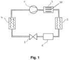
- figure 1 schematically represents a heat pump according to an advantageous embodiment of the present invention.
- the closed circuit comprises the fluid compressor 1 and a fluid return circuit to the compressor.
- the compressor extends in the closed circuit between the fluid inlet and the fluid outlet, the return circuit extending in the closed circuit, complementary to the compressor, between the fluid outlet and the fluid inlet.
- the return circuit comprises the condenser 2, the expansion valve 3 and the evaporator 4. Said return circuit thus comprises a first pipe extending between the fluid outlet and the condenser, a second pipe extending between the condenser and the expansion valve, a third pipe extending between the expansion valve and the evaporator, and a fourth pipe extending between the evaporator and the fluid inlet.
- said closed circuit comprises a first bulge 5 of a return circuit pipe containing pipes 50, the fluid comprising a mixture of a first freon R32 (difluoromethane), a second freon R125 (pentafluoroethane) and a third freon R134a (1,1,1,2-tetrafluoroethane), and the lubricant comprises a synthetic polyolester oil.
- FIG. 1 represents a heat pump provided with two pipe bulges: a first pipe bulge 5, with pipes 50, arranged between a fluid outlet of the compressor 1 of the pump and a condenser 2 of the pump and a second bulge 6 without pipes arranged between the condenser 2 and the expansion valve 3 of the pump.
- the pump also has an evaporator 4.
- a single bulge is also possible.
- the invention can also be implemented with an AIRMEC ® heat pump of model reference ANF 50 with a power of 15kW or ANF 100 with a power equal to 35kW.
- the invention is therefore not limited to a particular manufacturer or model.
- the pump may use a set of copper pipes with an internal diameter of fourteen millimetres (14 mm) forming a closed circuit sealed against gases and liquids, the closed circuit being immersed in the atmosphere.
- a compressor 1 of reference ZB38KCE having a fluid inlet and a fluid outlet.
- the first tube bulge is formed, on a first 14 mm pipe, by a local increase in the internal diameter of the pipe or first bulge.
- This first bulge 5 contains internal tubes 50, for example seven tubes with an internal diameter of 5 mm for an external diameter of 8.5 mm, surrounded by the first bulge of the pipe.
- the internal diameter of the bulge is adapted to be able to enclose the tubes and the thickness of the bulge is adapted to support the maximum pressure specified for the fluid in this part of the pump.
- the inner diameter of the bulge is for 7 tubes arranged compactly, equal to 3 times the outer diameter of a tube or approximately 25.5mm. For a larger number of tubes, this inner diameter of the bulge can be deduced as being the outer diameter of the tubes, compactly packed.
- the same ratio between the diameter of the pipes and the diameter of the pipe will be chosen as that of this first embodiment, i.e. here a ratio equal to 14mm/5mm or 2.8.
- the length of the pipes of the first bulge will be taken as approximately 22 cm for an original AERMEC ® pump and 13 cm for an original AIRWELL ® pump.
- the condenser a known element, is encountered in the circuit following the first bulge.
- the second bulge is designed to operate in the liquid phase for the refrigerant and the oil, it is for example identical to the first bulge but it may or may not include pipes, these not having been recognized as essential for obtaining the effect of the invention with the second bulge present in the circuit in addition to the first bulge.
- the second bulge is followed, downstream, by the expansion valve.
- the expansion valve is a known element, operating in the mainly liquid phase, at its inlet, and designed to produce a two-phase mixture of gas and liquid in the normal operation of the heat pump of the invention.
- the expansion valve is followed downstream of the evaporator, a known element.
- the pump In heating mode use, the pump is brought into contact at the evaporator with the atmosphere surrounding an enclosure to be heated and at the condenser with a heating circuit of the enclosure.
- the pump In cooling mode operation, the pump is placed in contact at the evaporator with an enclosure to be cooled and at the condenser with the atmosphere surrounding the enclosure.
- Known fluidic valves can allow switching on a user action from a heating mode to a cooling mode, if the pump according to the invention must be reversible.
- freon chosen for all pumps is R407C or R407A freon and the oil is EMKARATE ® RL32-3 MAF oil, miscible with the chosen freon at all operating temperatures.
- a refrigerant or cooling fluid and an oil which are miscible with each other will be used.
- the family of refrigerant fluids consisting of freons with the name R407 and oils miscible with the freons of this family constitute in particular a set of fluids which can be used with the invention.
- the general principle of the invention is considered at the date of the patent to be the ability to transport the oil of a heat pump, in the form of an emulsion of oil drops, suitable for increasing the heat exchanges in the condenser and in the evaporator of the pump.
- the means of the invention which are the first and second bulges therefore tend to regenerate or maintain this emulsion in its form suitable for improving the operation of the heat exchangers (condenser and evaporator) of the pump.
- drops taken as synonyms for bubbles (containing gas) in a gaseous transport medium or drops taken as synonyms for "antibubbles" (oil bubbles containing gas) in a liquid transport medium, is considered to provide nucleation sites for the condensation of the transport medium or for the evaporation of this medium, promoting heat exchanges, during its phase changes in the pump exchangers.
- This emulsion is estimated, in the gas phase, to be a mist of droplets forming a "monodispersed" oil emulsion, in a gas phase (i.e. droplets whose diameter values are strongly centered on a common value) with a sufficient lifetime to reach the condenser and improve heat exchanges there.
- the invention therefore uses a first means of forming an oil mist between the compressor and the condenser.
- a particular means is thus a means of imposing a depression on drops of oil having absorbed a transport refrigerant gas due to the solubility of the gas in the oil and causing the appearance of gas bubbles in the drops capable of bursting into finer droplets.
- This emulsion is estimated, in liquid phase, to be a mixture of oil droplets forming a "monodispersed" oil emulsion, in a liquid phase, of sufficient lifetime to reach the expander, pass through it, reach the evaporator and improve heat exchanges there, to finally return to the compressor regularly over time and in the form of an oil mist of regular oil droplet diameter and improve its isentropic efficiency by improved lubrication, compared to a commercial pump.
- the invention thus uses, to improve the COP of a heat pump, a first means of forming an oil mist between the compressor and the condenser and a second means of forming a dispersion of oil drops in liquid phase between the condenser and the compressor, these drops being able to burst into droplets or bubbles when passing through the expansion valve and reaching the evaporator.
- the elements of the invention namely the first tube bulge and the second bulge, can thus be adapted by those skilled in the art to achieve this goal.
- thermodynamic efficiency or the COP of an entire heat pump using one or two bulges, a particular refrigerant and an oil miscible with the fluid was therefore not expected in the prior art.
- the effect obtained makes it possible to envisage heating or cooling uses with a pump equipped with at least one bulge.
- the first bulge is composed along its length, running through the closed circuit from the compressor fluid outlet on the first pipe joining the compressor fluid outlet to the condenser, of a first zone of increase in the internal diameter of the pipe, of a second zone of constant internal diameter of the pipe and of a third zone of reduction in the internal diameter of the pipe.
- the change in diameter of the first zone can be carried out by a first cone whose apex angle allows, for the normal fluid operating conditions of the pump, to cause a separation of the current lines of the fluid flowing through the pump.
- the change in diameter of the third zone can be carried out by a second cone whose apex angle allows, for the normal fluid operating conditions of the pump, not to cause a separation of the current lines of the fluid flowing through the pump.
- the second zone of the first bulge will advantageously be arranged vertically, when the refrigerant is a mixture of freons and oil.
- This zone will thus have a chimney arrangement or a chimney or vertical duct function for the first swelling, which normally operates with gaseous refrigerant and oil drops.
- This arrangement will allow heat transfer to the condenser and not heat production not reaching the condenser by increasing the life of the freon emulsion and oil drops after the fluid has passed through the first bulge and allowing them to reach the condenser despite coalescence.
- Such a vertical structure allows, for a soluble freon or a mixture of soluble freons in an oil present in drops transported with the gas, numerous simultaneous effects resulting in creating or regenerating a stable emulsion over time of gas and oil, such as that conventionally produced by the compressor, at its discharge outlet, and in which the drops are usually "polydispersed" (i.e. widely variable around a central value) in diameter.
- a change in the circulating composition of the mixture initially introduced into the fluid circuit may be an indication of operation of the invention.
- the compositions of the mixture measured at the compressor outlet, over time depending on the operating conditions: outside temperature, temperature of the hydraulic circuit, setting of the expansion valve. Since the differential solubility of the components of R407C in the oil is variable, trapping of the oil in the tubes of the first bulge may also explain this variation in circulating composition.
- the person skilled in the art in the presence of such an increase, will be able to adjust the length of the tubes or adjust the distance separating the first bulge from the condenser, in the fluid circuit, to optimize the increase in power observed in the condenser, for example by measuring the temperature of a hot water outlet of a heating circuit in thermal contact with the condenser. He will also be able to vary the verticality of the tubes by admitting an angle maintaining a slope to the tubes allowing the flow of oil downwards, maintaining an effect on the thermal power of the condenser compared to a strict verticality.
- the COP improvement percentages for R407C, R407A and R407F are as follows: 407C 407A 407F Ambient air COP gain COP gain COP gain 7°C 27% 21% -3% 0°C 34% 23% 12% -7°C 37% 14% 3%
- this structure is designed to provide a means of regularly dividing the oil drops with the result of forming an emulsion of drops and gas sufficiently stable, in terms of droplet lifetime, to allow them to reach the condenser and form nucleation sites improving heat exchange in the condenser and the thermodynamic efficiency of the pump.
- the same general inventive idea of a means of forming an emulsion will be applied to the design of the first bulge with tubes but instead of an emulsion of drops in a gas or gases, the first bulge will be designed to form an emulsion of bubbles in the gas or gases.
- a mixed mode in which an emulsion of drops but also of oil bubbles is formed by the first bulge between the oil and the freons present in the first line is not excluded depending on the relative surface tension properties of the oil and the freons at the operating temperature and pressure of the fluid in the first line.
- the invention was tested with mixtures of freons R32, R125 and R134a induced by an introduction of R407C and a particular oil EMKARATE ® RL32-3 MAF in the circuit of a pump modified by the first bulge arranged vertically and having the second bulge.
- a compressor (referenced ZB38KCE) is used.
- the oil is considered in liquid form throughout the closed circuit at the temperatures and pressures mentioned.
- the mixture of R32, R125 and R134a is gaseous at the outlet. There is therefore, in normal operation in this embodiment, no increase in temperature at the outlet of the first bulge compared to its inlet, and this bulge therefore does not function as a heat source.
- the mixture of R32, R125 and R134a is liquid at the outlet.
- the mixture of R32, R125 and R134a is liquid at the outlet, with liquid-gas two-phase periods, where bubbles appear. There is therefore, in normal operation in this embodiment, no increase in temperature at the outlet of the second bulge compared to its inlet, and this bulge therefore does not function as a heat source.
- the mixture of R32, R125 and R134a is two-phase liquid-gas at the outlet.
- the mixture of R32, R125 and R134a is gaseous at the outlet.
- the COP gains are comparable to those of an AIRWELL ® brand machine mentioned previously for the first mode, over the temperature range from -7°C to +7°C.
- the invention is susceptible to industrial application in the field of heat pumps and air conditioners.
Landscapes
- Engineering & Computer Science (AREA)
- Physics & Mathematics (AREA)
- Mechanical Engineering (AREA)
- Thermal Sciences (AREA)
- General Engineering & Computer Science (AREA)
- Lubricants (AREA)
- Compression-Type Refrigeration Machines With Reversible Cycles (AREA)
- Compressor (AREA)
- Structures Of Non-Positive Displacement Pumps (AREA)
Claims (12)
- Wärmepumpe, aufweisend einen geschlossenen Kreislauf, der ein fluides Kältemittel und ein Schmiermittel enthält, wobei der geschlossene Kreislauf einen Kompressor (1) für das fluide Kältemittel und einen Rückführungskreislauf für das Fluid zum Kompressor aufweist, wobei sich der Kompressor in dem geschlossenen Kreislauf zwischen einem Fluideinlass und einem Fluidauslass erstreckt, wobei sich der Rückführungskreislauf in dem geschlossenen Kreislauf komplementär zum Kompressor zwischen dem Fluidauslass und dem Fluideinlass erstreckt, wobei der Rückführungskreislauf einen Kondensator (2), ein Druckminderungsventil (3) und einen Verdampfer (4) aufweist, wobei der Rückführungskreislauf eine erste Leitung aufweist, die sich zwischen dem Fluidauslass und dem Kondensator erstreckt, eine zweite Leitung, die sich zwischen dem Kondensator und dem Druckminderungsventil erstreckt, eine dritte Leitung, die sich zwischen dem Druckminderungsventil und dem Verdampfer erstreckt, und eine vierte Leitung, die sich zwischen dem Verdampfer und dem Fluideinlass erstreckt, wobei das Fluid eine Mischung aus einem ersten Freon R32 (Difluormethan), einem zweiten Freon R125 (Pentafluorethan) und einem dritten Freon R134a (1,1,1,2-Tetrafluorethan) aufweist und das Schmiermittel ein synthetisches Polyolesteröl aufweist,
wobei die Pumpe dadurch gekennzeichnet ist, dass der geschlossene Kreislauf eine erste Ausbuchtung (5) einer Leitung des Rücklaufkreislaufs aufweist, wobei die erste Ausbuchtung (5) an der ersten Leitung angeordnet ist, um Tropfen des Schmiermittels mit einem Unterdruck zu beaufschlagen und dadurch das Auftreten von Gasblasen in den Tropfen zu bewirken, die geeignet sind, in feinere Tröpfchen zu zerplatzen, so dass ein Nebel aus Schmiermittel zwischen dem Kompressor (1) und dem Kondensator (2) gebildet wird, wobei die erste Ausbuchtung (5) vertikal angeordnete Rohrleitungen (50) zum Auswählen und Transportieren von Tröpfchen, die durch die erste Ausbuchtung (5) erzeugt werden, enthält. - Pumpe nach Anspruch 1, wobei der geschlossene Kreislauf eine zweite Ausbuchtung (6) einer Leitung des Rücklaufkreislaufs aufweist.
- Pumpe nach Anspruch 2, wobei die zweite Ausbuchtung (6) an der zweiten Leitung angeordnet ist.
- Pumpe nach einem der vorhergehenden Ansprüche, wobei das synthetische Polyolesteröl der ISO-Klasse VG 32 entspricht.
- Pumpe nach einem der vorhergehenden Ansprüche, wobei das Kältemittel ein Freon R407C ist.
- Pumpe nach einem der Ansprüche 1 bis 4, wobei das Kältemittel ein Freon R407A ist.
- Pumpe nach einem der vorhergehenden Ansprüche, wobei die erste Ausbuchtung (5) vertikal angeordnet ist.
- Pumpe nach Anspruch 7, wobei die erste Ausbuchtung (5) vertikal und in aufsteigendem Fluid angeordnet ist.
- Pumpe nach Anspruch 2 und einem der Ansprüche 3 bis 8, wobei die zweite Ausbuchtung (6) vertikal angeordnet ist.
- Verwendung einer Wärmepumpe nach einem der Ansprüche 1 bis 9 zum Zwecke der Beheizung eines Gehäuses, wobei der Verdampfer (4) in thermischen Kontakt mit der Außenseite des Gehäuses gebracht wird und der Kondensator (2) in thermischen Kontakt mit der Innenseite des Gehäuses gebracht wird, um den thermodynamischen Wirkungsgrad des Heizvorgangs zu verbessern.
- Verwendung einer Wärmepumpe nach einem der Ansprüche 1 bis 9 zum Zwecke der Kühlung eines Gehäuses, wobei der Verdampfer (4) in thermischen Kontakt mit dem Inneren des Gehäuses gebracht wird und der Kondensator (2) in thermischen Kontakt mit der Außenseite des Gehäuses gebracht wird, um den thermodynamischen Wirkungsgrad des Kühlvorgangs zu verbessern.
- Verwendung nach Anspruch 10 oder 11, bei der das Kältemittel in der ersten Ausbuchtung (5) aufsteigt.
Applications Claiming Priority (2)
| Application Number | Priority Date | Filing Date | Title |
|---|---|---|---|
| FR1361503A FR3013812B1 (fr) | 2013-11-22 | 2013-11-22 | Pompe a chaleur. |
| PCT/FR2014/052987 WO2015075393A1 (fr) | 2013-11-22 | 2014-11-21 | Dispositif a fluide frigorigene pour l'augmentation du rendement thermodynamique |
Publications (3)
| Publication Number | Publication Date |
|---|---|
| EP3071902A1 EP3071902A1 (de) | 2016-09-28 |
| EP3071902C0 EP3071902C0 (de) | 2025-02-19 |
| EP3071902B1 true EP3071902B1 (de) | 2025-02-19 |
Family
ID=50473400
Family Applications (1)
| Application Number | Title | Priority Date | Filing Date |
|---|---|---|---|
| EP14824056.7A Active EP3071902B1 (de) | 2013-11-22 | 2014-11-21 | Kühlflüssigkeitsvorrichtung zur erhöhung der thermodynamischen leistung |
Country Status (12)
| Country | Link |
|---|---|
| US (1) | US10274234B2 (de) |
| EP (1) | EP3071902B1 (de) |
| JP (1) | JP6364090B2 (de) |
| KR (1) | KR102246125B1 (de) |
| CN (1) | CN106415155B (de) |
| AU (1) | AU2014351648B2 (de) |
| BR (1) | BR112016011701B1 (de) |
| ES (1) | ES3022583T3 (de) |
| FR (1) | FR3013812B1 (de) |
| PL (1) | PL3071902T3 (de) |
| RU (1) | RU2677315C1 (de) |
| WO (1) | WO2015075393A1 (de) |
Families Citing this family (2)
| Publication number | Priority date | Publication date | Assignee | Title |
|---|---|---|---|---|
| JP6315071B1 (ja) * | 2016-11-28 | 2018-04-25 | ダイキン工業株式会社 | 冷媒組成物の移充填方法 |
| CN116972557A (zh) * | 2023-07-26 | 2023-10-31 | 广东美的暖通设备有限公司 | 冷媒循环系统及空调器 |
Family Cites Families (16)
| Publication number | Priority date | Publication date | Assignee | Title |
|---|---|---|---|---|
| JPS5040122Y2 (de) * | 1971-10-20 | 1975-11-17 | ||
| US4214453A (en) * | 1979-02-09 | 1980-07-29 | Barrow Billy E | Injector cooler controls |
| US4478050A (en) * | 1982-11-19 | 1984-10-23 | Hussmann Corporation | Oil separation for refrigeration system |
| JPS6315058A (ja) | 1986-07-04 | 1988-01-22 | 株式会社デンソー | 冷凍サイクル |
| JP4294764B2 (ja) * | 1998-09-10 | 2009-07-15 | 三菱電機株式会社 | 冷凍サイクル |
| JP2001317840A (ja) * | 2000-05-09 | 2001-11-16 | Mitsubishi Electric Corp | 減圧装置、冷凍回路、ヒートポンプ式空気調和機、減圧装置の製造方法 |
| JP2002106959A (ja) * | 2000-09-28 | 2002-04-10 | Sanyo Electric Co Ltd | ヒートポンプ給湯機 |
| DE102004038220B4 (de) * | 2004-08-05 | 2009-07-23 | Proton Technology Gmbh I.Gr. | Thermische Biomassenverölung |
| JP2006266636A (ja) * | 2005-03-25 | 2006-10-05 | Daikin Ind Ltd | 冷凍装置 |
| CN101432385A (zh) * | 2005-06-08 | 2009-05-13 | 开利公司 | 以节约器操作空调系统的方法和装置 |
| MX2009014089A (es) | 2007-07-05 | 2010-03-01 | Ib Ntec | Un dispositivo para producir calor al circular un fluido bajo presion a traves de una pluralidad de tubos, y un sistema termodinamico que implementa tal dispositivo. |
| WO2009053726A2 (en) * | 2007-10-24 | 2009-04-30 | Thermal Energy Systems Limited | Heat pump |
| WO2011028970A1 (en) | 2009-09-04 | 2011-03-10 | E. I. Du Pont De Nemours And Company | Compositions comprising refrigerant and lubricant and methods for replacing cfc and hcfc refrigerants without flushingfield of the invention |
| CN201724472U (zh) * | 2010-07-30 | 2011-01-26 | 中国汽车工业工程公司 | 直接膨胀式土壤源热泵的回油控制装置 |
| CN102003844B (zh) * | 2010-12-07 | 2012-01-18 | 东南大学 | 一种高效全湿内表面蒸发器 |
| FR2990264B1 (fr) * | 2012-05-04 | 2018-07-27 | Valeo Systemes Thermiques | Installation de chauffage, ventilation et/ou climatisation a masse circulante reduite. |
-
2013
- 2013-11-22 FR FR1361503A patent/FR3013812B1/fr active Active
-
2014
- 2014-11-21 BR BR112016011701-8A patent/BR112016011701B1/pt active IP Right Grant
- 2014-11-21 KR KR1020167016353A patent/KR102246125B1/ko active Active
- 2014-11-21 AU AU2014351648A patent/AU2014351648B2/en active Active
- 2014-11-21 CN CN201480073862.5A patent/CN106415155B/zh active Active
- 2014-11-21 PL PL14824056.7T patent/PL3071902T3/pl unknown
- 2014-11-21 WO PCT/FR2014/052987 patent/WO2015075393A1/fr not_active Ceased
- 2014-11-21 ES ES14824056T patent/ES3022583T3/es active Active
- 2014-11-21 US US15/038,209 patent/US10274234B2/en active Active
- 2014-11-21 JP JP2016554921A patent/JP6364090B2/ja active Active
- 2014-11-21 RU RU2016124553A patent/RU2677315C1/ru active
- 2014-11-21 EP EP14824056.7A patent/EP3071902B1/de active Active
Also Published As
| Publication number | Publication date |
|---|---|
| FR3013812B1 (fr) | 2019-03-15 |
| KR102246125B1 (ko) | 2021-04-30 |
| WO2015075393A1 (fr) | 2015-05-28 |
| EP3071902C0 (de) | 2025-02-19 |
| US10274234B2 (en) | 2019-04-30 |
| FR3013812A1 (fr) | 2015-05-29 |
| PL3071902T3 (pl) | 2025-07-07 |
| US20160290687A1 (en) | 2016-10-06 |
| BR112016011701B1 (pt) | 2022-03-22 |
| RU2677315C1 (ru) | 2019-01-16 |
| AU2014351648B2 (en) | 2018-10-18 |
| RU2016124553A (ru) | 2017-12-27 |
| KR20160089424A (ko) | 2016-07-27 |
| AU2014351648A1 (en) | 2016-06-09 |
| CN106415155A (zh) | 2017-02-15 |
| EP3071902A1 (de) | 2016-09-28 |
| ES3022583T3 (en) | 2025-05-28 |
| JP2016539313A (ja) | 2016-12-15 |
| JP6364090B2 (ja) | 2018-07-25 |
| CN106415155B (zh) | 2020-06-26 |
| BR112016011701A2 (de) | 2017-08-08 |
Similar Documents
| Publication | Publication Date | Title |
|---|---|---|
| EP2475737B2 (de) | Wärmeübertragungsverfahren | |
| EP2475732B1 (de) | Ternäre zusammensetzungen für leistungsstarke kühlung | |
| EP3044278B1 (de) | Wärmeübertragungsflüssigkeiten mit difluormethan, pentafluorethan, tetrafluorpropen und optional propan | |
| EP3071902B1 (de) | Kühlflüssigkeitsvorrichtung zur erhöhung der thermodynamischen leistung | |
| CN1526061A (zh) | 冷冻循环装置 | |
| EP3071901B1 (de) | Vorrichtung zur verwendung mit einer kühlflüssigkeit zur erhöhung der thermodynamischen leistung | |
| WO2007090861A1 (fr) | Dispositif echangeur de chaleur destine aux systemes de chauffage ou de climatisation | |
| EP3601469A1 (de) | Verfahren zur beheizung und/oder klimatisierung eines fahrzeuges | |
| CA2844478A1 (fr) | Fluides de transfert de chaleur supercritiques a base de tetrafluoropropene | |
| EP2708436A1 (de) | Klimaanlagenvorrichtung, insbesondere für Schienenfahrzeug | |
| WO2015075394A1 (fr) | Procede d'augmentation du rendement d'un dispositif thermodynamique a fluide frigorigene | |
| FR2986309A1 (fr) | Systeme de refrigeration en cascade | |
| WO2015104330A1 (fr) | Pompe à chaleur produisant du froid | |
| EP2411743A1 (de) | Anlage und verfahren zur erzeugung von kälte und/oder wärme | |
| WO2024156698A1 (fr) | Amélioration de la puissance des machines thermodynamiques | |
| EP1956328A1 (de) | Zweiphasiger Wärmetauscher | |
| FR3033796A1 (fr) | Fluide frigorigene |
Legal Events
| Date | Code | Title | Description |
|---|---|---|---|
| PUAI | Public reference made under article 153(3) epc to a published international application that has entered the european phase |
Free format text: ORIGINAL CODE: 0009012 |
|
| 17P | Request for examination filed |
Effective date: 20160609 |
|
| AK | Designated contracting states |
Kind code of ref document: A1 Designated state(s): AL AT BE BG CH CY CZ DE DK EE ES FI FR GB GR HR HU IE IS IT LI LT LU LV MC MK MT NL NO PL PT RO RS SE SI SK SM TR |
|
| AX | Request for extension of the european patent |
Extension state: BA ME |
|
| RIN1 | Information on inventor provided before grant (corrected) |
Inventor name: CASTELAIN, GILLES Inventor name: MORO-PEREZ, JIMMY Inventor name: KALINOWSKI, PASCAL Inventor name: RIZK, JOELLE Inventor name: DEBOUX, BRUNO Inventor name: BARBAN, FREDERIC |
|
| DAX | Request for extension of the european patent (deleted) | ||
| STAA | Information on the status of an ep patent application or granted ep patent |
Free format text: STATUS: EXAMINATION IS IN PROGRESS |
|
| 17Q | First examination report despatched |
Effective date: 20190925 |
|
| GRAP | Despatch of communication of intention to grant a patent |
Free format text: ORIGINAL CODE: EPIDOSNIGR1 |
|
| STAA | Information on the status of an ep patent application or granted ep patent |
Free format text: STATUS: GRANT OF PATENT IS INTENDED |
|
| INTG | Intention to grant announced |
Effective date: 20240911 |
|
| GRAS | Grant fee paid |
Free format text: ORIGINAL CODE: EPIDOSNIGR3 |
|
| GRAA | (expected) grant |
Free format text: ORIGINAL CODE: 0009210 |
|
| STAA | Information on the status of an ep patent application or granted ep patent |
Free format text: STATUS: THE PATENT HAS BEEN GRANTED |
|
| AK | Designated contracting states |
Kind code of ref document: B1 Designated state(s): AL AT BE BG CH CY CZ DE DK EE ES FI FR GB GR HR HU IE IS IT LI LT LU LV MC MK MT NL NO PL PT RO RS SE SI SK SM TR |
|
| REG | Reference to a national code |
Ref country code: GB Ref legal event code: FG4D Free format text: NOT ENGLISH |
|
| REG | Reference to a national code |
Ref country code: CH Ref legal event code: EP |
|
| REG | Reference to a national code |
Ref country code: IE Ref legal event code: FG4D Free format text: LANGUAGE OF EP DOCUMENT: FRENCH |
|
| REG | Reference to a national code |
Ref country code: DE Ref legal event code: R096 Ref document number: 602014091578 Country of ref document: DE |
|
| U01 | Request for unitary effect filed |
Effective date: 20250319 |
|
| U07 | Unitary effect registered |
Designated state(s): AT BE BG DE DK EE FI FR IT LT LU LV MT NL PT RO SE SI Effective date: 20250325 |
|
| RAP4 | Party data changed (patent owner data changed or rights of a patent transferred) |
Owner name: DYNAES |
|
| U1H | Name or address of the proprietor changed after the registration of the unitary effect |
Owner name: DYNAES; FR |
|
| REG | Reference to a national code |
Ref country code: ES Ref legal event code: FG2A Ref document number: 3022583 Country of ref document: ES Kind code of ref document: T3 Effective date: 20250528 |
|
| PG25 | Lapsed in a contracting state [announced via postgrant information from national office to epo] |
Ref country code: RS Free format text: LAPSE BECAUSE OF FAILURE TO SUBMIT A TRANSLATION OF THE DESCRIPTION OR TO PAY THE FEE WITHIN THE PRESCRIBED TIME-LIMIT Effective date: 20250519 |
|
| PG25 | Lapsed in a contracting state [announced via postgrant information from national office to epo] |
Ref country code: IS Free format text: LAPSE BECAUSE OF FAILURE TO SUBMIT A TRANSLATION OF THE DESCRIPTION OR TO PAY THE FEE WITHIN THE PRESCRIBED TIME-LIMIT Effective date: 20250619 |
|
| PG25 | Lapsed in a contracting state [announced via postgrant information from national office to epo] |
Ref country code: HR Free format text: LAPSE BECAUSE OF FAILURE TO SUBMIT A TRANSLATION OF THE DESCRIPTION OR TO PAY THE FEE WITHIN THE PRESCRIBED TIME-LIMIT Effective date: 20250219 |
|
| PG25 | Lapsed in a contracting state [announced via postgrant information from national office to epo] |
Ref country code: GR Free format text: LAPSE BECAUSE OF FAILURE TO SUBMIT A TRANSLATION OF THE DESCRIPTION OR TO PAY THE FEE WITHIN THE PRESCRIBED TIME-LIMIT Effective date: 20250520 |
|
| PG25 | Lapsed in a contracting state [announced via postgrant information from national office to epo] |
Ref country code: SM Free format text: LAPSE BECAUSE OF FAILURE TO SUBMIT A TRANSLATION OF THE DESCRIPTION OR TO PAY THE FEE WITHIN THE PRESCRIBED TIME-LIMIT Effective date: 20250219 |
|
| PG25 | Lapsed in a contracting state [announced via postgrant information from national office to epo] |
Ref country code: CZ Free format text: LAPSE BECAUSE OF FAILURE TO SUBMIT A TRANSLATION OF THE DESCRIPTION OR TO PAY THE FEE WITHIN THE PRESCRIBED TIME-LIMIT Effective date: 20250219 |
|
| PG25 | Lapsed in a contracting state [announced via postgrant information from national office to epo] |
Ref country code: SK Free format text: LAPSE BECAUSE OF FAILURE TO SUBMIT A TRANSLATION OF THE DESCRIPTION OR TO PAY THE FEE WITHIN THE PRESCRIBED TIME-LIMIT Effective date: 20250219 |
|
| PLBE | No opposition filed within time limit |
Free format text: ORIGINAL CODE: 0009261 |
|
| STAA | Information on the status of an ep patent application or granted ep patent |
Free format text: STATUS: NO OPPOSITION FILED WITHIN TIME LIMIT |
|
| U20 | Renewal fee for the european patent with unitary effect paid |
Year of fee payment: 12 Effective date: 20251125 |
|
| PGFP | Annual fee paid to national office [announced via postgrant information from national office to epo] |
Ref country code: GB Payment date: 20251120 Year of fee payment: 12 |
|
| PGFP | Annual fee paid to national office [announced via postgrant information from national office to epo] |
Ref country code: NO Payment date: 20251126 Year of fee payment: 12 |
|
| PGFP | Annual fee paid to national office [announced via postgrant information from national office to epo] |
Ref country code: TR Payment date: 20251117 Year of fee payment: 12 |
|
| PGFP | Annual fee paid to national office [announced via postgrant information from national office to epo] |
Ref country code: PL Payment date: 20251118 Year of fee payment: 12 |
|
| 26N | No opposition filed |
Effective date: 20251120 |
|
| PGFP | Annual fee paid to national office [announced via postgrant information from national office to epo] |
Ref country code: ES Payment date: 20251212 Year of fee payment: 12 |