EP3071384B1 - Vorrichtung und verfahren zum trennen von unterschiedlichen arten von materialien - Google Patents
Vorrichtung und verfahren zum trennen von unterschiedlichen arten von materialien Download PDFInfo
- Publication number
- EP3071384B1 EP3071384B1 EP14828283.3A EP14828283A EP3071384B1 EP 3071384 B1 EP3071384 B1 EP 3071384B1 EP 14828283 A EP14828283 A EP 14828283A EP 3071384 B1 EP3071384 B1 EP 3071384B1
- Authority
- EP
- European Patent Office
- Prior art keywords
- mixture
- fraction
- materials
- receiving
- metal surface
- Prior art date
- Legal status (The legal status is an assumption and is not a legal conclusion. Google has not performed a legal analysis and makes no representation as to the accuracy of the status listed.)
- Not-in-force
Links
- 239000000463 material Substances 0.000 title claims description 153
- 238000000034 method Methods 0.000 title claims description 27
- 239000000203 mixture Substances 0.000 claims description 117
- 239000002184 metal Substances 0.000 claims description 82
- 238000000926 separation method Methods 0.000 claims description 57
- CURLTUGMZLYLDI-UHFFFAOYSA-N Carbon dioxide Chemical compound O=C=O CURLTUGMZLYLDI-UHFFFAOYSA-N 0.000 claims description 53
- 238000010438 heat treatment Methods 0.000 claims description 45
- 239000000126 substance Substances 0.000 claims description 37
- 239000002245 particle Substances 0.000 claims description 28
- 229920000139 polyethylene terephthalate Polymers 0.000 claims description 28
- 239000005020 polyethylene terephthalate Substances 0.000 claims description 27
- 229910002092 carbon dioxide Inorganic materials 0.000 claims description 26
- 239000001569 carbon dioxide Substances 0.000 claims description 22
- 238000007790 scraping Methods 0.000 claims description 20
- 239000012634 fragment Substances 0.000 claims description 19
- 238000001816 cooling Methods 0.000 claims description 16
- 230000009471 action Effects 0.000 claims description 14
- 230000005484 gravity Effects 0.000 claims description 14
- 230000005674 electromagnetic induction Effects 0.000 claims description 12
- 235000011837 pasties Nutrition 0.000 claims description 10
- 238000011144 upstream manufacturing Methods 0.000 claims description 10
- 235000011089 carbon dioxide Nutrition 0.000 claims description 9
- 239000007787 solid Substances 0.000 claims description 9
- 238000009826 distribution Methods 0.000 claims description 7
- 238000004064 recycling Methods 0.000 claims description 6
- 230000000875 corresponding effect Effects 0.000 claims description 4
- 238000003860 storage Methods 0.000 claims description 4
- 230000002596 correlated effect Effects 0.000 claims description 3
- -1 polyethylene terephthalate Polymers 0.000 claims description 3
- 238000005406 washing Methods 0.000 claims description 2
- 230000003213 activating effect Effects 0.000 claims 1
- 230000001419 dependent effect Effects 0.000 claims 1
- 238000002844 melting Methods 0.000 description 22
- 239000004800 polyvinyl chloride Substances 0.000 description 13
- 229920000915 polyvinyl chloride Polymers 0.000 description 12
- 229920003023 plastic Polymers 0.000 description 10
- 239000004033 plastic Substances 0.000 description 10
- 230000008018 melting Effects 0.000 description 7
- 239000004793 Polystyrene Substances 0.000 description 6
- 238000005265 energy consumption Methods 0.000 description 5
- 230000008901 benefit Effects 0.000 description 4
- 230000000694 effects Effects 0.000 description 4
- 229920002223 polystyrene Polymers 0.000 description 4
- 230000008569 process Effects 0.000 description 4
- 239000008187 granular material Substances 0.000 description 3
- 230000006872 improvement Effects 0.000 description 3
- 238000005488 sandblasting Methods 0.000 description 3
- NIXOWILDQLNWCW-UHFFFAOYSA-N acrylic acid group Chemical group C(C=C)(=O)O NIXOWILDQLNWCW-UHFFFAOYSA-N 0.000 description 2
- 238000010276 construction Methods 0.000 description 2
- 239000006185 dispersion Substances 0.000 description 2
- 230000006698 induction Effects 0.000 description 2
- 238000011084 recovery Methods 0.000 description 2
- 238000007670 refining Methods 0.000 description 2
- XLYOFNOQVPJJNP-UHFFFAOYSA-N water Substances O XLYOFNOQVPJJNP-UHFFFAOYSA-N 0.000 description 2
- 229910000831 Steel Inorganic materials 0.000 description 1
- 230000001464 adherent effect Effects 0.000 description 1
- 230000001070 adhesive effect Effects 0.000 description 1
- 238000004140 cleaning Methods 0.000 description 1
- 239000000356 contaminant Substances 0.000 description 1
- 239000012809 cooling fluid Substances 0.000 description 1
- 230000002542 deteriorative effect Effects 0.000 description 1
- 230000007613 environmental effect Effects 0.000 description 1
- 239000011810 insulating material Substances 0.000 description 1
- 238000009413 insulation Methods 0.000 description 1
- 230000001678 irradiating effect Effects 0.000 description 1
- 239000007788 liquid Substances 0.000 description 1
- 238000005457 optimization Methods 0.000 description 1
- 244000045947 parasite Species 0.000 description 1
- 238000002360 preparation method Methods 0.000 description 1
- 230000009467 reduction Effects 0.000 description 1
- 230000035939 shock Effects 0.000 description 1
- 238000007711 solidification Methods 0.000 description 1
- 230000008023 solidification Effects 0.000 description 1
- 230000003068 static effect Effects 0.000 description 1
- 239000010959 steel Substances 0.000 description 1
- 239000002699 waste material Substances 0.000 description 1
Images


Classifications
-
- B—PERFORMING OPERATIONS; TRANSPORTING
- B29—WORKING OF PLASTICS; WORKING OF SUBSTANCES IN A PLASTIC STATE IN GENERAL
- B29B—PREPARATION OR PRETREATMENT OF THE MATERIAL TO BE SHAPED; MAKING GRANULES OR PREFORMS; RECOVERY OF PLASTICS OR OTHER CONSTITUENTS OF WASTE MATERIAL CONTAINING PLASTICS
- B29B17/00—Recovery of plastics or other constituents of waste material containing plastics
- B29B17/02—Separating plastics from other materials
-
- C—CHEMISTRY; METALLURGY
- C08—ORGANIC MACROMOLECULAR COMPOUNDS; THEIR PREPARATION OR CHEMICAL WORKING-UP; COMPOSITIONS BASED THEREON
- C08J—WORKING-UP; GENERAL PROCESSES OF COMPOUNDING; AFTER-TREATMENT NOT COVERED BY SUBCLASSES C08B, C08C, C08F, C08G or C08H
- C08J11/00—Recovery or working-up of waste materials
- C08J11/04—Recovery or working-up of waste materials of polymers
- C08J11/06—Recovery or working-up of waste materials of polymers without chemical reactions
-
- B—PERFORMING OPERATIONS; TRANSPORTING
- B29—WORKING OF PLASTICS; WORKING OF SUBSTANCES IN A PLASTIC STATE IN GENERAL
- B29B—PREPARATION OR PRETREATMENT OF THE MATERIAL TO BE SHAPED; MAKING GRANULES OR PREFORMS; RECOVERY OF PLASTICS OR OTHER CONSTITUENTS OF WASTE MATERIAL CONTAINING PLASTICS
- B29B17/00—Recovery of plastics or other constituents of waste material containing plastics
- B29B17/02—Separating plastics from other materials
- B29B2017/0203—Separating plastics from plastics
-
- B—PERFORMING OPERATIONS; TRANSPORTING
- B29—WORKING OF PLASTICS; WORKING OF SUBSTANCES IN A PLASTIC STATE IN GENERAL
- B29B—PREPARATION OR PRETREATMENT OF THE MATERIAL TO BE SHAPED; MAKING GRANULES OR PREFORMS; RECOVERY OF PLASTICS OR OTHER CONSTITUENTS OF WASTE MATERIAL CONTAINING PLASTICS
- B29B17/00—Recovery of plastics or other constituents of waste material containing plastics
- B29B17/02—Separating plastics from other materials
- B29B2017/0213—Specific separating techniques
- B29B2017/0255—Specific separating techniques using different melting or softening temperatures of the materials to be separated
- B29B2017/0258—Specific separating techniques using different melting or softening temperatures of the materials to be separated using heated surfaces for selective softening or melting of at least one plastic ingredient
-
- B—PERFORMING OPERATIONS; TRANSPORTING
- B29—WORKING OF PLASTICS; WORKING OF SUBSTANCES IN A PLASTIC STATE IN GENERAL
- B29K—INDEXING SCHEME ASSOCIATED WITH SUBCLASSES B29B, B29C OR B29D, RELATING TO MOULDING MATERIALS OR TO MATERIALS FOR MOULDS, REINFORCEMENTS, FILLERS OR PREFORMED PARTS, e.g. INSERTS
- B29K2067/00—Use of polyesters or derivatives thereof, as moulding material
- B29K2067/003—PET, i.e. poylethylene terephthalate
-
- C—CHEMISTRY; METALLURGY
- C08—ORGANIC MACROMOLECULAR COMPOUNDS; THEIR PREPARATION OR CHEMICAL WORKING-UP; COMPOSITIONS BASED THEREON
- C08J—WORKING-UP; GENERAL PROCESSES OF COMPOUNDING; AFTER-TREATMENT NOT COVERED BY SUBCLASSES C08B, C08C, C08F, C08G or C08H
- C08J2367/00—Characterised by the use of polyesters obtained by reactions forming a carboxylic ester link in the main chain; Derivatives of such polymers
- C08J2367/02—Polyesters derived from dicarboxylic acids and dihydroxy compounds
-
- Y—GENERAL TAGGING OF NEW TECHNOLOGICAL DEVELOPMENTS; GENERAL TAGGING OF CROSS-SECTIONAL TECHNOLOGIES SPANNING OVER SEVERAL SECTIONS OF THE IPC; TECHNICAL SUBJECTS COVERED BY FORMER USPC CROSS-REFERENCE ART COLLECTIONS [XRACs] AND DIGESTS
- Y02—TECHNOLOGIES OR APPLICATIONS FOR MITIGATION OR ADAPTATION AGAINST CLIMATE CHANGE
- Y02W—CLIMATE CHANGE MITIGATION TECHNOLOGIES RELATED TO WASTEWATER TREATMENT OR WASTE MANAGEMENT
- Y02W30/00—Technologies for solid waste management
- Y02W30/50—Reuse, recycling or recovery technologies
- Y02W30/62—Plastics recycling; Rubber recycling
Definitions
- the present invention relates to an apparatus and a method allowing to separate materials of various type based on the different respective softening temperatures.
- the apparatus and the method are particularly useful in the field of treating and recycling of plastics materials obtained from post-consumption objects, such as polyethylene terephtalate PET and other materials, from which substances and/or further contaminant materials are to be removed.
- the contaminating substances very often include polymeric materials such as poly vinyl chloride (PVC), acrylic materials, polystyrene and so-called "low-melting" materials, i.e. having relatively lower melting temperatures and softening temperatures than PET, where the softening temperature is intended as the temperature at which the material achieves a certain state of fluidity, thereby acquiring a soft or pasty consistency.
- PVC poly vinyl chloride
- acrylic materials acrylic materials
- polystyrene so-called "low-melting” materials, i.e. having relatively lower melting temperatures and softening temperatures than PET, where the softening temperature is intended as the temperature at which the material achieves a certain state of fluidity, thereby acquiring a soft or pasty consistency.
- separating systems comprising a conveyor belt which receives said mixture of flakes and fragments and is heated, by means of hot air flows dispensed by suitable internally-arranged nozzles.
- the flakes of low-melting material, particularly of PVC, in contact with the hot belt progressively acquire a soft or pasty consistency, which causes them to become sticky.
- the aim is to allow the PET flakes to drop from the belt to a suitable collection area after they have reached the end of the conveyor belt, whereas the PVC fragments are still maintained adherent to the belt for a further portion of path.
- a suitable scraper is provided to remove the PVC fragments from the belt.
- Drum separation systems are also known, which are heated from the inside by means of hot liquids or hot air, at such temperatures as to cause the softening of the low-melting materials to be removed.
- suitable scrapers remove the fragments of low-melting material attached to the drums, whereas the PET flakes are allowed to drop freely in a separate zone.
- Systems for separating different materials are, for example, known from US5303826 and US5660282 . These systems do not comprise either electromagnetic inductor heating means or dispensing means configured to direct a jet of refrigerating-cleaning substance comprising air and carbon dioxide (CO2) in a solid state i.e. dry ice.
- CO2 carbon dioxide
- the hot air heating should be necessarily provided from the inside in order to prevent the lighter mixture particles from being swept away from the supporting and advancement surfaces on which they are laid, and this implies that quite complex internal circuits should be provided for the hot air.
- the use of hot air to heat the surfaces of the belt or drums entails a considerable energy consumption.
- the hot air heating system has a number of difficulties both in terms of construction and in terms of management and operation.
- the scraping action often leads to unsatisfactory results.
- An object of the present invention is to provide a method and an apparatus which provide a general improvement in the separation of recyclable materials, compared to the known systems. Another object is to structurally simplifying the systems for separating the recyclable materials, thereby making them cost-effective in terms of construction and operation, and ensuring a high level of separation and purity of the plastics material being recovered while achieving a higher energy efficiency than the prior art systems currently used.
- a method for separating materials of various type having different softening temperature values comprising the steps of:
- an apparatus 1, 100, 200, 300, 400 is shown to separate materials of various type having different softening temperature values.
- the apparatus 1, 100, 200, 300, 400 allows to separate and recover materials of various type based on the different respective softening temperatures.
- the apparatus is thus a thermal apparatus-separator.
- the apparatus is particularly useful in the field of recovering and recycling materials, such as the materials coming from post-consumption plastic containers or bottles, such as polyethylene terephthalate PET and other materials, from which substances and/or further undesired contaminating materials are to be removed. Accordingly, the apparatus results to be a refiner apparatus capable of removing from a certain crushed material in granules or in flakes, the undesired substances or products which have a softening or melting temperature lower than the material to be purified.
- the softening temperature is the temperature at which a number of substances achieve a certain fluidity status before reaching the step of complete melting.
- a plastic material at a respective softening temperature starts acquiring a soft or pasty consistency which makes the latter sticky. This soft and pasty consistency is exploited by the apparatus and method of the present invention in order to obtain a temporary adhesion of the material to a certain surface.
- low-melting materials to designate materials having a melting temperature, and thus softening temperature lower than the main material to be depurated.
- materials such as PVC (softening temperature of 50 ⁇ 70 °C) or polystyrene PS (softening temperature of 80 ⁇ 90 °C)) can be considered low-melting materials as compared with the PET material to be depurated (which has a melting temperature of about 260 °C).
- PET polyethylene terephthalate
- the objects recovered from municipal waste and comprising bottles, or container in PET are subjected to steps of washing and removal of labels, caps and other undesired bodies such as bags or others, and are then brought to a crushing or grinding step in order to be reduced in flakes.
- These flakes of PET often result still accompanied by particles or fragments of other materials, such as polyvinylchloride PVC, polystyrene PS, other possible polymeric materials, which must be removed in order to ensure the desired purity.
- the apparatus and method according to the present invention successfully intervene, such as described below.
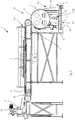
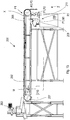
- the apparatus 1 comprises receiving and conveying means.
- the receiving and conveying means comprise support and advancing plane means 2, configured to support and advancing a blend or mixture M of flakes, or granules, fragments of different materials along a first portion of path P1, and supplying-distributing means 3 configured to pour and uniformly distribute the mixture M on said support and advancing plane means 2.
- the support and advancing plane means comprise a conveyor belt 2, actuated by a drive motor 20.
- the conveyor belt 2 has a support surface of a material suitable to resist also very high temperatures without deteriorating, such as to be able to treat any recyclable plastic material.
- the supplying-distributing means comprise a vibrating supply unit 3 provided with a hopper element, a metering star valve 12, and an inclined distribution plane 25.
- the inclined distribution plane has a slope ranging between 5 and 10 degrees but can also have different values based on the characteristics of the materials being worked.
- the vibrating supply unit 3 is actuated and vibrated by an electric motor or electromagnet or other equivalent actuating device.
- the vibrating supply unit 3 is provided with a distribution element 13 having an undulated profile which functions to uniformly distribute the mixture M thereby defining a thin layer of mixture M on the conveyor belt 2.
- the apparatus comprises pre-heating means 4 which are arranged to pre-heat the mixture M along said first portion of path P1, such as to prepare one or more types of materials included in the mixture M to a softening thermal action which is subsequently completed.
- the pre-heating means 4 are configured to irradiate thermal energy on the mixture M advancing along the first portion of path P1.
- the pre-heating means 4 are positioned outside the conveyor belt 2, at a certain distance from the movable support surface suitable to receive the mixture M.
- the thermal energy irradiated from the pre-heating means 4 must be such as not to cause the adhesion of the low-melting materials to the conveyor belt 2, but must only prepare these low-melting materials and then promote a quicker softening of the latter which is completed in a suitable section of the apparatus 1 situated downstream of the conveyor belt 2 relative to the advancing direction of the mixture M, such as described below.
- the pre-heating means 4 can pre-heat the mixture M at a temperature indicatively ranging between 120°C and 160 °C.
- the radiant power of the pre-heating means 4, and thus the pre-heating temperature can be certainly adjusted and controlled based on specific process requirements and based on the characteristic of the materials being treated, as well as the contaminating materials being present, and then can be either lower or greater than the values stated above.
- this configuration which provides the pre-heating means 4 arranged externally above at a certain distance from the support surface of the conveyor belt 2 achieves the technical effect of directing the heating action mainly and directly to the mixture M.
- the particles/fragments of mixture thereby receive the heating action in a direct manner, unlike in the prior art systems wherein it is the belt that is first heated and then it releases the heat to the mixture that is externally placed thereon. This difference is due to the fact that in the prior art systems the aim is to cause the low-melting particles to adhere directly to the conveyor belt.
- the adhesion of the low-melting materials should not occur on the conveyor belt 2 (where only a preparation for the adhesion is carried out) but on thermal separating means 5 placed downstream, which will be detailed herein below.
- the pre-heating means comprise infrared lamps 4 that are positioned above the conveyor belt 2 and distributed along the first portion of path P1, which are capable of irradiating thermal energy directly on the mixture M.
- the distribution element 13 with undulated profile of the vibrating supply unit 3, which is particularly configured to uniformly distribute the mixture M onto the conveyor belt 2 according to a thin layer of mixture M causes all the mixture flakes, particles and fragments to be in direct contact with the conveyor belt 2 and not overlap one another. This has the effect of causing each and every particle or fragment to be exposed to the heat source and invested by the action of the infrared lamps 4, thereby being heated but not adhered to the conveyor belt 2.
- a control unit 10 is provided through which the infrared lamps 4 can be controlled to adjust the proper amount of energy to be irradiated according to the recyclable materials being worked.
- the apparatus 1 comprises rotating thermal separating means 5, which are provided with a metal outer surface 6 suitable to receive the mixture M coming by gravity from the support and advancing plane means 2, (in this case, from the conveyor belt 2) and electromagnetic inductor heating means 7 configured to heat this metal outer surface 6 by means of electromagnetic induction.
- the thermal separating means particularly comprise a cylindrical unit 5 that can be a roll or a drum, rotated by a respective drive motor 21.
- the roll or drum is externally delimited by a cylindrical layer or cylindrical metal sheet, on which said outer metal surface 6 is provided.
- the metal which the outer cylindrical layer or outer cylindrical sheet, and hence said outer metal surface 6, consist of is steel or another metal suitable to be heated by electromagnetic induction.
- the cylindrical unit 5 is rotatable about a respective horizontal axis.
- the electromagnetic inductor means comprise an electric inductor element 7 situated at the outer metal surface 6.
- the electric inductor element 7 is particularly configured as a reel or electrode element extending according to a coil line, thereby defining one or more turns.
- the electric inductor element 7 can be nevertheless configured according to different shapes in order to fit the geometry of the cylindrical separation unit 5 and/or entire apparatus 1.
- an electric current is made to flow, which is alternated or in any case variable in time, which produces a time-variable magnetic field.
- the variation of the magnetic field flow generates an induced electromotive force in the metal layer or metal sheet of the separation roll 5 which, in turn, generates induced electric currents, i.e. parasite currents that dissipate energy in the form of heat thereby causing the immediate heating of the metal surface 6.
- the energy efficiency is very high, above 90%, and the energy saving is considerable.
- the induction heating on the surface 6 is quick and homogeneous, can be adjusted very precisely and be strictly localized on the zone of interest.
- the electric inductor element 7 is electrically powered by a generator with a settable power and frequency depending on several parameters, such as the geometry of the electric inductor element 7, the geometry and speed of the cylindrical separation unit 5, further possible parameters and also depending on the characteristics of the plastic material being worked which is desired to be brought to the softened condition.
- the provision of any measures for thermally insulating determined zones of the apparatus 1, particularly of the cylindrical unit 5, also positively affects the calibration of the electric inductor element 7, particularly reducing the absorbed power in order to obtain the desired heating temperature.
- a thermal insulating material which allows containing the thermal dispersions towards the inside, can be provided in the cylindrical unit 5, beneath the outer metal surface 6, thereby increasing the thermal efficacy of the system and further reducing the energy consumption.
- the electromagnetic inductor means 7 are operatively connected to, and controlled by, the control unit 10, which is provided with a temperature controller, which allows adjusting the heating temperature of the metal outer surface 6 of the roll or separation drum 5 based on the specific material intended to be softened and adhered to the latter.
- control unit 10 actuates and adjusts the electromagnetic inductor means 7 to a softening temperature TR1 of a first specific material M1 included in the mixture M, such as to maintain this first material M1 adhering to the metal outer surface 6 along a second portion of path P2, during the rotation of the cylindrical separation unit 5.
- a first fraction F1 of mixture, composed of this first material M1 is thus removed from the main stream of the mixture M.
- the cylindrical separation unit 5 is configured to cause, due to the rotation thereof, the fall by gravity, along a third portion of path P3, of a remaining part of mixture M which, unlike the first material M1, does not reach the softening state and thus does not stick to the metal outer surface 6.
- This remaining part of mixture thus defines a second fraction F2 composed of one or more materials having higher softening temperatures than the first softening temperature TR1.
- the flakes/particles of the second fraction F2 during the rotation of the roll or drum 5, advance to a curved downward trajectory having a slope gradually increasing to a point where the static friction force is no longer capable of holding the flakes which thus slip downwards from the metal surface 6 by gravity.
- the apparatus 1 further comprises scraping means 8 to remove the first fraction F1, composed of first material M1 adhering to the outer metal surface 6, in order to send it to a dedicated collection zone R1.
- a cold water circuit can be provided for cooling the scraping means 8.
- the scraping means 8 comprise a scraper for removal which can be a doctor-blade or spatula element or other element suitable to remove the particles/fragments of material that are stuck to the metal surface 6.
- the scraper 8 is located in an zone angularly spaced from the zone where the remaining part of mixture, such as the second fraction F2, detaches from the metal surface 6.
- the apparatus 1 further comprises dispensing and treatment means 11, particularly a cooling unit 11 configured to cool the first fraction F1, through a jet of a cleaning-refrigerating substance X, in order to facilitate the scraping detachment operation carried out by the scraper element 8.
- the cleaning-refrigerating substance X comprises air and carbon dioxide (CO2) at low temperature (about -78 ⁇ - 80 °C), and is directed to the first fraction F1 of mixture M to cool, solidify and crystallize the latter, such as to promote the detachment of the latter from the outer metal surface 6.
- CO2 carbon dioxide
- the effective temperature decrease to which the material to be treated is subjected causes a quick hardening of the particles of the fraction F1 thereby making them more easily detachable from the surface they are stuck to.
- the dispensing and treatment means 11 comprise one or more dispensing nozzles which act to subject the fraction F1 to treatment through the refrigerating-cleaning-substance X of air and carbon dioxide (CO2).
- the fraction F1 is subjected to a cryogenic sandblasting treatment (also designated as "cryo-sandblasting") in which pressurized air is used which contains dry ice particles, i.e. carbon dioxide (CO2) in the solid state.
- the particles of solid carbon dioxide pushed by a high-speed compressed air jet, hit the flakes, granules, fragments of material M1 thereby causing them to detach or considerably facilitate and make the next scraping step effective.
- a removal of the material is thereby obtained both due to a mechanical action of the dry ice particles and a synergy between cooling thermal shock and subsequent scraping action.
- the carbon dioxide particles after the impact go back to the gaseous state and are dissolved in the air, without leaving any residual element, and thereby without altering the physical-chemical characteristics of the material being treated. Furthermore, due to the use of the air with dry ice, the surfaces of the receiving and conveying means on which the mixture M is adhered are maintained perfectly clean.
- the refrigerating-cleaning-substance X comprises air and carbon dioxide in the state of carbon dioxide snow. Also in this case, the refrigerating-cleaning-substance X considerably facilitates the detachment of material from the respective surface to which it is adhered, does not leave any residues, and therefore does not alter the physical-chemical characteristics of the material being treated.
- the refrigerating-cleaning-substance X can be stored in a suitable storage unit 30 included in the apparatus 1.
- the dispensing and treatment means either comprise one or more nozzles 11 arranged in a stationary position, or one or more nozzles 11 mounted to a movable support, particularly translating from a zone to another in order to cover an area on which the fraction F1 of mixture is deposited, which is to be treated with said refrigerating-cleaning-substance X.
- the nozzle 11 is positioned upstream of the scraper 8 relative to the direction of rotation of the cylindrical separation unit 5, such as to cool, by solidification, the particles of material M1 that are about to interact with the scraper element 8.
- the electric inductor element 7, is positioned downstream of the scraper element 8 but upstream of the zone where the mixture M falling from the conveyor belt 2 comes from above.
- This position of the electric inductor element 7 has the technical effect of heating, immediately downstream of the scraper element 8, the subsequent portions of outer metal surface 6 which have been affected to a certain extent by the cooling action carried out by the cooling nozzle 11 and that, as soon as they have passed the scraper element 8, should be brought back again to the proper temperature before receiving again another amount of mixture M coming from the conveyor belt 2.
- a cooling unit 11 comprising an impeller blower or a blower with air compressor and a respective nozzle to expel a pressurized cold air knife, the nozzle being positioned at the respective scraper element 8, which is cooled by means of a water circuit.
- the heating of said outer metal surface 6 portions is much more quick and effective, than the prior art systems.
- the zone upstream of the scraper element 8 can be effectively and intensely cooled such that the scraping of the first material M1 can be optimized: after the scraper element 8 has been passed the cooled metal surface 6 zone is quickly brought back to the temperature suitable to cause the softening of the subsequent dose of material M1 received.
- the cylindrical separation unit 5 Due to the above-described configuration comprising the electromagnetic inductor element 7 and the cooling unit 11, and due to the particular position and mutual arrangement of the electromagnetic inductor element 7 and the cooling nozzle, the cylindrical separation unit 5 can be easily and quickly subjected to continuous local cooling and heating cycles.
- the cooling unit 11 can also be operatively connected to, and controlled by, the control unit 10.
- the control unit 10 intervenes to adjust, in a mutually related manner, based on the materials of the mixture M that is to be separated, the advance speed of the conveyor belt 2, the pre-heating temperature, the rotation speed and the temperature of the cylindrical separation unit 5, the vibratory movement of the vibrating supply unit 3 and the flow rate/pressure of the cleaning-refrigerating substance X that the cooling unit 11 directs to the cylindrical separation unit 5.
- a first material M1 e.g., PVC
- a subset of low-melting materials having the same softening temperature is separated from the remaining part of mixture
- the mixture M is continuously poured from the vibrating supply unit 3 and is uniformly distributed on the top surface of the conveyor belt 2, such as to form a thin layer of flakes/fragments/particles.
- a suitable vibratory frequency of the vibrating supply unit 3, a proper inclination of the inclined distribution plane 25 and the particular conformation of the undulated profile of the vibrating supply unit 3 result in the mixture flakes, particles and fragments being all distributed in direct contact with the conveyor belt 2, without overlapping one another, such as to be well exposed to the infrared lamps 4 to be pre-heated while they advance along the first portion of path P1.
- the flakes and particles are advantageously prevented from overlapping one another on the outer metal surface 6 upon falling onto the cylindrical separation unit 5, each of the flakes and particles thus coming in contact with the metal surface. Thereby, it is ensured that all the contaminating particles to be removed will stick to the cylindrical separation unit 5 to be then scraped away therefrom.
- the mixture M Once the mixture M has reached the end of the conveyor belt 2, it falls by gravity onto the below-located cylindrical separation unit 5, whose outer metal surface 6 is, due to the electric inductor element 7, at a first PVC-typical softening temperature TR1.
- a first fraction F1 of mixture M is thus separated whereas the remaining part of said mixture, which defines a second fraction F2 composed of materials having higher softening temperatures than the first softening temperature TR1, in this case composed of PET material, slips away by gravity from the surface of the cylindrical separation unit 5 following a third portion of path P3 and falling freely into a receiving zone Z located below, while the nozzle of the cooling unit 11 progressively cools the first fraction F1 before it reaches the scraper element 8 from which it is scraped and dropped into a PVC-dedicated collection zone R1.
- the PET being recovered is thus depurated and free of PVC traces.
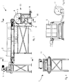
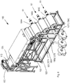
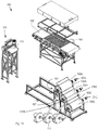
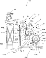
- Figs. 8 to 14 show a second embodiment of the apparatus according to the invention, designated with numeral 100.
- the apparatus 100 comprises a number of parts similar to the first embodiment described above. These parts have been designated with the same numerals as used in the first embodiment increased by 100.
- the thermal separating means comprise a plurality of cylindrical units 105, which define as many separation stages.
- three cascade-separation thermal cylindrical units 105 defining three respective separation stages for the materials of the mixture M, which are sequentially designated as first separation stage S1, second separation stage S2, and third separation stage S3.
- the apparatus 100 can be configured with a different desired number of separation thermal cylindrical units 105, and separation stages accordingly, based on particular usage requirements.
- the apparatus 100 shown in Figs. 8 to 14 comprises a first cylindrical unit 105A, which is located downstream of the conveyor belt 102 and is provided with a first metal surface 106A, a second cylindrical unit 105B having a second metal surface 106B and located beneath the first cylindrical unit 105A in a suitably offset position such that it can intercept those materials that fall from the first metal surface 106A.
- the apparatus 100 further comprises a third cylindrical unit 105C having a third metal surface 106C, which is located beneath the second cylindrical unit 105B in a suitably offset position relative to the latter such that it can intercept the materials that slip downwards from the second metal surface 106B.
- the three cylindrical separation units 105A, 105B, 105C are driven by respective motors 121A, 121B, 121C.
- the three cylindrical separation units 105A, 105B, 105C are sequentially arranged one beneath the other, and are configured to operate at progressively increasing temperatures in order to obtain separation and collection of a plurality of materials M1, M2, M3, M4 of various type having respective progressively increasing softening temperatures. Similar to the first embodiment described above, each of the three cylindrical units 105A, 105B, 105C comprises a roll or drum, which rotates about a respective horizontal axis and a respective scraper element 108A, 108B, 108C.
- the electromagnetic inductor means included in the apparatus 100 comprise for each of the three cylindrical separation units 105A, 105B and 105C, a respective electric inductor element 107A, 107B, 107C. Each electric inductor element 107A, 107B, 107C is positioned downstream of the respective scraper element 108A, 108B, 108C, relative to the direction of rotation of the respective cylindrical unit 105A, 105B, 105C.
- the cooling means 111 included in the apparatus 100 comprise, for each cylindrical unit 105A, 105B, 105C, one or more respective nozzles 111A, 111B, 111C at the respective scraper element 108A, 108B, 108C in order to direct one or more jets of cleaning-refrigerating substance X comprising pressurized air and carbon dioxide CO2 either in the solid state or in the state of carbon dioxide snow.
- the apparatus 100 includes a control unit 110 to which the drive motor 120 of the conveyor belt 102, the vibrating supply unit 103, the pre-heating means 104, the drive motors 121A, 121B, 121C of the cylindrical separation units 105A, 105B, 105C, and the electromagnetic inductor elements 107A, 107B, 107C are operatively connected.
- the cooling units 111A, 111B, 111C can also be operatively connected to, and controlled by, the control unit 110.
- the control unit 110 acts to adjust, in a mutually correlated manner, based on the materials of the mixture M to be separated, the advance speed of the conveyor belt 102, the pre-heating temperature, the rotation speeds and the temperatures of the cylindrical separation units 105A, 105B, 105C, the vibratory movement of the vibrating supply unit 3, and the flow rates of cooling fluid that the cooling units 111A, 111B, 111C direct to the respective cylindrical separation units 105A, 105B, 105C.
- the fourth material M4 can comprise PET, and the other materials can comprise "low-melting" products such as PVC, polystyrene, acrylic materials or others to be separated from PET.
- the operation is similar to that of the first embodiment of a single separation stage-apparatus.
- the first cylindrical unit 105A is heated to a first lower temperature to remove first the most "low-melting" material.
- the second cylindrical unit 105B is heated to a second temperature higher than said first temperature associated with the first cylindrical unit 105A.
- the third cylindrical unit 105C is heated to a third temperature higher than said second temperature associated with the second cylindrical unit 105B.
- the second fraction F2 that does not adhere to the first cylindrical unit 105A and falls along a third portion of path P3, in this case, may also contain in addition to PET contaminating materials that were not removed during the first separation stage S1 because having a higher softening temperature than the first softening temperature TR1.
- the second fraction F2 falls onto the second cylindrical separation unit 105B, to undergo the second separation stage S2, in a similar manner as performed by the first stage S1, and is directed to a second collection zone R2 following a fourth portion of path P4.
- a third fraction F3 is then removed from the mixture, which fraction is composed of a second material M2 that is scraped away and collected into the suitable collection zone R2 following the fourth portion of path P4.
- a fourth fraction F4 composed of materials having softening temperatures higher than the second softening temperature TR2 slips downwards by gravity from the second metal surface 106B of the second unit 105B thus falling freely to a subsequent receiving zone Z' located below, where it is intercepted by the outer metal surface 106C of the third cylindrical separation unit 105C, and follows a fifth portion of path P5.
- a fifth fraction F5 is removed, which is composed of a third material M3, which adheres to the third metal surface 106C and is subsequently scraped and collected in the third collection zone R3.
- the last remaining fraction of mixture, composed of material M4 falls freely from the third metal surface 106C to be thereby recovered in high purity conditions.
- the apparatus 200 embodiment shown in Fig. 15 differs from the above-described embodiments in that the receiving and conveying means only comprise a conveyor belt 202, having a metal support surface 206.
- An electromagnetic inductor 207 is provided, which is located upstream of the receiving zone of the mixture M to heat by means of electromagnetic induction the metal outer surface 206 at the first softening temperature TR1 in order to adhere the first fraction F1 thereto which contains the first material M1.
- a dispensing and treatment unit 211 is further provided, with relevant storage tank 230, for the cleaning-refrigerating substance X.
- the operation of the apparatus 200 is similar to that described in the above embodiments, and the conveyor belt 202 acts in a similar manner as the cylindrical unit 5 either with roll or drum of the first embodiment of apparatus described above.
- the embodiment of apparatus 300 shown in Fig. 16 differentiates from the embodiments described above in that the receiving and conveying means comprise only one thermal separation unit 305 either with roll or drum, which is provided with a metal support surface 306.
- An electromagnetic inductor 307 is also provided, which is placed upstream of the receiving zone of the mixture M in order to heat by electromagnetic induction the metal outer surface 306 to the first softening temperature TR1, such that the first fraction F1 containing the first material M1 adheres thereto.
- a dispensing and treatment unit 311 is also provided, with a relative storage tank 330, for the cleaning-refrigerating substance X.
- the operation of the apparatus 300 is similar to that described in the above embodiments.
- Fig. 17 shows a further embodiment of apparatus 400 which operates in a similar manner as the above embodiments but differs in that the receiving and conveying means are not provided with conveyor belt and comprise three cylindrical thermal separation units 405A, 405B, 405C, which define as many separation stages (S1, S2, S3) being arranged in cascade one over the other and configured to operate at progressively increasing temperatures in order to obtain a separation and collection of a plurality of various types of materials (M1, M2, M3, M4) having respective progressively increasing softening temperatures.
- the receiving and conveying means are not provided with conveyor belt and comprise three cylindrical thermal separation units 405A, 405B, 405C, which define as many separation stages (S1, S2, S3) being arranged in cascade one over the other and configured to operate at progressively increasing temperatures in order to obtain a separation and collection of a plurality of various types of materials (M1, M2, M3, M4) having respective progressively increasing softening temperatures.
- Each cylindrical unit 405A, 405B, 405C is rotatable about a respective horizontal axis, is provided with a respective metal outer surface 406A, 406B, 4056C and a scraper element 408A, 408B, 408C, as well as with a respective electric inductor element 407A, 407B, 407C positioned downstream of a respective scraper element 408A, 408B, 408C relative to the direction of rotation of the respective cylindrical unit 405A, 405B, 405C.
- nozzles 411A, 411B, 411C are associated for dispensing the cleaning-refrigerating substance X, similarly to what has been described above.
- the apparatus 1, 100 is also configured as a refining apparatus for PET or other materials.
- the method can be also defined as a method for refining a material, such as recyclable PET.
- the induction heating that is obtained by means of electromagnetic inductor means 7, 107 has the advantage of preventing gas and heat dispersion, preventing the generation of flames and this also results in a general improvement in the workplace conditions for the operators, in addition to a limited environmental impact.
Landscapes
- Engineering & Computer Science (AREA)
- Chemical & Material Sciences (AREA)
- Environmental & Geological Engineering (AREA)
- Mechanical Engineering (AREA)
- Life Sciences & Earth Sciences (AREA)
- Health & Medical Sciences (AREA)
- Sustainable Development (AREA)
- Chemical Kinetics & Catalysis (AREA)
- Medicinal Chemistry (AREA)
- Polymers & Plastics (AREA)
- Organic Chemistry (AREA)
- Separation, Recovery Or Treatment Of Waste Materials Containing Plastics (AREA)
- Crystals, And After-Treatments Of Crystals (AREA)
Claims (24)
- Verfahren zur Abscheidung von verschiedenartigen Materialien mit unterschiedlichen Erweichungstemperatur-Werten, das folgende Schritte umfasst:a) Schütten einer Mischung (M) aus Flocken und Fragmenten des Materials in gleichmäßig verteilter Weise auf bewegliche Aufnahme- und Transportmittel (2, 5; 102, 105; 202; 305; 405) undb) Fortbewegung der Mischung (M) entlang eines ersten Wegabschnitts (P1);c) Aktivierung elektromagnetischer Induktormittel (7; 107; 207; 307; 407), um mittels elektromagnetischer Induktion eine in den beweglichen Aufnahme- und Transportmitteln (2, 5; 102, 105; 202; 305; 405) vorhandene Metallaußenfläche (6; 106; 206; 306; 406) zu erwärmen, sodass eine erste untere Erweichungstemperatur (TR1) erreicht wird, die einem ersten, in der Mischung (M) vorhandenen Material (M1) entspricht,d) Unterwerfung der Mischung (M) einem getrennten Vorgang, bei dem eine erste Fraktion (F1) der Mischung (M), die aus dem ersten Material (M1) besteht, aufgrund der weichen oder pastösen Konsistenz derselben, die sie bei Kontakt mit der auf die erste Erweichungstemperatur (TR1) aufgewärmten Metallaußenfläche (6; 106; 206; 306; 406) annimmt, an die Metallaußenfläche (6; 106; 206; 306; 406) anhaftet, wobei die erste Fraktion (F1) der Mischung (M) an der Metallaußenfläche (6; 106) entlang eines zweiten Wegabschnitts (P2) kleben bleibt, während der verbleibende Teil der Mischung (M), der eine zweite Fraktion (F2) definiert, die aus Materialien mit Erweichungstemperaturen, die höher sind als die erste Erweichungstemperatur (TR1) besteht, durch Schwerkraft von der Metallaußenfläche (6; 106; 206; 306; 406) entlang eines dritten Wegabschnitts (P3) abgleitet und frei auf einen darunter liegenden Aufnahmebereich (Z) fällt,e) Abkratzen der ersten Fraktion (F1) der Mischung (M) von der Metallaußenfläche (6; 106; 206; 306; 406) und Aufnahme der abgekratzten ersten Fraktion (F1) in einem Sammelbereich (R1), der von dem Aufnahmebereich (Z) getrennt und dem ersten Material (M1) zugeordnet ist,wobei
vor Schritt e) Folgendes vorgesehen ist:f) Richten eines Strahls einer Kühl- bzw. Reinigungssubstanz (X), die Luft und Kohlenstoffdioxidpartikel, d.h. CO2 in festem Zustand, d.h. Trockeneis, umfasst, auf die erste Fraktion (F1) der Mischung (M), die sich entlang des zweiten Wegabschnitts (P2) fortbewegt, sodass die erste Fraktion (F1) der Mischung (M) abgekühlt und erweicht wird, um das Ablösen derselben von der Metallaußenfläche (6; 106; 206; 306; 406) zu bewirken. - Verfahren nach Anspruch 1, wobei die Kühl- bzw. Reinigungssubstanz (X) Luft und Kohlensäureschnee umfasst.
- Verfahren nach einem der vorstehenden Ansprüche, wobei Schritt b) die Einspeisung der Mischung (M) entlang des ersten Wegabschnitts (P1) mithilfe eines Transportbands (2; 102; 202) umfasst, das mit einer Tragfläche versehen ist, auf der die Mischung (M) gleichmäßig verteilt ist.
- Verfahren nach Anspruch 3, wobei das eine Metalltragfläche (206) aufweisende Transportband (202) unterhalb des Abkratzbereichs und oberhalb des Bereichs, in dem die Mischung (M) aufgeschüttet wird, mittels elektromagnetischer Induktion auf die erste Erweichungstemperatur (TR1) erwärmt wird, sodass die erste Fraktion (F1) der Mischung (M) an der Metalltragfläche (206) anhaftet und der verbleibende Teil (F2) der Mischung (M) durch Schwerkraft entlang des dritten Wegabschnitts (P3) fallen gelassen wird, und wobei die Behandlung der ersten Fraktion (F1) mit der Kühl- bzw. Reinigungssubstanz (X) entlang des zweiten Wegabschnitts (P2) vorgesehen ist, um den nachfolgenden Schritt e) des Abkratzens zu bewirken.
- Verfahren nach einem der vorstehenden Ansprüche, wobei die beweglichen Aufnahme- und Transportmittel rotierende zylindrische thermische Abscheidemittel (5; 105; 305; 405) mit einer Metallaußenfläche (6; 106; 206; 306; 406) umfasst, die mittels elektromagnetischer Induktion erwärmt wird, um ein oder mehrere in der Mischung (M) vorhandene spezifische Materialien selektiv zurückzuhalten.
- Verfahren nach Anspruch 5 bei Abhängigkeit von den Ansprüchen 1 bis 4, wobei die Schritte a) bis f) eine erste Abscheidestufe (S1) definieren, die rotierenden zylindrischen thermischen Abscheidemittel eine erste zylindrische rotierende Einheit (5; 105A; 305; 405A) umfassen, auf der die Metallaußenfläche (6; 106A; 306; 406A) vorgesehen ist, und die zweite Fraktion (F2) der in Schritt d) erhaltenen Mischung einer zweiten Abscheidestufe (S2) unterzogen wird, die folgende Schritte umfasst:f) Erwärmung einer nachfolgenden, auf einer zweiten zylindrischen rotierenden Einheit (105B; 405B) der zylindrischen rotierenden thermischen Abscheidemittel (105; 405) vorgesehenen Metalloberfläche (106B; 406B) mittels elektromagnetischer Induktion auf eine zweite Erweichungstemperatur (TR2), die höher ist als die erste Erweichungstemperatur (TR1) und die einem zweiten, in der Mischung (M) vorhandenen Material (M2) zugeordnet ist, wobei die zweite Einheit (105B; 405B) sich im Aufnahmebereich (Z) unterhalb der ersten zylindrischen rotierenden Einheit (105A; 405A) befindet,g) Auffangen der zweiten Fraktion (F2), die durch Schwerkraft von der Metalloberfläche (106A; 406A) abgeschieden wurde, im Aufnahmebereich (Z), um die zweite Fraktion (F2) auf der nachfolgenden Metalloberfläche (106B; 406B) aufzunehmen, sodass eine dritte Fraktion (F3) der Mischung (M), die aus dem zweiten Material (M2) besteht, aufgrund der durch die Erwärmung auf die zweite Erweichungstemperatur (TR2) verursachten weichen oder pastösen Konsistenz derselben an die nachfolgende Metallaußenfläche (106B; 406B) anhaftet, wobei die dritte Fraktion (F3) der Mischung an der nachfolgenden Metallaußenfläche (105B; 405B) entlang eines vierten Wegabschnitts (P4) kleben bleibt, während der verbleibende Teil der Mischung, der eine vierte Fraktion (F4) definiert, die aus Materialien mit Erweichungstemperaturen, die höher sind als die zweite Erweichungstemperatur (TR2) besteht, durch Schwerkraft von der zweiten zylindrischen rotierenden Einheit (105B; 405B) abgleitet und frei auf einen nachfolgenden, darunter liegenden Aufnahmebereich (Z') fällt, der einem fünften Wegabschnitt (P5) folgt, undh) Behandlung mit der Kühl- bzw. Reinigungssubstanz (X) und Abkratzen der dritten Fraktion (F3) der Mischung von der nachfolgenden Metallaußenfläche (106B; 406B) und Aufnahme der dritten Fraktion (F3) nach dem Abkratzen in einem entsprechenden Sammelbereich (R2), der dem zweiten Material (M2) zugeordnet ist.
- Verfahren nach Anspruch 6, wobei die vierte Fraktion (F4) der Mischung einer oder mehreren nachfolgenden Abscheidestufen (S3) bei einer schrittweisen Erhöhung der Erwärmungstemperaturen unterzogen wird, wobei die Verwendung einer oder mehrerer zusätzlicher zylindrischer rotierender Einheiten (105C; 405C) entsprechend vorgesehen ist und diese Einheiten in den zylindrischen rotierenden thermischen Abscheidemitteln enthalten sind, die entsprechende Metallaußenflächen (106C; 406C) aufweisen und mit entsprechenden elektrischen Heizinduktor-Elementen (107C; 407C), mit Einheiten (111C; 411C) zur Abgabe der Kühl- bzw. Reinigungssubstanz (X) und mit Abkratzelementen (111C; 411) zusammenwirken, um eine Kaskadenabscheidung und - auswahl unterschiedlicher Materialien (M1, M2, M3, M4) mit entsprechenden, schrittweise zunehmenden Erweichungstemperaturen zu erzielen.
- Verfahren nach Anspruch 3 oder nach einem der Ansprüche 5 bis 7 bei Abhängigkeit von Anspruch 3, wobei vorgesehen ist, die Mischung (M) auf dem Transportband (2; 102) auf eine Vorwärmtemperatur (TPR) vorzuwärmen, die niedriger ist als die erste Erweichungstemperatur (TR1), um eine oder mehrere in der Mischung (M) vorhandene Arten von Materialien auf einen thermischen Erweichungsvorgang vorzubereiten, und wobei vorgesehen ist, die Mischung (M) durch Schwerkraft schrittweise von dem Transportband (2; 102) an die zylindrischen rotierenden thermischen Abscheidemittel (5; 105) zu überführen.
- Verfahren nach einem der vorstehenden Ansprüche, wobei die Mischung (M) aus in Fragmente oder Flocken zerkleinerte Recyclingmaterialien besteht, die von gebrauchten Flaschen und Behältern stammen, die zuvor Wasch- und Mahlvorgängen unterzogen wurden, wobei die Materialien Polyethylenterephthalat, d.h. PET, und andere zu entfernende kontaminierende Materialien und Produkte umfassen.
- Verfahren nach einem der vorstehenden Ansprüche, wobei vorgesehen ist, auf korrelierte Weise, basierend auf den Typologien und Merkmalen der in der Mischung (M) vorhandenen Materialien, Parameter zu steuern, die folgende umfassen:- die Vorschub-/Drehgeschwindigkeit der beweglichen Aufnahme- und Transportmittel (2, 5; 102, 105; 202; 305; 405),- die Vorwärmtemperatur entlang des ersten Wegabschnitts (P1) und- die durch das elektromagnetische Induktormittel (7; 107; 207, 307; 407) erhaltene Erwärmungstemperatur,- die Schwingbewegung der Zuführ- bzw. Verteilmittel (3; 103; 203; 303; 403), die zum gleichmäßigen Schütten der Mischung (M) auf die Aufnahme- und Transportmittel (2; 102; 202; 305; 405A) eingesetzt werden,- die Flussrate und/oder den Druck des Strahls der Kühl- bzw. Reinigungssubstanz (X).
- Vorrichtung zur Abscheidung von verschiedenartigen Materialien mit unterschiedlichen Erweichungstemperatur-Werten, umfassend:- Aufnahme- und Transportmittel (2, 5; 102, 105; 202; 305; 405), die zum Tragen und zur Fortbewegung einer Mischung (M) aus Flocken und Fragmenten der Materialien entlang eines ersten Wegabschnitts (P1) ausgebildet sind und eine zur Aufnahme der Mischung (M) geeignete Metallaußenfläche (6; 106; 206; 306; 406) umfassen;- Zuführ- bzw. Verteilmittel (3; 103; 203; 303; 403), die zum Schütten und zur gleichmäßigen Verteilung der Mischung (M) auf den Aufnahme- und Transportmitteln (2; 102; 202; 305; 405) ausgebildet sind;- elektromagnetische Heizinduktormittel (7; 107; 207; 307; 407) zur Erwärmung der Metallaußenfläche (6; 106; 206; 306; 406) mittels elektromagnetischer Induktion, um eine erste niedrigere Erweichungstemperatur (TR1) zu erreichen, die einem ersten, in der Mischung (M) vorhandenen Material (M1) entspricht;- Steuermittel (10; 110; 210; 310; 410) zur Betätigung und Einstellung der elektromagnetischen Induktormittel (7; 107) auf eine Erweichungstemperatur (TR) eines ersten, in der Mischung vorhandenen Materials (M1), um die Haftung des ersten Materials (M1) an die Metallaußenfläche (6; 106) entlang eines zweiten Wegabschnitts (P2) aufgrund der durch den Heizvorgang angenommenen weichen oder pastösen Konsistenz beizubehalten,- Abkratzmittel (8; 108; 208; 308; 408), um eine erste aus dem ersten Material (M1) bestehende Fraktion der Mischung (F1) von der Metallaußenfläche (6; 106) abzukratzen, um sie einem zugeordneten Sammelbereich (R1) zuzuführen;- wobei die Aufnahme- und Transportmittel (5; 105; 202; 305; 405) ausgebildet sind, um während der Fortbewegung das Fallen eines verbleibenden Teils der Mischung (M), der eine zweite Fraktion (F2) definiert, die aus einem oder mehreren Materialien mit Erweichungstemperaturen, die höher sind als die erste Erweichungstemperatur (TR1), besteht, durch Schwerkraft entlang eines dritten Wegabschnitts (P3) zu verursachen,wobei die Vorrichtung- Ausgabe- und Behandlungsmittel (11, 30; 111, 130; 211, 230; 311, 330; 411, 430) umfasst, die ausgebildet sind, um einen Strahl einer Kühl- bzw. Reinigungssubstanz (X), die Luft und Kohlendioxidpartikel, d.h. CO2 in festem Zustand, d.h. Trockeneis, umfasst, auf die erste Fraktion (F1) der Mischung (M), die sich entlang des zweiten Wegabschnitts (P2) fortbewegt, zu richten, sodass die erste Fraktion (F1) der Mischung (M) abgekühlt und verfestigt wird, um das Ablösen der Letzteren von der Metallaußenfläche (6; 106; 206; 306; 406) zu bewirken.
- Vorrichtung nach Anspruch 11, wobei die Ausgabe- und Behandlungsmittel (11, 30; 111, 130; 211, 230; 311, 330; 411, 430) eine oder mehrere in stationärer Position angeordnete Düsen (11; 111; 211; 311; 411) oder eine oder mehrere Düsen (11; 111; 211; 311; 411), die an beweglichen Tragmitteln befestigt sind, umfassen, um eine mit der Kühl- bzw. Reinigungssubstanz (X) zu behandelnde Fläche abzudecken, wobei die eine oder mehreren Düsen (11; 111; 211; 311; 411) in Bezug auf die Fortbewegungsrichtung der Aufnahme- und Transportmittel (5; 105; 202; 305; 405) oberhalb der Abkratzmittel (8; 108) platziert sind.
- Vorrichtung nach Anspruch 11 oder 12, wobei die Ausgabe- und Behandlungsmittel (11, 30; 111, 130; 211, 230; 311, 330; 411, 430) ausgebildet sind, um eine Luft und Kohlensäureschnee umfassende Kühl- bzw. Reinigungssubstanz (X) auszustoßen.
- Vorrichtung nach einem der Ansprüche 11 und 13, wobei die Ausgabe- und Behandlungsmittel eine Vorratseinheit (30; 230; 330; 430) für die Kühl- bzw. Reinigungssubstanz (X) umfassen.
- Vorrichtung nach einem der Ansprüche 11 bis 14, wobei die Aufnahme- und Transportmittel (2, 5; 102, 105; 202; 305; 405) ein Transportband (2; 102; 202) umfassen.
- Vorrichtung nach Anspruch 15, wobei das Transportband (202) eine Metalltragfläche (206) aufweist und wobei die elektromagnetischen Induktormittel einen elektromagnetischen Induktor (207) umfassen, der oberhalb des Aufnahmebereichs der Mischung (M) platziert ist, um die Metallaußenfläche (206) mittels elektromagnetischer Induktion auf eine erste Erweichungstemperatur (TR1) zu erwärmen, damit eine erste Fraktion (F1), die ein erstes Material (M1) der Mischung (M) enthält, an die Metallaußenfläche (206) anhaftet, und wobei Ausgabe- und Behandlungsmittel (211) vorgesehen sind, die zur Ausgabe der Kühl- bzw. Reinigungssubstanz (X) oberhalb des Abkratzbereichs für die erste Fraktion (F1) angeordnet sind.
- Vorrichtung nach einem der Ansprüche 11 bis 15, wobei die Aufnahme- und Transportmittel (2, 5; 102, 105; 202; 305; 405) zylindrische rotierende thermische Abscheidemittel (5; 105; 305; 405) mit einer Metallaußenfläche (6; 106; 306; 406) umfassen, die mithilfe der elektromagnetischen Induktormittel (7; 107; 307; 407) auf eine gewünschte Temperatur erwärmt werden kann, um ein oder mehrere spezifische, in der Mischung (M) vorhandene Materialien selektiv zurückzuhalten.
- Vorrichtung nach Anspruch 17, wobei die zylindrischen rotierenden thermischen Abscheidemittel eine zylindrische Einheit (5; 105; 305; 405) umfassen, die als Rolle oder Trommel ausgebildet ist, die sich um eine waagerechte Achse dreht und auf der die Metallaußenfläche (6; 106; 306; 406) vorgesehen ist, und wobei die elektromagnetischen Induktormittel (7; 107; 307; 407) unterhalb der Abkratzmittel (8; 108; 308; 408) und oberhalb des Bereichs, in dem die Mischung (M) von oben kommt, platziert sind.
- Vorrichtung nach Anspruch 17 oder 18, wobei die zylindrischen rotierenden thermischen Abscheidemittel eine Vielzahl von zylindrischen Einheiten (105A, 105B, 105C; 405A, 405B, 405C) umfassen, die eine Vielzahl von Abscheidestufen (S1, S2, S3) definieren, die kaskadenartig übereinander angeordnet und zum Betrieb bei schrittweise zunehmenden Temperaturen ausgebildet sind, um die Abscheidung und Sammlung einer Vielzahl verschiedenartiger Materialien (M1, M2, M3, M4) mit entsprechenden schrittweise zunehmenden Erweichungstemperaturen zu erhalten.
- Vorrichtung nach Anspruch 19, wobei jede als Rolle oder Trommel ausgebildete zylindrische Einheit (105A, 105B, 105C; 405A, 405B, 405C) um eine entsprechende waagerechte Achse drehbar und mit einer entsprechenden Metallaußenfläche (106A, 106B, 106C; 406A, 406B, 406C) und einem Abkratzelement (108A, 108B, 108C; 408A, 408B, 408C) versehen ist, und wobei die elektromagnetischen Induktormittel für jede zylindrische Abscheideeinheit (105A, 105B, 105C; 405A, 405B, 405C) ein elektrisches Induktorelement (107A, 107B, 107C; 407A, 407B, 407C) umfassen, das in Bezug auf die Drehrichtung der entsprechenden zylindrischen Einheit (105A, 105B, 105C; 405A, 405B, 405C) unterhalb des entsprechenden Abkratzelements (108A, 108B, 108C; 408A, 408B, 408C) platziert ist.
- Vorrichtung nach Anspruch 19 oder 20, wobei die Kühlmittel (111; 411) für jede zylindrische Einheit (105A, 105B, 105C; 405A, 405B, 405C) eine oder mehrere sich an einem entsprechenden Abkratzelement (108A, 108B, 108C; 408A, 408B, 408C) befindliche Düsen (111A, 111B, 111C; 411A, 411B, 411C) umfassen.
- Vorrichtung nach einem der Ansprüche 11 bis 21, die weiter Vorwärmmittel (4; 104), einschließlich Infrarotlampen (4; 104), umfasst, die zur Vorwärmung der Mischung (M) entlang des ersten Wegabschnitts (P1) verteilt sind, um eine oder mehrere in der Mischung (M) vorhandene Arten von Materialien auf einen thermischen Erweichungsvorgang vorzubereiten.
- Vorrichtung nach einem der Ansprüche 11 bis 22, wobei die Zuführ- bzw. Verteilmittel eine vibrierende Zuführeinheit (3; 103) umfassen, die mit einem 4-fach-Dosierventil (12; 112), einer geneigten Verteilebene (25; 125) und einem Verteilelement (13; 113) mit einem gewellten Profil zur gleichmäßigen Verteilung der Mischung (M) auf dem Transportband (2; 102) versehen ist.
- Vorrichtung nach einem der Ansprüche 11 bis 23, wobei die Steuermittel (10; 110; 210; 310; 410) funktionsfähig an- Antriebsmotormittel (20; 120) der Aufnahme- und Transportmittel (2, 5; 102, 105; 202; 305; 405), an- die Zuführ- bzw. Verteilelemente (3; 103; 203; 303; 403), an- die Vorwärmmittel (4; 104), an- die elektromagnetischen Induktormittel (7; 107A, 107B, 107C; 207; 307; 407A, 407B, 407C) und an- die Ausgabe- und Behandlungsmittel (11, 30; 111, 130; 211, 230; 311, 330; 411, 430)angeschlossen sind
und ausgebildet sind, um auf gegenseitig korrelierte Weise, basierend auf den Materialien der Mischung (M), die Vorschubgeschwindigkeit der Aufnahme- und Transportmittel (2, 5; 102, 105; 202; 305; 405), die mögliche Vorwärmtemperatur, die Schwingbewegung der Zuführ- bzw. Verteilmittel (3; 103; 203; 303; 403) und die Flussrate und/oder den Druck der Kühl- bzw. Reinigungssubstanz (X) einzustellen.
Applications Claiming Priority (2)
| Application Number | Priority Date | Filing Date | Title |
|---|---|---|---|
| IT001941A ITMI20131941A1 (it) | 2013-11-21 | 2013-11-21 | Apparato e metodo per separare materiali di vario tipo |
| PCT/IB2014/066197 WO2015075663A1 (en) | 2013-11-21 | 2014-11-20 | Apparatus and method for separating materials of various type |
Publications (2)
| Publication Number | Publication Date |
|---|---|
| EP3071384A1 EP3071384A1 (de) | 2016-09-28 |
| EP3071384B1 true EP3071384B1 (de) | 2018-01-31 |
Family
ID=49958560
Family Applications (1)
| Application Number | Title | Priority Date | Filing Date |
|---|---|---|---|
| EP14828283.3A Not-in-force EP3071384B1 (de) | 2013-11-21 | 2014-11-20 | Vorrichtung und verfahren zum trennen von unterschiedlichen arten von materialien |
Country Status (5)
| Country | Link |
|---|---|
| US (1) | US9776343B2 (de) |
| EP (1) | EP3071384B1 (de) |
| CN (1) | CN105764661B (de) |
| IT (1) | ITMI20131941A1 (de) |
| WO (1) | WO2015075663A1 (de) |
Families Citing this family (8)
| Publication number | Priority date | Publication date | Assignee | Title |
|---|---|---|---|---|
| DK2955466T3 (da) * | 2014-06-13 | 2020-03-16 | John Bean Technologies Ab | Temperaturbehandlingsanordning og fremgangsmåde til at størkne væskeportioner |
| CN107901273B (zh) * | 2017-12-27 | 2019-12-13 | 台州金福桂再生资源利用有限公司 | 一种废旧塑料的清洗方法 |
| CN108312388A (zh) * | 2018-04-18 | 2018-07-24 | 北京星和众维科技股份有限公司 | 分离装置及分离方法 |
| RU192834U1 (ru) * | 2019-07-30 | 2019-10-02 | Юрий Арсентьевич Чашков | Устройство смятия пластиковых бутылок |
| CN114516133A (zh) * | 2020-11-19 | 2022-05-20 | 中国建筑第八工程局有限公司 | 一种钢制复合材料分离回收装置及方法 |
| CN113480176B (zh) * | 2021-07-29 | 2022-10-21 | 安徽磐盛新型材料科技有限公司 | 一种具有闪光效果的金星玻璃干粒的制备装置和制备方法 |
| CN118871736A (zh) * | 2022-03-14 | 2024-10-29 | Tff 制药公司 | 使用薄膜冷冻的药物和生物制剂的大规模合成 |
| EP4523877A1 (de) * | 2023-09-15 | 2025-03-19 | P-COOL e.U. | Behandeln von faserverstärkten kunststoffen mittels trockeneisstrahlen |
Family Cites Families (7)
| Publication number | Priority date | Publication date | Assignee | Title |
|---|---|---|---|---|
| US5053091A (en) * | 1990-01-18 | 1991-10-01 | Packaging Innovations, Inc. | Method and apparatus for manufacturing plastic film with integral interlocking closure members incorporating shape conforming cooling shoes after extrusion |
| US5303826A (en) * | 1990-02-13 | 1994-04-19 | Refakt Anlagenbau Gmbh | Method and apparatus for separating different plastic products |
| US5267845A (en) | 1992-05-13 | 1993-12-07 | Polysource, Inc. | Apparatus for manufacturing expandable polystyrene (EPS) pellets |
| US5660282A (en) * | 1993-04-29 | 1997-08-26 | Evergreen Global Resources, Inc. | Method and apparatus for separating resource materials from solid waste |
| US5794861A (en) | 1995-10-05 | 1998-08-18 | D & R Recyclers, Inc. | Process and apparatus for separating components of fragmented vehicle tires |
| JPH11226957A (ja) * | 1998-02-19 | 1999-08-24 | Kurabo Ind Ltd | 異種プラスチック材の分別方法及び分別装置、並びにpvcとpetの分別装置 |
| ITMI20111110A1 (it) | 2011-06-20 | 2012-12-21 | Christian Fappiano | Apparecchiatura per la pulizia di cilindri rotanti, particolarmente per macchine da stampa. |
-
2013
- 2013-11-21 IT IT001941A patent/ITMI20131941A1/it unknown
-
2014
- 2014-11-20 WO PCT/IB2014/066197 patent/WO2015075663A1/en not_active Ceased
- 2014-11-20 EP EP14828283.3A patent/EP3071384B1/de not_active Not-in-force
- 2014-11-20 CN CN201480064016.7A patent/CN105764661B/zh not_active Expired - Fee Related
- 2014-11-20 US US15/031,566 patent/US9776343B2/en not_active Expired - Fee Related
Also Published As
| Publication number | Publication date |
|---|---|
| US20160263777A1 (en) | 2016-09-15 |
| CN105764661B (zh) | 2018-04-13 |
| CN105764661A (zh) | 2016-07-13 |
| WO2015075663A1 (en) | 2015-05-28 |
| US9776343B2 (en) | 2017-10-03 |
| EP3071384A1 (de) | 2016-09-28 |
| ITMI20131941A1 (it) | 2015-05-22 |
Similar Documents
| Publication | Publication Date | Title |
|---|---|---|
| EP3071384B1 (de) | Vorrichtung und verfahren zum trennen von unterschiedlichen arten von materialien | |
| JP4488537B1 (ja) | プラスチック容器のラベル分離装置 | |
| KR101495552B1 (ko) | 범퍼의 도료제거장치 | |
| DK2817131T3 (en) | A method and apparatus for the recovery of residues foil klæbestofbehæftede | |
| TWI608916B (zh) | 熔化物處理設備與用於處理熔化物處理設備中之熔化物的方法 | |
| CN105102197B (zh) | 熔体加工设备 | |
| WO2001053053A1 (en) | Method of selective recovering components from multi-component elastic waste material and apparatus for producing fine-grained rubber powder | |
| KR101916566B1 (ko) | 압출 성형기, 건조 펠렛 제조 장치 및 이를 이용한 압출 성형 방법 및 건조 펠렛 제조 방법 | |
| KR19990083272A (ko) | 발포스티렌재사용방법및발포스티렌처리장치 | |
| JPH078828A (ja) | 半導体材料の破砕方法およびその装置 | |
| JP2008200984A (ja) | 熱可塑性樹脂成形品廃材の再資源化方法 | |
| KR20100101201A (ko) | 폐고무 또는 폐열가소성수지 분말 제조장치 | |
| KR101637542B1 (ko) | 폐페인트통 처리장치 | |
| HK1226696A1 (en) | Apparatus and method for separating materials of various type | |
| HK1226696B (en) | Apparatus and method for separating materials of various type | |
| US5549250A (en) | Process and device for sorting thermoplastic materials from a mixed flow | |
| KR102233500B1 (ko) | 폐스폰지 재생처리장치 및 그 방법 | |
| US3114703A (en) | Separation of thermally conductive materials | |
| KR20170068276A (ko) | 폐타이어 분쇄장치 | |
| KR20150137392A (ko) | 농산물 재벌 탈피기 | |
| US8969425B2 (en) | Separation of components of plastic | |
| JP2005052826A (ja) | 粉体の処理方法と処理装置および粉体の製造方法 | |
| AU2022414120A1 (en) | Process for recovery of component materials from composite products comprising uncured rubber and a reinforcement material | |
| WO2005007294A1 (ja) | 粉体の処理方法と処理装置および粉体の製造方法 | |
| JPH04293502A (ja) | 融解物を晶出するための方法および装置 |
Legal Events
| Date | Code | Title | Description |
|---|---|---|---|
| PUAI | Public reference made under article 153(3) epc to a published international application that has entered the european phase |
Free format text: ORIGINAL CODE: 0009012 |
|
| 17P | Request for examination filed |
Effective date: 20160621 |
|
| AK | Designated contracting states |
Kind code of ref document: A1 Designated state(s): AL AT BE BG CH CY CZ DE DK EE ES FI FR GB GR HR HU IE IS IT LI LT LU LV MC MK MT NL NO PL PT RO RS SE SI SK SM TR |
|
| AX | Request for extension of the european patent |
Extension state: BA ME |
|
| DAX | Request for extension of the european patent (deleted) | ||
| GRAP | Despatch of communication of intention to grant a patent |
Free format text: ORIGINAL CODE: EPIDOSNIGR1 |
|
| STAA | Information on the status of an ep patent application or granted ep patent |
Free format text: STATUS: GRANT OF PATENT IS INTENDED |
|
| INTG | Intention to grant announced |
Effective date: 20170816 |
|
| GRAS | Grant fee paid |
Free format text: ORIGINAL CODE: EPIDOSNIGR3 |
|
| GRAA | (expected) grant |
Free format text: ORIGINAL CODE: 0009210 |
|
| STAA | Information on the status of an ep patent application or granted ep patent |
Free format text: STATUS: THE PATENT HAS BEEN GRANTED |
|
| AK | Designated contracting states |
Kind code of ref document: B1 Designated state(s): AL AT BE BG CH CY CZ DE DK EE ES FI FR GB GR HR HU IE IS IT LI LT LU LV MC MK MT NL NO PL PT RO RS SE SI SK SM TR |
|
| REG | Reference to a national code |
Ref country code: GB Ref legal event code: FG4D Ref country code: CH Ref legal event code: EP |
|
| REG | Reference to a national code |
Ref country code: AT Ref legal event code: REF Ref document number: 966932 Country of ref document: AT Kind code of ref document: T Effective date: 20180215 |
|
| REG | Reference to a national code |
Ref country code: IE Ref legal event code: FG4D |
|
| REG | Reference to a national code |
Ref country code: DE Ref legal event code: R096 Ref document number: 602014020621 Country of ref document: DE |
|
| REG | Reference to a national code |
Ref country code: NL Ref legal event code: MP Effective date: 20180131 |
|
| REG | Reference to a national code |
Ref country code: LT Ref legal event code: MG4D |
|
| REG | Reference to a national code |
Ref country code: AT Ref legal event code: MK05 Ref document number: 966932 Country of ref document: AT Kind code of ref document: T Effective date: 20180131 |
|
| PG25 | Lapsed in a contracting state [announced via postgrant information from national office to epo] |
Ref country code: NL Free format text: LAPSE BECAUSE OF FAILURE TO SUBMIT A TRANSLATION OF THE DESCRIPTION OR TO PAY THE FEE WITHIN THE PRESCRIBED TIME-LIMIT Effective date: 20180131 Ref country code: HR Free format text: LAPSE BECAUSE OF FAILURE TO SUBMIT A TRANSLATION OF THE DESCRIPTION OR TO PAY THE FEE WITHIN THE PRESCRIBED TIME-LIMIT Effective date: 20180131 Ref country code: ES Free format text: LAPSE BECAUSE OF FAILURE TO SUBMIT A TRANSLATION OF THE DESCRIPTION OR TO PAY THE FEE WITHIN THE PRESCRIBED TIME-LIMIT Effective date: 20180131 Ref country code: LT Free format text: LAPSE BECAUSE OF FAILURE TO SUBMIT A TRANSLATION OF THE DESCRIPTION OR TO PAY THE FEE WITHIN THE PRESCRIBED TIME-LIMIT Effective date: 20180131 Ref country code: NO Free format text: LAPSE BECAUSE OF FAILURE TO SUBMIT A TRANSLATION OF THE DESCRIPTION OR TO PAY THE FEE WITHIN THE PRESCRIBED TIME-LIMIT Effective date: 20180430 Ref country code: FI Free format text: LAPSE BECAUSE OF FAILURE TO SUBMIT A TRANSLATION OF THE DESCRIPTION OR TO PAY THE FEE WITHIN THE PRESCRIBED TIME-LIMIT Effective date: 20180131 |
|
| PG25 | Lapsed in a contracting state [announced via postgrant information from national office to epo] |
Ref country code: SE Free format text: LAPSE BECAUSE OF FAILURE TO SUBMIT A TRANSLATION OF THE DESCRIPTION OR TO PAY THE FEE WITHIN THE PRESCRIBED TIME-LIMIT Effective date: 20180131 Ref country code: LV Free format text: LAPSE BECAUSE OF FAILURE TO SUBMIT A TRANSLATION OF THE DESCRIPTION OR TO PAY THE FEE WITHIN THE PRESCRIBED TIME-LIMIT Effective date: 20180131 Ref country code: AT Free format text: LAPSE BECAUSE OF FAILURE TO SUBMIT A TRANSLATION OF THE DESCRIPTION OR TO PAY THE FEE WITHIN THE PRESCRIBED TIME-LIMIT Effective date: 20180131 Ref country code: GR Free format text: LAPSE BECAUSE OF FAILURE TO SUBMIT A TRANSLATION OF THE DESCRIPTION OR TO PAY THE FEE WITHIN THE PRESCRIBED TIME-LIMIT Effective date: 20180501 Ref country code: PL Free format text: LAPSE BECAUSE OF FAILURE TO SUBMIT A TRANSLATION OF THE DESCRIPTION OR TO PAY THE FEE WITHIN THE PRESCRIBED TIME-LIMIT Effective date: 20180131 Ref country code: IS Free format text: LAPSE BECAUSE OF FAILURE TO SUBMIT A TRANSLATION OF THE DESCRIPTION OR TO PAY THE FEE WITHIN THE PRESCRIBED TIME-LIMIT Effective date: 20180531 Ref country code: BG Free format text: LAPSE BECAUSE OF FAILURE TO SUBMIT A TRANSLATION OF THE DESCRIPTION OR TO PAY THE FEE WITHIN THE PRESCRIBED TIME-LIMIT Effective date: 20180430 Ref country code: RS Free format text: LAPSE BECAUSE OF FAILURE TO SUBMIT A TRANSLATION OF THE DESCRIPTION OR TO PAY THE FEE WITHIN THE PRESCRIBED TIME-LIMIT Effective date: 20180131 |
|
| PG25 | Lapsed in a contracting state [announced via postgrant information from national office to epo] |
Ref country code: AL Free format text: LAPSE BECAUSE OF FAILURE TO SUBMIT A TRANSLATION OF THE DESCRIPTION OR TO PAY THE FEE WITHIN THE PRESCRIBED TIME-LIMIT Effective date: 20180131 Ref country code: RO Free format text: LAPSE BECAUSE OF FAILURE TO SUBMIT A TRANSLATION OF THE DESCRIPTION OR TO PAY THE FEE WITHIN THE PRESCRIBED TIME-LIMIT Effective date: 20180131 Ref country code: EE Free format text: LAPSE BECAUSE OF FAILURE TO SUBMIT A TRANSLATION OF THE DESCRIPTION OR TO PAY THE FEE WITHIN THE PRESCRIBED TIME-LIMIT Effective date: 20180131 |
|
| REG | Reference to a national code |
Ref country code: DE Ref legal event code: R097 Ref document number: 602014020621 Country of ref document: DE |
|
| PG25 | Lapsed in a contracting state [announced via postgrant information from national office to epo] |
Ref country code: SM Free format text: LAPSE BECAUSE OF FAILURE TO SUBMIT A TRANSLATION OF THE DESCRIPTION OR TO PAY THE FEE WITHIN THE PRESCRIBED TIME-LIMIT Effective date: 20180131 Ref country code: DK Free format text: LAPSE BECAUSE OF FAILURE TO SUBMIT A TRANSLATION OF THE DESCRIPTION OR TO PAY THE FEE WITHIN THE PRESCRIBED TIME-LIMIT Effective date: 20180131 Ref country code: CZ Free format text: LAPSE BECAUSE OF FAILURE TO SUBMIT A TRANSLATION OF THE DESCRIPTION OR TO PAY THE FEE WITHIN THE PRESCRIBED TIME-LIMIT Effective date: 20180131 Ref country code: SK Free format text: LAPSE BECAUSE OF FAILURE TO SUBMIT A TRANSLATION OF THE DESCRIPTION OR TO PAY THE FEE WITHIN THE PRESCRIBED TIME-LIMIT Effective date: 20180131 |
|
| PLBE | No opposition filed within time limit |
Free format text: ORIGINAL CODE: 0009261 |
|
| STAA | Information on the status of an ep patent application or granted ep patent |
Free format text: STATUS: NO OPPOSITION FILED WITHIN TIME LIMIT |
|
| 26N | No opposition filed |
Effective date: 20181102 |
|
| PG25 | Lapsed in a contracting state [announced via postgrant information from national office to epo] |
Ref country code: SI Free format text: LAPSE BECAUSE OF FAILURE TO SUBMIT A TRANSLATION OF THE DESCRIPTION OR TO PAY THE FEE WITHIN THE PRESCRIBED TIME-LIMIT Effective date: 20180131 |
|
| REG | Reference to a national code |
Ref country code: CH Ref legal event code: PL |
|
| GBPC | Gb: european patent ceased through non-payment of renewal fee |
Effective date: 20181120 |
|
| PG25 | Lapsed in a contracting state [announced via postgrant information from national office to epo] |
Ref country code: MC Free format text: LAPSE BECAUSE OF FAILURE TO SUBMIT A TRANSLATION OF THE DESCRIPTION OR TO PAY THE FEE WITHIN THE PRESCRIBED TIME-LIMIT Effective date: 20180131 Ref country code: LU Free format text: LAPSE BECAUSE OF NON-PAYMENT OF DUE FEES Effective date: 20181120 |
|
| REG | Reference to a national code |
Ref country code: BE Ref legal event code: MM Effective date: 20181130 |
|
| REG | Reference to a national code |
Ref country code: IE Ref legal event code: MM4A |
|
| PG25 | Lapsed in a contracting state [announced via postgrant information from national office to epo] |
Ref country code: CH Free format text: LAPSE BECAUSE OF NON-PAYMENT OF DUE FEES Effective date: 20181130 Ref country code: LI Free format text: LAPSE BECAUSE OF NON-PAYMENT OF DUE FEES Effective date: 20181130 |
|
| PG25 | Lapsed in a contracting state [announced via postgrant information from national office to epo] |
Ref country code: FR Free format text: LAPSE BECAUSE OF NON-PAYMENT OF DUE FEES Effective date: 20181130 Ref country code: IE Free format text: LAPSE BECAUSE OF NON-PAYMENT OF DUE FEES Effective date: 20181120 |
|
| PG25 | Lapsed in a contracting state [announced via postgrant information from national office to epo] |
Ref country code: BE Free format text: LAPSE BECAUSE OF NON-PAYMENT OF DUE FEES Effective date: 20181130 |
|
| PG25 | Lapsed in a contracting state [announced via postgrant information from national office to epo] |
Ref country code: GB Free format text: LAPSE BECAUSE OF NON-PAYMENT OF DUE FEES Effective date: 20181120 |
|
| PG25 | Lapsed in a contracting state [announced via postgrant information from national office to epo] |
Ref country code: MT Free format text: LAPSE BECAUSE OF NON-PAYMENT OF DUE FEES Effective date: 20181120 |
|
| PG25 | Lapsed in a contracting state [announced via postgrant information from national office to epo] |
Ref country code: TR Free format text: LAPSE BECAUSE OF FAILURE TO SUBMIT A TRANSLATION OF THE DESCRIPTION OR TO PAY THE FEE WITHIN THE PRESCRIBED TIME-LIMIT Effective date: 20180131 |
|
| PG25 | Lapsed in a contracting state [announced via postgrant information from national office to epo] |
Ref country code: PT Free format text: LAPSE BECAUSE OF FAILURE TO SUBMIT A TRANSLATION OF THE DESCRIPTION OR TO PAY THE FEE WITHIN THE PRESCRIBED TIME-LIMIT Effective date: 20180131 |
|
| PG25 | Lapsed in a contracting state [announced via postgrant information from national office to epo] |
Ref country code: CY Free format text: LAPSE BECAUSE OF FAILURE TO SUBMIT A TRANSLATION OF THE DESCRIPTION OR TO PAY THE FEE WITHIN THE PRESCRIBED TIME-LIMIT Effective date: 20180131 Ref country code: MK Free format text: LAPSE BECAUSE OF NON-PAYMENT OF DUE FEES Effective date: 20180131 Ref country code: HU Free format text: LAPSE BECAUSE OF FAILURE TO SUBMIT A TRANSLATION OF THE DESCRIPTION OR TO PAY THE FEE WITHIN THE PRESCRIBED TIME-LIMIT; INVALID AB INITIO Effective date: 20141120 |
|
| PGFP | Annual fee paid to national office [announced via postgrant information from national office to epo] |
Ref country code: DE Payment date: 20211126 Year of fee payment: 8 |
|
| PGFP | Annual fee paid to national office [announced via postgrant information from national office to epo] |
Ref country code: IT Payment date: 20211126 Year of fee payment: 8 |
|
| REG | Reference to a national code |
Ref country code: DE Ref legal event code: R119 Ref document number: 602014020621 Country of ref document: DE |
|
| PG25 | Lapsed in a contracting state [announced via postgrant information from national office to epo] |
Ref country code: IT Free format text: LAPSE BECAUSE OF NON-PAYMENT OF DUE FEES Effective date: 20221120 Ref country code: DE Free format text: LAPSE BECAUSE OF NON-PAYMENT OF DUE FEES Effective date: 20230601 |