EP3070478A1 - Analyte testing automation system, biological sample check module, and biological sample check method - Google Patents
Analyte testing automation system, biological sample check module, and biological sample check method Download PDFInfo
- Publication number
- EP3070478A1 EP3070478A1 EP14861651.9A EP14861651A EP3070478A1 EP 3070478 A1 EP3070478 A1 EP 3070478A1 EP 14861651 A EP14861651 A EP 14861651A EP 3070478 A1 EP3070478 A1 EP 3070478A1
- Authority
- EP
- European Patent Office
- Prior art keywords
- container
- analyte
- blood collection
- unit
- collection tube
- Prior art date
- Legal status (The legal status is an assumption and is not a legal conclusion. Google has not performed a legal analysis and makes no representation as to the accuracy of the status listed.)
- Granted
Links
Images




Classifications
-
- G—PHYSICS
- G01—MEASURING; TESTING
- G01N—INVESTIGATING OR ANALYSING MATERIALS BY DETERMINING THEIR CHEMICAL OR PHYSICAL PROPERTIES
- G01N35/00—Automatic analysis not limited to methods or materials provided for in any single one of groups G01N1/00 - G01N33/00; Handling materials therefor
- G01N35/00584—Control arrangements for automatic analysers
- G01N35/00722—Communications; Identification
- G01N35/00732—Identification of carriers, materials or components in automatic analysers
-
- G—PHYSICS
- G01—MEASURING; TESTING
- G01N—INVESTIGATING OR ANALYSING MATERIALS BY DETERMINING THEIR CHEMICAL OR PHYSICAL PROPERTIES
- G01N15/00—Investigating characteristics of particles; Investigating permeability, pore-volume or surface-area of porous materials
- G01N15/04—Investigating sedimentation of particle suspensions
-
- G—PHYSICS
- G01—MEASURING; TESTING
- G01N—INVESTIGATING OR ANALYSING MATERIALS BY DETERMINING THEIR CHEMICAL OR PHYSICAL PROPERTIES
- G01N33/00—Investigating or analysing materials by specific methods not covered by groups G01N1/00 - G01N31/00
- G01N33/48—Biological material, e.g. blood, urine; Haemocytometers
- G01N33/483—Physical analysis of biological material
- G01N33/487—Physical analysis of biological material of liquid biological material
- G01N33/49—Blood
- G01N33/491—Blood by separating the blood components
-
- G—PHYSICS
- G01—MEASURING; TESTING
- G01N—INVESTIGATING OR ANALYSING MATERIALS BY DETERMINING THEIR CHEMICAL OR PHYSICAL PROPERTIES
- G01N15/00—Investigating characteristics of particles; Investigating permeability, pore-volume or surface-area of porous materials
- G01N15/04—Investigating sedimentation of particle suspensions
- G01N15/05—Investigating sedimentation of particle suspensions in blood
- G01N2015/055—Investigating sedimentation of particle suspensions in blood for hematocrite determination
-
- G—PHYSICS
- G01—MEASURING; TESTING
- G01N—INVESTIGATING OR ANALYSING MATERIALS BY DETERMINING THEIR CHEMICAL OR PHYSICAL PROPERTIES
- G01N35/00—Automatic analysis not limited to methods or materials provided for in any single one of groups G01N1/00 - G01N33/00; Handling materials therefor
- G01N35/10—Devices for transferring samples or any liquids to, in, or from, the analysis apparatus, e.g. suction devices, injection devices
- G01N35/1009—Characterised by arrangements for controlling the aspiration or dispense of liquids
- G01N35/1016—Control of the volume dispensed or introduced
- G01N2035/1018—Detecting inhomogeneities, e.g. foam, bubbles, clots
-
- G—PHYSICS
- G01—MEASURING; TESTING
- G01N—INVESTIGATING OR ANALYSING MATERIALS BY DETERMINING THEIR CHEMICAL OR PHYSICAL PROPERTIES
- G01N35/00—Automatic analysis not limited to methods or materials provided for in any single one of groups G01N1/00 - G01N33/00; Handling materials therefor
- G01N35/10—Devices for transferring samples or any liquids to, in, or from, the analysis apparatus, e.g. suction devices, injection devices
- G01N35/1009—Characterised by arrangements for controlling the aspiration or dispense of liquids
- G01N2035/1025—Fluid level sensing
-
- G—PHYSICS
- G01—MEASURING; TESTING
- G01N—INVESTIGATING OR ANALYSING MATERIALS BY DETERMINING THEIR CHEMICAL OR PHYSICAL PROPERTIES
- G01N35/00—Automatic analysis not limited to methods or materials provided for in any single one of groups G01N1/00 - G01N33/00; Handling materials therefor
- G01N35/00584—Control arrangements for automatic analysers
- G01N35/00594—Quality control, including calibration or testing of components of the analyser
- G01N35/00603—Reinspection of samples
Definitions
- the present invention relates to an analyte testing automation system, a biological sample check module, and a biological sample check method for automatically checking the state and volume of an analyte which can be used in the analyte testing automation system for clinical laboratory tests.
- Patent Literature 1 discloses the technology for capturing the image of a blood collection tube with a camera, comparing the captured image of the blood collection tube with a black and white color calibration result to distinguish the type of analyte container by a matching process, and calculating the liquid volume after determining the bias value as the technology for realizing an analyte check function.
- Patent Literature 1 WO1999-28724
- an analyte check function in which the volume of serum obtained by centrifuging the analyte being used and the state of the analyte after centrifugation are automatically verified in an analyte testing automation system which performs pretreatments such as dispensing to perform biochemical analyses or immunoassays of analytes such as blood and urine has been sought in the field of clinical laboratory examinations.
- the analyte may be in a hemolytic state, a chylous state, or an icteric state.
- An analyte in an abnormal state cannot be used in analysis, thus, redrawing is necessary, and accordingly, it is necessary to discriminate an analyte which is in an abnormal state.
- analyte checking operations such as the verification of the serum volume and the discrimination of abnormal analytes was performed visually by a laboratory technician, thus, the efficiency was poor. Therefore, the automation of the checking operation has been desired, and the integration of the analyte check function in a pretreatment system has been sought.
- blood collection tubes which are used in analyte testing automation systems. For example, not only are there differences in the shape such as the length of the tube and the inner diameter of the tube, but there are also differences in the materials such as plastic or vinyl, thus, there are colored and transparent tubes and milky-white clouded tubes (white translucent).
- the contents of the blood collection tubes can be observed from the outside through the wall, but with respect to the color of the serum portion of the result from the image captured by a camera, the white color is emphasized compared to transparent blood collection tubes, thus, the risk for incorrectly verifying the state of the analyte was high. Further, the verification of the interface between the serum and the white gel-like separating agent is difficult, thus, the risk of incorrectly verifying the volume of serum was high.
- Patent Literature 1 specifies a method for calibrating each of the blood collection tubes to be used, setting the presence of a gel-like separating agent, and automatically verifying a blood collection tube, but the information of the color of the blood collection tube itself has not been managed, thus, the problem regarding an incorrect verification in the same manner as stated above cannot be averted.
- Patent Literature 1 requires that the calibration of each of the blood collection tubes to be used be performed by the user, thus, there is the problem that calibration requires much time and effort.
- An object of the present invention is to provide an analyte testing automation system, a biological sample check module, and a biological sample check method which can precisely and automatically check the state and volume of an analyte even if numerous types of blood collection tubes are used.
- the present invention includes a plurality of means for solving the aforementioned problems, and one example is an imaging unit for capturing an image from the side of a container containing a biological sample, a container type specification unit for obtaining information specifying the type of container, and a control unit having a processing unit for processing an image captured by the imaging unit on the basis of the parameters in accordance with the container type specified by the container type specification unit and a discrimination unit for discriminating the state of the contents within the container on the basis of the processing by the processing unit.
- the user can automatically and precisely perform the checking of the state and volume of the analyte by only setting numerous types of blood collection tubes in the loading position without considering the differences in color such as from a transparent tube to a milky-white clouded tube and the different shapes of blood collection tubes such as the length of the tune and the inner diameter of the tube, and the user can load the blood collection tubes in the analyte testing automation system without the necessity of performing operations which require time and effort such as calibration.
- FIG. 1 A first embodiment of the analyte testing automation system and the biological sample check method of the present invention will be explained using Figs. 1 to 11 .
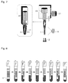
- Fig. 1 is a drawing showing an example of the outer appearance of the analyte testing automation system in the first embodiment of the present invention
- Fig. 2 is a drawing showing an overview of the configuration of the analyte testing automation system in the first embodiment of the present invention
- Fig. 3 is a drawing showing an example of the lifting operation parameters and the threshold parameters in accordance with the analyte container type which are recorded in the database of the analyte testing automation system in the first embodiment of the present invention
- Fig. 4 is a drawing showing an example of the overview of the analyte container to be checked by the analyte testing automation system in the first embodiment of the present invention
- Fig. 1 is a drawing showing an example of the outer appearance of the analyte testing automation system in the first embodiment of the present invention
- Fig. 2 is a drawing showing an overview of the configuration of the analyte testing automation system in the first embodiment of the present invention
- Fig. 3 is a drawing showing an example of the
- FIG. 5 is a drawing describing an overview of the differences in the threshold parameters in the analyte containers in the analyte testing automation system in the first embodiment of the present invention
- Fig. 6 is a drawing showing another example of the overview of the analyte container to be checked by the analyte testing automation system in the first embodiment of the present invention
- Fig. 7 is a drawing describing an overview of the analyte container lifting and rotating mechanisms in the first embodiment of the present invention
- Fig. 8 is a drawing showing the state of the rotation of the overview of the analyte container to be checked by the analyte testing automation system in the first embodiment of the present invention
- FIG. 9 is a drawing showing an example of the lifting of the analyte container for comparison
- Fig. 10 is a drawing showing an example of the lifting of the analyte container by the analyte testing automation system in the first embodiment of the present invention
- Fig. 11 is a flowchart of the control of the analyte testing automation system in the first embodiment of the present invention.
- the analyte testing automation system for checking the biological sample (analyte) housed in the blood collection tube 1 is constructed from an analyte pretreatment system 100 including a plurality of modules including an analyte loading unit 105, a centrifuge unit 106, an analyte checker 107, an opening unit 108, an aliquot sample test tube preparation unit 109, a dispensing part 110, a transfer unit 111, a plug part 102, an analyte storage unit 103, and an empty holder stocker part 104 as the basic elements, and an operation control unit 101 for controlling the entirety of the analyte pretreatment system 100.
- an analyte pretreatment system 100 including a plurality of modules including an analyte loading unit 105, a centrifuge unit 106, an analyte checker 107, an opening unit 108, an aliquot sample test tube preparation unit 109, a dispensing part 110, a transfer unit 111,
- An automatic analyzer 200 for performing the qualitative and quantitative analysis of the components in the analyte is connected at the end of the analyte pretreatment system 100.
- the analyte loading unit 105 is a module for loading a blood collection tube 1 in which an analyte is stored in the analyte pretreatment system 100.
- the centrifuge unit 106 is a module for centrifuging the loaded blood collection tube 1.
- the opening unit 108 is a module for opening the plug of the blood collection tube 1.
- the aliquot sample test tube preparation unit 109 is a module for performing the preparations necessary in order to dispense the loaded analyte in the dispensing part 110.
- the dispensing part 110 is a module for dispensing the centrifuged analyte so that it may be analyzed by an automatic analyzer 200, etc., and attaching a barcode, etc., to the dispensed container.
- the transfer unit 111 is a module for classifying the dispensed analyte container, and preparing to transfer to the automatic analyzer 200.
- the plug part 102 is a module for closing the plug in the container and the tube.
- the analyte storage unit 103 is a module for storing the closed container and tubes.
- the operation control unit 101 controls each module in the analyte pretreatment system 100 and the operation of each mechanism in each module.
- the analyte checker 107 includes the imaging unit 6 for analyte checking and a grip member 14.
- the imaging unit 6 for analyte checking and the grip member 14 are communicatively coupled to the operation control unit 101.
- analyte checker 107 is communicatively coupled to a first image processing unit 7a, a calculation unit 7b, a second image processing unit 7c, and a discrimination unit 7d provided in the operation control unit 101.
- the operation control unit 101 is further communicatively coupled to an imaging unit 3 for automatically verifying the blood collection tube provided in the analyte loading unit 105.
- the imaging unit 3 for automatically verifying the blood collection tube is a camera for capturing images of the blood collection tube 1 which was loaded in the analyte loading unit 105.
- the operation control unit 101 is communicatively coupled to a database 12 and a database 13. As shown in Fig. 3 , the various parameters 11 for each type of blood collection tube 1 such as the lifting operation parameter 11A and the threshold parameter 11B in accordance with the type of blood collection tube 1 are stored in advance in the database 12. The check result of the analyte in the blood collection tube 1 and all of the data used in the check are stored in the database 13.
- the various parameters 11 for each type of blood collection tube 1 are stored in a text-based table form, thus, visualization is possible and the correction and addition of parameters is easy. Further, the parameter 11 can be preset by the numerous device manufacturers in accordance with the type of blood collection tube 1 at the time the device is shipped, and thus, is already stored in the database 12.
- the first image processing unit 7a of the operation control unit 101 specifies the type of blood collection tube 1 by automatically verifying the type of blood collection tube by the outer appearance of the blood collection tube 1 and the color of the cap on the basis of the captured image in the imaging unit 3 for automatically verifying the blood collection tube.
- the specific method for example, is a method including a database obtained by photographing a container to be used in advance, and which performs matching with the captured image.
- the first image processing unit 7a transmits the obtained information to the operation control unit 101.
- the information of the diameter of the blood collection tube 1 is used when calculating the volume such as of the serum portion 1a in the discrimination unit 7d.
- the specification step for specifying the type of blood collection tube 1 is performed by the first image processing unit 7a and the imaging unit 3 for automatically verifying the blood collection tube.
- the calculation unit 7b of the operation control unit 101 determines the lifting operation parameter 11A most suitable for the type of blood collection tube 1 specified in the first image processing unit 7a from each of the lifting operation parameters 11A in accordance with the type of blood collection tube 1, among the various parameters 11 of each type of blood collection tube 1 stored in the database 12.
- the second image processing unit 7c processes the image captured by the imaging unit 6 for analyte checking according to the threshold parameter 11B in accordance with the type of blood collection tube 1 specified by the first image processing unit 7a.
- the discrimination unit 7d discriminates the state of the analyte in the blood collection tube 1 on the basis of the image processed by the second image processing unit 7c. Further, the discrimination unit 7d calculates the volume of the analyte in the blood collection tube 1 from the captured images in the imaging unit 6 for analyte checking.
- the blood collection tube 1 storing the sampled analyte when the blood collection tube 1 storing the sampled analyte is centrifuged, the contents are separated into a serum portion 1a, a separating agent 1b, and a blood clot portion 1c from top to bottom.
- the serum portion 1a has yellow colored components
- the separating agent 1b has white components
- the blood clot portion 1c has red colored components.
- a portion of the serum portion 1a is used in the analyte check.
- the second image processing unit 7c uses the threshold parameter which mainly includes the yellow colored components to extract the region of the serum portion 1a. Moreover, the discrimination unit 7d calculates the average value of the color of the region of the extracted serum portion, and compares the average value to the threshold parameter to perform discrimination of the hemolytic, the chylous, and the icteric states. Further, the discrimination unit 7d, after obtaining the upper surface 24 and the lower surface 25 (separating agent upper surface) of the serum portion 1a extracted by the second image processing unit 7c, calculates the volume of serum by the liquid height 27 which is the difference between the upper surface 24 and the lower surface 25 and the inner diameter 28 of the blood collection tube.
- the image captured in the second image processing unit 7c is converted to the HSV color system (hue, saturation, and value).
- the serum and the separating agent are in the HS region, and is distributed as the serum 121 of the normal analyte, the serum 121 of the hemolytic analyte, and the separating agent 123 as shown in Fig. 5 .
- the serum is distributed in the direction in which the saturation is low as the serum 131 of the normal analyte, the serum 132 of the hemolytic analyte, and the separating agent 133 as shown in Fig. 5 .
- the white color is emphasized, thus, when attempting to extract the serum region with the same threshold parameters (H, S and V values) as the transparent blood collection tube 1, verification of the interface between the serum portion 1a and the white gel-like separating agent 1b is difficult, thus, there are many cases when the extraction of the serum portion 1a is unsuccessful.
- the separating agent 1b there is a portion of the separating agent 1b in which the distribution of the separating agent 123 in the transparent blood collection tube 1 overlaps with the distribution of the serum 131 of the normal analyte in the milky-white blood collection tube 1, thus, the risk that the separation of the serum portion 1a from the separating agent 1b is unsuccessful is high. Further, the risk of incorrectly verifying that the state of the analyte (serum portion 1a) is a chylous state is high.
- the discrimination unit 7d captures an image of the outer appearance of the blood collection tube 1 in the imaging unit 3 for automatically verifying the blood collection tube in advance, and specifies the type of blood collection tube 1 in the first image processing unit 7a prior to the checking of the analyte check. Moreover, if a milky-white blood collection tube 1 is specified, the image processing is performed with reference to the threshold parameter 11B for the specified milky-white blood collection tube. With respect thereto, when a transparent blood collection tube 1 is specified, the image processing is performed with reference to the threshold parameter 11B for the specified transparent blood collection tube.
- the discrimination unit 7d after obtaining the upper surface 24 and the lower surface 25 (separating agent upper surface) of the serum portion 1a previously extracted by the second image processing unit 7c, seeks the liquid height 27 which is the difference between the upper surface 24 and the lower surface 25, and calculates the volume of the serum portion 1a of the blood collection tube 1 from the information relating to the height 27 of the obtained serum portion 1a and the information relating to the diameter of the blood collection tube 1 specified from the type of blood collection tube 1 specified by the first image processing unit 7a.
- the obtained information of the volume of the serum portion 1a is used in the dispensing part 110 when dispensing the sample into the blood collection tube 1.
- the grip member 14 lifts the blood collection tube 1 from the holder 2 according to the lifting operation parameter 11A obtained by the calculation unit 7b of the operation control unit 101.
- the grip member 14 grips the blood collection tube 1 by operating an opening and closing mechanism 23. After gripping the blood collection tube 1, the tube 1 is lifted to the imaging height position of the image in the imaging unit 6 for analyte checking by the blood collection tube lifting operation mechanism 21.
- a barcode label 4 is attached to the blood collection tube 1, thus, it is necessary to rotate the blood collection tube 1 so the gap of the barcode label 4 faces towards the imaging unit 6 side as shown in Fig. 8 , in order to perform the imaging by the imaging unit 6 for analyte checking. Therefore, after the blood collection tube 1 is lifted by the grip member 14, the grip member 14 is rotated by the blood collection tube rotation operation mechanism 22 to perform the rotation operation of the blood collection tube 1 while performing imaging by the imaging unit 6 for analyte checking.
- the blood collection tubes 1 loaded in the analyte testing automation system have different lengths. If the operation parameters for lifting all of the blood collection tubes are the same, it is necessary that the height position for grasping the blood collection tubes match with the gripping position 31 of short blood collection tubes. However, there is the problem that if the gripping height matches with the short blood collection tubes, when the long blood collection tubes are grasped by the grip member and the serum portion image is captured, an interference area 35 is produced as shown in Fig. 9 , and the grip member becomes impeded, thus, the verification of the interface is difficult.
- the lifting operation parameter 11B is appropriately changed according to the type of blood collection tube 1 when lifting the blood collection tube 1.
- the drop operation 33 to the height position and the elevation operation 34 to the blood collection tube imaging height position which grasps the blood collection tube 1 as shown in Fig. 10 and the lifting operation parameter 11A for the short blood collection tubes are used.
- a drop operation 37 to the height position and the elevation operation 38 to the blood collection tube imaging height position which grasps blood collection tube 1 as shown in Fig. 10 and the lifting operation parameter 11A for tall blood collection tubes are used.
- the imaging unit 6 for analyte checking captures an image from the side of the blood collection tube 1 in a state lifted by the grip member 14.
- Step S61 when it is verified in the operation control unit 101 by the user that the blood collection tube 1 has been loaded from the analyte loading unit 105 into the analyte pretreatment system 100 (Step S61), an image of the outer appearance of the blood collection tube 1 is captured in the imaging unit 3 for automatically verifying the blood collection tube in a state in which the blood collection tube 1 is placed in the holder 2 to specify the type of blood collection tube 1 from the image captured beforehand in the first image processing unit 7a of the operation control unit 101 (Step S62).
- the blood collection tube 1 is conveyed from the analyte loading unit 105 to the analyte checker 107 (Step S63).
- Step S64 the lifting operation parameter 11A is calculated (Step S64) in the calculation unit 7b on the basis of the automatic recognition result of the blood collection tube 1 in Step S62. Moreover, the blood collection tube 1 is lifted by the grip member 14 to the imaging height with reference to the lifting operation parameter 11A obtained by the calculation unit 7b in Step S64 (Step S65). Moreover, while the blood collection tube 1 is rotated by the blood collection tube rotation operation mechanism 22, images of the blood collection tube 1 are captured by the imaging unit 6 for analyte checking (Step S66).
- the threshold parameter 11B is obtained from each of the parameters of database 12 on the basis of the automatic recognition result of the blood collection tube 1 in Step S62 (Step S67). Note that, Step S67 may be performed at any time after Step S62 until the next Step S68 starts.
- Step S67 using the threshold parameter 11B obtained in Step S67, the region of the serum portion 1a is extracted from the image captured by the imaging unit 6 for analyte checking in Step S66 in the second image processing unit 7c (Step S68).
- Step S69 the volume of serum is calculated in the discrimination unit 7d from the extraction result in Step S68 (Step S69). Further, with reference to the threshold parameter 11B, the analyte in the blood collection tube 1 is compared with the average value of the color of the serum, and whether the analyte in the blood collection tube 1 is any of the hemolytic, the chylous, or the icteric state is discriminated in the discrimination unit 7d (Step S70).
- Step S70 the discrimination unit 7d confirms whether or not there is an abnormality in the shape of the analyte or the liquid quantity, and when there is an abnormality, instructions such as a redrawing of blood are displayed on the display unit of the operation control unit 101, and if there is no abnormality, the process proceeds to Step S71.
- Step S70 The image processing (analyte check) result in Step S70 and the image captured in Step S66 are stored in the analyte check result storage database 13 (Step S71).
- Step S70 If instructions such as for a redrawing of blood are received in Step S70, the user is able to take early measures by making arrangements so that a redrawing of blood may be performed.
- the first embodiment of the analyte testing automation system and the biological sample check method of the present invention automatically recognizes the type of blood collection tube 1 loaded into the system, switches the image processing threshold on the basis of this automatic recognition result, uses the threshold parameter in accordance with the blood collection tube type to perform image processing, and performs checking of the state and volume of the analyte.
- the transparent blood collection tube 1 was mixed with the milky cloudy blood collection tube 1, it is possible to perform image processing according to the type of blood collection tube 1, thus, the region extraction of the serum portion and the precision of the state determination of the analyte can increase. Further, the degree to which the analysis of the analyte can be performed in the automatic analyzer 200 can be discriminated, controlled so as to prioritize testing of analysis items having a higher priority, and it is possible for the user to know that the redrawing of blood is necessary by the occurrence of insufficiencies, thus, rapid and flexible testing is possible even if loaded into a system without consideration of the type of blood collection tube 1.
- analyte checking such as the verification of the volume of serum and the state of the analyte can be automatically and precisely performed by only setting the blood collection tube 1 in the loading position without consideration of the differences in color from the transparent blood collection tube 1 as shown in Fig. 4 to the clouded milky-white as shown in Fig. 6 , and the differences in the shape of the blood collection tube 1 such as the length of the tube and the inner diameter of the tube as shown in Fig. 9 and Fig. 10 , and the blood collection tube 1 can be loaded in the analyte testing automation system without it being necessary for the user to perform operations which require time and effort such as calibration.
- the blood collection tube can be grasped and lifted to a suitable height by switching the lifting operation for checking the state and volume of analyte on the basis of the automatic recognition result, determining the mechanical operation parameter in accordance with the blood collection tube type, and lifting by grasping the blood collection tube 1, thus, it is possible that the grip member 14 does not cause interference in the imaging area when capturing an image, and it is possible to control the interference due to the holder 2 by lifting, thus, disturbances when checking the state can be minimized and an improvement of the check information can be ensured.
- parameter 11 is set in advance in accordance with all of the types of blood collection tubes 1 at the time the device is shipped, and thus, is an advantageous point in that it is not necessary for the user to perform calibration by the parameters already stored in the database 12.
- the database 12 and the database 13 exist within the operation control unit 101. Further, these databases 12 and 13 may exist in a server through a network.
- the first image processing unit 7a, the calculation unit 7b, the second image processing unit 7c, and the discrimination unit 7d are present within the operation control unit 101, and the above features may exist within the analyte checker 107, or may exist elsewhere, and the imaging unit 3 for automatically verifying the blood collection tube and the imaging unit 6 for analyte checking, the operation control unit 101, and the grip member 14 may be communicatively connected.
- the type of blood collection tube was automatically verified by the shape of the blood collection tube 1, the color of the cap on the basis of the captured image, and the methods to be specified were explained, but the method for specifying the type of blood collection tube is not limited thereto.
- the type of blood collection tube may be specified by detecting feature points on the outer appearance of the blood collection tube 1 with a single, or, a plurality of beam sensors, a reflection type sensor, and the like, and the color of the cap may even be verified by the change of the optical reflectance.
- the information relating to the type of blood collection tube may be recorded in a storage medium such as a barcode label or an RFID tag provided on the analyte container or the holder, and may be stored in a device side storage unit in association with the verification information stored in the barcode or the RFID tag.
- a storage medium such as a barcode label or an RFID tag provided on the analyte container or the holder
- the discrimination process of the serum portion 1a in the discrimination unit 7d has been explained regarding the case when there are two types of blood collection tubes 1, a transparent tube and a milky-white tube, but the type of blood collection tube 1 is not limited thereto, and even in the cases of other colors and other materials, by seeking the threshold parameter 11B in accordance with each color and material on the device maker's side and storing in database 12 in advance, there is the possibility that the tube corresponds to various types of blood collection tubes 1.
- the parameters 11 set for each type of blood collection tube are not limited to the lifting operation parameter 11A and the threshold parameter 11B.
- Parameters may be used in the prevention of the loss of interface recognition due to the similarity of the colors of the chylous analyte and the separating agent by registering information such as the presence of a separating agent and the presence of a label, and may be used in threshold correction when the color of the serum appears to be dark due to the influence of the label. Further, the parameters may be used in the judgment of whether or not the filling quantity in the blood collection tubes is sufficient by registering the information of the graduation markings on the container itself.
- FIG. 12 A second embodiment of the analyte testing automation system and the biological sample check method of the present invention will be explained using Fig. 12 .
- the analyte testing automation system in the second embodiment is the same as the analyte testing automation system of the first embodiment, with the exception that the imaging unit 6 for analyte checking also serves as the imaging unit 3 for automatically verifying the blood collection tube for which images of the blood collection tube 1 loaded in the analyte testing automation system were captured, thus, the details have been omitted.
- Fig. 12 is a drawing showing the overview of the configuration of the analyte testing automation system in the second embodiment of the present invention.
- the analyte testing automation system of the second embodiment does not provide an imaging unit 3 for automatically verifying the blood collection tube in the analyte loading unit 105, and the imaging unit 6 for analyte checking provided in the analyte checker 107 is a configuration which also serves as the imaging unit 3 for automatically verifying the blood collection tube which captures an image of the blood collection tube 1 loaded within the analyte pretreatment system 100.
- the blood collection tube 1 when the blood collection tube 1 is loaded in the analyte loading unit 105, if the blood collection tube 1 was placed in the holder 2, it is conveyed to the analyte checker 107, an image of the blood collection tube 1 is captured by the imaging unit 6 for analyte checking in a state in which it was placed in the holder 2 prior to the lifting operation by the grip member 14, and the type of blood collection tube 1 is automatically verified by the first image processing unit 7a and the calculation unit 7b.
- the lifting parameter 11A is obtained in accordance with the blood collection tube 1 using this result and the threshold parameter 11B of the image processing is obtained. Then, the lifting process of the blood collection tube 1 is performed by the grip member 14, and the subsequent processes are the same as in the first embodiment.
- the second embodiment of the analyte testing automation system and the biological sample check method of the present invention can obtain almost the same effect as with the first embodiment of the analyte testing automation system and the biological sample check method.
- the imaging unit for analyte checking is used in the external appearance recognition of the blood collection tubes without providing an exclusive imaging unit, thus, the image capturing mechanism can be reduced and the miniaturization and price reduction of the device is possible.
- the state and the volume of the sample in the blood collection tubes may be grasped by the analyte checker itself, and thus, the analyte checker is a module suitable for adding to an existing analyte pretreatment system.
- FIG. 13 A third embodiment of the analyte testing automation system, the biological sample check module, and the biological sample check method of the present invention will be explained using Fig. 13 .
- the analyte testing automation system in the third embodiment is the same as the analyte testing automation system of the first embodiment, with the exception that the imaging unit 3 for automatically verifying the blood collection tube was provided in the analyte checker, thus, the details have been omitted.
- Fig. 13 is a drawing showing the overview of the configuration of the analyte testing automation system in the third embodiment of the present invention.
- the imaging unit 3 for automatically verifying the blood collection tube which are loaded in the analyte loading unit 105 and which captures images of the blood collection tube 1 which are loaded in the analyte checker 107 is provided on the inlet side in the analyte checker 107 of the blood collection tube 1 which is conveyed to the analyte checker 107.
- the third embodiment of the analyte testing automation system, the biological sample check module, and the biological sample check method of the present invention can obtain almost the same effect as with the first embodiment of the analyte testing automation system, the biological sample check module, and the biological sample check method.
- the biological sample check module is a module suitable for adding to an existing analyte pretreatment system.
- the abovementioned analyte checker and volume checking module for realizing an analyte check function prevents the wasteful loss of consumables such as the analyte and dispensing chips, and thus, are desirably provided between the centrifuge unit 106 and the dispensing part 110.
Landscapes
- Health & Medical Sciences (AREA)
- Life Sciences & Earth Sciences (AREA)
- Chemical & Material Sciences (AREA)
- Engineering & Computer Science (AREA)
- Physics & Mathematics (AREA)
- Biomedical Technology (AREA)
- Pathology (AREA)
- Analytical Chemistry (AREA)
- General Physics & Mathematics (AREA)
- Immunology (AREA)
- Biochemistry (AREA)
- General Health & Medical Sciences (AREA)
- Hematology (AREA)
- Ecology (AREA)
- Dispersion Chemistry (AREA)
- Biophysics (AREA)
- Molecular Biology (AREA)
- Urology & Nephrology (AREA)
- Food Science & Technology (AREA)
- Medicinal Chemistry (AREA)
- Automatic Analysis And Handling Materials Therefor (AREA)
- Investigating Or Analysing Biological Materials (AREA)
Abstract
Description
- The present invention relates to an analyte testing automation system, a biological sample check module, and a biological sample check method for automatically checking the state and volume of an analyte which can be used in the analyte testing automation system for clinical laboratory tests.
- For example,
Patent Literature 1 discloses the technology for capturing the image of a blood collection tube with a camera, comparing the captured image of the blood collection tube with a black and white color calibration result to distinguish the type of analyte container by a matching process, and calculating the liquid volume after determining the bias value as the technology for realizing an analyte check function. - Patent Literature 1:
WO1999-28724 - Recently, the integration of an analyte check function in which the volume of serum obtained by centrifuging the analyte being used and the state of the analyte after centrifugation are automatically verified in an analyte testing automation system which performs pretreatments such as dispensing to perform biochemical analyses or immunoassays of analytes such as blood and urine has been sought in the field of clinical laboratory examinations.
- Regarding the state of the analyte after centrifugation, other than the normal state, the analyte may be in a hemolytic state, a chylous state, or an icteric state. An analyte in an abnormal state cannot be used in analysis, thus, redrawing is necessary, and accordingly, it is necessary to discriminate an analyte which is in an abnormal state.
- Conventionally, analyte checking operations such as the verification of the serum volume and the discrimination of abnormal analytes was performed visually by a laboratory technician, thus, the efficiency was poor. Therefore, the automation of the checking operation has been desired, and the integration of the analyte check function in a pretreatment system has been sought.
- There are numerous types of blood collection tubes which are used in analyte testing automation systems. For example, not only are there differences in the shape such as the length of the tube and the inner diameter of the tube, but there are also differences in the materials such as plastic or vinyl, thus, there are colored and transparent tubes and milky-white clouded tubes (white translucent).
- More specifically, in the case of a milky-white blood collection tube, the contents of the blood collection tubes can be observed from the outside through the wall, but with respect to the color of the serum portion of the result from the image captured by a camera, the white color is emphasized compared to transparent blood collection tubes, thus, the risk for incorrectly verifying the state of the analyte was high. Further, the verification of the interface between the serum and the white gel-like separating agent is difficult, thus, the risk of incorrectly verifying the volume of serum was high.
- Taking the aforementioned problems into consideration,
Patent Literature 1 specifies a method for calibrating each of the blood collection tubes to be used, setting the presence of a gel-like separating agent, and automatically verifying a blood collection tube, but the information of the color of the blood collection tube itself has not been managed, thus, the problem regarding an incorrect verification in the same manner as stated above cannot be averted. - Further, the method of
Patent Literature 1 requires that the calibration of each of the blood collection tubes to be used be performed by the user, thus, there is the problem that calibration requires much time and effort. - An object of the present invention is to provide an analyte testing automation system, a biological sample check module, and a biological sample check method which can precisely and automatically check the state and volume of an analyte even if numerous types of blood collection tubes are used.
- The configurations described in, for example, the claims are used to solve the aforementioned problems.
- The present invention includes a plurality of means for solving the aforementioned problems, and one example is an imaging unit for capturing an image from the side of a container containing a biological sample, a container type specification unit for obtaining information specifying the type of container, and a control unit having a processing unit for processing an image captured by the imaging unit on the basis of the parameters in accordance with the container type specified by the container type specification unit and a discrimination unit for discriminating the state of the contents within the container on the basis of the processing by the processing unit. Advantageous Effects of Invention
- According to the present invention, the user can automatically and precisely perform the checking of the state and volume of the analyte by only setting numerous types of blood collection tubes in the loading position without considering the differences in color such as from a transparent tube to a milky-white clouded tube and the different shapes of blood collection tubes such as the length of the tune and the inner diameter of the tube, and the user can load the blood collection tubes in the analyte testing automation system without the necessity of performing operations which require time and effort such as calibration.
-
-
Fig. 1 is a drawing showing an example of the outer appearance of the analyte testing automation system in a first embodiment of the present invention. -
Fig. 2 is a drawing showing an overview of the configuration of the analyte testing automation system in the first embodiment of the present invention. -
Fig. 3 is a drawing showing an example of the lifting operation parameters and the threshold parameters in accordance with the analyte container type which are recorded in the database of the analyte testing automation system in the first embodiment of the present invention. -
Fig. 4 is a drawing showing an example of the overview of the analyte container to be checked by the analyte testing automation system in the first embodiment of the present invention. -
Fig. 5 is a drawing describing an overview of the differences in the threshold parameters in the analyte containers in the analyte testing automation system in the first embodiment of the present invention. -
Fig. 6 is a drawing showing another example of the overview of the analyte container to be checked by the analyte testing automation system in the first embodiment of the present invention. -
Fig. 7 is a drawing describing an overview of the analyte container lifting and rotating mechanisms in the first embodiment of the present invention. -
Fig. 8 is a drawing showing the state of the rotation of the overview of the analyte container to be checked by the analyte testing automation system in the first embodiment of the present invention. -
Fig. 9 is a drawing showing an example of the lifting of the analyte container for comparison. -
Fig. 10 is a drawing showing an example of the lifting of the analyte container by the analyte testing automation system in the first embodiment of the present invention. -
Fig. 11 is a flowchart of the control of the analyte testing automation system in the first embodiment of the present invention. -
Fig. 12 is a drawing showing the overview of the configuration of the analyte testing automation system in a second embodiment of the present invention. -
Fig. 13 is a drawing showing the overview of the configuration of the analyte testing automation system in a third embodiment of the present invention. - The embodiments of the analyte testing automation system, the biological sample check module, and the biological sample check method of the present invention will be explained below using the drawings.
- A first embodiment of the analyte testing automation system and the biological sample check method of the present invention will be explained using
Figs. 1 to 11 . -
Fig. 1 is a drawing showing an example of the outer appearance of the analyte testing automation system in the first embodiment of the present invention,Fig. 2 is a drawing showing an overview of the configuration of the analyte testing automation system in the first embodiment of the present invention,Fig. 3 is a drawing showing an example of the lifting operation parameters and the threshold parameters in accordance with the analyte container type which are recorded in the database of the analyte testing automation system in the first embodiment of the present invention,Fig. 4 is a drawing showing an example of the overview of the analyte container to be checked by the analyte testing automation system in the first embodiment of the present invention,Fig. 5 is a drawing describing an overview of the differences in the threshold parameters in the analyte containers in the analyte testing automation system in the first embodiment of the present invention,Fig. 6 is a drawing showing another example of the overview of the analyte container to be checked by the analyte testing automation system in the first embodiment of the present invention,Fig. 7 is a drawing describing an overview of the analyte container lifting and rotating mechanisms in the first embodiment of the present invention,Fig. 8 is a drawing showing the state of the rotation of the overview of the analyte container to be checked by the analyte testing automation system in the first embodiment of the present invention,Fig. 9 is a drawing showing an example of the lifting of the analyte container for comparison,Fig. 10 is a drawing showing an example of the lifting of the analyte container by the analyte testing automation system in the first embodiment of the present invention, andFig. 11 is a flowchart of the control of the analyte testing automation system in the first embodiment of the present invention. - In
Fig. 1 , the analyte testing automation system for checking the biological sample (analyte) housed in theblood collection tube 1 is constructed from ananalyte pretreatment system 100 including a plurality of modules including ananalyte loading unit 105, acentrifuge unit 106, ananalyte checker 107, anopening unit 108, an aliquot sample testtube preparation unit 109, a dispensingpart 110, atransfer unit 111, aplug part 102, ananalyte storage unit 103, and an emptyholder stocker part 104 as the basic elements, and anoperation control unit 101 for controlling the entirety of theanalyte pretreatment system 100. - An
automatic analyzer 200 for performing the qualitative and quantitative analysis of the components in the analyte is connected at the end of theanalyte pretreatment system 100. - The
analyte loading unit 105 is a module for loading ablood collection tube 1 in which an analyte is stored in theanalyte pretreatment system 100. Thecentrifuge unit 106 is a module for centrifuging the loadedblood collection tube 1. Theopening unit 108 is a module for opening the plug of theblood collection tube 1. The aliquot sample testtube preparation unit 109 is a module for performing the preparations necessary in order to dispense the loaded analyte in the dispensingpart 110. The dispensingpart 110 is a module for dispensing the centrifuged analyte so that it may be analyzed by anautomatic analyzer 200, etc., and attaching a barcode, etc., to the dispensed container. Thetransfer unit 111 is a module for classifying the dispensed analyte container, and preparing to transfer to theautomatic analyzer 200. Theplug part 102 is a module for closing the plug in the container and the tube. Theanalyte storage unit 103 is a module for storing the closed container and tubes. Theoperation control unit 101 controls each module in theanalyte pretreatment system 100 and the operation of each mechanism in each module. - Next, the
analyte checker 107 and the configurations related to theanalyte checker 107 in the analyte testing automation system of the embodiment will be explained with reference toFig. 2 . - In
Fig. 2 , theanalyte checker 107 includes theimaging unit 6 for analyte checking and agrip member 14. Theimaging unit 6 for analyte checking and thegrip member 14 are communicatively coupled to theoperation control unit 101. - Further, the
analyte checker 107 is communicatively coupled to a firstimage processing unit 7a, acalculation unit 7b, a secondimage processing unit 7c, and adiscrimination unit 7d provided in theoperation control unit 101. Theoperation control unit 101 is further communicatively coupled to animaging unit 3 for automatically verifying the blood collection tube provided in theanalyte loading unit 105. - The
imaging unit 3 for automatically verifying the blood collection tube is a camera for capturing images of theblood collection tube 1 which was loaded in theanalyte loading unit 105. - The
operation control unit 101 is communicatively coupled to adatabase 12 and adatabase 13. As shown inFig. 3 , thevarious parameters 11 for each type ofblood collection tube 1 such as thelifting operation parameter 11A and thethreshold parameter 11B in accordance with the type ofblood collection tube 1 are stored in advance in thedatabase 12. The check result of the analyte in theblood collection tube 1 and all of the data used in the check are stored in thedatabase 13. - As shown in
Fig. 3 , thevarious parameters 11 for each type ofblood collection tube 1 are stored in a text-based table form, thus, visualization is possible and the correction and addition of parameters is easy. Further, theparameter 11 can be preset by the numerous device manufacturers in accordance with the type ofblood collection tube 1 at the time the device is shipped, and thus, is already stored in thedatabase 12. - Returning to
Fig. 2 , the firstimage processing unit 7a of theoperation control unit 101 specifies the type ofblood collection tube 1 by automatically verifying the type of blood collection tube by the outer appearance of theblood collection tube 1 and the color of the cap on the basis of the captured image in theimaging unit 3 for automatically verifying the blood collection tube. The specific method, for example, is a method including a database obtained by photographing a container to be used in advance, and which performs matching with the captured image. - The first
image processing unit 7a transmits the obtained information to theoperation control unit 101. The information of the diameter of theblood collection tube 1 is used when calculating the volume such as of the serum portion 1a in thediscrimination unit 7d. - The specification step for specifying the type of
blood collection tube 1 is performed by the firstimage processing unit 7a and theimaging unit 3 for automatically verifying the blood collection tube. - The
calculation unit 7b of theoperation control unit 101 determines thelifting operation parameter 11A most suitable for the type ofblood collection tube 1 specified in the firstimage processing unit 7a from each of the liftingoperation parameters 11A in accordance with the type ofblood collection tube 1, among thevarious parameters 11 of each type ofblood collection tube 1 stored in thedatabase 12. - The second
image processing unit 7c processes the image captured by theimaging unit 6 for analyte checking according to thethreshold parameter 11B in accordance with the type ofblood collection tube 1 specified by the firstimage processing unit 7a. - The
discrimination unit 7d discriminates the state of the analyte in theblood collection tube 1 on the basis of the image processed by the secondimage processing unit 7c. Further, thediscrimination unit 7d calculates the volume of the analyte in theblood collection tube 1 from the captured images in theimaging unit 6 for analyte checking. - The details of the analyte checking in the
blood collection tube 1 will be explained with reference toFig. 4 . - As shown in
Fig. 4 , when theblood collection tube 1 storing the sampled analyte is centrifuged, the contents are separated into a serum portion 1a, a separatingagent 1b, and ablood clot portion 1c from top to bottom. The serum portion 1a has yellow colored components, the separatingagent 1b has white components, and theblood clot portion 1c has red colored components. Among them, a portion of the serum portion 1a is used in the analyte check. - Therefore, the second
image processing unit 7c uses the threshold parameter which mainly includes the yellow colored components to extract the region of the serum portion 1a. Moreover, thediscrimination unit 7d calculates the average value of the color of the region of the extracted serum portion, and compares the average value to the threshold parameter to perform discrimination of the hemolytic, the chylous, and the icteric states. Further, thediscrimination unit 7d, after obtaining theupper surface 24 and the lower surface 25 (separating agent upper surface) of the serum portion 1a extracted by the secondimage processing unit 7c, calculates the volume of serum by theliquid height 27 which is the difference between theupper surface 24 and thelower surface 25 and theinner diameter 28 of the blood collection tube. - The details of the discrimination process of the state of the analyte in the
discrimination unit 7d will be explained below inFig. 5 . - In order for the
discrimination unit 7d to discriminate the state of the analyte (serum portion 1a), the image captured in the secondimage processing unit 7c is converted to the HSV color system (hue, saturation, and value). - When the
blood collection tube 1 is transparent, the serum and the separating agent are in the HS region, and is distributed as theserum 121 of the normal analyte, theserum 121 of the hemolytic analyte, and the separatingagent 123 as shown inFig. 5 . However, in the case of the milky-white blood collection tube 1 (white translucent blood collection tube) as shown inFig. 6 , the serum is distributed in the direction in which the saturation is low as theserum 131 of the normal analyte, theserum 132 of the hemolytic analyte, and the separatingagent 133 as shown inFig. 5 . Therefore, in the case of the milky-whiteblood collection tube 1, the white color is emphasized, thus, when attempting to extract the serum region with the same threshold parameters (H, S and V values) as the transparentblood collection tube 1, verification of the interface between the serum portion 1a and the white gel-like separating agent 1b is difficult, thus, there are many cases when the extraction of the serum portion 1a is unsuccessful. Specifically, there is a portion of the separatingagent 1b in which the distribution of the separatingagent 123 in the transparentblood collection tube 1 overlaps with the distribution of theserum 131 of the normal analyte in the milky-whiteblood collection tube 1, thus, the risk that the separation of the serum portion 1a from the separatingagent 1b is unsuccessful is high. Further, the risk of incorrectly verifying that the state of the analyte (serum portion 1a) is a chylous state is high. - Therefore, the
discrimination unit 7d captures an image of the outer appearance of theblood collection tube 1 in theimaging unit 3 for automatically verifying the blood collection tube in advance, and specifies the type ofblood collection tube 1 in the firstimage processing unit 7a prior to the checking of the analyte check. Moreover, if a milky-whiteblood collection tube 1 is specified, the image processing is performed with reference to thethreshold parameter 11B for the specified milky-white blood collection tube. With respect thereto, when a transparentblood collection tube 1 is specified, the image processing is performed with reference to thethreshold parameter 11B for the specified transparent blood collection tube. - Next, the calculation method of the volume of the analyte in the
blood collection tube 1 will be explained. - The
discrimination unit 7d, after obtaining theupper surface 24 and the lower surface 25 (separating agent upper surface) of the serum portion 1a previously extracted by the secondimage processing unit 7c, seeks theliquid height 27 which is the difference between theupper surface 24 and thelower surface 25, and calculates the volume of the serum portion 1a of theblood collection tube 1 from the information relating to theheight 27 of the obtained serum portion 1a and the information relating to the diameter of theblood collection tube 1 specified from the type ofblood collection tube 1 specified by the firstimage processing unit 7a. - The obtained information of the volume of the serum portion 1a is used in the dispensing
part 110 when dispensing the sample into theblood collection tube 1. - Returning to
Fig. 2 , thegrip member 14 lifts theblood collection tube 1 from theholder 2 according to thelifting operation parameter 11A obtained by thecalculation unit 7b of theoperation control unit 101. - The details of the lifting and the accompanying rotation of the
blood collection tube 1 in thegrip member 14 will be explained below with reference toFig. 7 . - As shown in
Fig. 7 , thegrip member 14 grips theblood collection tube 1 by operating an opening andclosing mechanism 23. After gripping theblood collection tube 1, thetube 1 is lifted to the imaging height position of the image in theimaging unit 6 for analyte checking by the blood collection tube liftingoperation mechanism 21. - A
barcode label 4 is attached to theblood collection tube 1, thus, it is necessary to rotate theblood collection tube 1 so the gap of thebarcode label 4 faces towards theimaging unit 6 side as shown inFig. 8 , in order to perform the imaging by theimaging unit 6 for analyte checking. Therefore, after theblood collection tube 1 is lifted by thegrip member 14, thegrip member 14 is rotated by the blood collection tuberotation operation mechanism 22 to perform the rotation operation of theblood collection tube 1 while performing imaging by theimaging unit 6 for analyte checking. - The
blood collection tubes 1 loaded in the analyte testing automation system have different lengths. If the operation parameters for lifting all of the blood collection tubes are the same, it is necessary that the height position for grasping the blood collection tubes match with thegripping position 31 of short blood collection tubes. However, there is the problem that if the gripping height matches with the short blood collection tubes, when the long blood collection tubes are grasped by the grip member and the serum portion image is captured, aninterference area 35 is produced as shown inFig. 9 , and the grip member becomes impeded, thus, the verification of the interface is difficult. - Therefore, in the embodiment, the lifting
operation parameter 11B is appropriately changed according to the type ofblood collection tube 1 when lifting theblood collection tube 1. - Specifically, when it is specified that the short
blood collection tube 1 in which the outer appearance of theblood collection tube 1 was captured beforehand in theimaging unit 3 for automatically verifying the blood collection tube, and the type ofblood collection tube 1 specified in the firstimage processing unit 7a is being used, thedrop operation 33 to the height position and theelevation operation 34 to the blood collection tube imaging height position which grasps theblood collection tube 1 as shown inFig. 10 and thelifting operation parameter 11A for the short blood collection tubes are used. Further, when it is specified that a longblood collection tube 1 is being used, adrop operation 37 to the height position and theelevation operation 38 to the blood collection tube imaging height position which graspsblood collection tube 1 as shown inFig. 10 and thelifting operation parameter 11A for tall blood collection tubes are used. - Returning to
Fig. 2 , theimaging unit 6 for analyte checking captures an image from the side of theblood collection tube 1 in a state lifted by thegrip member 14. - Next, the sequence of the processes of the operation of the analyte testing automation system of the embodiment will be explained below with reference to
Fig. 11 . - First, when it is verified in the
operation control unit 101 by the user that theblood collection tube 1 has been loaded from theanalyte loading unit 105 into the analyte pretreatment system 100 (Step S61), an image of the outer appearance of theblood collection tube 1 is captured in theimaging unit 3 for automatically verifying the blood collection tube in a state in which theblood collection tube 1 is placed in theholder 2 to specify the type ofblood collection tube 1 from the image captured beforehand in the firstimage processing unit 7a of the operation control unit 101 (Step S62). - Then, the
blood collection tube 1 is conveyed from theanalyte loading unit 105 to the analyte checker 107 (Step S63). - While the
blood collection tube 1 is being conveyed to theanalyte checker 107, the liftingoperation parameter 11A is calculated (Step S64) in thecalculation unit 7b on the basis of the automatic recognition result of theblood collection tube 1 in Step S62. Moreover, theblood collection tube 1 is lifted by thegrip member 14 to the imaging height with reference to thelifting operation parameter 11A obtained by thecalculation unit 7b in Step S64 (Step S65). Moreover, while theblood collection tube 1 is rotated by the blood collection tuberotation operation mechanism 22, images of theblood collection tube 1 are captured by theimaging unit 6 for analyte checking (Step S66). - Further, the
threshold parameter 11B is obtained from each of the parameters ofdatabase 12 on the basis of the automatic recognition result of theblood collection tube 1 in Step S62 (Step S67). Note that, Step S67 may be performed at any time after Step S62 until the next Step S68 starts. - Next, using the
threshold parameter 11B obtained in Step S67, the region of the serum portion 1a is extracted from the image captured by theimaging unit 6 for analyte checking in Step S66 in the secondimage processing unit 7c (Step S68). - Next, the volume of serum is calculated in the
discrimination unit 7d from the extraction result in Step S68 (Step S69). Further, with reference to thethreshold parameter 11B, the analyte in theblood collection tube 1 is compared with the average value of the color of the serum, and whether the analyte in theblood collection tube 1 is any of the hemolytic, the chylous, or the icteric state is discriminated in thediscrimination unit 7d (Step S70). In Step S70, thediscrimination unit 7d confirms whether or not there is an abnormality in the shape of the analyte or the liquid quantity, and when there is an abnormality, instructions such as a redrawing of blood are displayed on the display unit of theoperation control unit 101, and if there is no abnormality, the process proceeds to Step S71. - The image processing (analyte check) result in Step S70 and the image captured in Step S66 are stored in the analyte check result storage database 13 (Step S71).
- If instructions such as for a redrawing of blood are received in Step S70, the user is able to take early measures by making arrangements so that a redrawing of blood may be performed.
- As stated above, the first embodiment of the analyte testing automation system and the biological sample check method of the present invention automatically recognizes the type of
blood collection tube 1 loaded into the system, switches the image processing threshold on the basis of this automatic recognition result, uses the threshold parameter in accordance with the blood collection tube type to perform image processing, and performs checking of the state and volume of the analyte. - By these processes, even when the transparent
blood collection tube 1 was mixed with the milky cloudyblood collection tube 1, it is possible to perform image processing according to the type ofblood collection tube 1, thus, the region extraction of the serum portion and the precision of the state determination of the analyte can increase. Further, the degree to which the analysis of the analyte can be performed in theautomatic analyzer 200 can be discriminated, controlled so as to prioritize testing of analysis items having a higher priority, and it is possible for the user to know that the redrawing of blood is necessary by the occurrence of insufficiencies, thus, rapid and flexible testing is possible even if loaded into a system without consideration of the type ofblood collection tube 1. - Therefore, even if the user performs calibration to each type of
blood collection tube 1 to be used, analyte checking such as the verification of the volume of serum and the state of the analyte can be automatically and precisely performed by only setting theblood collection tube 1 in the loading position without consideration of the differences in color from the transparentblood collection tube 1 as shown inFig. 4 to the clouded milky-white as shown inFig. 6 , and the differences in the shape of theblood collection tube 1 such as the length of the tube and the inner diameter of the tube as shown inFig. 9 and Fig. 10 , and theblood collection tube 1 can be loaded in the analyte testing automation system without it being necessary for the user to perform operations which require time and effort such as calibration. - Further, the blood collection tube can be grasped and lifted to a suitable height by switching the lifting operation for checking the state and volume of analyte on the basis of the automatic recognition result, determining the mechanical operation parameter in accordance with the blood collection tube type, and lifting by grasping the
blood collection tube 1, thus, it is possible that thegrip member 14 does not cause interference in the imaging area when capturing an image, and it is possible to control the interference due to theholder 2 by lifting, thus, disturbances when checking the state can be minimized and an improvement of the check information can be ensured. - Further,
parameter 11 is set in advance in accordance with all of the types ofblood collection tubes 1 at the time the device is shipped, and thus, is an advantageous point in that it is not necessary for the user to perform calibration by the parameters already stored in thedatabase 12. - Note that, it is possible that the
database 12 and thedatabase 13 exist within theoperation control unit 101. Further, thesedatabases - Further, it is not always necessary that the first
image processing unit 7a, thecalculation unit 7b, the secondimage processing unit 7c, and thediscrimination unit 7d are present within theoperation control unit 101, and the above features may exist within theanalyte checker 107, or may exist elsewhere, and theimaging unit 3 for automatically verifying the blood collection tube and theimaging unit 6 for analyte checking, theoperation control unit 101, and thegrip member 14 may be communicatively connected. - In the abovementioned embodiment, the type of blood collection tube was automatically verified by the shape of the
blood collection tube 1, the color of the cap on the basis of the captured image, and the methods to be specified were explained, but the method for specifying the type of blood collection tube is not limited thereto. For example, the type of blood collection tube may be specified by detecting feature points on the outer appearance of theblood collection tube 1 with a single, or, a plurality of beam sensors, a reflection type sensor, and the like, and the color of the cap may even be verified by the change of the optical reflectance. Further, the information relating to the type of blood collection tube may be recorded in a storage medium such as a barcode label or an RFID tag provided on the analyte container or the holder, and may be stored in a device side storage unit in association with the verification information stored in the barcode or the RFID tag. - Further, the discrimination process of the serum portion 1a in the
discrimination unit 7d has been explained regarding the case when there are two types ofblood collection tubes 1, a transparent tube and a milky-white tube, but the type ofblood collection tube 1 is not limited thereto, and even in the cases of other colors and other materials, by seeking thethreshold parameter 11B in accordance with each color and material on the device maker's side and storing indatabase 12 in advance, there is the possibility that the tube corresponds to various types ofblood collection tubes 1. - The
parameters 11 set for each type of blood collection tube are not limited to thelifting operation parameter 11A and thethreshold parameter 11B. Parameters may be used in the prevention of the loss of interface recognition due to the similarity of the colors of the chylous analyte and the separating agent by registering information such as the presence of a separating agent and the presence of a label, and may be used in threshold correction when the color of the serum appears to be dark due to the influence of the label. Further, the parameters may be used in the judgment of whether or not the filling quantity in the blood collection tubes is sufficient by registering the information of the graduation markings on the container itself. - A second embodiment of the analyte testing automation system and the biological sample check method of the present invention will be explained using
Fig. 12 . - The analyte testing automation system in the second embodiment is the same as the analyte testing automation system of the first embodiment, with the exception that the
imaging unit 6 for analyte checking also serves as theimaging unit 3 for automatically verifying the blood collection tube for which images of theblood collection tube 1 loaded in the analyte testing automation system were captured, thus, the details have been omitted. -
Fig. 12 is a drawing showing the overview of the configuration of the analyte testing automation system in the second embodiment of the present invention. - As shown in
Fig. 12 , the analyte testing automation system of the second embodiment does not provide animaging unit 3 for automatically verifying the blood collection tube in theanalyte loading unit 105, and theimaging unit 6 for analyte checking provided in theanalyte checker 107 is a configuration which also serves as theimaging unit 3 for automatically verifying the blood collection tube which captures an image of theblood collection tube 1 loaded within theanalyte pretreatment system 100. - In the embodiment, when the
blood collection tube 1 is loaded in theanalyte loading unit 105, if theblood collection tube 1 was placed in theholder 2, it is conveyed to theanalyte checker 107, an image of theblood collection tube 1 is captured by theimaging unit 6 for analyte checking in a state in which it was placed in theholder 2 prior to the lifting operation by thegrip member 14, and the type ofblood collection tube 1 is automatically verified by the firstimage processing unit 7a and thecalculation unit 7b. The liftingparameter 11A is obtained in accordance with theblood collection tube 1 using this result and thethreshold parameter 11B of the image processing is obtained. Then, the lifting process of theblood collection tube 1 is performed by thegrip member 14, and the subsequent processes are the same as in the first embodiment. - The second embodiment of the analyte testing automation system and the biological sample check method of the present invention can obtain almost the same effect as with the first embodiment of the analyte testing automation system and the biological sample check method. Further, according to this embodiment, the imaging unit for analyte checking is used in the external appearance recognition of the blood collection tubes without providing an exclusive imaging unit, thus, the image capturing mechanism can be reduced and the miniaturization and price reduction of the device is possible.
- Further, the state and the volume of the sample in the blood collection tubes may be grasped by the analyte checker itself, and thus, the analyte checker is a module suitable for adding to an existing analyte pretreatment system.
- A third embodiment of the analyte testing automation system, the biological sample check module, and the biological sample check method of the present invention will be explained using
Fig. 13 . - The analyte testing automation system in the third embodiment is the same as the analyte testing automation system of the first embodiment, with the exception that the
imaging unit 3 for automatically verifying the blood collection tube was provided in the analyte checker, thus, the details have been omitted. -
Fig. 13 is a drawing showing the overview of the configuration of the analyte testing automation system in the third embodiment of the present invention. - As shown in
Fig. 13 , in the analyte testing automation system of the third embodiment, theimaging unit 3 for automatically verifying the blood collection tube which are loaded in theanalyte loading unit 105 and which captures images of theblood collection tube 1 which are loaded in theanalyte checker 107 is provided on the inlet side in theanalyte checker 107 of theblood collection tube 1 which is conveyed to theanalyte checker 107. - The other configurations and operation processes are the same as the analyte testing automation system of the first embodiment.
- The third embodiment of the analyte testing automation system, the biological sample check module, and the biological sample check method of the present invention can obtain almost the same effect as with the first embodiment of the analyte testing automation system, the biological sample check module, and the biological sample check method.
- Further, it is possible to grasp the state and the volume of the sample in the blood collection tube with the biological sample check module itself in the same manner as the second embodiment, and thus, the biological sample check module is a module suitable for adding to an existing analyte pretreatment system.
- Note that, the present invention is not limited to the aforementioned embodiments, and various modifications and applications are possible. The embodiments above have been explained as detailed examples helping this invention to be better understood. The present invention, when embodied, is not necessarily limited to any embodiment that includes all the structures described above.
- For example, the abovementioned analyte checker and volume checking module for realizing an analyte check function prevents the wasteful loss of consumables such as the analyte and dispensing chips, and thus, are desirably provided between the
centrifuge unit 106 and the dispensingpart 110. -
- 1... blood collection tube,
- 2... holder,
- 3... imaging unit for automatically verifying the blood collection tube,
- 6... imaging unit for analyte checking,
- 7a... first image processing unit,
- 7b... the calculation unit,
- 7c... second image processing unit,
- 7d... discrimination unit,
- 11... various parameters for each type of blood collection tube,
- 11A... lifting operation parameter,
- 11B... threshold parameter,
- 12... lifting operation parameter and threshold parameter storage database,
- 13... analyte check result storage database,
- 14... grip member,
- 21... blood collection tube lifting operation mechanism,
- 22... blood collection tube rotation operation mechanism,
- 23... grip member opening and closing mechanism,
- 24... serum portion upper surface,
- 25... separating agent portion upper surface,
- 26... blood clot portion upper surface,
- 27... serum portion liquid height,
- 28... blood collection tube inner diameter,
- 31... height position for grasping blood collection tube (for low blood collection tubes),
- 32... blood collection tube imaging height position,
- 33... drop operation to height position for grasping blood collection tube (for low blood collection tubes),
- 34... elevation operation to blood collection tube imaging height position (for low blood collection tubes),
- 35... interference area of grip member,
- 36... height position for grasping blood collection tube (for tall blood collection tubes),
- 37... drop operation to height position for grasping blood collection tube (for tall blood collection tubes),
- 38... elevation operation to blood collection tube imaging height position (for tall blood collection tubes),
- 100... analyte pretreatment system,
- 101... operation control unit,
- 102... plug part,
- 103... analyte storage unit,
- 104... empty holder stocker part,
- 105... analyte loading unit,
- 106... centrifuge unit,
- 107... analyte checker (biological sample check module),
- 108... opening unit,
- 109... aliquot sample test tube preparation unit,
- 110... dispensing part,
- 111... transfer unit,
- 121... distribution range of normal analyte,
- 122... distribution range of hemolytic analyte,
- 123... distribution range of separating agent,
- 131... distribution range of normal analyte in milky-white blood collection tube,
- 132... distribution range of hemolytic analyte in milky-white blood collection tube,
- 133... distribution range of separating agent in milky-white blood collection tube,
- 200... automatic analyzer.
Claims (13)
- An analyte testing automation system comprising:an imaging unit for capturing an image from the side of a container in which a biological sample is stored;a container type specification unit for obtaining information specifying the type of container; anda control unit having a processing unit for processing an image captured by the imaging unit on the basis of the parameters in accordance with the container type specified by the container type specification unit and a discrimination unit for discriminating the state of the contents within the container on the basis of the processing by the processing unit.
- The analyte testing automation system according to claim 1,
wherein the control unit obtains a lifting parameter of the container from the container type specified in the container type specification unit,
the analyte testing automation system further comprises a gripping part for lifting the container from a holder which holds the container according to the lifting parameter, and
the imaging unit captures an image from the side of the container in a state lifted by the gripping part. - The analyte testing automation system according to claim 1,
wherein the container type specification unit has a function for specifying the type of container on the basis of the image captured by the imaging unit. - The analyte testing automation system according to claim 2, further comprising a database for storing the lifting parameters corresponding to each container type,
wherein the control unit refers to the database to determine the lifting parameter suitable for the container type specified in the container type specification unit. - The analyte testing automation system according to claim 1,
wherein the processing unit processes in order to change the image processing threshold which is specified by the container type specification unit on the basis of the color information of the container itself. - The analyte testing automation system according to claim 5,
wherein the container type specification unit can discriminate between at least a transparent container from a white translucent container. - The analyte testing automation system according to claim 5,
wherein the discrimination unit can discriminate the position of the liquid interface of a biological sample, the presence of a separating agent or the presence of a label. - A biological sample check module for checking a biological sample stored in a container, comprising:an imaging unit for capturing an image from the side of the container;a container type specification unit for obtaining information specifying the type of container loaded into the biological sample check module; anda control unit having a processing unit for processing an image captured by the imaging unit according to the threshold parameter corresponding to the container type specified by the container type specification unit and a discrimination unit for discriminating the state of the contents within the container on the basis of the image processed by the processing unit.
- A biological sample check method which checks a sample stored in a container, comprising:a container type specification step for specifying the type of container;an image capturing step for capturing an image from the side of the container;a processing step for processing the image captured at the image capturing step according to the threshold parameter corresponding to the container type specified at the specification step; anda calculation step for calculating the state of the contents within the container on the basis of the image processed at the processing step.
- The biological sample check method according to claim 10, further comprising:a step for obtaining the lifting parameter of the contents from the container types specified in the specification step; anda gripping step for lifting the container from the holder which holds the container according to the obtained lifting parameter,wherein the image capturing step captures an image from the side of the container in a state lifted at the gripping step.
- The biological sample check method according to claim 10,
wherein the processing step is performed in order to change the image processing threshold which is specified by the container type specification step on the basis of the color information of the container itself. - The biological sample check method according to claim 12,
wherein the container type specification step can discriminate between at least a transparent container and a white translucent container. - The biological sample check method according to claim 12,
wherein the calculation step can calculate the position of the liquid interface of a biological sample, the presence of a separating agent, or the presence of a label.
Applications Claiming Priority (2)
| Application Number | Priority Date | Filing Date | Title |
|---|---|---|---|
| JP2013234372 | 2013-11-12 | ||
| PCT/JP2014/079128 WO2015072358A1 (en) | 2013-11-12 | 2014-10-31 | Analyte testing automation system, biological sample check module, and biological sample check method |
Publications (3)
| Publication Number | Publication Date |
|---|---|
| EP3070478A1 true EP3070478A1 (en) | 2016-09-21 |
| EP3070478A4 EP3070478A4 (en) | 2017-06-14 |
| EP3070478B1 EP3070478B1 (en) | 2023-08-09 |
Family
ID=53057294
Family Applications (1)
| Application Number | Title | Priority Date | Filing Date |
|---|---|---|---|
| EP14861651.9A Active EP3070478B1 (en) | 2013-11-12 | 2014-10-31 | Analyte testing automation system and biological sample check method |
Country Status (5)
| Country | Link |
|---|---|
| US (1) | US10247743B2 (en) |
| EP (1) | EP3070478B1 (en) |
| JP (1) | JP6510420B2 (en) |
| CN (1) | CN105637370B (en) |
| WO (1) | WO2015072358A1 (en) |
Families Citing this family (26)
| Publication number | Priority date | Publication date | Assignee | Title |
|---|---|---|---|---|
| JP6602383B2 (en) * | 2015-08-25 | 2019-11-13 | 株式会社日立ハイテクノロジーズ | Automatic analyzer and specimen test automation system |
| US10209267B1 (en) | 2015-12-31 | 2019-02-19 | Cerner Innovation, Inc. | Sample extraction and rotation device for automated blood sample processing systems |
| US10527635B1 (en) | 2015-12-31 | 2020-01-07 | Cerner Innovation, Inc. | Specimen integrity monitoring device for automated blood sample processing systems |
| US10311569B1 (en) * | 2015-12-31 | 2019-06-04 | Cerner Innovation, Inc. | Identifying liquid blood components from sensed data to monitor specimen integrity |
| US10267813B1 (en) * | 2015-12-31 | 2019-04-23 | Cerner Innovation, Inc. | Monitoring specimen integrity in automated blood sample processing system |
| US11650197B2 (en) | 2016-01-28 | 2023-05-16 | Siemens Healthcare Diagnostics Inc. | Methods and apparatus adapted to quantify a specimen from multiple lateral views |
| US9689803B1 (en) * | 2016-04-20 | 2017-06-27 | Chroma Fish Corp. | Method and system for measuring a colorimetric characteristic of a sample and calibration of same |
| CN105868746A (en) * | 2016-06-21 | 2016-08-17 | 杨辰 | Intelligent tube preparation machine of medical blood collection tubes based on machine vision |
| CN117058416A (en) | 2016-10-28 | 2023-11-14 | 贝克曼库尔特有限公司 | Material Readiness Assessment System |
| US11538159B2 (en) | 2017-04-13 | 2022-12-27 | Siemens Healthcare Diagnostics Inc. | Methods and apparatus for label compensation during specimen characterization |
| US10598637B2 (en) * | 2017-07-18 | 2020-03-24 | Perkinelmer Health Sciences, Inc. | Automated thermal desorption systems configured to determine sample tube orientation and/or cap presence, and related methods |
| US10816516B2 (en) | 2018-03-28 | 2020-10-27 | Perkinelmer Health Sciences, Inc. | Autosamplers and gas chromatographic systems and methods including same |
| CN108562584A (en) * | 2018-06-01 | 2018-09-21 | 安图实验仪器(郑州)有限公司 | Serology Quality method of discrimination |
| EP3654039B1 (en) | 2018-11-16 | 2022-08-24 | Roche Diagnostics GmbH | Automated tube handling |
| CN109632653B (en) * | 2019-01-23 | 2022-01-04 | 南方医科大学南方医院 | Plasma chyle and hemolysis detection device and method based on camera |
| CN109632652B (en) * | 2019-01-23 | 2022-01-04 | 南方医科大学南方医院 | Device and method for detecting plasma chyle and hemolysis suitable for test tubes of multiple specifications |
| CN109632654B (en) * | 2019-01-23 | 2022-04-05 | 南方医科大学南方医院 | Plasma chyle and hemolysis detection device and implementation method thereof |
| JP7071301B2 (en) * | 2019-01-25 | 2022-05-18 | 株式会社日立ハイテク | Biological sample detector |
| JP7320972B2 (en) * | 2019-04-08 | 2023-08-04 | 株式会社日立ハイテク | Image processing device, automatic analysis system and image processing method |
| CN114092483B (en) * | 2020-07-31 | 2025-08-08 | 深圳市帝迈生物技术有限公司 | Test tube detection method, device, blood analyzer and readable storage medium |
| EP4272004A1 (en) * | 2020-12-30 | 2023-11-08 | Beckman Coulter, Inc. | Integrated automated analyzer and methods of analyzing whole blood and plasma from a single sample tube |
| CN113514123A (en) * | 2021-04-25 | 2021-10-19 | 安图实验仪器(郑州)有限公司 | Blood collection tube serum liquid level detection method and device |
| US12681028B2 (en) | 2021-12-28 | 2026-07-14 | Dionex Softron Gmbh | Identification of sample cells in a chromatography autosampler |
| US12669517B2 (en) | 2021-12-28 | 2026-06-30 | Dionex Softron Gmbh | Identification of sample cells in a chromatography autosampler |
| WO2026140308A1 (en) * | 2024-12-25 | 2026-07-02 | 株式会社日立ハイテク | Specimen color tone determining device, automated analysis device, and specimen color tone determining method |
| CN121703439A (en) * | 2025-12-05 | 2026-03-20 | 北京九强生物技术股份有限公司 | Device and method for identifying a sample tube |
Family Cites Families (11)
| Publication number | Priority date | Publication date | Assignee | Title |
|---|---|---|---|---|
| US5734468A (en) * | 1995-08-18 | 1998-03-31 | Beckman Instruments, Inc. | Probe and method for determining serum indices of a serum sample |
| AUPP058197A0 (en) | 1997-11-27 | 1997-12-18 | A.I. Scientific Pty Ltd | Pathology sample tube distributor |
| JP2000227399A (en) * | 1999-02-05 | 2000-08-15 | Pkd:Kk | Pre-sorting device for blood test body |
| JP3688661B2 (en) * | 2002-07-24 | 2005-08-31 | アロカ株式会社 | Sample transfer device |
| JP2007278707A (en) * | 2006-04-03 | 2007-10-25 | Moritex Corp | Automatic liquid injection equipment |
| JP5208868B2 (en) * | 2008-10-31 | 2013-06-12 | シスメックス株式会社 | Sample processing equipment |
| JP5470295B2 (en) * | 2011-02-03 | 2014-04-16 | 株式会社日立ハイテクノロジーズ | Biological sample analyzer and method |
| US9535081B2 (en) * | 2011-06-30 | 2017-01-03 | Hitachi High-Technologies Corporation | Automatic analysis system |
| JP2014530358A (en) * | 2011-09-25 | 2014-11-17 | セラノス, インコーポレイテッド | System and method for multiplex analysis |
| JP5474903B2 (en) * | 2011-09-28 | 2014-04-16 | あおい精機株式会社 | Pre-test processing apparatus, pre-test processing method, and sample processing apparatus |
| WO2013070755A2 (en) * | 2011-11-07 | 2013-05-16 | Beckman Coulter, Inc. | Centrifuge system and workflow |
-
2014
- 2014-10-31 EP EP14861651.9A patent/EP3070478B1/en active Active
- 2014-10-31 US US15/031,412 patent/US10247743B2/en active Active
- 2014-10-31 WO PCT/JP2014/079128 patent/WO2015072358A1/en not_active Ceased
- 2014-10-31 CN CN201480056845.0A patent/CN105637370B/en active Active
- 2014-10-31 JP JP2015547732A patent/JP6510420B2/en active Active
Also Published As
| Publication number | Publication date |
|---|---|
| EP3070478A4 (en) | 2017-06-14 |
| WO2015072358A1 (en) | 2015-05-21 |
| US10247743B2 (en) | 2019-04-02 |
| JPWO2015072358A1 (en) | 2017-03-16 |
| US20160266157A1 (en) | 2016-09-15 |
| CN105637370A (en) | 2016-06-01 |
| EP3070478B1 (en) | 2023-08-09 |
| JP6510420B2 (en) | 2019-05-08 |
| CN105637370B (en) | 2018-01-16 |
Similar Documents
| Publication | Publication Date | Title |
|---|---|---|
| EP3070478B1 (en) | Analyte testing automation system and biological sample check method | |
| EP2776844B1 (en) | Specimen container detection | |
| EP3259578B1 (en) | Model-based methods and testing apparatus for classifying an interferent in specimens | |
| JP6010409B2 (en) | Working with sample tubes with geometric tube data | |
| JP5330313B2 (en) | Biological sample analyzer | |
| JP6470691B2 (en) | Specimen automation system, volume check module, and biological sample check method | |
| JP6282060B2 (en) | Specimen automation system | |
| CN110050190A (en) | Biosample analytical equipment | |
| JP6522608B2 (en) | Sample test automation system and sample check module | |
| JP6516727B2 (en) | Sample test automation system and check module and sample check method | |
| US10545163B1 (en) | Sample extraction and rotation device for automated blood sample processing systems | |
| EP3842768B1 (en) | Liquid level detection device | |
| JP7171460B2 (en) | Laboratory test device and system | |
| EP4692738A1 (en) | Liquid surface detection device and liquid surface detection method | |
| WO2025105076A1 (en) | Liquid surface detection apparatus and method for liquid surface detection | |
| CN119563111A (en) | Automatic analysis device |
Legal Events
| Date | Code | Title | Description |
|---|---|---|---|
| PUAI | Public reference made under article 153(3) epc to a published international application that has entered the european phase |
Free format text: ORIGINAL CODE: 0009012 |
|
| 17P | Request for examination filed |
Effective date: 20160531 |
|
| AK | Designated contracting states |
Kind code of ref document: A1 Designated state(s): AL AT BE BG CH CY CZ DE DK EE ES FI FR GB GR HR HU IE IS IT LI LT LU LV MC MK MT NL NO PL PT RO RS SE SI SK SM TR |
|
| AX | Request for extension of the european patent |
Extension state: BA ME |
|
| DAX | Request for extension of the european patent (deleted) | ||
| A4 | Supplementary search report drawn up and despatched |
Effective date: 20170512 |
|
| RIC1 | Information provided on ipc code assigned before grant |
Ipc: G01N 33/49 20060101ALI20170508BHEP Ipc: G01N 15/04 20060101ALI20170508BHEP Ipc: G01N 15/05 20060101ALI20170508BHEP Ipc: G01N 35/10 20060101AFI20170508BHEP Ipc: G01N 35/00 20060101ALN20170508BHEP |
|
| RAP1 | Party data changed (applicant data changed or rights of an application transferred) |
Owner name: HITACHI HIGH-TECH CORPORATION |
|
| STAA | Information on the status of an ep patent application or granted ep patent |
Free format text: STATUS: EXAMINATION IS IN PROGRESS |
|
| 17Q | First examination report despatched |
Effective date: 20200818 |
|
| REG | Reference to a national code |
Ref country code: DE Ref legal event code: R079 Free format text: PREVIOUS MAIN CLASS: G01N0035000000 Ipc: G01N0035100000 Ref country code: DE Ref legal event code: R079 Ref document number: 602014087924 Country of ref document: DE Free format text: PREVIOUS MAIN CLASS: G01N0035000000 Ipc: G01N0035100000 |
|
| RIC1 | Information provided on ipc code assigned before grant |
Ipc: G01N 35/00 20060101ALN20230113BHEP Ipc: G01N 15/05 20060101ALI20230113BHEP Ipc: G01N 15/04 20060101ALI20230113BHEP Ipc: G01N 33/49 20060101ALI20230113BHEP Ipc: G01N 35/10 20060101AFI20230113BHEP |
|
| RIC1 | Information provided on ipc code assigned before grant |
Ipc: G01N 35/00 20060101ALN20230201BHEP Ipc: G01N 15/05 20060101ALI20230201BHEP Ipc: G01N 15/04 20060101ALI20230201BHEP Ipc: G01N 33/49 20060101ALI20230201BHEP Ipc: G01N 35/10 20060101AFI20230201BHEP |
|
| RIC1 | Information provided on ipc code assigned before grant |
Ipc: G01N 35/00 20060101ALN20230216BHEP Ipc: G01N 15/05 20060101ALI20230216BHEP Ipc: G01N 15/04 20060101ALI20230216BHEP Ipc: G01N 33/49 20060101ALI20230216BHEP Ipc: G01N 35/10 20060101AFI20230216BHEP |
|
| GRAP | Despatch of communication of intention to grant a patent |
Free format text: ORIGINAL CODE: EPIDOSNIGR1 |
|
| STAA | Information on the status of an ep patent application or granted ep patent |
Free format text: STATUS: GRANT OF PATENT IS INTENDED |
|
| RIC1 | Information provided on ipc code assigned before grant |
Ipc: G01N 35/00 20060101ALN20230221BHEP Ipc: G01N 15/05 20060101ALI20230221BHEP Ipc: G01N 15/04 20060101ALI20230221BHEP Ipc: G01N 33/49 20060101ALI20230221BHEP Ipc: G01N 35/10 20060101AFI20230221BHEP |
|
| RIC1 | Information provided on ipc code assigned before grant |
Ipc: G01N 35/00 20060101ALN20230302BHEP Ipc: G01N 15/05 20060101ALI20230302BHEP Ipc: G01N 15/04 20060101ALI20230302BHEP Ipc: G01N 33/49 20060101ALI20230302BHEP Ipc: G01N 35/10 20060101AFI20230302BHEP |
|
| INTG | Intention to grant announced |
Effective date: 20230327 |
|
| GRAS | Grant fee paid |
Free format text: ORIGINAL CODE: EPIDOSNIGR3 |
|
| GRAA | (expected) grant |
Free format text: ORIGINAL CODE: 0009210 |
|
| STAA | Information on the status of an ep patent application or granted ep patent |
Free format text: STATUS: THE PATENT HAS BEEN GRANTED |
|
| RIN1 | Information on inventor provided before grant (corrected) |
Inventor name: TAKAHASHI KENICHI Inventor name: SASAKI TAKAHIRO Inventor name: SUENARI TSUKASA Inventor name: SUZUKI IWAO |
|
| AK | Designated contracting states |
Kind code of ref document: B1 Designated state(s): AL AT BE BG CH CY CZ DE DK EE ES FI FR GB GR HR HU IE IS IT LI LT LU LV MC MK MT NL NO PL PT RO RS SE SI SK SM TR |
|
| REG | Reference to a national code |
Ref country code: GB Ref legal event code: FG4D |
|
| REG | Reference to a national code |
Ref country code: CH Ref legal event code: EP |
|
| REG | Reference to a national code |
Ref country code: IE Ref legal event code: FG4D |
|
| REG | Reference to a national code |
Ref country code: DE Ref legal event code: R096 Ref document number: 602014087924 Country of ref document: DE |
|
| REG | Reference to a national code |
Ref country code: LT Ref legal event code: MG9D |
|
| REG | Reference to a national code |
Ref country code: NL Ref legal event code: MP Effective date: 20230809 |
|
| REG | Reference to a national code |
Ref country code: AT Ref legal event code: MK05 Ref document number: 1598124 Country of ref document: AT Kind code of ref document: T Effective date: 20230809 |
|
| PG25 | Lapsed in a contracting state [announced via postgrant information from national office to epo] |
Ref country code: GR Free format text: LAPSE BECAUSE OF FAILURE TO SUBMIT A TRANSLATION OF THE DESCRIPTION OR TO PAY THE FEE WITHIN THE PRESCRIBED TIME-LIMIT Effective date: 20231110 |
|
| PG25 | Lapsed in a contracting state [announced via postgrant information from national office to epo] |
Ref country code: IS Free format text: LAPSE BECAUSE OF FAILURE TO SUBMIT A TRANSLATION OF THE DESCRIPTION OR TO PAY THE FEE WITHIN THE PRESCRIBED TIME-LIMIT Effective date: 20231209 |
|
| PG25 | Lapsed in a contracting state [announced via postgrant information from national office to epo] |
Ref country code: SE Free format text: LAPSE BECAUSE OF FAILURE TO SUBMIT A TRANSLATION OF THE DESCRIPTION OR TO PAY THE FEE WITHIN THE PRESCRIBED TIME-LIMIT Effective date: 20230809 Ref country code: RS Free format text: LAPSE BECAUSE OF FAILURE TO SUBMIT A TRANSLATION OF THE DESCRIPTION OR TO PAY THE FEE WITHIN THE PRESCRIBED TIME-LIMIT Effective date: 20230809 Ref country code: PT Free format text: LAPSE BECAUSE OF FAILURE TO SUBMIT A TRANSLATION OF THE DESCRIPTION OR TO PAY THE FEE WITHIN THE PRESCRIBED TIME-LIMIT Effective date: 20231211 Ref country code: NO Free format text: LAPSE BECAUSE OF FAILURE TO SUBMIT A TRANSLATION OF THE DESCRIPTION OR TO PAY THE FEE WITHIN THE PRESCRIBED TIME-LIMIT Effective date: 20231109 Ref country code: NL Free format text: LAPSE BECAUSE OF FAILURE TO SUBMIT A TRANSLATION OF THE DESCRIPTION OR TO PAY THE FEE WITHIN THE PRESCRIBED TIME-LIMIT Effective date: 20230809 Ref country code: LV Free format text: LAPSE BECAUSE OF FAILURE TO SUBMIT A TRANSLATION OF THE DESCRIPTION OR TO PAY THE FEE WITHIN THE PRESCRIBED TIME-LIMIT Effective date: 20230809 Ref country code: LT Free format text: LAPSE BECAUSE OF FAILURE TO SUBMIT A TRANSLATION OF THE DESCRIPTION OR TO PAY THE FEE WITHIN THE PRESCRIBED TIME-LIMIT Effective date: 20230809 Ref country code: IS Free format text: LAPSE BECAUSE OF FAILURE TO SUBMIT A TRANSLATION OF THE DESCRIPTION OR TO PAY THE FEE WITHIN THE PRESCRIBED TIME-LIMIT Effective date: 20231209 Ref country code: HR Free format text: LAPSE BECAUSE OF FAILURE TO SUBMIT A TRANSLATION OF THE DESCRIPTION OR TO PAY THE FEE WITHIN THE PRESCRIBED TIME-LIMIT Effective date: 20230809 Ref country code: GR Free format text: LAPSE BECAUSE OF FAILURE TO SUBMIT A TRANSLATION OF THE DESCRIPTION OR TO PAY THE FEE WITHIN THE PRESCRIBED TIME-LIMIT Effective date: 20231110 Ref country code: FI Free format text: LAPSE BECAUSE OF FAILURE TO SUBMIT A TRANSLATION OF THE DESCRIPTION OR TO PAY THE FEE WITHIN THE PRESCRIBED TIME-LIMIT Effective date: 20230809 Ref country code: AT Free format text: LAPSE BECAUSE OF FAILURE TO SUBMIT A TRANSLATION OF THE DESCRIPTION OR TO PAY THE FEE WITHIN THE PRESCRIBED TIME-LIMIT Effective date: 20230809 |
|
| PG25 | Lapsed in a contracting state [announced via postgrant information from national office to epo] |
Ref country code: PL Free format text: LAPSE BECAUSE OF FAILURE TO SUBMIT A TRANSLATION OF THE DESCRIPTION OR TO PAY THE FEE WITHIN THE PRESCRIBED TIME-LIMIT Effective date: 20230809 |
|
| PG25 | Lapsed in a contracting state [announced via postgrant information from national office to epo] |
Ref country code: ES Free format text: LAPSE BECAUSE OF FAILURE TO SUBMIT A TRANSLATION OF THE DESCRIPTION OR TO PAY THE FEE WITHIN THE PRESCRIBED TIME-LIMIT Effective date: 20230809 |
|
| PG25 | Lapsed in a contracting state [announced via postgrant information from national office to epo] |
Ref country code: SM Free format text: LAPSE BECAUSE OF FAILURE TO SUBMIT A TRANSLATION OF THE DESCRIPTION OR TO PAY THE FEE WITHIN THE PRESCRIBED TIME-LIMIT Effective date: 20230809 Ref country code: RO Free format text: LAPSE BECAUSE OF FAILURE TO SUBMIT A TRANSLATION OF THE DESCRIPTION OR TO PAY THE FEE WITHIN THE PRESCRIBED TIME-LIMIT Effective date: 20230809 Ref country code: ES Free format text: LAPSE BECAUSE OF FAILURE TO SUBMIT A TRANSLATION OF THE DESCRIPTION OR TO PAY THE FEE WITHIN THE PRESCRIBED TIME-LIMIT Effective date: 20230809 Ref country code: EE Free format text: LAPSE BECAUSE OF FAILURE TO SUBMIT A TRANSLATION OF THE DESCRIPTION OR TO PAY THE FEE WITHIN THE PRESCRIBED TIME-LIMIT Effective date: 20230809 Ref country code: DK Free format text: LAPSE BECAUSE OF FAILURE TO SUBMIT A TRANSLATION OF THE DESCRIPTION OR TO PAY THE FEE WITHIN THE PRESCRIBED TIME-LIMIT Effective date: 20230809 Ref country code: CZ Free format text: LAPSE BECAUSE OF FAILURE TO SUBMIT A TRANSLATION OF THE DESCRIPTION OR TO PAY THE FEE WITHIN THE PRESCRIBED TIME-LIMIT Effective date: 20230809 Ref country code: SK Free format text: LAPSE BECAUSE OF FAILURE TO SUBMIT A TRANSLATION OF THE DESCRIPTION OR TO PAY THE FEE WITHIN THE PRESCRIBED TIME-LIMIT Effective date: 20230809 |
|
| REG | Reference to a national code |
Ref country code: DE Ref legal event code: R097 Ref document number: 602014087924 Country of ref document: DE |
|
| PG25 | Lapsed in a contracting state [announced via postgrant information from national office to epo] |
Ref country code: IT Free format text: LAPSE BECAUSE OF FAILURE TO SUBMIT A TRANSLATION OF THE DESCRIPTION OR TO PAY THE FEE WITHIN THE PRESCRIBED TIME-LIMIT Effective date: 20230809 Ref country code: MC Free format text: LAPSE BECAUSE OF FAILURE TO SUBMIT A TRANSLATION OF THE DESCRIPTION OR TO PAY THE FEE WITHIN THE PRESCRIBED TIME-LIMIT Effective date: 20230809 |
|
| REG | Reference to a national code |
Ref country code: CH Ref legal event code: PL |
|
| PLBE | No opposition filed within time limit |
Free format text: ORIGINAL CODE: 0009261 |
|
| STAA | Information on the status of an ep patent application or granted ep patent |
Free format text: STATUS: NO OPPOSITION FILED WITHIN TIME LIMIT |
|
| REG | Reference to a national code |
Ref country code: BE Ref legal event code: MM Effective date: 20231031 |
|
| PG25 | Lapsed in a contracting state [announced via postgrant information from national office to epo] |
Ref country code: LU Free format text: LAPSE BECAUSE OF NON-PAYMENT OF DUE FEES Effective date: 20231031 |
|
| PG25 | Lapsed in a contracting state [announced via postgrant information from national office to epo] |
Ref country code: LU Free format text: LAPSE BECAUSE OF NON-PAYMENT OF DUE FEES Effective date: 20231031 |
|
| 26N | No opposition filed |
Effective date: 20240513 |
|
| PG25 | Lapsed in a contracting state [announced via postgrant information from national office to epo] |
Ref country code: CH Free format text: LAPSE BECAUSE OF NON-PAYMENT OF DUE FEES Effective date: 20231031 |
|
| GBPC | Gb: european patent ceased through non-payment of renewal fee |
Effective date: 20231109 |
|
| PG25 | Lapsed in a contracting state [announced via postgrant information from national office to epo] |
Ref country code: CH Free format text: LAPSE BECAUSE OF NON-PAYMENT OF DUE FEES Effective date: 20231031 Ref country code: SI Free format text: LAPSE BECAUSE OF FAILURE TO SUBMIT A TRANSLATION OF THE DESCRIPTION OR TO PAY THE FEE WITHIN THE PRESCRIBED TIME-LIMIT Effective date: 20230809 |
|
| PG25 | Lapsed in a contracting state [announced via postgrant information from national office to epo] |
Ref country code: BE Free format text: LAPSE BECAUSE OF NON-PAYMENT OF DUE FEES Effective date: 20231031 |
|
| PG25 | Lapsed in a contracting state [announced via postgrant information from national office to epo] |
Ref country code: IE Free format text: LAPSE BECAUSE OF NON-PAYMENT OF DUE FEES Effective date: 20231031 |
|
| PG25 | Lapsed in a contracting state [announced via postgrant information from national office to epo] |
Ref country code: GB Free format text: LAPSE BECAUSE OF NON-PAYMENT OF DUE FEES Effective date: 20231109 |
|
| PG25 | Lapsed in a contracting state [announced via postgrant information from national office to epo] |
Ref country code: IE Free format text: LAPSE BECAUSE OF NON-PAYMENT OF DUE FEES Effective date: 20231031 Ref country code: GB Free format text: LAPSE BECAUSE OF NON-PAYMENT OF DUE FEES Effective date: 20231109 |
|
| PG25 | Lapsed in a contracting state [announced via postgrant information from national office to epo] |
Ref country code: BG Free format text: LAPSE BECAUSE OF FAILURE TO SUBMIT A TRANSLATION OF THE DESCRIPTION OR TO PAY THE FEE WITHIN THE PRESCRIBED TIME-LIMIT Effective date: 20230809 |
|
| PG25 | Lapsed in a contracting state [announced via postgrant information from national office to epo] |
Ref country code: BG Free format text: LAPSE BECAUSE OF FAILURE TO SUBMIT A TRANSLATION OF THE DESCRIPTION OR TO PAY THE FEE WITHIN THE PRESCRIBED TIME-LIMIT Effective date: 20230809 |
|
| PG25 | Lapsed in a contracting state [announced via postgrant information from national office to epo] |
Ref country code: CY Free format text: LAPSE BECAUSE OF FAILURE TO SUBMIT A TRANSLATION OF THE DESCRIPTION OR TO PAY THE FEE WITHIN THE PRESCRIBED TIME-LIMIT; INVALID AB INITIO Effective date: 20141031 |
|
| PG25 | Lapsed in a contracting state [announced via postgrant information from national office to epo] |
Ref country code: HU Free format text: LAPSE BECAUSE OF FAILURE TO SUBMIT A TRANSLATION OF THE DESCRIPTION OR TO PAY THE FEE WITHIN THE PRESCRIBED TIME-LIMIT; INVALID AB INITIO Effective date: 20141031 |
|
| PGFP | Annual fee paid to national office [announced via postgrant information from national office to epo] |
Ref country code: FR Payment date: 20250924 Year of fee payment: 12 |
|
| PG25 | Lapsed in a contracting state [announced via postgrant information from national office to epo] |
Ref country code: TR Free format text: LAPSE BECAUSE OF FAILURE TO SUBMIT A TRANSLATION OF THE DESCRIPTION OR TO PAY THE FEE WITHIN THE PRESCRIBED TIME-LIMIT Effective date: 20230809 |
|
| PGFP | Annual fee paid to national office [announced via postgrant information from national office to epo] |
Ref country code: DE Payment date: 20250923 Year of fee payment: 12 |