EP3070441B1 - System und verfahren zum erkennen von lecks in einem magnetisch-induktiven durchflussmesser - Google Patents
System und verfahren zum erkennen von lecks in einem magnetisch-induktiven durchflussmesser Download PDFInfo
- Publication number
- EP3070441B1 EP3070441B1 EP16160725.4A EP16160725A EP3070441B1 EP 3070441 B1 EP3070441 B1 EP 3070441B1 EP 16160725 A EP16160725 A EP 16160725A EP 3070441 B1 EP3070441 B1 EP 3070441B1
- Authority
- EP
- European Patent Office
- Prior art keywords
- flowtube
- electrode
- conductive
- fluid
- mounting hole
- Prior art date
- Legal status (The legal status is an assumption and is not a legal conclusion. Google has not performed a legal analysis and makes no representation as to the accuracy of the status listed.)
- Active
Links
Images


Classifications
-
- G—PHYSICS
- G01—MEASURING; TESTING
- G01F—MEASURING VOLUME, VOLUME FLOW, MASS FLOW OR LIQUID LEVEL; METERING BY VOLUME
- G01F1/00—Measuring the volume flow or mass flow of fluid or fluent solid material wherein the fluid passes through a meter in a continuous flow
- G01F1/56—Measuring the volume flow or mass flow of fluid or fluent solid material wherein the fluid passes through a meter in a continuous flow by using electric or magnetic effects
- G01F1/58—Measuring the volume flow or mass flow of fluid or fluent solid material wherein the fluid passes through a meter in a continuous flow by using electric or magnetic effects by electromagnetic flowmeters
- G01F1/60—Circuits therefor
-
- G—PHYSICS
- G01—MEASURING; TESTING
- G01F—MEASURING VOLUME, VOLUME FLOW, MASS FLOW OR LIQUID LEVEL; METERING BY VOLUME
- G01F1/00—Measuring the volume flow or mass flow of fluid or fluent solid material wherein the fluid passes through a meter in a continuous flow
- G01F1/56—Measuring the volume flow or mass flow of fluid or fluent solid material wherein the fluid passes through a meter in a continuous flow by using electric or magnetic effects
- G01F1/58—Measuring the volume flow or mass flow of fluid or fluent solid material wherein the fluid passes through a meter in a continuous flow by using electric or magnetic effects by electromagnetic flowmeters
- G01F1/584—Measuring the volume flow or mass flow of fluid or fluent solid material wherein the fluid passes through a meter in a continuous flow by using electric or magnetic effects by electromagnetic flowmeters constructions of electrodes, accessories therefor
-
- G—PHYSICS
- G01—MEASURING; TESTING
- G01F—MEASURING VOLUME, VOLUME FLOW, MASS FLOW OR LIQUID LEVEL; METERING BY VOLUME
- G01F15/00—Details of, or accessories for, apparatus of groups G01F1/00 - G01F13/00 insofar as such details or appliances are not adapted to particular types of such apparatus
-
- G—PHYSICS
- G01—MEASURING; TESTING
- G01R—MEASURING ELECTRIC VARIABLES; MEASURING MAGNETIC VARIABLES
- G01R27/00—Arrangements for measuring resistance, reactance, impedance, or electric characteristics derived therefrom
- G01R27/02—Measuring real or complex resistance, reactance, impedance, or other two-pole characteristics derived therefrom, e.g. time constant
-
- G—PHYSICS
- G01—MEASURING; TESTING
- G01R—MEASURING ELECTRIC VARIABLES; MEASURING MAGNETIC VARIABLES
- G01R31/00—Arrangements for testing electric properties; Arrangements for locating electric faults; Arrangements for electrical testing characterised by what is being tested not provided for elsewhere
- G01R31/50—Testing of electric apparatus, lines, cables or components for short-circuits, continuity, leakage current or incorrect line connections
Definitions
- aspects of the present invention relate generally to electromagnetic flowmeters and more particularly to a system and method for detecting leakage of fluid from a flowtube of an electromagnetic flowmeter.
- Electromagnetic flowmeters (which are sometimes referred to as magnetic flowmeters or "mag meters”) measure the flow rate of an electrically conductive fluid through a flowtube.
- electrical coils are mounted on opposite sides of the tube and energized to produce an electromagnetic field perpendicular to the direction of fluid flow in the flowtube.
- an electric field is generated in the fluid that can be measured to determine the flow rate.
- a pair of electrodes extends through the wall of the flowtube and into the fluid for measuring the strength of the electric field to determine the flow rate.
- additional electrodes extend through the wall of the flowtube into a conduit therein in order to provide empty pipe detection or to ground the liquid.
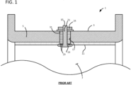
- a conventional electrode 15 includes a head 19 and a shank 21 extending away from the head.
- the shank 21 is inserted into an opening 17 forming the process penetration so the head 19 is in the conduit 7 formed by the flowtube 3 and so the shank extends through the flowtube wall 5.
- a fastener 25 e.g., a threaded nut is used to hold the electrode is in this position.
- the process penetrations should be sealed to keep the fluid from leaking into the process penetration as it flows through the flowmeter 1.
- One way this is done is to provide serrations 23 on the back side of the head 19 of each electrode 15.
- the inner surface of the flow tube 3 is commonly lined with an electrically insulating and chemically resistant liner 11 to prevent the conductive fluid from creating a short circuit between the electrode 15 and the flowtube wall 5, which is commonly made of an electrically conductive material such as metal.
- the serrations 23 on the back of the electrode head 19 dig into the liner 11 and form a seal between the head of the electrode 15 and the liner. This seal is known as the primary seal.
- the shank 21 of the electrode 15 is insulated from the electrically conductive part of the flowtube wall 5 by an insulating sheath 31 surrounding at least the segment of the shank that is adjacent the conductive flowtube wall. If fluid leaks past the primary seal, it will also have to flow past the insulating sheath 31 to completely escape through the process penetration. As a result, fluid can leak through the liner 11 and contact the flowtube 3 without any evidence of the leak being visible from outside the flowtube 3.
- the fluids metered by electromagnetic flowmeters can include very corrosive and/or caustic materials.
- the fluids can also be at a fairly high temperature when they flow through the electromagnetic meter, which can increase the rate at which the fluid causes damage to other materials (e.g., the flowtube wall 5).
- the present inventors have noted that fluids may leak past the primary seal and cause extensive corrosion of the flowtube wall 5 before a leak is detected. This can present a significant hazard because damage to the flowtube wall 5 can impair the pressure containment capability of the flowtube. Thus, the leak may not be detected until the flowtube bursts and releases the corrosive fluid in a catastrophic failure.
- WO 01/90 704 A1 discloses a magnetic flow meter with a diagnostic circuit indicating leakages from flowtube electrodes.
- the obj ect of the invention is achieved by an electromagnetic flowmeter according to claim 1 and a method of making an electromagnetic flowmeter according to claim 11, respectively.
- Preferred embodiments are disclosed in the dependent claims.
- the flowmeter has a flowtube configured to carry a flowing conductive fluid.
- the flowtube has a flowtube wall including a conductive material.
- the flowtube wall has an inner surface surrounding a fluid flow path for the conductive fluid.
- a non-conductive liner is positioned to electrically insulate the flowtube wall from the conductive fluid.
- the flowtube and non-conductive liner define an electrode mounting hole.
- An electrode extends through the electrode mounting hole.
- the electrode and the non-conductive liner form a fluidic seal between the electrode mounting hole and the fluid flow path. At least a portion of the electrode is arranged in fluid communication with the flowtube within the electrode mounting hole.
- Another aspect of the invention is a method of making an electromagnetic flowmeter.
- the method includes providing a flowtube including an axis along which fluid can flow through the flowtube.
- the flowtube also has an outer surface and an inner surface.
- the flowtube is electrically conductive and configured so that the inner surface is electrically insulated from fluid flow passing through the flowtube.
- the flowtube includes an electrode mounting hole extending radially with respect to the axis through a wall of the flowtube, including the outer surface and the inner surface.
- An electrode is installed in the electrode mounting hole so that at least a portion of the electrode in the mounting hole is in fluid communication with the flowtube wall within the electrode mounting hole.
- the electrode is operatively sealed with the outer and inner surfaces of the flowtube.
- a short circuit detector is connected to the flowtube and electrode, whereby should the seal between the electrode and the inner surface of the flowtube fail, fluid flowing through the flowtube and entering the electrode mounting hole has access to the electrode for creating a short circuit detectable by the short circuit detector.
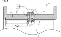
- the flowmeter 101 includes a flowtube 103 configured to carry a flowing conductive fluid through the flowmeter 101.
- the flowtube 103 suitably includes a generally cylindrical or tubular wall 105 having an inner surface surrounding a flow path 107 extending between opposite ends of the flowtube for flow of fluid through the flowmeter 101.
- the flowtube 103 is suitably made of an electrically conductive material, such as stainless steel or another suitable metal.
- a non-conductive liner 111 lines the inner surface of the flowtube wall 105 to electrically insulate the flowtube wall from the conductive fluid.
- the non-conductive liner 111 may have any of several suitable configurations, such as a coating, a separate liner attached to the inner surface of the flowtube 103, a treatment of the material of the flowtube adjacent the inner surface to provide a few examples.
- the flowmeter 101 has an electrode 115 extending through a process penetration formed by an electrode mounting hole 117 extending through the flowtube wall 105 and the non-conductive liner 111.
- the electrode 115 includes a head 119 and a shank 121 extending away from the head.
- the shank 121 has a shank diameter D1 and the head 119 has a head diameter D2 larger than the shank diameter.
- the shank 121 extends through the electrode mounting hole 117 in the flowtube wall 105 and non-conductive liner 111.
- the shank 121 is suitably threaded.
- the end of the shank 121 opposite the head 119 extends through the flowtube 103 to an exterior of the flowtube.
- a fastener 125 holds the electrode 115 so the head 119 of the electrode is in contact with the liner 111.
- the fastener is suitably a threaded nut 125 on the threaded shank 121.
- the fastener 125 is capable of applying tension to the shank 121 to draw the head 119 of the electrode 115 tightly against the liner 111.
- the threaded nut 125 can be tightened against a non-conductive washer 133 adjacent the exterior of the flowtube 103 to pull the shank 121 farther out of the electrode mounting hole 117 and draw the head 119 tightly against the liner 111 to form a seal.
- the non-conductive washer 133 suitably prevents the fastener 125 from creating an unwanted electrical connection between the flowtube 103 and the electrode shank 121.
- the head 119 suitably has a plurality of serrations or teeth 123 positioned to contact the liner 111 when the fastener 125 is tightened.
- the serrations can be omitted within the scope of the invention.
- the electrode 115 includes a threaded shank 121 and the fastener includes a threaded nut 125, it is understood that other types of fastening devices may be used without departing from the scope of the invention.
- the electrode shank 121 extends through the conductive flowtube wall 105 and is everywhere spaced apart from the flowtube wall.
- a non-conductive spacer 131 is disposed around at least a portion of the shank 121 in the electrode mounting hole 117 between the shank and the flowtube wall 105.
- the illustrated spacer 131 has at least one fluidic path 135 extending between the electrode shank 121 and the flowtube wall 105.
- the fluidic path 135 defined by the spacer 131 is substantially devoid of fluid or other conductive materials.
- the fluidic path 135 can suitably be filled with air or another non-conductive gas.
- the spacer 131 is positioned to insulate the electrode 115, and in particular the shank 121 of the electrode, from the conductive flowtube wall 105 at the process penetration under normal circumstances.
- the conductive fluid can establish a low-resistance electrical connection between the electrode 115 and the conductive flowtube wall 105.
- Leaking fluid in the fluidic path 135 establishes a short circuit between the electrode 115 and ground (i.e., the flowtube 103) that can be detected without any visual evidence of the leak.
- the spacer 131 is a cylindrically-shaped sleeve positioned so the electrode shank 121 extends through an axial hole in the sleeve for receiving the shank.
- the fluidic path 135 includes a transverse hole extending laterally through the cylindrically-shaped sleeve 131.
- the hole 135 extends laterally through the sleeve 131 from the shank 121 to the flowtube wall 105.
- the illustrated embodiment uses the spacer 131, it is also contemplated that the electrode shank 121 may be secured in spaced apart relationship with the flowtube wall 105 (and be electrically insulated therefrom) other ways without departing from the scope of the invention.
- the flowmeter includes a fluidic path between an electrode (specifically, in some embodiments, an electrode shank) and a conductive flowtube wall.
- the fluidic path is configured so that, in the event conductive fluid leaks into the fluidic path, the conductive fluid that leaks into the fluidic path establishes an electrical connection between the electrode and the conductive flowtube wall.
- the electrode is electrically insulated from the conductive flowtube wall as long as the conductive fluid does not leak into the fluidic path.
- at least a portion of the electrode (e.g., a portion of the shank) and a portion of the flowtube in the electrode mounting hole are in opposed relation, free of obstruction therebetween.
- the flowmeter 101 includes a system 141 that monitors for the presence of fluid in the fluid path 135 by assessing electrical impedance between the electrode 115 and the conductive flowtube wall 105.
- the flowmeter 101 suitably includes a short circuit detector 141 configured to detect whether or not conductive fluid is in the fluid path 135.
- a suitable short circuit detector can be formed by any electrical components that can be configured to detect electric current passing through the fluidic path 135 between the electrode shank 121 and the flowtube wall 105.
- a suitable short circuit detector can be formed by any electrical components that can be configured to detect a change in the overall electrical resistance in the electrical paths between the electrode 115 and the flowtube wall 105.
- the electrical resistance in the fluidic path 135 will be relatively high when the fluidic path is substantially devoid of fluid and much lower if the fluidic path is filled with conductive fluid.
- Those skilled in the art will be familiar with many different ways to detect the formation of a short circuit between two nodes in an electrical system (e.g., the electrode and the flowtube wall).
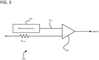
- the monitoring system 141 includes a comparator 143 that compares the resistance between two nodes (the flowtube 103 and the electrode 115) to a reference value.
- the flowtube 103 is made from conductive material, and the fluid flowing through the flowtube is likewise conductive.
- the non-conductive liner 111 extends only a certain length L1 ( Fig. 4 ) from the electrode 115.
- the fluid in the flow path 107 in normal, non-leaking conditions, electrically connects the electrode 115 to the flowtube 103 at the location where the non-conductive liner 111 ends.
- the illustrated liner 111 does not coat the entire inner surface of the flowtube 103.
- a non-conductive liner will coat the full length of the flowtube.
- the flowmeter is fluidly connected to an electrically conductive pipeline. Fluid between the electrode head and the conductive pipeline will provide a normal connection between the electrode and ground.
- the resistance between the electrode 115 and the flowtube wall 105 is approximately the same as the resistance to flow of this current through the conductive liquid. Still other connections between an electrode and ground may establish the normal electrical resistance between an electrode and a corresponding flowtube wall (ground) without departing from the scope of the invention.
- ground a corresponding flowtube wall
- the resistance between the electrode 115 and the flowtube 103 is substantially equal to the normal resistance R F , a relatively high value, which is directly related to the length L1 of fluid connecting the conductive flowtube 103 to the electrode 115 as well as the fluid's resistivity.
- R F normal resistance
- a relatively high value which is directly related to the length L1 of fluid connecting the conductive flowtube 103 to the electrode 115 as well as the fluid's resistivity.
- a new, parallel current path is created in the fluidic path 135.
- the length L2 of the fluidic path 135 is much shorter than the length L1 of fluid between the electrode head 119 and the end of the flowtube liner 111.
- the short circuit electrical resistance R L between the flowtube 103 and the electrode 115 along the fluid path 135, is much lower than the normal resistance R F .
- the total resistance R T between the flowtube 103 and the electrode 115 is much lower than when there is no leak.
- the normal (e.g., when there is no leak) resistance R F between the flowtube 103 and the electrode 115 can be calculated based on the type of fluid flowing through the flow path 107 (e.g., the resistivity of the fluid) and the length L1 between the electrode head 119 and the end of the non-conductive liner 111.
- the short circuit detector 141 is configured to detect the presence of conductive fluid in the fluidic path 135.
- An adjustable reference generator 145 supplies a reference resistance value R ref to the comparator 145.
- the reference resistance value R ref is set at a value slightly lower than the expected fluid resistance R F (e.g., between about 80% and about 95% of the expected fluid resistance R F ) and higher than the expected total resistance R T in the event of a short circuit.
- the resistance between the flowtube 105 and the electrode 115 is measured, and the measured resistance R meas is supplied to another input of the comparator 143.
- the resistance can be measured. For example, a known amount of current can be driven between the flowtube 105 and the electrode 115 for a brief time and the induced voltage during this time can be used as a measure of the resistance and/or used to calculate the resistance.
- the resistance can be measured in other ways without departing from the scope of the invention.
- the comparator 143 receives the measured resistance and compares it with the reference value R ref . If the measured resistance R meas is less than the reference value R ref , the short circuit detector 141 is configured to output an alarm. For example, it may output a signal that causes a local display to indicate the detection of a leak. Likewise, it may output a signal that is transmitted to a distributed control system.
- the flowmeter will generally have at least two electrodes on opposite sides of the flowtube. It is also understood that more than two electrodes can be included in the flowmeter, such as to provide empty pipe detection or to ground the fluid flowing through the meter.
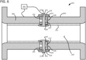
- the electromagnetic flowmeter 201 includes a conductive flowtube 203 and a non-conductive inner liner 211 that insulates the flowtube from a conductive fluid flowing in a flow path 207 extending axially through the flowtube.
- First and second electrodes 215A, 215B extend through respective process penetrations 217 in the wall 205 of the flowtube 203 at diametrically opposed positions.
- a pair of drive coils are located adjacent the outside of the flowtube 203 at diametrically opposed positions angularly spaced from the positions of the electrodes 215A, 215B about a longitudinal axis of the flowtube 203.
- the drive coils generate an electromagnetic field in the conductive fluid flowing through the flowtube 203, and the electrodes 215A, 215B detect a voltage induced in the fluid as the fluid flows through the electromagnetic field.
- the drive coils generate an electromagnetic field that has an electromagnetic field direction, and the electrodes 215A, 215B detect respective voltages induced in the fluid at diametrically opposed positions oriented perpendicular to the electromagnetic field direction.
- an insulating sheath 231 separates the shank 221 of each of the first and second electrodes 215A, 215B from the flowtube wall 205, and a non-conductive washer 233 provides electrical insulation between the flowtube wall 205 and the fastener 225 that secures each electrode to the flowtube wall.
- each electrode 215A, 215B is electrically insulated from the flowtube wall 205 at the process penetration 217.
- fluid leaks past the seal formed between the head 219 of either electrode 215A, 215B and the inner liner 211 it creates an electrical connection between the respective electrode and the flowtube wall 205 that is not present under normal operating conditions.
- the illustrated insulating sheath 231 provides a transverse hole 235 for creating a direct fluid path between the flowtube wall 205 and the respective electrode 215A, 215B, it will be understood that, even in the absence of such a sheath, leaking fluid can penetrate the seams between the insulating and conductive components to create an undesired electrical connection between the electrode and flowtube wall.
- a leak detection system 241 detects when a leak in the flowtube creates an undesired electrical connection between one of the first and second electrodes 215A, 215B and the inner liner 211.
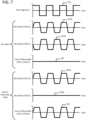
- the drive coils are configured to generate an electromagnetic field 251 that changes periodically at a drive frequency f .
- the drive frequency can be constant or variable.
- the electromagnetic field 251 is reversed at a constant drive frequency f .
- other changes in the electromagnetic field 251 can also be made periodically without departing from the scope of the invention.
- the first electrode 215A produces a first voltage signal 253A representative of an induced voltage in the fluid at the head 219 of the first electrode.
- the second electrode 215B produces a second voltage signal 253B representative of an induced voltage in the fluid at the head 219 of the second electrode.
- Respective flow-induced portions of the first and second voltage signals 253A, 253B accurately represent the induced voltages and are related to the flow rate of the fluid in the flowtube 203.
- respective noise portions of the voltage signals 253A, 253B are attributable to sources of noise (e.g., a DC potential between the first and second electrodes 215A, 215B) and detract from the accuracy of the voltage signals.
- sources of noise e.g., a DC potential between the first and second electrodes 215A, 215B
- the flow rate of the fluid flowing through the flow path 207 is related to the difference between the flow-induced portions of the first and second voltage signals 253A, 253B under normal operating conditions.
- each of the first and second voltage signal 253A, 253B changes periodically with the periodic changes in electromagnetic field strength (i.e., at the drive frequency f ).
- the flow-induced portion of the first voltage signal 253A is equal in magnitude and opposite in sign (i.e., 180° out of phase) with respect to the flow-induced portion of the second voltage signal 253B under normal operating conditions.
- the flowmeter 201 has a fluid leak, a short circuit can be created between either of the first and second electrodes 215A, 215B and the flowtube sidewall 205.
- the fluid path when a fluid path forms between one the second electrode 215B and the flowtube wall 205, the fluid path electrically connects the electrode and the flowtube wall 205, creating a short circuit at the electrode.
- the second voltage signal 253B produced by the second electrode 215B is substantially constant (i.e., does not vary significantly in response to variations in the electromagnetic field induced in the fluid by periodic changes in the drive signal 251), as illustrated in Fig. 7 .
- the leak detection system 241 is operatively connected to the first and second electrodes 215A, 215B to receive the first and second voltage signals 253A, 253B produced by the electrodes.
- the leak detection system 241 is configured to analyze a content of the at least one of the voltage signals 253A, 253B at the drive frequency f to determine whether the signal is affected by a leak.
- the leak detection system 214 can use the drive frequency content of one or both of the signals 253A, 253B to determine whether either or both of the signals vary periodically at the drive frequency f or whether the amount of variation in either of the signals at the drive frequency is suppressed below a normal (i.e., significant) amount of variation.
- the leak detection system 241 determines that one or more of the signals produced by the electrodes 241 are affected by a leak in the flowmeter, it provides an output indicative of a detected leak.
- the leak detection system 241 illustrated in Fig. 8 includes a summing amplifier 261 operatively connected to the first and second electrodes 215A, 215B to receive the first and second voltage signals 253A, 253B.
- the summing amplifier 261 is configured to add the voltage signals 253A, 253B to generate a summation signal.
- the leak detection system 241 analyzes a content of the summation signal at the drive frequency to determine whether either of the first and second voltage signals 253A, 253B is affected by a leak.
- a primary source of noise in the summation signal is caused by an inherent DC potential between the first and second electrodes 215A, 215B.
- the DC potential can be a differential mode potential, a common mode potential, or combination differential and common mode potential.
- the flow-induced portion of the first voltage signal 253A is equal in magnitude and opposite in sign (i.e., 180° out of phase) with respect to the second voltage signal 253B.
- the output of the summing amplifier 261 should be a substantially constant zero signal.
- the inherent DC potential and other noise can cause the sum of the first and second electrode signals 253A, 253B under normal operating conditions to be non-zero.
- a high pass filter 263 with a cutoff frequency set lower than the drive frequency receives the output of the summing amplifier 261.
- the high pass filter 263 suppresses at least a portion of the summation signal attributable to the DC potential between the first and second electrodes 215A, 215B.
- the high pass filter 263 outputs a filtered summation signal 265 that is substantially constant and substantially close to zero.
- a short circuit is created.
- the second voltage signal 253B becomes substantially constant.
- the second voltage signal 253B is not equal in magnitude and opposite in sign with respect to the first voltage signal 253A, and the summation signal 265 becomes periodic in nature.
- the leak detection system 241 can determine whether either of the first and second voltage signals 253A, 253B is affected by a leak in the flowmeter 201 by detecting the presence of significant periodic changes in the summation signal 265.
- the leak detection system 241 in Fig. 8 includes an analog-to-digital converter 271 that samples the summation signal 265 and generates a digital output signal (i.e., a digital summation signal) representative of the summation signal.
- a digital leak detection processor 273 receives the digital summation signal and analyzes a content of the summation signal 265 at the drive frequency f to determine whether either of the voltage signals 253A, 253B is affected by a leak in the flowmeter.
- the high pass filter 263 can eliminate some of the DC offset from the output of the summing amplifier 261 (including both common and differential DC offset), a portion of the summation signal 265 can still be attributable to the DC potential between the first and second electrodes 215A, 215B.
- the energy content of the summation signal 265 still includes frequencies above the cutoff frequency of the high pass filter 263.
- the leak detection processor 273 performs a Fourier analysis (e.g., a digital Fourier transform) on the summation signal 265 to analyze the energy content of the summation signal 265 at the drive frequency f .
- the leak detection processor 273 uses a Fourier transform to calculate a spectral number F(bin) for the summation signal 265 at the drive frequency f and converts the spectral number into an amplitude V f of the summation signal at the drive frequency (i.e., a representation of the energy of the summation signal at the drive frequency).
- the drive frequency amplitude V f should be close to zero.
- the leak detection processor determines the amplitude V f has strayed too far from zero (e.g., by comparing the amplitude to a threshold), it determines that one of the first and second voltage signals 253A, 253B is affected by a leak in the flowmeter 201 and provides an output indicative of a detected leak.
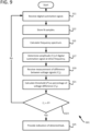
- the analog-to-digital converter 271 samples the summation signal 265 (step 311) during a sampling interval corresponding in time with one or more complete cycles of the drive signal 251 (i.e., an integral number of drive cycles).
- the leak detection processor 273 stores N samples of the summation signal 265 taken during the sampling interval in a buffer.
- the buffer stores a digital representation of the summation signal 265 over one or more complete drive cycles.
- the drive frequency f is a constant low frequency (e.g., 7 Hz) and the analog-to-digital converter 271 samples the summation signal 265 at a high frequency (e.g., 4800 Hz).
- the buffer preferably stores a large number of samples (e.g., 3500 samples), which represents several complete drive cycles (e.g., 5 drive cycles).
- the leak detection processor 273 uses Fourier analysis (e.g., the discrete Fourier transform) and the N samples stored in the buffer to calculate a spectral number F(bin) for the summation signal 265 at the drive frequency f .
- the leak detection processor 273 can use the discrete Fourier transform to calculate a frequency spectrum for the summation signal 265 and determine the spectral number F(bin) from the frequency spectrum, where bin corresponds with the spectral array index for the drive frequency f .
- the bin index for the drive frequency f can, in a suitable embodiment, be calculated by dividing the sampling frequency by the number of samples N, plus 1.
- the leak detection processor 273 can use Fourier analysis to calculate the drive frequency spectral number F(bin) directly using techniques such as cross-correlation or autocorrelation.
- the leak detection processor 273 determines the amplitude V f of the summation signal 265 at the drive frequency f using equation 1.
- V f F bin ⁇ N .
- the amplitude V f is representative of the energy in the summation signal 265 at the drive frequency f .
- the number of samples N suitably corresponds with an integral number of drive cycles. If the number of samples N does not corresponds to an integral number of drive cycles, the drive frequency will fall between two points in the frequency domain. The calculation would be less accurate due to spectral leakage. However, a gross measurement can be sufficient to detect a leak. Thus, it is understood the number of samples N does not need to be limited to the number of samples in an integral number of drive cycles to practice the invention.
- the leak detection processor 273 receives a difference signal V ⁇ representative of magnitude of a difference between the first and second voltage signals 253A, 253B from a flow rate measurement system (not shown) of the flowmeter 201.
- the leak detection processor 273 dynamically determines a threshold P as a percentage (e.g., from about 10 percent to about 40 percent) of the voltage difference V ⁇ at step 321.
- the leak detection processor 273 compares the threshold P to the amplitude V f of the summation signal 265 at the drive frequency f.
- the leak detection processor 273 If the amplitude V f is greater than the threshold P, the leak detection processor 273 provides an indication that one of the first and second voltage signals 253A, 253B is affected by a leak in the flowmeter 201 (step 325). If the amplitude V f is not greater than the threshold P, the leak detection method 301 restarts at step 311. Though the illustrated embodiment dynamically calculates the threshold P as a percentage of the voltage difference V ⁇ , it will be understood that other embodiments can compare the amplitude V f of the summation signal 265 at the drive frequency f to a constant threshold to determine whether a leak in the flowmeter 201 affects either of the voltage signals 253A, 253B.
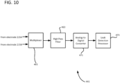
- the leak detection system 441 includes a multiplexer 461 that is operatively connected to the first and second electrodes 215A, 215B to receive the first and second voltage signals 253A, 253B from the electrodes.
- the multiplexer 461 is configured to generate a multiplexed signal, which includes alternating sequences of the voltage signals 253A, 253B spliced together serially in the time domain.
- a high pass filter 463 receives the multiplexed signal from the multiplexer 461 and suppresses a portion of the multiplexed signal attributable to a DC potential between each of the first and second electrodes 215A, 215B and ground.
- An analog-to-digital converter 471 samples the output of the high pass filter 463 and generates a digital output representative of the filtered multiplexed signal.
- a leak detection processor 473 receives the digital filtered multiplexed signal and uses it to analyze a content of the first voltage signal 253A at the drive frequency f and a content of the second voltage signal 253B at the drive frequency.
- the leak detection processor 473 compares the drive frequency contents of the first and second voltage signals 253A, 253B to determine whether either of the first and second voltage signals is affected by a leak. Though the illustrated leak detection processor 473 receives the first and second voltage signals 253A, 253B from a single input using a multiplexed signal, it is also contemplated that another leak detection processor could perform a similar processor by receiving the first and second voltage signals on two separate inputs.
- the analog-to-digital converter 471 samples the digital multiplexed signal during first and second sampling intervals (steps 511, 513).
- the samples from the first sampling interval define a first sample set representing the first voltage signal 253A and corresponding in time with one or more complete drive cycles (step 511).
- the samples from the second sampling interval suitably define a second sample set representing the second voltage signal 253B and corresponding in time with one or more complete drive cycles (step 513).
- the leak detection processor 473 stores N A samples from the first sample set in a first buffer (step 515), which collectively form a digital representation of the first voltage signal 253A during the first sampling interval.
- the leak detection processor 473 likewise stores N B samples from the second sample set in a second buffer (step 517), which collectively form a digital representation of the second voltage signal 253B during the second sampling interval.
- the leak detection processor 473 uses Fourier analysis to calculate a frequency spectrum for each of the first and second voltage signals 253A, 253B from the first and second sample sets stored in the first and second buffers (steps 519, 521). Additionally or in the alternative, the leak detection processor 473 calculates a spectral number F(bin) A , F(bin) B for each of the first and second voltage signals 253A, 253B from the stored first and second sample sets.
- the leak detection processor 473 calculates respective amplitudes V f,A , V f,B of the first and second voltage signals 253A, 253B at the drive frequency f (steps 523, 525).
- the flow-induced portions of the first and second voltage signals 253A, 253B will be substantially equal in magnitude.
- the amplitudes V f,A , V f,B of the first and second voltage signals 253A, 253B which represent the amount of energy in the respective signals at the drive frequency f , will be substantially equal under normal operating conditions.
- the amplitude V f,B of the voltage signal 253B at the drive frequency f will be significantly lower than the amplitude value V f,A of the voltage signal 253A at the drive frequency.
- the leak detection processor 473 compares the amplitude V f,A of the first voltage signal 253A to the amplitude V f,B of the second voltage signal 253B. If the leak detection processor 473 determines that the amplitude V f,A of the first voltage signal 253A is significantly different than the amplitude V f,B of the second voltage signal 253B, it provides an indication of a detected leak at step 529. If the leak detection processor 473 determines the amplitudes V f,A , V f,B of the first and second voltage signals 253A, 253B are substantially equal, it returns to steps 511 and 513 at step 531.
- the leak detection processor 473 compares the amplitude V f,A of the first voltage signal 253A to the amplitude V f,B of the second voltage signal 253B by calculating a difference between the first and second voltage signals and comparing the calculated difference to a threshold (e.g., a constant threshold or a variable threshold determined dynamically, for example, as a percentage of either of the amplitudes V f,A , V f,B ) .
- a threshold e.g., a constant threshold or a variable threshold determined dynamically, for example, as a percentage of either of the amplitudes V f,A , V f,B
- the leak detection processor 473 determines the difference between the amplitudes V f,A , V f,B of the first and second voltage signals 253A, 253B exceed the threshold, it provides an output indicative of a detected leak.
- the leak detection systems 241, 441 and the methods 301, 501 for detecting a leak in a flowmeter 201 advantageously eliminate the effects of the DC potential between the first and second electrodes 215A, 215B and other sources of noise by using Fourier analysis to isolate the content of the voltage signals 253A, 253B at the drive frequency f from portions of the signal.
- the amplitude(s) of the voltage signals 253A, 253B at the drive frequency f represent the flow-induced portion of the voltage signals and suppress other portions of the voltage signals.
- only those portions of the voltage signals 253A, 253B that accurately reflect whether the voltage signals properly vary with periodic changes in the electromagnetic field are used to determine whether a leak affects either of the voltage signals.
- the construction of the insulating sleeves 117, 217 creates a direct fluid path between the electrodes 115, 215A, 215B and the respective flowtube walls 105, 205, which creates an intentional short circuit when a leak is present that is readily detectable using the leak detection systems 141, 241, 441.
Landscapes
- Physics & Mathematics (AREA)
- General Physics & Mathematics (AREA)
- Fluid Mechanics (AREA)
- Electromagnetism (AREA)
- Measuring Volume Flow (AREA)
Claims (13)
- Elektromagnetischer Durchflussmesser (101) miteinem Strömungsrohr (103), das zum Führen eines strömenden leitenden Strömungsmittels gestaltet ist, wobei das Strömungsrohr (103) eine Strömungsrohrwand (105) hat, die ein leitendes Material aufweist, wobei die Strömungsrohrwand (103) eine einen Strömungsmittel-Strömungsweg (107) für das leitende Strömungsmittel umgebende innere Oberfläche hat;einer nichtleitenden Auskleidung (111), die positioniert ist, um die Strömungsrohrwand (105) gegen das leitende Strömungsmittel elektrisch abzuschirmen, wobei das Strömungsrohr (103) und die nichtleitende Auskleidung (111) ein Elektrodenmontageloch (117) begrenzen;einer Elektrode (115), die sich durch das Elektrodenmontageloch (117) erstreckt, wobei die Elektrode (115) und die nichtleitende Auskleidung (111) eine Strömungsmitteldichtung zwischen dem Elektrodenmontageloch (117) und dem Strömungsmittel-Strömungsweg (107) bilden,einem nichtleitenden Distanzstück (131), das um mindestens einen Teil der Elektrode (115) herum in dem Elektrodenmontageloch (117) zwischen der Elektrode (115) und der Strömungsrohrwand (105) angeordnet ist, wobei das nichtleitende Distanzstück (131) eine zylindrisch geformte Hülse aufweist,wobei mindestens ein Teil der Elektrode (115) in Strömungsmittelverbindung mit dem Strömungsrohr (103) innerhalb des Elektrodenmontageloches (117) angeordnet ist,dadurch gekennzeichnet, dass
das nichtleitende Distanzstück (131) mindestens einen Strömungsmittelweg hat, der sich zwischen der Elektrode (115) und der Strömungsrohrwand (105) erstreckt, so dass das leitende Strömungsmittel eine elektrische Verbindung zwischen der Elektrode (115) und der Strömungsrohrwand (105) im Fall, dass das leitende Strömungsmittel in den Strömungsmittelweg (135) eindringt, herstellen kann,wobei der Strömungsmittelweg (135) ein quer verlaufendes Loch in der zylindrisch geformten Hülse ist. - Elektromagnetischer Durchflussmesser (101) nach Anspruch 1, bei dem der Teil der Elektrode (115) und ein Teil des Strömungsrohres (103) in dem Elektrodenmontageloch (117) in entgegengesetzter Beziehung frei von Hindernissen dazwischen sind.
- Elektromagnetischer Durchflussmesser (101) nach einem der vorhergehenden Ansprüche, bei dem die Elektrode (115) einen Kopf (119) und einen Schaft (121) aufweist, wobei die zylindrisch geformte Hülse ein axiales Loch hat, das zum Aufnehmen des Schaftes (121) gestaltet ist.
- Elektromagnetischer Durchflussmesser (101) nach Anspruch 3, bei dem sich das quer verlaufende Loch vorzugsweise von dem Schaft (121) bis zu der Strömungsrohrwand (105) erstreckt.
- Elektromagnetischer Durchflussmesser (101) nach einem der vorhergehenden Ansprüche, des Weiteren mit einem Kurzschlussdetektor (141), der konfiguriert ist, um zu erkennen, ob leitendes Strömungsmittel in dem Strömungsmittelweg (135) ist.
- Elektromagnetischer Durchflussmesser (101) nach Anspruch 5, bei dem der Kurzschlussdetektor konfiguriert ist, um einen durch das leitende Strömungsmittel fließenden Strom zu erkennen.
- Elektromagnetischer Durchflussmesser (101) nach Anspruch 5 oder 6, bei dem der Kurzschlussdetektor konfiguriert ist, um eine Veränderung in einem Widerstand in einem elektrischen Pfad zwischen der Elektrode und der Strömungsrohrwand zu erkennen.
- Elektromagnetischer Durchflussmesser (101) nach einem der Ansprüche 5 bis 7, bei dem der Kurzschlussdetektor (141) konfiguriert ist, um einen Alarm auszugeben, wenn er das leitende Strömungsmittel in dem Strömungsmittelweg (135) wahrnimmt.
- Elektromagnetischer Durchflussmesser (101) nach einem der vorhergehenden Ansprüche, bei dem die Elektrode (115) einen Kopf (119) und einen Schaft (121) aufweist, wobei der Kopf (119) einen Kopfdurchmesser hat und der Schaft (121) einen Schaftdurchmesser hat und der Kopfdurchmesser größer als der Schaftdurchmesser ist.
- Elektromagnetischer Durchflussmesser (101) nach Anspruch 9, bei dem der Kopf (119) Zähne (123) aufweist, die gestaltet sind, um die nichtleitende Auskleidung (111) zu berühren, um dabei zu helfen, die Strömungsmitteldichtung zu bilden.
- Verfahren zum Herstellen eines elektromagnetischen Durchflussmessers (101), das Folgendes umfasst:Bereitstellen eines Strömungsrohres (103) mit einer Achse, an der entlang ein Strömungsmittel durch das Strömungsrohr (103) strömen kann, einer äußeren Oberfläche und einer inneren Oberfläche, wobei das Strömungsrohr (103) elektrisch leitend ist und so gestaltet ist, dass die innere Oberfläche gegen den durch das Strömungsrohr (103) gehenden Strömungsmittelstrom elektrisch abgeschirmt ist, wobei das Strömungsrohr (103) weiterhin ein Elektrodenmontageloch (117) enthält, das sich radial bezüglich der Achse durch eine Wand (105) des Strömungsrohres (103), die äußere Oberfläche und die innere Oberfläche erstreckt;Einbauen einer Elektrode (115) in das Elektrodenmontageloch (117), so dass mindestens ein Teil der Elektrode (115) in dem Montageloch (117) in Strömungsmittelverbindung mit der Strömungsrohrwand (105) innerhalb des Elektrodenmontageloches (117) ist;wirksames Abdichten der Elektrode (115) mit der äußeren und inneren Oberfläche des Strömungsrohres (103);Verbinden eines Kurzschlussdetektors (141) mit dem Strömungsrohr (103) und der Elektrode (115), wodurch im Fall, dass die Dichtung zwischen der Elektrode (115) und der inneren Oberfläche des Strömungsrohres (103) versagt, das durch das Strömungsrohr (103) strömende und in das Elektrodenmontageloch (117) eintretende Strömungsmittel Zutritt zu der Elektrode (115) hat, um einen von dem Kurzschlussdetektor (141) erkennbaren Kurzschluss herzustellen,Platzieren eines nichtleitenden Distanzstückes (131) auf der Elektrode (115), wobei das nichtleitende Distanzstück (131) eine zylindrisch geformte Hülse aufweist, dadurch gekennzeichnet, dass das nichtleitende Distanzstück (131) mindestens einen Strömungsmittelweg (135) hat, der sich zwischen der Elektrode (115) und der Strömungsrohrwand (105) innerhalb des Elektrodenmontageloches (117) erstreckt, wobei der Strömungsmittelweg (135) ein quer verlaufendes Loch in der zylindrisch geformten Hülse ist.
- Verfahren nach Anspruch 11, bei dem das Bereitstellen der Elektrode (115) das Anordnen eines Teiles der Elektrode (115) innerhalb des Elektrodenmontageloches (117) aufweist, so dass der Elektrodenteil und ein Teil der Strömungsrohrwand (105) in dem Elektrodenmontageloch (117) in entgegengesetzter Beziehung frei von Hindernissen dazwischen angeordnet sind.
- Verfahren nach einem der Ansprüche 11 bis 12, bei dem das Bereitstellen des Strömungsrohres (103) das Anordnen einer nichtleitenden Auskleidung (111) bezüglich der inneren Oberfläche des Strömungsrohres (103) einschließt, um eine elektrische Leitung zwischen dem Strömungsmittel, wenn es durch das Strömungsrohr (103) strömt, und der inneren Oberfläche des Strömungsrohres (103) zu unterbinden.
Applications Claiming Priority (1)
| Application Number | Priority Date | Filing Date | Title |
|---|---|---|---|
| US14/659,210 US9810559B2 (en) | 2015-03-16 | 2015-03-16 | Systems and methods for detecting leaks in an electromagnetic flowmeter |
Publications (4)
| Publication Number | Publication Date |
|---|---|
| EP3070441A2 EP3070441A2 (de) | 2016-09-21 |
| EP3070441A3 EP3070441A3 (de) | 2017-03-08 |
| EP3070441B1 true EP3070441B1 (de) | 2024-09-25 |
| EP3070441C0 EP3070441C0 (de) | 2024-09-25 |
Family
ID=55542525
Family Applications (1)
| Application Number | Title | Priority Date | Filing Date |
|---|---|---|---|
| EP16160725.4A Active EP3070441B1 (de) | 2015-03-16 | 2016-03-16 | System und verfahren zum erkennen von lecks in einem magnetisch-induktiven durchflussmesser |
Country Status (3)
| Country | Link |
|---|---|
| US (2) | US9810559B2 (de) |
| EP (1) | EP3070441B1 (de) |
| CN (1) | CN106092226B (de) |
Families Citing this family (11)
| Publication number | Priority date | Publication date | Assignee | Title |
|---|---|---|---|---|
| CN110945324B (zh) * | 2017-05-11 | 2021-07-02 | Abb瑞士股份有限公司 | 用于配置电磁流量计的方法和系统 |
| US10416011B2 (en) * | 2017-10-16 | 2019-09-17 | Finetek Co., Ltd. | Electromagnetic flowmeter with adjustable electrode structures |
| US11281878B2 (en) * | 2018-02-20 | 2022-03-22 | Fresenius Medical Care Holdings, Inc. | Wetness detection with biometric sensor device for use in blood treatment |
| US10712184B1 (en) * | 2019-01-09 | 2020-07-14 | Georg Fischer Signet Llc | Magnetic flowmeter assembly having independent coil drive and control system |
| CN109577957B (zh) * | 2019-01-21 | 2022-04-29 | 西南石油大学 | 一种基于相关传感阵列的环空流量电磁测量装置及测量方法 |
| DE102020123941A1 (de) | 2020-09-15 | 2022-03-17 | Krohne Messtechnik Gmbh | Verfahren zum Betreiben eines magnetisch-induktiven Durchflussmessgeräts und entsprechendes magnetisch-induktives Durchflussmessgerät |
| DE102020129772A1 (de) * | 2020-11-11 | 2022-05-12 | Endress+Hauser Flowtec Ag | Magnetisch-induktives Durchflussmessgerät |
| CN112525953A (zh) * | 2020-11-18 | 2021-03-19 | 上海览宋科技有限公司 | 液体传感器、液体传感器的破损检测装置及破损检测方法 |
| CN115507905B (zh) * | 2022-05-23 | 2025-11-28 | 浙江迪元仪表有限公司 | 一种测量传感器对地绝缘电阻的电磁水表 |
| DE102023102673B3 (de) * | 2023-02-03 | 2024-05-16 | Krohne Messtechnik Gmbh | Verfahren zum Betreiben eines magnetisch-induktiven Durchflussmessgeräts und ein entsprechendes magnetisch-induktives Durchflussmessgerät |
| CN120628830B (zh) * | 2025-08-14 | 2025-10-21 | 四川铭帝铝业有限公司 | 一种侧压门窗载荷力检测装置 |
Citations (1)
| Publication number | Priority date | Publication date | Assignee | Title |
|---|---|---|---|---|
| US4773275A (en) * | 1986-05-27 | 1988-09-27 | The Foxboro Company | Seal for ceramic flow tube |
Family Cites Families (19)
| Publication number | Priority date | Publication date | Assignee | Title |
|---|---|---|---|---|
| US4741215A (en) * | 1985-07-03 | 1988-05-03 | Rosemount Inc. | Flow tube for a magnetic flowmeter |
| US6611775B1 (en) | 1998-12-10 | 2003-08-26 | Rosemount Inc. | Electrode leakage diagnostics in a magnetic flow meter |
| JP4045528B2 (ja) | 2000-11-06 | 2008-02-13 | 横河電機株式会社 | 電磁流量計 |
| JP2003028683A (ja) | 2001-07-13 | 2003-01-29 | Yokogawa Electric Corp | 電磁流量計 |
| US7279903B2 (en) * | 2005-05-02 | 2007-10-09 | Invensys Systems, Inc. | Non-metallic flow-through electrodeless conductivity sensor with leak and temperature detection |
| CN201007665Y (zh) | 2006-10-20 | 2008-01-16 | 上海威尔泰工业自动化股份有限公司 | 可在线检测电极泄漏的电磁流量计 |
| DE102006054635A1 (de) * | 2006-11-17 | 2008-05-21 | Endress + Hauser Flowtec Ag | Vorrichtung zum Messen des Volumen- oder Massestroms eines Mediums in einer Rohrleitung |
| DE102007058898A1 (de) * | 2007-12-05 | 2009-06-10 | Endress + Hauser Flowtec Ag | Elektrode für ein magnetisch-induktives Durchflussmessgerät |
| EP2313749B1 (de) * | 2008-07-29 | 2021-04-21 | Micro Motion, Inc. | Hochdruckflussmesser mit belastungsresistenter elektrodenanordnung |
| JP4886754B2 (ja) | 2008-10-02 | 2012-02-29 | 株式会社オーバル | 電磁流量計及び絶縁抵抗計測方法 |
| JP5202368B2 (ja) * | 2009-02-03 | 2013-06-05 | 株式会社東芝 | 測定装置 |
| US7921734B2 (en) | 2009-05-12 | 2011-04-12 | Rosemount Inc. | System to detect poor process ground connections |
| JP5462062B2 (ja) * | 2010-04-22 | 2014-04-02 | アズビル株式会社 | 電磁流量計 |
| US8682600B2 (en) * | 2011-07-06 | 2014-03-25 | Saudi Arabian Oil Company | Pipeline leak detection and location system through pressure and cathodic protection soil |
| US10641627B2 (en) * | 2013-12-20 | 2020-05-05 | Rosemount Inc. | Magnetic flowmeter with automatic operating setpoint selection |
| US9464927B2 (en) * | 2014-09-30 | 2016-10-11 | Micro Motion, Inc. | Magnetic flowmeter flowtube with process fluid venting assembly |
| US9658089B2 (en) * | 2014-10-01 | 2017-05-23 | Finetek Co., Ltd. | Electromagnetic flowmeter with voltage-amplitude conductivity-sensing function for a liquid in a tube |
| US9285256B1 (en) * | 2014-10-27 | 2016-03-15 | Finetek Co., Ltd. | Electromagnetic flowmeter with variable-frequency conductivity-sensing function for a liquid in a tube |
| CN104317315B (zh) * | 2014-11-20 | 2017-06-13 | 陈一其 | 一种液位控制开关装置和控制电路 |
-
2015
- 2015-03-16 US US14/659,210 patent/US9810559B2/en active Active
-
2016
- 2016-03-16 CN CN201610383155.7A patent/CN106092226B/zh active Active
- 2016-03-16 EP EP16160725.4A patent/EP3070441B1/de active Active
-
2017
- 2017-10-10 US US15/728,722 patent/US10175074B2/en active Active
Patent Citations (1)
| Publication number | Priority date | Publication date | Assignee | Title |
|---|---|---|---|---|
| US4773275A (en) * | 1986-05-27 | 1988-09-27 | The Foxboro Company | Seal for ceramic flow tube |
Also Published As
| Publication number | Publication date |
|---|---|
| EP3070441A3 (de) | 2017-03-08 |
| US20160273948A1 (en) | 2016-09-22 |
| CN106092226B (zh) | 2020-08-07 |
| EP3070441A2 (de) | 2016-09-21 |
| US20180031400A1 (en) | 2018-02-01 |
| US9810559B2 (en) | 2017-11-07 |
| CN106092226A (zh) | 2016-11-09 |
| US10175074B2 (en) | 2019-01-08 |
| EP3070441C0 (de) | 2024-09-25 |
Similar Documents
| Publication | Publication Date | Title |
|---|---|---|
| EP3070441B1 (de) | System und verfahren zum erkennen von lecks in einem magnetisch-induktiven durchflussmesser | |
| AU2015413844B2 (en) | Real time integrity monitoring of on-shore pipes | |
| EP2283329B1 (de) | Verfahren zur erzeugung einer diagnostik aus einer abweichung eines strömungsmesserparameters | |
| EP2800963B1 (de) | Überwachung einer leitfähigen fluidleitung | |
| EP2423647A1 (de) | Vorrichtung zur Verwendung bei der Bestimmung mehrerer Eigenschaften einer Mehrphasenströmung in einem Rohr | |
| US20080282781A1 (en) | Monitoring Particles in a Fluid Stream | |
| WO2011128656A1 (en) | Means and method for monitoring the flow of fluid | |
| JP6408553B2 (ja) | 接着ptfe電極を備えた磁気流量計 | |
| US20080127712A1 (en) | In-Situ Calibration Verification Device and Method for Electromagnetic Flowmeters | |
| US8601883B2 (en) | Acoustic sensor for averaging pitot tube installation | |
| EP2893300A1 (de) | Differentialdruckströmungsmesser mit abgewinkelten druckanschlüssen | |
| US9228867B2 (en) | Apparatus for characterising a flow through a conduit | |
| NO327658B1 (no) | Anordning og fremgangsmate for maling av vanninnhold og saltkonsentrasjon i en flerfasefluidstrom | |
| EP3460451A2 (de) | Integritätsüberwachungszwischenrohr | |
| KR101573679B1 (ko) | 접지링 구조를 갖는 전자유량계 | |
| EP3931533B1 (de) | Vorrichtung zur messung der durchflussmenge eines gases in einer gasleitung | |
| JP5877260B1 (ja) | 電磁流量計の空状態判定方法 | |
| US10914709B2 (en) | Internal/external discrimination of metal loss defects | |
| EP1943494B1 (de) | Beobachten von partikeln in einem flüssigkeitsstrom | |
| JP2005265663A (ja) | 埋設配管および漏洩位置の特定方法 | |
| US7095222B2 (en) | Leak detection method and system in nonmetallic underground pipes | |
| KR101573678B1 (ko) | 디지털 필터를 이용한 균등자계분포 방식의 전자유량계 | |
| JP2532038B2 (ja) | 管路内面被覆の探傷方法 | |
| RU2310816C2 (ru) | Вихревой электромагнитный преобразователь расхода жидкого металла | |
| CN215178056U (zh) | 一种高精度电磁流量计标定系统 |
Legal Events
| Date | Code | Title | Description |
|---|---|---|---|
| PUAI | Public reference made under article 153(3) epc to a published international application that has entered the european phase |
Free format text: ORIGINAL CODE: 0009012 |
|
| AK | Designated contracting states |
Kind code of ref document: A2 Designated state(s): AL AT BE BG CH CY CZ DE DK EE ES FI FR GB GR HR HU IE IS IT LI LT LU LV MC MK MT NL NO PL PT RO RS SE SI SK SM TR |
|
| AX | Request for extension of the european patent |
Extension state: BA ME |
|
| PUAL | Search report despatched |
Free format text: ORIGINAL CODE: 0009013 |
|
| AK | Designated contracting states |
Kind code of ref document: A3 Designated state(s): AL AT BE BG CH CY CZ DE DK EE ES FI FR GB GR HR HU IE IS IT LI LT LU LV MC MK MT NL NO PL PT RO RS SE SI SK SM TR |
|
| AX | Request for extension of the european patent |
Extension state: BA ME |
|
| RIC1 | Information provided on ipc code assigned before grant |
Ipc: G01F 1/60 20060101ALI20170201BHEP Ipc: G01F 1/58 20060101AFI20170201BHEP |
|
| STAA | Information on the status of an ep patent application or granted ep patent |
Free format text: STATUS: REQUEST FOR EXAMINATION WAS MADE |
|
| 17P | Request for examination filed |
Effective date: 20170908 |
|
| RBV | Designated contracting states (corrected) |
Designated state(s): AL AT BE BG CH CY CZ DE DK EE ES FI FR GB GR HR HU IE IS IT LI LT LU LV MC MK MT NL NO PL PT RO RS SE SI SK SM TR |
|
| RAP1 | Party data changed (applicant data changed or rights of an application transferred) |
Owner name: SCHNEIDER ELECTRIC SYSTEMS USA, INC. |
|
| RAP3 | Party data changed (applicant data changed or rights of an application transferred) |
Owner name: SCHNEIDER ELECTRIC SYSTEMS USA, INC. |
|
| STAA | Information on the status of an ep patent application or granted ep patent |
Free format text: STATUS: EXAMINATION IS IN PROGRESS |
|
| 17Q | First examination report despatched |
Effective date: 20210531 |
|
| GRAP | Despatch of communication of intention to grant a patent |
Free format text: ORIGINAL CODE: EPIDOSNIGR1 |
|
| STAA | Information on the status of an ep patent application or granted ep patent |
Free format text: STATUS: GRANT OF PATENT IS INTENDED |
|
| INTG | Intention to grant announced |
Effective date: 20240430 |
|
| GRAS | Grant fee paid |
Free format text: ORIGINAL CODE: EPIDOSNIGR3 |
|
| GRAA | (expected) grant |
Free format text: ORIGINAL CODE: 0009210 |
|
| STAA | Information on the status of an ep patent application or granted ep patent |
Free format text: STATUS: THE PATENT HAS BEEN GRANTED |
|
| AK | Designated contracting states |
Kind code of ref document: B1 Designated state(s): AL AT BE BG CH CY CZ DE DK EE ES FI FR GB GR HR HU IE IS IT LI LT LU LV MC MK MT NL NO PL PT RO RS SE SI SK SM TR |
|
| REG | Reference to a national code |
Ref country code: GB Ref legal event code: FG4D |
|
| REG | Reference to a national code |
Ref country code: CH Ref legal event code: EP |
|
| REG | Reference to a national code |
Ref country code: DE Ref legal event code: R096 Ref document number: 602016089515 Country of ref document: DE |
|
| REG | Reference to a national code |
Ref country code: IE Ref legal event code: FG4D |
|
| U01 | Request for unitary effect filed |
Effective date: 20240925 |
|
| U07 | Unitary effect registered |
Designated state(s): AT BE BG DE DK EE FI FR IT LT LU LV MT NL PT RO SE SI Effective date: 20241014 |
|
| PG25 | Lapsed in a contracting state [announced via postgrant information from national office to epo] |
Ref country code: NO Free format text: LAPSE BECAUSE OF FAILURE TO SUBMIT A TRANSLATION OF THE DESCRIPTION OR TO PAY THE FEE WITHIN THE PRESCRIBED TIME-LIMIT Effective date: 20241225 |
|
| PG25 | Lapsed in a contracting state [announced via postgrant information from national office to epo] |
Ref country code: GR Free format text: LAPSE BECAUSE OF FAILURE TO SUBMIT A TRANSLATION OF THE DESCRIPTION OR TO PAY THE FEE WITHIN THE PRESCRIBED TIME-LIMIT Effective date: 20241226 |
|
| PG25 | Lapsed in a contracting state [announced via postgrant information from national office to epo] |
Ref country code: RS Free format text: LAPSE BECAUSE OF FAILURE TO SUBMIT A TRANSLATION OF THE DESCRIPTION OR TO PAY THE FEE WITHIN THE PRESCRIBED TIME-LIMIT Effective date: 20241225 |
|
| PG25 | Lapsed in a contracting state [announced via postgrant information from national office to epo] |
Ref country code: RS Free format text: LAPSE BECAUSE OF FAILURE TO SUBMIT A TRANSLATION OF THE DESCRIPTION OR TO PAY THE FEE WITHIN THE PRESCRIBED TIME-LIMIT Effective date: 20241225 Ref country code: NO Free format text: LAPSE BECAUSE OF FAILURE TO SUBMIT A TRANSLATION OF THE DESCRIPTION OR TO PAY THE FEE WITHIN THE PRESCRIBED TIME-LIMIT Effective date: 20241225 Ref country code: GR Free format text: LAPSE BECAUSE OF FAILURE TO SUBMIT A TRANSLATION OF THE DESCRIPTION OR TO PAY THE FEE WITHIN THE PRESCRIBED TIME-LIMIT Effective date: 20241226 |
|
| PG25 | Lapsed in a contracting state [announced via postgrant information from national office to epo] |
Ref country code: IS Free format text: LAPSE BECAUSE OF FAILURE TO SUBMIT A TRANSLATION OF THE DESCRIPTION OR TO PAY THE FEE WITHIN THE PRESCRIBED TIME-LIMIT Effective date: 20250125 |
|
| PG25 | Lapsed in a contracting state [announced via postgrant information from national office to epo] |
Ref country code: SM Free format text: LAPSE BECAUSE OF FAILURE TO SUBMIT A TRANSLATION OF THE DESCRIPTION OR TO PAY THE FEE WITHIN THE PRESCRIBED TIME-LIMIT Effective date: 20240925 |
|
| PG25 | Lapsed in a contracting state [announced via postgrant information from national office to epo] |
Ref country code: ES Free format text: LAPSE BECAUSE OF FAILURE TO SUBMIT A TRANSLATION OF THE DESCRIPTION OR TO PAY THE FEE WITHIN THE PRESCRIBED TIME-LIMIT Effective date: 20240925 |
|
| PG25 | Lapsed in a contracting state [announced via postgrant information from national office to epo] |
Ref country code: CZ Free format text: LAPSE BECAUSE OF FAILURE TO SUBMIT A TRANSLATION OF THE DESCRIPTION OR TO PAY THE FEE WITHIN THE PRESCRIBED TIME-LIMIT Effective date: 20240925 Ref country code: PL Free format text: LAPSE BECAUSE OF FAILURE TO SUBMIT A TRANSLATION OF THE DESCRIPTION OR TO PAY THE FEE WITHIN THE PRESCRIBED TIME-LIMIT Effective date: 20240925 |
|
| PG25 | Lapsed in a contracting state [announced via postgrant information from national office to epo] |
Ref country code: SK Free format text: LAPSE BECAUSE OF FAILURE TO SUBMIT A TRANSLATION OF THE DESCRIPTION OR TO PAY THE FEE WITHIN THE PRESCRIBED TIME-LIMIT Effective date: 20240925 |
|
| PGFP | Annual fee paid to national office [announced via postgrant information from national office to epo] |
Ref country code: GB Payment date: 20250325 Year of fee payment: 10 |
|
| U20 | Renewal fee for the european patent with unitary effect paid |
Year of fee payment: 10 Effective date: 20250325 |
|
| PLBE | No opposition filed within time limit |
Free format text: ORIGINAL CODE: 0009261 |
|
| STAA | Information on the status of an ep patent application or granted ep patent |
Free format text: STATUS: NO OPPOSITION FILED WITHIN TIME LIMIT |
|
| 26N | No opposition filed |
Effective date: 20250626 |
|
| PG25 | Lapsed in a contracting state [announced via postgrant information from national office to epo] |
Ref country code: MC Free format text: LAPSE BECAUSE OF FAILURE TO SUBMIT A TRANSLATION OF THE DESCRIPTION OR TO PAY THE FEE WITHIN THE PRESCRIBED TIME-LIMIT Effective date: 20240925 |
|
| REG | Reference to a national code |
Ref country code: CH Ref legal event code: H13 Free format text: ST27 STATUS EVENT CODE: U-0-0-H10-H13 (AS PROVIDED BY THE NATIONAL OFFICE) Effective date: 20251023 |