EP3070243B1 - Door fitting for height adjustment of sliding doors - Google Patents
Door fitting for height adjustment of sliding doors Download PDFInfo
- Publication number
- EP3070243B1 EP3070243B1 EP16000623.5A EP16000623A EP3070243B1 EP 3070243 B1 EP3070243 B1 EP 3070243B1 EP 16000623 A EP16000623 A EP 16000623A EP 3070243 B1 EP3070243 B1 EP 3070243B1
- Authority
- EP
- European Patent Office
- Prior art keywords
- door
- housing
- sliding door
- accessory mechanism
- lift plunger
- Prior art date
- Legal status (The legal status is an assumption and is not a legal conclusion. Google has not performed a legal analysis and makes no representation as to the accuracy of the status listed.)
- Not-in-force
Links
- 238000003780 insertion Methods 0.000 claims description 8
- 230000037431 insertion Effects 0.000 claims description 8
- 230000000979 retarding effect Effects 0.000 claims 1
- 230000001133 acceleration Effects 0.000 description 14
- 125000006850 spacer group Chemical group 0.000 description 5
- 241000282472 Canis lupus familiaris Species 0.000 description 2
- 238000006073 displacement reaction Methods 0.000 description 2
- 239000011521 glass Substances 0.000 description 2
- 238000007789 sealing Methods 0.000 description 2
- 229910052782 aluminium Inorganic materials 0.000 description 1
- XAGFODPZIPBFFR-UHFFFAOYSA-N aluminium Chemical compound [Al] XAGFODPZIPBFFR-UHFFFAOYSA-N 0.000 description 1
- 230000001419 dependent effect Effects 0.000 description 1
- 238000004146 energy storage Methods 0.000 description 1
- 230000005484 gravity Effects 0.000 description 1
- 229910052751 metal Inorganic materials 0.000 description 1
- 239000002184 metal Substances 0.000 description 1
- 239000004033 plastic Substances 0.000 description 1
- 239000007787 solid Substances 0.000 description 1
- 239000002023 wood Substances 0.000 description 1
Images


Classifications
-
- E—FIXED CONSTRUCTIONS
- E05—LOCKS; KEYS; WINDOW OR DOOR FITTINGS; SAFES
- E05D—HINGES OR SUSPENSION DEVICES FOR DOORS, WINDOWS OR WINGS
- E05D15/00—Suspension arrangements for wings
- E05D15/06—Suspension arrangements for wings for wings sliding horizontally more or less in their own plane
- E05D15/0621—Details, e.g. suspension or supporting guides
- E05D15/066—Details, e.g. suspension or supporting guides for wings supported at the bottom
- E05D15/0665—Details, e.g. suspension or supporting guides for wings supported at the bottom on wheels with fixed axis
- E05D15/0669—Details, e.g. suspension or supporting guides for wings supported at the bottom on wheels with fixed axis with height adjustment
-
- E—FIXED CONSTRUCTIONS
- E05—LOCKS; KEYS; WINDOW OR DOOR FITTINGS; SAFES
- E05F—DEVICES FOR MOVING WINGS INTO OPEN OR CLOSED POSITION; CHECKS FOR WINGS; WING FITTINGS NOT OTHERWISE PROVIDED FOR, CONCERNED WITH THE FUNCTIONING OF THE WING
- E05F1/00—Closers or openers for wings, not otherwise provided for in this subclass
- E05F1/08—Closers or openers for wings, not otherwise provided for in this subclass spring-actuated, e.g. for horizontally sliding wings
- E05F1/16—Closers or openers for wings, not otherwise provided for in this subclass spring-actuated, e.g. for horizontally sliding wings for sliding wings
-
- E—FIXED CONSTRUCTIONS
- E05—LOCKS; KEYS; WINDOW OR DOOR FITTINGS; SAFES
- E05F—DEVICES FOR MOVING WINGS INTO OPEN OR CLOSED POSITION; CHECKS FOR WINGS; WING FITTINGS NOT OTHERWISE PROVIDED FOR, CONCERNED WITH THE FUNCTIONING OF THE WING
- E05F5/00—Braking devices, e.g. checks; Stops; Buffers
- E05F5/003—Braking devices, e.g. checks; Stops; Buffers for sliding wings
-
- E—FIXED CONSTRUCTIONS
- E06—DOORS, WINDOWS, SHUTTERS, OR ROLLER BLINDS IN GENERAL; LADDERS
- E06B—FIXED OR MOVABLE CLOSURES FOR OPENINGS IN BUILDINGS, VEHICLES, FENCES OR LIKE ENCLOSURES IN GENERAL, e.g. DOORS, WINDOWS, BLINDS, GATES
- E06B3/00—Window sashes, door leaves, or like elements for closing wall or like openings; Layout of fixed or moving closures, e.g. windows in wall or like openings; Features of rigidly-mounted outer frames relating to the mounting of wing frames
- E06B3/32—Arrangements of wings characterised by the manner of movement; Arrangements of movable wings in openings; Features of wings or frames relating solely to the manner of movement of the wing
- E06B3/34—Arrangements of wings characterised by the manner of movement; Arrangements of movable wings in openings; Features of wings or frames relating solely to the manner of movement of the wing with only one kind of movement
- E06B3/42—Sliding wings; Details of frames with respect to guiding
- E06B3/46—Horizontally-sliding wings
- E06B3/4636—Horizontally-sliding wings for doors
-
- E—FIXED CONSTRUCTIONS
- E05—LOCKS; KEYS; WINDOW OR DOOR FITTINGS; SAFES
- E05D—HINGES OR SUSPENSION DEVICES FOR DOORS, WINDOWS OR WINGS
- E05D15/00—Suspension arrangements for wings
- E05D15/56—Suspension arrangements for wings with successive different movements
- E05D15/565—Suspension arrangements for wings with successive different movements for raising wings before sliding
-
- E—FIXED CONSTRUCTIONS
- E05—LOCKS; KEYS; WINDOW OR DOOR FITTINGS; SAFES
- E05Y—INDEXING SCHEME RELATING TO HINGES OR OTHER SUSPENSION DEVICES FOR DOORS, WINDOWS OR WINGS AND DEVICES FOR MOVING WINGS INTO OPEN OR CLOSED POSITION, CHECKS FOR WINGS AND WING FITTINGS NOT OTHERWISE PROVIDED FOR, CONCERNED WITH THE FUNCTIONING OF THE WING
- E05Y2201/00—Constructional elements; Accessories therefore
- E05Y2201/60—Suspension or transmission members; Accessories therefore
- E05Y2201/622—Suspension or transmission members elements
- E05Y2201/638—Cams; Ramps
-
- E—FIXED CONSTRUCTIONS
- E05—LOCKS; KEYS; WINDOW OR DOOR FITTINGS; SAFES
- E05Y—INDEXING SCHEME RELATING TO HINGES OR OTHER SUSPENSION DEVICES FOR DOORS, WINDOWS OR WINGS AND DEVICES FOR MOVING WINGS INTO OPEN OR CLOSED POSITION, CHECKS FOR WINGS AND WING FITTINGS NOT OTHERWISE PROVIDED FOR, CONCERNED WITH THE FUNCTIONING OF THE WING
- E05Y2600/00—Mounting or coupling arrangements for elements provided for in this subclass
- E05Y2600/40—Mounting location; Visibility of the elements
- E05Y2600/456—Mounting location; Visibility of the elements in or on a suspension member
-
- E—FIXED CONSTRUCTIONS
- E05—LOCKS; KEYS; WINDOW OR DOOR FITTINGS; SAFES
- E05Y—INDEXING SCHEME RELATING TO HINGES OR OTHER SUSPENSION DEVICES FOR DOORS, WINDOWS OR WINGS AND DEVICES FOR MOVING WINGS INTO OPEN OR CLOSED POSITION, CHECKS FOR WINGS AND WING FITTINGS NOT OTHERWISE PROVIDED FOR, CONCERNED WITH THE FUNCTIONING OF THE WING
- E05Y2800/00—Details, accessories and auxiliary operations not otherwise provided for
- E05Y2800/20—Combinations of elements
- E05Y2800/23—Combinations of elements of elements of different categories
- E05Y2800/24—Combinations of elements of elements of different categories of springs and brakes
-
- E—FIXED CONSTRUCTIONS
- E05—LOCKS; KEYS; WINDOW OR DOOR FITTINGS; SAFES
- E05Y—INDEXING SCHEME RELATING TO HINGES OR OTHER SUSPENSION DEVICES FOR DOORS, WINDOWS OR WINGS AND DEVICES FOR MOVING WINGS INTO OPEN OR CLOSED POSITION, CHECKS FOR WINGS AND WING FITTINGS NOT OTHERWISE PROVIDED FOR, CONCERNED WITH THE FUNCTIONING OF THE WING
- E05Y2900/00—Application of doors, windows, wings or fittings thereof
- E05Y2900/10—Application of doors, windows, wings or fittings thereof for buildings or parts thereof
- E05Y2900/13—Application of doors, windows, wings or fittings thereof for buildings or parts thereof characterised by the type of wing
- E05Y2900/132—Doors
Definitions
- the invention relates to a door fitting for height adjustment of a sliding door between a retracted rest position and an extended end position with a housing in which at least one roller is mounted and with a relative to the housing by means of at least two splines as parts spaced grooves and at least four seated in the grooves Guide elements adjustable lift plunger, each Keilbahn having two end stops, of which the first stop limits the rest position and the second stop limits the end position and a sliding door with at least one such door fitting.
- the CN 102 619 425 A proposes to provide four obliquely arranged longitudinal grooves in the lift plunger, protrude into the guide pin arranged in the housing. The insertion of the guide pin requires a separate operation.
- the WO-A-2006/097965 discloses a height-adjustable sliding door fitting with a one-sided open keyway and with an elastic return element.
- the present invention is therefore based on the object to develop a trouble-free to install and reliable height-adjustable door fitting.
- each keyway has a subsequent to a body interface and the end stop of the end position insertion of the one-sided open groove.
- a restoring element arranged on the housing and on the lifting ram loads the lifting ram relative to the housing in the direction of the rest position.
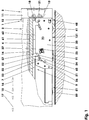
- FIGS. 1 and 2 show a sliding door (1).
- Such sliding doors (1) are used, for example, for closing cabinets, for separating rooms, etc.
- the sliding doors (1) are in an open position from an open position in which they allow access to the cabinet or in the room, in which the access is blocked and moved back.
- the drive of the sliding door (1), for example, relative to the door frame can be done by hand or by motor.
- the sliding door (1) comprises in the exemplary embodiment, a support frame (3), a door plate (14) and at least one door fitting (20).
- the support frame (3) of the sliding door (1) consists for example of four profile elements (4, 11) which delimit the door plate (14) in the form of a rectangle.
- the horizontal profile element (4) is formed on the side facing away from this profile opening (5) at least approximately U-shaped, see. FIG. 3 ,
- In the example cuboid on receiving opening (9) is arranged on the profile web (6) adjacent cylinder rod (7) with a longitudinal direction (15) oriented internal thread (8).
- the vertical profile element (11) is formed on the side facing away from the profile opening (12) as a hollow profile with approximately rectangular cross-section.
- this profile element (11) an overhead fastening screw (18) and an underlying adjusting screw (21) are arranged.
- the fastening screw (18) is screwed into the internal thread (8) of the cylinder rod (7).
- the door plate (14) is for example a rectangular plate whose width is smaller than the width of the support frame (3). It can be made of metal, wood, plastic, glass or an endermaterial. It is also conceivable to use the door plate (14), e.g. Laminate build or run it, for example, with a glass insert in a wooden frame.
- the door shield (14) may be solid or lightweight, e.g. be formed with two connected by a honeycomb core cover plates.
- the door fitting (20) is inserted into the receiving opening (9) of the horizontal profile element (4). In the exemplary embodiment, it protrudes into the profile opening (12) of the vertical profile element (11).
- the door fitting (20) comprises a housing (31), a lifting ram (61) and an acceleration and deceleration device (81).
- the FIGS. 4 to 9 show the door fitting (20) and its individual parts.
- the door fitting (20) shown in these figures is a left-hand door fitting. It is identical to a right-hand door fitting (20), with the exception of the mirror-inverted acceleration and deceleration device (81).
- the housing (31) has two side cheeks (32) arranged parallel to one another, which in the exemplary embodiment are connected to one another by means of spacer pins (34, 35).
- a roller (41) is mounted in the housing (31).
- This roller (41) has, for example, a flange (42) and an integrated roller bearing whose inner ring (43) on the one axis (35) forming the lower spacer pin (35) sits.
- two stripper brushes (48, 131) are arranged, of which in the illustration of FIGS. 1 . 3 and 4 one in front and the other behind the roller (41) is arranged.
- the single side wall (32, 33) of the housing (31) has an at least approximately rectangular contour.
- the right side cheek (32) has in the exemplary embodiment a brush receiving lug (45) and a spring receiving lug (38).
- the strip-shaped brush receiving lug (45) is arranged in the lower region of the side cheek (33). It carries a brush holder (46) with a T-slot (47), in which the frontally oriented stripper brush (48) is inserted.
- the spring receiving lug (38) is formed U-shaped. The opening points into the interior (36) of the housing (31). In this spring receiving lug (38) is a return spring (23) mounted as a restoring element (23), whose other end is mounted on the lifting tappet (61).
- each side cheek (32, 33) of the housing (31) Adjacent to its upper side (37) each side cheek (32, 33) of the housing (31) has two spaced, unilaterally open grooves (51).
- the two grooves (51) of a side wall (32; 33) are identical to one another and formed parallel to one another. Both grooves (51) have an overhead insertion area (52) and a guide area (53).
- This guide region (53) has in each case an underlying key track (54) and an overhead securing track (55).
- These two tracks (54, 55) are connected at their lower end by means of a stop (56).
- Another stop (57) is arranged at the upper end of the wedge track (54). This stop (57) is connected to the insertion region (52).
- the lifting ram (61) which is constructed largely in the form of a horizontal H in cross-section, comprises a spring receiver (67), four guide elements (65) and longitudinal webs (62) arranged in the longitudinal direction (15).
- the lifting ram (61) has a transverse receiving groove (68) in which in the exemplary embodiment a threaded insert (69) is arranged.
- the adjusting screw (21) is screwed.
- the adjusting screw (21) and the threaded insert (69) form the adjusting device (21, 69) of the door fitting (20).
- the guide elements (65) are arranged on the opposite outer sides (64) of the Hubst formulateels (61). They each have an oval cross-sectional area. In each case a guide element (65) is seated in a groove (51) of the housing (31). The longitudinal direction of the cross-sectional area of the guide elements (65) is oriented in the longitudinal direction of the respective groove (51).
- the longitudinal webs (62) are arranged on the upper side (66) of the lifting tappet (61). They are aligned with the outer sides (64) of the Hubst Congressels (61) and have a constant distance to each other. In the rear and in the front area, the longitudinal webs (62) have elevations (63). In these areas, the longitudinal webs (62) are formed as bearing webs (63). The tops of the contact webs (63) lie in a common plane.
- the acceleration and deceleration device (81) is mounted in the housing (31), for example, it is locked there. It comprises a supporting part (82) in which a cylinder-piston unit (111), an energy store (121) and a driving element (91) are arranged.
- the support member (82) has in the exemplary embodiment a guide surface (83). This comprises a parallel to the longitudinal direction (15) of the door fitting (20) oriented straight guide portion (84) and arranged for example normal thereto Holding section (85).
- the two sections (84, 85) are connected to one another by means of an arc section (86).
- the holding (85) and the arc portion (86) are part of a guide groove (87) having an expansion (88) in the end region.
- This driving element (91) engages over the supporting part (82). It has for example two sliding elements (92), a guiding and receiving element (93) and a driving area (101).
- the rod-shaped sliding elements (92) are spaced from each other and abut the guide surface (83).
- the sliding elements (92) connect the driving area (101) and the guiding and receiving element (93).
- the entrainment area (101) comprises two stop pins (102, 103) facing towards each other, e.g. arranged parallel to each other stop surfaces (104) are arranged. These are aligned, for example, normal to the tangential plane of the sliding elements (92).
- the two stop surfaces (104) define together with a bottom surface (105) a Mitauerausappelung (106).
- the entrainment region (101) has a first guide surface (94) facing the support part (82).
- the holding section (85) facing Anschlagzafen (102) is formed elastically deformable in the embodiment.
- the guiding and receiving element (93) comprises a second guide surface (95) arranged parallel to the first-mentioned guide surface (94) and a spring receptacle (96).
- the spring receiver (96) points in the direction away from the holding section (85).
- the tension spring (121) forms the energy store of the acceleration and deceleration device (81).
- the cylinder-piston unit (111) comprises a cylinder (112) and a piston (117) guided therein by means of a piston rod (115).
- the piston rod (115) has on its end facing away from the piston (117) a piston rod head (116), which is pivotally mounted in the driving element (91).
- the cylinder (112) has a closed bottom (113). Its inner wall may be cylindrical or conical.
- the cylinder inner wall has, for example, two longitudinally oriented grooves of different lengths, both of which adjoin the cylinder bottom (113). For example, the length of the short longitudinal groove is a quarter of the length of the cylinder.
- the length of the long longitudinal groove is e.g. three quarters of the length of the cylinder (112).
- the cylinder (112) is closed by means of a cylinder head cover (114) with a piston rod seal.
- the piston (117) has a piston seal (118) with a sealing lip oriented in the direction of the cylinder bottom (113).
- the piston (117) may be formed integrally with the piston rod (115) and / or with the piston seal (118).
- a brush holder (132) with the brush (131) is further arranged.
- a driver (150) is arranged on a door rail (140).
- This is in the exemplary embodiment, a symmetrical to its transverse axis component with four driving lugs (151, 152).
- Each of the two adjacent, by a notch (153) separated catch lugs (151, 152) together have a length which is slightly shorter than the distance of the stop surfaces (104) of the driving element (91).
- the acceleration and deceleration device (81) is pre-assembled.
- the piston rod (115) is inserted with the piston (117) in the cylinder (112) and this closed by means of the cylinder head cover (114).
- the cylinder-piston unit (111) with the driving element (91) in the support member (82) is inserted and secured.
- the tension spring (121) is suspended.
- the brush holder (132) is inserted with the wiper brush (131) in the support member (82).
- the acceleration and deceleration device (81) is inserted together with the roller (41) and the front brush (48) in one half of the housing (31). Now, the spacer pins (31, 35) and the second half of the housing (31) can be placed and secured.
- the first tension spring (23) on the housing (31) and on the Hubst Congressel (61) are hung.
- the lifting plunger (61) is then inserted into the housing (31) with the threaded insert (69) inserted therein, wherein the guide elements (65) engage in the grooves (51).
- the tension spring (23) pulls the lift rod (61) into the retracted rest position (24).
- the pre-assembled fitting (20) has compact dimensions. It is also conceivable to carry out the assembly of the fitting (20) in a different order.
- the fitting (20) can now be inserted into the supporting frame (3) of the sliding door (1). In this case, for example, it lies precisely in the receiving opening (9) of the horizontal profile element (4).
- a stop (89) on the support part (82) of the acceleration and deceleration device (81) prevents too far insertion of the fitting (20).
- the adjusting screw (21) is inserted and screwed into the threaded insert (69).
- the roller (41) After inserting the sliding door (1) in the door frame, the roller (41) is in the door rail (140). The two wiper brushes (48, 131) touch the door rail (140) in front of and behind the roller (41).
- the sliding door (1) is in its lowest position, cf. FIG. 10 ,
- the Hubst Congressel (61) is in the rest position (24).
- the piston (117) of the acceleration and deceleration device (81) is retracted.
- the entrainment element (91) is in its end position in the straight guide section (84).
- the energy store (121) is discharged.
- the driver (150) can be arranged on the door rail (140), for example, on the inside of the cabinet. This can be done either by means of a template or with the sliding door closed (1) by adapting to the driving element (91) in the retracted position.
- the height of the sliding door (1) can be adjusted.
- To raise the adjusting screw (21) is screwed into the thread (69).
- the Hubst Congressel (61) is tightened in the direction of the vertical profile element (11). He wanders along the Keilbahnen (54) upwards.
- the door plate (14) with the support frame (3) is raised relative to the door rail (140) and the roller (41).
- the maximum lifting height is limited by the upper stop (57) of the groove (51), cf. FIG. 11 ,
- the adjusting screw (21) can be rotated in the release direction.
- the gravity of the sliding door (1) causes together with the tension spring (23) lifting of the housing (31) relative to the lift rod (61).
- the sliding door leaf (2) lowers until the stop (56) of the grooves (51) prevents further lowering, cf. FIG. 10 ,
- the acceleration and deceleration device (81) stands, for example, in the end position described above, in which the energy store (121) is discharged.
- the driver (150) contacts the front stop pin (102) of the driving element (91) and deforms it.
- the catch lugs (151, 152) of the driver (150) jump into the Mitaueraus predominantlyung (106).
- the stop pin (102) deforms elastically back.
- the sliding door (1) is now ready for use.
- the driving element (91) When closing the sliding door (1) contacted before reaching the closed end position, the driving element (91) the driver (150). The driver (150) releases the carrier element (91) from the parking position. The energy store (121) is relieved and pulls the entrainment element (91) in the direction of the end position. The sliding door (1) is thus pulled into the closed position. At the same time, the driving element (91) moved relative to the cylinder (112) displaces the piston (117) into the cylinder (112). The sealing lip of the piston seal (118) abruptly abuts against the cylinder inner wall and seals in the cylinder interior a displacement chamber against a compensation chamber quasi hermetically. The sliding door (1) is braked.
- the piston passes over the first longitudinal groove of the cylinder inner wall, e.g. Gas is displaced from the displacement chamber into the expansion chamber along this throttle groove.
- the movement of the sliding door (1) is determined by the acceleration applied by the energy accumulator (121) and by the delay caused simultaneously by the cylinder-piston unit (111).
- the piston (117) passes over the short longitudinal groove, the deceleration rate is further reduced.
- the sliding door (1) moves slowly into its closed end position. There she stays without jerking.
- the sliding door (1) can have a further fitting (20), which is arranged on the side of the sliding door (1) facing in the opening direction (17). By adjusting the height of both fittings (20), the door leaf (2) can be aligned accurately.
- the acceleration and deceleration device (81) of the second Fittings (20) for the controlled start of the open end position of the sliding door (1) are used.
- the fitting (20) can be used with both light and heavy sliding doors (1). Due to its compact design, it is easy to install as a whole.
- the two longitudinal webs (62) surround the threaded sleeve (7) of the profile element (4) and are centered there, so that a secure system of the fitting (20) is ensured on the door profile.
- the fitting (20) is thus compatible with existing guides.
Landscapes
- Engineering & Computer Science (AREA)
- Mechanical Engineering (AREA)
- Civil Engineering (AREA)
- Structural Engineering (AREA)
- Closing And Opening Devices For Wings, And Checks For Wings (AREA)
- Power-Operated Mechanisms For Wings (AREA)
- Specific Sealing Or Ventilating Devices For Doors And Windows (AREA)
- Wing Frames And Configurations (AREA)
Description
Die Erfindung betrifft einen Türbeschlag zur Höhenverstellung einer Schiebetür zwischen einer eingefahrenen Ruhelage und einer ausgefahrenen Endlage mit einem Gehäuse, in dem mindestens eine Laufrolle gelagert ist und mit einem relativ zum Gehäuse mittels mindestens zwei Keilbahnen als Teile zueinander beabstandeter Nuten und mindestens vier in den Nuten sitzenden Führungselementen verstellbaren Hubstößel, wobei jede Keilbahn zwei Endanschläge aufweist, von denen der erste Anschlag die Ruhelage begrenzt und der zweite Anschlag die Endlage begrenzt sowie eine Schiebetür mit mindestens einem derartigen Türbeschlag.The invention relates to a door fitting for height adjustment of a sliding door between a retracted rest position and an extended end position with a housing in which at least one roller is mounted and with a relative to the housing by means of at least two splines as parts spaced grooves and at least four seated in the grooves Guide elements adjustable lift plunger, each Keilbahn having two end stops, of which the first stop limits the rest position and the second stop limits the end position and a sliding door with at least one such door fitting.
Elemente eines derartigen Türbeschlags sind aus der
Die
Der vorliegenden Erfindung liegt daher die Aufgabe zugrunde, einen problemlos zu montierenden und betriebssicheren höhenverstellbaren Türbeschlag zu entwickeln.The present invention is therefore based on the object to develop a trouble-free to install and reliable height-adjustable door fitting.
Diese Problemstellung wird mit den Merkmalen des Hauptanspruches gelöst. Dazu weist jede Keilbahn einen an eine Körpergrenzfläche und an den Endanschlag der Endlage anschließenden Einsetzbereich der einseitig offen ausgebildeten Nut auf. Ein am Gehäuse und am Hubstößel angeordnetes Rückstellelement belastet den Hubstößel relativ zum Gehäuse in Richtung der Ruhelage.This problem is solved with the features of the main claim. For this purpose, each keyway has a subsequent to a body interface and the end stop of the end position insertion of the one-sided open groove. A restoring element arranged on the housing and on the lifting ram loads the lifting ram relative to the housing in the direction of the rest position.
Weitere Einzelheiten der Erfindung ergeben sich aus den Unteransprüchen und der nachfolgenden Beschreibung schematisch dargestellter Ausführungsformen.
- Figur 1:
- Schiebetür mit Türbeschlag;
- Figur 2:
- Stirnansicht der Schiebetür;
- Figur 3:
-
Figur 2 - Figur 4:
- Unteransicht des Türbeschlags mit Mitnahmeeelement;
- Figur 5:
- Draufsicht des Türbeschlags;
- Figur 6:
- Isometrische Ansicht des Türbeschlags;
- Figur 7:
- Längsschnitt des Türbeschlags;
- Figur 8:
- Hubstößel;
- Figur 9:
- Beschleunigungs- und Verzögerungsvorrichtung;
- Figur 10:
- Türbeschlag in der Ruhelage;
- Figur 11:
- Türbeschlag in der Endlage.
- FIG. 1:
- Sliding door with door fitting;
- FIG. 2:
- Front view of the sliding door;
- FIG. 3:
-
FIG. 2 with removed vertical profile element; - FIG. 4:
- Bottom view of the door fitting with entrainment element;
- FIG. 5:
- Top view of the door fitting;
- FIG. 6:
- Isometric view of the door fitting;
- FIG. 7:
- Longitudinal section of the door fitting;
- FIG. 8:
- push member;
- FIG. 9:
- Acceleration and deceleration device;
- FIG. 10:
- Door fitting in the rest position;
- FIG. 11:
- Door fitting in the end position.
Die
Die Schiebetür (1) umfasst im Ausführungsbeispiel einen Tragrahmen (3), ein Türschild (14) und mindestens einen Tür beschlag (20).The sliding door (1) comprises in the exemplary embodiment, a support frame (3), a door plate (14) and at least one door fitting (20).
Der Tragrahmen (3) der Schiebetür (1) besteht beispielsweise aus vier Profilelementen (4, 11), die in Form eines Rechtecks das Türschild (14) begrenzen. Das einzelne Profilelement (4, 11), von denen in den
Das horizontale Profilelement (4) ist auf der dieser Profilöffnung (5) abgewandten Seite zumindest annähernd u-förmig ausgebildet, vgl.
Das vertikale Profilelement (11) ist auf der der Profil öffnung (12) abgewandten Seite als Hohlprofil mit annähernd rechteckigem Querschnitt ausgebildet. In diesem Profil element (11) sind eine obenliegende Befestigungsschraube (18) und eine untenliegende Einstellschraube (21) angeordnet. Mittels der Befestigungsschraube (18) ist das vertikale Profilelement (11) mit dem horizontalen Profilelement (4) verbunden. Hierbei ist die Befestigungsschraube (18) in das Innengewinde (8) des Zylinderstabs (7) eingeschraubt.The vertical profile element (11) is formed on the side facing away from the profile opening (12) as a hollow profile with approximately rectangular cross-section. In this profile element (11) an overhead fastening screw (18) and an underlying adjusting screw (21) are arranged. By means of the fastening screw (18), the vertical profile element (11) with the horizontal profile element (4) is connected. Here, the fastening screw (18) is screwed into the internal thread (8) of the cylinder rod (7).
Das Türschild (14) ist beispielsweise eine quaderförmige Platte, deren Breite geringer ist als die Breite des Tragrahmens (3). Es kann aus Metall, Holz, Kunststoff, Glas oder einem enderen Werkstoff hergestellt sein. Auch ist es denkbar, das Türschild (14) z.B. laminatförmig aufzubauen oder es beispielsweise mit einem Glaseinsatz in einem Holzrahmen auszuführen. Das Türschild (14) kann massiv oder in Leichtbauweise, z.B. mit zwei mittels eines wabeförmigen Kerns verbundenen Deckplatten, ausgebildet sein.The door plate (14) is for example a rectangular plate whose width is smaller than the width of the support frame (3). It can be made of metal, wood, plastic, glass or an endermaterial. It is also conceivable to use the door plate (14), e.g. Laminate build or run it, for example, with a glass insert in a wooden frame. The door shield (14) may be solid or lightweight, e.g. be formed with two connected by a honeycomb core cover plates.
Der Türbeschlag (20) ist in die Aufnahmeöffnung (9) des horizontalen Profilelements (4) eingesetzt. Im Ausführungsbeispiel ragt er in die Profilöffnung (12) des vertikalen Profilelements (11). Der Türbeschlag (20) umfasst ein Gehäuse (31), einen Hubstößel (61) und eine Beschleunigungs- und Verzögerungsvorrichtung (81). Die
Das Gehäuse (31) hat zwei parallel zueinander angeordnete Seitenwangen (32), die im Ausführungsbeispiel mittels Abstandsstiften (34, 35) miteinander verbunden sind. Im unteren Bereich ist im Gehäuse (31) eine Laufrolle (41) gelagert. Diese Laufrolle (41) hat beispielsweise einen Spurkranz (42) und ein integriertes Wälzlager, dessen Innenring (43) auf dem einen Achse (35) bildenden unteren Abstandsstift (35) sitzt. An der Unterseite des Gehäuses (31) sind zwei Abstreiferbürsten (48, 131) angeordnet, von denen in der Darstellung der
Die einzelne Seitenwange (32, 33) des Gehäuses (31) hat eine zumindest annähernd rechteckige Kontur. Die rechte Seitenwange (32) weist im Ausführungsbeispiel eine Bürstenaufnahmelasche (45) und eine Federaufnahmelasche (38) auf.The single side wall (32, 33) of the housing (31) has an at least approximately rectangular contour. The right side cheek (32) has in the exemplary embodiment a brush receiving lug (45) and a spring receiving lug (38).
Die streifenförmig ausgebildete Bürstenaufnahmelasche (45) ist im unteren Bereich der Seitenwange (33) angeordnet. Sie trägt einen Bürstenträger (46) mit einer T-Nut (47), in der die stirnseitig orientierte Abstreifbürste (48) eingesetzt ist.The strip-shaped brush receiving lug (45) is arranged in the lower region of the side cheek (33). It carries a brush holder (46) with a T-slot (47), in which the frontally oriented stripper brush (48) is inserted.
Die Federaufnahmelasche (38) ist U-fömig ausgebildet. Die Öffnung zeigt in den Innenraum (36) des Gehäuses (31). In dieser Federaufnahmelasche (38) ist als Rückstellelement (23) eine Zugfeder (23) eingehängt, deren anderes Ende am Hubstößel (61) gelagert ist.The spring receiving lug (38) is formed U-shaped. The opening points into the interior (36) of the housing (31). In this spring receiving lug (38) is a return spring (23) mounted as a restoring element (23), whose other end is mounted on the lifting tappet (61).
Angrenzend an ihre Oberseite (37) hat jede Seitenwange (32, 33) des Gehäuses (31) zwei einander beabstandete, einseitig offene Nuten (51). Die beiden Nuten (51) einer Seitenwange (32; 33) sind identisch zueinander und parallel zueinander ausgebildet. Beide Nuten (51) haben einen obenliegenden Einsetzbereich (52) und einen Führungsbereich (53). Dieser Führungsbereich (53) hat jeweils eine untenliegende Keilbahn (54) und eine obenliegende Sicherungsbahn (55). Diese beiden Bahnen (54, 55) sind an ihrem unteren Ende mittels eines Anschlags (56) verbunden. Ein weiterer Anschlag (57) ist am oberen Ende der Keilbahn (54) angeordnet. Dieser Anschlag (57) ist mit dem Einsetzbereich (52) verbunden.Adjacent to its upper side (37) each side cheek (32, 33) of the housing (31) has two spaced, unilaterally open grooves (51). The two grooves (51) of a side wall (32; 33) are identical to one another and formed parallel to one another. Both grooves (51) have an overhead insertion area (52) and a guide area (53). This guide region (53) has in each case an underlying key track (54) and an overhead securing track (55). These two tracks (54, 55) are connected at their lower end by means of a stop (56). Another stop (57) is arranged at the upper end of the wedge track (54). This stop (57) is connected to the insertion region (52).
In den Nuten (51) ist der Hubstößel (61) geführt. Der im Querschnitt weitgehend in Form eines liegenden H aufgebaute Hubstößel (61) umfasst eine Federaufnahme (67), vier Führungselemente (65) sowie in Längsrichtung (15) angeordnete Längsstege (62). An seinem vorderen Ende hat der beispielsweise aus Kunststoff hergestellte Hubstößel (61) eine querliegende Aufnahmenut (68), in der im Ausführungsbeispiel ein Gewindeeinsatz (69) angeordnet ist. In diesen Gewindeeinsatz (69) ist die Einstellschraube (21) eingeschraubt. Die Einstellschraube (21) und der Gewindeeinsatz (69) bilden die Einstellvorrichtung (21, 69) des Türbeschlags (20).In the grooves (51) of the lift rod (61) is guided. The lifting ram (61), which is constructed largely in the form of a horizontal H in cross-section, comprises a spring receiver (67), four guide elements (65) and longitudinal webs (62) arranged in the longitudinal direction (15). At the front end of the example has Plastic-made lifting ram (61) has a transverse receiving groove (68) in which in the exemplary embodiment a threaded insert (69) is arranged. In this threaded insert (69), the adjusting screw (21) is screwed. The adjusting screw (21) and the threaded insert (69) form the adjusting device (21, 69) of the door fitting (20).
Die Führungselemente (65) sind auf den einander gegenüberliegenden Außenseiten (64) des Hubstößels (61) angeordnet. Sie haben jeweils eine ovale Querschnittsfläche. Jeweils ein Führungselement (65) sitzt in einer Nut (51) des Gehäuses (31). Die Längsrichtung der Querschnittsfläche der Führungselemente (65) ist in der Längsrichtung der jeweiligen Nut (51) orientiert.The guide elements (65) are arranged on the opposite outer sides (64) of the Hubstößels (61). They each have an oval cross-sectional area. In each case a guide element (65) is seated in a groove (51) of the housing (31). The longitudinal direction of the cross-sectional area of the guide elements (65) is oriented in the longitudinal direction of the respective groove (51).
Die Längsstege (62) sind an der Oberseite (66) des Hubstößels (61) angeordnet. Sie fluchten mit den Außenseiten (64) des Hubstößels (61) und haben zueinander einen konstanten Abstand. Im hinteren und im vorderen Bereich weisen die Längsstege (62) Erhöhungen (63) auf. In diesen Bereichen sind die Längsstege (62) als Anlagestege (63) ausgebildet. Die Oberseiten der Anlagestege (63) liegen in einer gemeinsamen Ebene.The longitudinal webs (62) are arranged on the upper side (66) of the lifting tappet (61). They are aligned with the outer sides (64) of the Hubstößels (61) and have a constant distance to each other. In the rear and in the front area, the longitudinal webs (62) have elevations (63). In these areas, the longitudinal webs (62) are formed as bearing webs (63). The tops of the contact webs (63) lie in a common plane.
Die Beschleunigungs- und Verzögerungsvorrichtung (81) ist im Gehäuse (31) befestigt, beispielsweise ist sie dort verrastet. Sie umfasst ein Tragteil (82), in dem eine Zylinder-Kolben-Einheit (111), ein Energiespeicher (121) und ein Mitnahmeelement (91) angeordnet sind.The acceleration and deceleration device (81) is mounted in the housing (31), for example, it is locked there. It comprises a supporting part (82) in which a cylinder-piston unit (111), an energy store (121) and a driving element (91) are arranged.
Das Tragteil (82) weist im Ausführungsbeispiel eine Führungsfläche (83) auf. Diese umfasst einen parallel zur Längsrichtung (15) des Türbeschlags (20) orientierten geraden Führungsabschnitt (84) und einen z.B. normal hierzu angeordneten Halteabschnitt (85). Die beiden Abschnitte (84, 85) sind mittels eines Bogenabschnitts (86) miteinander verbunden. Der Halte- (85) und der Bogenabschnitt (86) sind Teil einer Führungsnut (87), die im Endbereich eine Aufweitung (88) aufweist.The support member (82) has in the exemplary embodiment a guide surface (83). This comprises a parallel to the longitudinal direction (15) of the door fitting (20) oriented straight guide portion (84) and arranged for example normal thereto Holding section (85). The two sections (84, 85) are connected to one another by means of an arc section (86). The holding (85) and the arc portion (86) are part of a guide groove (87) having an expansion (88) in the end region.
Entlang der Führungsfläche (83) ist das Mitnahmeelement (91) verfahrbar. Dieses Mitnahmeelement (91) übergreift das Tragteil (82). Es hat beispielsweise zwei Gleitelemente (92), ein Führungs- und Aufnahmeelement (93) und einen Mitnahmebereich (101).Along the guide surface (83) the entrainment element (91) is movable. This driving element (91) engages over the supporting part (82). It has for example two sliding elements (92), a guiding and receiving element (93) and a driving area (101).
Die stabförmig ausgebildeten Gleitelemente (92) sind voneinander beabstandet und liegen an der Führungsfläche (83) an. Die Gleitelemente (92) verbinden den Mitnahmebereich (101) und das Führungs- und Aufnahmeelement (93).The rod-shaped sliding elements (92) are spaced from each other and abut the guide surface (83). The sliding elements (92) connect the driving area (101) and the guiding and receiving element (93).
Der Mitnahmebereich (101) umfasst zwei Anschlagzapfen (102, 103), an den einander zugewandte, z.B. parallel zueinander angeordnete Anschlagflächen (104) angeordnet sind. Diese sind beispielsweise normal zur Tangentialebene der Gleitelemente (92) ausgerichtet. Die beiden Anschlagflächen (104) begrenzen zusammen mit einer Bodenfläche (105) eine Mitnehmerausnehmung (106). Der Mitnahmebereich (101) hat eine dem Tragteil (82) zugewandte erste Führungsfläche (94). Der dem Halteabschnitt (85) zugewandte Anschlagzafen (102) ist im Ausführungsbeispiel elastisch verformbar ausgebildet.The entrainment area (101) comprises two stop pins (102, 103) facing towards each other, e.g. arranged parallel to each other stop surfaces (104) are arranged. These are aligned, for example, normal to the tangential plane of the sliding elements (92). The two stop surfaces (104) define together with a bottom surface (105) a Mitnehmerausnehmung (106). The entrainment region (101) has a first guide surface (94) facing the support part (82). The holding section (85) facing Anschlagzafen (102) is formed elastically deformable in the embodiment.
Das Führungs- und Aufnahmeelement (93) umfasst eine zu der erstgenannten Führungsfläche (94) parallel angeordnete zweite Führungsfläche (95) sowie eine Federaufnahme (96). Die Federaufnahme (96) zeigt in die dem Halteabschnitt (85) abgewandte Richtung.The guiding and receiving element (93) comprises a second guide surface (95) arranged parallel to the first-mentioned guide surface (94) and a spring receptacle (96). The spring receiver (96) points in the direction away from the holding section (85).
In der Federaufnahme (96) ist ein Ende einer Zugfeder (121) eingehängt. Das andere Ende der Zugfeder (121) ist im Tragteil (82) gelagert. Im Ausführungsbeispiel bildet die Zugfeder (121) den Energiespeicher der Beschleunigungs- und Verzögerungsvorrichtung (81).In the spring receptacle (96) one end of a tension spring (121) is mounted. The other end of the tension spring (121) is mounted in the support part (82). In the exemplary embodiment, the tension spring (121) forms the energy store of the acceleration and deceleration device (81).
Die Zylinder-Kolben-Einheit (111) umfasst einen Zylinder (112) und einen in diesem mittels einer Kolbenstange (115) geführten Kolben (117). Die Kolbenstange (115) weist an ihrer dem Kolben (117) abgewandten Stirnseite einen Kolbenstangenkopf (116) auf, der im Mitnahmeeelement (91) schwenkbar gelagert ist.The cylinder-piston unit (111) comprises a cylinder (112) and a piston (117) guided therein by means of a piston rod (115). The piston rod (115) has on its end facing away from the piston (117) a piston rod head (116), which is pivotally mounted in the driving element (91).
Der Zylinder (112) hat einen geschlossenen Boden (113). Seine Innenwandung kann zylindrisch oder konisch ausgebildet sein. Die Zylinderinnenwandung hat beispielsweise zwei in Längsrichtung orientierte Nuten unterschiedlicher Länge, die beide an den Zylinderboden (113) angrenzen. Beispielsweise beträgt die Länge der kurzen Längsnut ein Viertel der Länge des Zylinders. Die Länge der langen Längsnut beträgt z.B. drei Viertel der Länge des Zylinders (112). Am kolbenstangenseitigen Ende ist der Zylinder (112) mittels eines Zylinderkopfdeckels (114) mit einer Kolbenstangendichtung verschlossen.The cylinder (112) has a closed bottom (113). Its inner wall may be cylindrical or conical. The cylinder inner wall has, for example, two longitudinally oriented grooves of different lengths, both of which adjoin the cylinder bottom (113). For example, the length of the short longitudinal groove is a quarter of the length of the cylinder. The length of the long longitudinal groove is e.g. three quarters of the length of the cylinder (112). At the piston rod end, the cylinder (112) is closed by means of a cylinder head cover (114) with a piston rod seal.
Der Kolben (117) hat im Ausführungsbeispiel eine Kolbendichtung (118) mit einer in Richtung des Zylinderbodens (113) orientierten Dichtlippe. Der Kolben (117) kann einteilig mit der Kolbenstange (115) und/oder mit der Kolbendichtung (118) ausgebildet sein.In the exemplary embodiment, the piston (117) has a piston seal (118) with a sealing lip oriented in the direction of the cylinder bottom (113). The piston (117) may be formed integrally with the piston rod (115) and / or with the piston seal (118).
An der Beschleunigungs- und Verzögerungsvorrichtung (81) ist weiterhin ein Bürstenträger (132) mit der Bürste (131) angeordnet.At the acceleration and deceleration device (81), a brush holder (132) with the brush (131) is further arranged.
An einer Türschiene (140) ist ein Mitnehmer (150) angeordnet. Dies ist im Ausführungsbeispiel ein zu seiner Querachse symmetrisches Bauteil mit vier Mitnahmenasen (151, 152). Jeweils die zwei benachbarten, durch eine Kerbe (153) getrennten Mitnahmenasen (151, 152) haben zusammen eine Länge, die geringfügig kürzer ist als der Abstand der Anschlagflächen (104) des Mitnahmeelements (91).On a door rail (140) a driver (150) is arranged. This is in the exemplary embodiment, a symmetrical to its transverse axis component with four driving lugs (151, 152). Each of the two adjacent, by a notch (153) separated catch lugs (151, 152) together have a length which is slightly shorter than the distance of the stop surfaces (104) of the driving element (91).
Bei der Montage wird beispielsweise zunächst die Beschleunigungs- und Verzögerungsvorrichtung (81) vormontiert. Hierbei wird die Kolbenstange (115) mit dem Kolben (117) in den Zylinder (112) eingesetzt und dieser mittels des Zylinderkopfdeckels (114) verschlossen. Anschließend wird die Zylinder-Kolbeneinheit (111) mit dem Mitnahmeelement (91) in das Tragteil (82) eingesetzt und gesichert. Am Mitnahmeelement (91) und am Tragteil (82) wird die Zugfeder (121) eingehängt. Weiterhin wird der Bürstenträger (132) mit der Abstreiferbürste (131) in das Tragteil (82) eingeschoben.During assembly, for example, first the acceleration and deceleration device (81) is pre-assembled. Here, the piston rod (115) is inserted with the piston (117) in the cylinder (112) and this closed by means of the cylinder head cover (114). Subsequently, the cylinder-piston unit (111) with the driving element (91) in the support member (82) is inserted and secured. At the driving element (91) and the support member (82) the tension spring (121) is suspended. Furthermore, the brush holder (132) is inserted with the wiper brush (131) in the support member (82).
Die Beschleunigungs- und Verzögerungsvorrichtung (81) wird zusammen mit der Laufrolle (41) und der vorderen Bürste (48) in die eine Hälfte des Gehäuses (31) eingesetzt. Nun können die Abstandsstifte (31, 35) und die zweite Hälfte des Gehäuses (31) aufgesetzt und gesichert werden.The acceleration and deceleration device (81) is inserted together with the roller (41) and the front brush (48) in one half of the housing (31). Now, the spacer pins (31, 35) and the second half of the housing (31) can be placed and secured.
In einem nächsten Schritt kann die erste Zugfeder (23) am Gehäuse (31) und am Hubstößel (61) eingehängt werden. Der Hubstößel (61) wird dann mit dem in diesen eingesetzten Gewindeeinsatz (69) in das Gehäuse (31) eingeschoben, wobei die Führungselemente (65) in die Nuten (51) eingreifen. Die Zugfeder (23) zieht den Hubstößel (61) in die eingefahrene Ruhelage (24). Der so vormontierte Beschlag (20) hat kompakte Abmessungen. Es ist auch denkbar, die Montage des Beschlags (20) in anderer Reihenfolge durchzuführen.In a next step, the first tension spring (23) on the housing (31) and on the Hubstößel (61) are hung. The lifting plunger (61) is then inserted into the housing (31) with the threaded insert (69) inserted therein, wherein the guide elements (65) engage in the grooves (51). The tension spring (23) pulls the lift rod (61) into the retracted rest position (24). The pre-assembled fitting (20) has compact dimensions. It is also conceivable to carry out the assembly of the fitting (20) in a different order.
Der Beschlag (20) kann nun in den Tragrahmen (3) der Schiebetür (1) eingesetzt werden. Hierbei liegt er beispielsweise passgenau in der Aufnahmeöffnung (9) des horizontalen Profilelements (4). Ein Anschlag (89) am Tragteil (82) der Beschleunigungs- und Verzögerungsvorrichtung (81) verhindert ein zu weites Einschieben des Beschlags (20). Von der Stirnseite des vertikalen Profilelements (11) wird die Einstellschraube (21) eingesetzt und in den Gewindeeinsatz (69) eingedreht.The fitting (20) can now be inserted into the supporting frame (3) of the sliding door (1). In this case, for example, it lies precisely in the receiving opening (9) of the horizontal profile element (4). A stop (89) on the support part (82) of the acceleration and deceleration device (81) prevents too far insertion of the fitting (20). From the front side of the vertical profile element (11), the adjusting screw (21) is inserted and screwed into the threaded insert (69).
Nach dem Einsetzen der Schiebetür (1) in den Türrahmen steht die Laufrolle (41) in der Türschiene (140). Die beiden Abstreiferbürsten (48, 131) berühren die Türschiene (140) vor und hinter der Laufrolle (41). Die Schiebetür (1) steht in ihrer untersten Position, vgl.
An der Türschiene (140) kann beispielsweise an der Innenseite des Schrankes der Mitnehmer (150) angeordnet werden. Dies kann entweder mittels einer Schablone oder bei geschlossener Schiebetür (1) durch Anpassen an das Mitnahmeelement (91) in der eingefahrenen Stellung erfolgen.On the door rail (140), for example, on the inside of the cabinet, the driver (150) can be arranged. This can be done either by means of a template or with the sliding door closed (1) by adapting to the driving element (91) in the retracted position.
Nun kann die Höhe der Schiebetür (1) eingestellt werden. Zum Anheben wird die Einstellschraube (21) in das Gewinde (69) eingedreht. Der Hubstößel (61) wird in Richtung des vertikalen Profilelements (11) angezogen. Er wandert entlang der Keilbahnen (54) nach oben. Das Türschild (14) mit dem Tragrahmen (3) wird relativ zur Türschiene (140) und der Laufrolle (41) angehoben. Die maximale Hubhöhe ist durch den oberen Anschlag (57) der Nut (51) begrenzt, vgl.
Zum Absenken der Schiebetür (1) kann die Einstellschraube (21) in die Löserichtung gedreht werden. Die Schwerkraft der Schiebetür (1) bewirkt zusammen mit der Zugfeder (23) ein Anheben des Gehäuses (31) relativ zum Hubstößel (61). Das Schiebetürblatt (2) senkt sich ab, bis der Anschlag (56) der Nuten (51) ein weiteres Absenken verhindert, vgl.
Vor dem erstmaligen Schließen der Schiebetür (1) steht die Beschleunigungs- und Verzögerungsvorrichtung (81) beispielsweise in der oben beschriebenen Endposition, bei der der Energiespeicher (121) entladen ist. Beim erstmaligen Schließen der Schiebetür (1) kontaktiert der Mitnehmer (150) den vorderen Anschlagzapfen (102) des Mitnahmeelements (91) und verformt diesen. Die Mitnahmenasen (151, 152) des Mitnehmers (150) springen in die Mitnehmerausnehmung (106). Der Anschlagzapfen (102) verformt sich elastisch zurück. Die Schiebetür (1) ist nun einsatzbereit.Before the sliding door (1) is closed for the first time, the acceleration and deceleration device (81) stands, for example, in the end position described above, in which the energy store (121) is discharged. When first closing the sliding door (1), the driver (150) contacts the front stop pin (102) of the driving element (91) and deforms it. The catch lugs (151, 152) of the driver (150) jump into the Mitnehmerausnehmung (106). The stop pin (102) deforms elastically back. The sliding door (1) is now ready for use.
Beim manuellen oder motorischen Öffnen der Schiebetür (1) aus der geschlossenen Stellung zieht der Mitnehmer (150) das Mitnahmeelement (91) aus der Endposition entlang der Führungsfläche (83) in Richtung einer Parkposition. Der Energiespeicher (121) wird geladen. Sobald das in Öffnungsrichtung (17) vordere Gleitelement (92) die Führungsnut (87) erreicht, kippt das Mitnahmeelement (91) unter der Wirkung der Feder (121) ab. Es liegt nun in einer kraft- und oder formschlüssig verriegelten Parkposition. Beim weiteren Öffnen der Schiebetür (1) löst sich das Mitnahmeelement (91) vom Mitnehmer (150). Das Mitnahmeelement (91) verbleibt in der Parkposition. Die Schiebetür (1) kann nun weiter geöffnet werden.When manual or motorized opening of the sliding door (1) from the closed position of the driver (150) pulls the driving element (91) from the end position along the guide surface (83) in the direction of a parking position. The energy store (121) is loaded. As soon as the front sliding element (92) in the opening direction (17) reaches the guide groove (87), the driving element (91) tilts under the action of the spring (121). It is now in a locked and positively locked parking position. Upon further opening of the sliding door (1), the entrainment element (91) releases from the driver (150). The entrainment element (91) remains in the parking position. The sliding door (1) can now be opened further.
Beim Schließen der Schiebetür (1) kontaktiert vor dem Erreichen der geschlossenen Endlage das Mitnahmeelement (91) den Mitnehmer (150). Der Mitnehmer (150) löst das Mitnahmeelement (91) aus der Parkposition. Der Energiespeicher (121) wird entlastet und zieht das Mitnahmeelement (91) in Richtung der Endposition. Die Schiebetür (1) wird damit in die geschlossene Stellung gezogen. Gleichzeitig verschiebt das relativ zum Zylinder (112) bewegte Mitnahmeelement (91) den Kolben (117) in den Zylinder (112) hinein. Die Dichtlippe der Kolbendichtung (118) legt sich schlagartig an die Zylinderinnenwandung an und dichtet im Zylinderinnenraum einen Verdrängungsraum gegen einen Ausgleichsraum quasi hermetisch ab. Die Schiebetür (1) wird abgebremst. Sobald beim weiteren Schließen der Schiebetür (1) der Kolben die erste Längsnut der Zylinderinnenwandung überfährt, wird z.B. Gas entlang dieser Drosselnut aus dem Verdrängungsraum in den Ausgleichsraum verdrängt. Die Bewegung der Schiebetür (1) wird durch die mittels des Energiespeichers (121) aufgebrachte Beschleunigung und durch die gleichzeitig mittels der Zylinder-Kolben-Einheit (111) bewirkte Verzögerung bestimmt. Sobald der Kolben (117) die kurze Längsnut überfährt, wird die Verzögerungsrate weiter verringert. Die Schiebetür (1) verfährt langsam in ihre geschlossene Endlage. Dort bleibt sie ruckfrei stehen.When closing the sliding door (1) contacted before reaching the closed end position, the driving element (91) the driver (150). The driver (150) releases the carrier element (91) from the parking position. The energy store (121) is relieved and pulls the entrainment element (91) in the direction of the end position. The sliding door (1) is thus pulled into the closed position. At the same time, the driving element (91) moved relative to the cylinder (112) displaces the piston (117) into the cylinder (112). The sealing lip of the piston seal (118) abruptly abuts against the cylinder inner wall and seals in the cylinder interior a displacement chamber against a compensation chamber quasi hermetically. The sliding door (1) is braked. As soon as the further closing of the sliding door (1), the piston passes over the first longitudinal groove of the cylinder inner wall, e.g. Gas is displaced from the displacement chamber into the expansion chamber along this throttle groove. The movement of the sliding door (1) is determined by the acceleration applied by the energy accumulator (121) and by the delay caused simultaneously by the cylinder-piston unit (111). As soon as the piston (117) passes over the short longitudinal groove, the deceleration rate is further reduced. The sliding door (1) moves slowly into its closed end position. There she stays without jerking.
Die Schiebetür (1) kann einen weiteren Beschlag (20) aufweisen, der an der in die Öffnungsrichtung (17) zeigenden Seite der Schiebetür (1) angeordnet ist. Durch Höheneinstellung beider Beschläge (20) kann das Türblatt (2) genau ausgerichtet werden. Bei einer derartigen Anordnung kann die Beschleunigungs- und Verzögerungsvorrichtung (81) des zweiten Beschlags (20) zum gesteuerten Anfahren der geöffneten Endlage der Schiebetür (1) eingesetzt werden.The sliding door (1) can have a further fitting (20), which is arranged on the side of the sliding door (1) facing in the opening direction (17). By adjusting the height of both fittings (20), the door leaf (2) can be aligned accurately. In such an arrangement, the acceleration and deceleration device (81) of the second Fittings (20) for the controlled start of the open end position of the sliding door (1) are used.
Der Beschlag (20) kann sowohl bei leichten als auch bei schweren Schiebetüren (1) eingesetzt werden. Aufgrund seiner kompakten Bauweise ist er als Ganzes problemlos zu montieren. Die beiden Längsstege (62) umgreifen die Gewindehülse (7) des Profilelements (4) und werden dort zentriert, sodass eine sichere Anlage des Beschlags (20) am Türprofil gewährleistet ist. Der Beschlag (20) ist damit kompatibel zu bestehenden Führungen.The fitting (20) can be used with both light and heavy sliding doors (1). Due to its compact design, it is easy to install as a whole. The two longitudinal webs (62) surround the threaded sleeve (7) of the profile element (4) and are centered there, so that a secure system of the fitting (20) is ensured on the door profile. The fitting (20) is thus compatible with existing guides.
Auch Kombinationen der einzelnen Ausführungsbeispiele sind denkbar.Combinations of the individual embodiments are conceivable.
- 11
- Schiebetürsliding door
- 22
- Türblattdoor leaf
- 33
- Tragrahmensupporting frame
- 44
- Profilelement, horizontalProfile element, horizontal
- 55
- Profilöffnung von (4)Profile opening of (4)
- 66
- Profilstegprofile web
- 77
- Zylinderstab, GewindehülseCylinder rod, threaded sleeve
- 88th
- Innengewindeinner thread
- 99
- Aufnahmeöffnungreceiving opening
- 1111
- Profilelement, vertikalProfile element, vertical
- 1212
- Profilöffnung von (11)Profile opening of (11)
- 1313
- Verstellelement-AnlageflächeAdjusting bearing surface
- 1414
- Türschildnameplate
- 1515
- Längsrichtunglongitudinal direction
- 1616
- Schließrichtungclosing direction
- 1717
- Öffnungsrichtungopening direction
- 1818
- Befestigungsschraubefixing screw
- 2020
- Türbeschlagdoor fittings
- 2121
- Einstellschraube, EinstellvorrichtungAdjusting screw, adjusting device
- 2323
- Rückstellelement, erste ZugfederReset element, first tension spring
- 2424
- Endlage, eingefahren, RuhelageEnd position, retracted, rest position
- 3131
- Gehäusecasing
- 3232
- Seitenwange, rechtsSidewall, right
- 3333
- Seitenwange, linksSidewall, left
- 3434
- Abstandsstiftespacer pins
- 3535
- Abstandsstift, AchseSpacer pin, axle
- 3636
- Innenraum von (31)Interior of (31)
- 3737
- Oberseite von (32, 33), KörpergrenzflächeTop of (32, 33), body interface
- 3838
- FederaufnahmelascheSpring receiving tab
- 4141
- Laufrollecaster
- 4242
- Spurkranzflange
- 4343
- Innenringinner ring
- 4545
- BürstenaufnahmelascheBrush record tab
- 4646
- Bürstenträgerbrush carrier
- 4747
- T-NutT-slot
- 4848
- Abstreiferbürstewiper brush
- 5151
- Nutengroove
- 5252
- Einsetzbereichinsertion region
- 5353
- Führungsbereichguide region
- 5454
- Keilbahnkeyway
- 5555
- Sicherungsbahnsecurement web
- 5656
- Anschlagattack
- 5757
- Anschlag, obere HublageStop, upper stroke position
- 6161
- Hubstößellift tappet
- 6262
- Längsstegelongitudinal webs
- 6363
- Erhöhungen, AnlagestegeElevations, contact strips
- 6464
- Außenseitenoutsides
- 6565
- Führungselementeguide elements
- 6666
- Oberseitetop
- 6767
- Federaufnahmespring mount
- 6868
- Aufnahmenutreceiving groove
- 6969
- Gewindeeinsatz, EinstellvorrichtungThreaded insert, adjustment device
- 8181
- Beschleunigungs- und VerzögerungsvorrichtungAcceleration and deceleration device
- 8282
- Tragteilsupporting part
- 8383
- Führungsflächeguide surface
- 8484
- Führungsabschnittguide section
- 8585
- Halteabschnittholding section
- 8686
- Bogenabschnittarc section
- 8787
- Führungsnutguide
- 8888
- Aufweitungwidening
- 8989
- Anschlagattack
- 9191
- Mitnahmeelementdriving element
- 9292
- GleitelementeSliding elements
- 9393
- Führungs- und AufnahmeelementGuiding and receiving element
- 9494
- erste Führungsflächefirst guide surface
- 9595
- zweite Führungsflächesecond guide surface
- 9696
- Federaufnahmespring mount
- 101101
- Mitnahmebereichdriving region
- 102102
- Anschlagzapfen, elastisch verformbarStop pin, elastically deformable
- 103103
- Anschlagzapfenstop pin
- 104104
- Anschlagflächenstop surfaces
- 105105
- Bodenflächefloor area
- 106106
- Mitnehmerausnehmungdriver recess
- 111111
- Zylinder-Kolben-EinheitCylinder-piston unit
- 112112
- Zylindercylinder
- 113113
- Boden von (112)Bottom of (112)
- 114114
- ZylinderkopfdeckelCylinder head cover
- 115115
- Kolbenstangepiston rod
- 116116
- KolbenstangenkopfPiston rod head
- 117117
- Kolbenpiston
- 118118
- Kolbendichtungpiston seal
- 121121
- Energiespeicher, ZugfederEnergy storage, tension spring
- 131131
- Abstreiferbürstewiper brush
- 132132
- Bürstenträgerbrush carrier
- 140140
- Türschienedoor rail
- 150150
- Mitnehmertakeaway
- 151151
- Mitnahmenasenimpact dogs
- 152152
- Mitnahmenasenimpact dogs
- 153153
- Kerbescore
Claims (9)
- Door accessory mechanism (20) for adjusting the height of a sliding door (1) between a retracted rest position (24) and an extended end position, comprising a housing (31) having two sidewalls (32, 33) disposed in a mutually parallel relationship and mounting at least one roller (41) adjustable relative to the housing (31) by means of a pair of wedge tracks (54) provided in the side walls (32, 33) as parts of spaced part grooves (51) and at least four guide elements (65) disposed in the grooves (51), with each groove (51) having a guide element (65) therein, and with each wedge track (54) comprising two end stops (56, 57), the first one (56) of which delimits said rest position and the second (57) of which delimits the end position,
characterized by- each wedge track (54) comprising a insertion area (52) of the groove (51), which insertion area adjoins a body limit surface (37) and the end position end stop (57), said groove (51) configured to be open on one side thereof, and- a return element (23) connected to the housing (31) and to the lift plunger (61) provided to load the lift plunger (61) relative to the housing (31) in a direction towards the rest position (24),- with the return element (23) being a draw spring connected to the housing and to the lift plunger. - Door accessory mechanism (20) as claimed in claim 1, characterized by comprising adjusting means (21, 69) with an adjusting element (21), with a tension load acting on the adjusting element (21) to lift the lift plunger (61) relative to the housing (31).
- Door accessory mechanism (20) as claimed in claim 1, characterized by comprising an accelerating and retarding unit (81).
- Door accessory mechanism (20) as claimed in claim 1, characterized in that the lift plunger (61) comprises two longitudinal web elements (62).
- Door accessory mechanism (20) as claimed in claim 1, characterized in that the guide elements (65) have an oval cross section area.
- Door accessory mechanism (20) as claimed in claim 1, characterized in that the wedge tracks (54) are provided in the housing (31) and the guide elements (65) are provided in the lift plunger (61).
- Sliding door (1) comprising at least one door accessory mechanism (20) as claimed in claim 1.
- Sliding door (1) as claimed in claim 7, characterized in that the lift plunger (61) has longitudinal web elements (62) encompassing a threaded sleeve (7) of a supporting frame (3) of the sliding door (1).
- Sliding door (1) as claimed in claim 7, characterized by a supporting frame (3) having thereon an engagement surface (13) for an adjusting element.
Priority Applications (1)
| Application Number | Priority Date | Filing Date | Title |
|---|---|---|---|
| PL16000623T PL3070243T3 (en) | 2015-03-17 | 2016-03-16 | Door fitting for height adjustment of sliding doors |
Applications Claiming Priority (1)
| Application Number | Priority Date | Filing Date | Title |
|---|---|---|---|
| DE102015003413.8A DE102015003413B3 (en) | 2015-03-17 | 2015-03-17 | Door fitting for height adjustment of sliding doors |
Publications (2)
| Publication Number | Publication Date |
|---|---|
| EP3070243A1 EP3070243A1 (en) | 2016-09-21 |
| EP3070243B1 true EP3070243B1 (en) | 2019-02-27 |
Family
ID=54866433
Family Applications (1)
| Application Number | Title | Priority Date | Filing Date |
|---|---|---|---|
| EP16000623.5A Not-in-force EP3070243B1 (en) | 2015-03-17 | 2016-03-16 | Door fitting for height adjustment of sliding doors |
Country Status (6)
| Country | Link |
|---|---|
| US (1) | US9605461B2 (en) |
| EP (1) | EP3070243B1 (en) |
| CN (1) | CN105986719B (en) |
| DE (1) | DE102015003413B3 (en) |
| ES (1) | ES2727535T3 (en) |
| PL (1) | PL3070243T3 (en) |
Families Citing this family (11)
| Publication number | Priority date | Publication date | Assignee | Title |
|---|---|---|---|---|
| DE102015003424B3 (en) * | 2015-03-17 | 2016-07-07 | Günther Zimmer | Low noise feeder and sliding door assembly |
| DE102015003415B3 (en) * | 2015-03-17 | 2016-02-25 | Günther Zimmer | Acceleration and deceleration device with low-noise movement |
| CA2921440A1 (en) * | 2015-07-29 | 2017-01-29 | Assa Abloy New Zealand Limited | A closure mechanism |
| BE1023551B1 (en) * | 2015-10-30 | 2017-05-02 | Renson Sunprotection Screens N.V. | SCREEN DEVICE |
| DE102016212793C5 (en) * | 2016-07-13 | 2023-01-05 | Roto Frank Ag | Fitting arrangement with a lifting device |
| US10982477B2 (en) * | 2017-06-09 | 2021-04-20 | Endura Products, Llc | Sliding door unit and components for the same |
| JP7039271B2 (en) * | 2017-12-04 | 2022-03-22 | 株式会社Lixil | Door car |
| EP3969709B1 (en) * | 2019-06-11 | 2024-03-06 | Terno Scorrevoli S.p.A. Unipersonale | Apparatus for moving sliding doors and wardrobe doors |
| SE544135C2 (en) * | 2020-05-04 | 2022-01-11 | Ikea Supply Ag | Sliding closet door assembly, bypass door assembly, and method for connecting a sliding door |
| CN112761447B (en) * | 2021-01-22 | 2023-01-24 | 广东坚朗五金制品股份有限公司 | Pulley device and sliding door |
| CN114197345B (en) * | 2021-12-22 | 2023-01-24 | 盐城工学院 | A installation device that is used for old railway train sound insulation board when passing through |
Family Cites Families (25)
| Publication number | Priority date | Publication date | Assignee | Title |
|---|---|---|---|---|
| CA1108475A (en) * | 1979-03-16 | 1981-09-08 | P.H.- Tech Inc. | Roller assembly for a sliding frame closure |
| JPS57137580A (en) * | 1981-02-17 | 1982-08-25 | Nippon Aluminium Mfg | Sash roller |
| US4899493A (en) * | 1989-03-13 | 1990-02-13 | Columbia Manufacturing Corporation | Replaceable sliding door roller assembly |
| FR2647148B1 (en) * | 1989-05-22 | 1991-07-12 | Ferco Int Usine Ferrures | BEARING DEVICE FOR SLIDING OPENING DOORS, WINDOWS AND THE LIKE |
| IT227821Y1 (en) * | 1992-03-24 | 1998-01-21 | Giesse Spa | ADJUSTABLE TROLLEY FOR SLIDING WINDOWS |
| FR2747423B1 (en) * | 1996-04-10 | 1998-12-04 | Ferco Int Usine Ferrures | BEARING DEVICE FOR SLIDING DOOR, WINDOW OR THE LIKE |
| US5860189A (en) * | 1997-03-06 | 1999-01-19 | An; Tae-Heup | Door wheel |
| AUPO689097A0 (en) * | 1997-05-20 | 1997-06-12 | Anthony Bearings Pty Ltd | Improved door adjustment mechanism |
| US5845363A (en) * | 1997-05-22 | 1998-12-08 | Quanex Corporation | Adjustable roller assembly |
| US5950279A (en) * | 1997-10-29 | 1999-09-14 | Reflectolite Products Company, Inc. | Modular sliding door rollers |
| US5927017A (en) * | 1998-01-30 | 1999-07-27 | The Stanley Works | Sliding door bottom roller assembly with a rotatable anti-jump member |
| JP2000142243A (en) * | 1998-11-09 | 2000-05-23 | Kanto Auto Works Ltd | Door for console box |
| US6813862B2 (en) * | 2002-01-03 | 2004-11-09 | Patio Enclosures, Inc. | Corner bracket assembly |
| DE20212761U1 (en) * | 2002-08-21 | 2004-01-08 | Paul Henke Gmbh & Co Kg | Height-adjustable roller for bottom edge of sliding door is mounted in frame member with angled slots accommodating angled pins on control slider extending through slots in frame |
| US20050011041A1 (en) * | 2003-06-18 | 2005-01-20 | Ness John T. | Precision machined roller wheel assembly |
| ITRA20050015A1 (en) * | 2005-03-16 | 2006-09-17 | Erreti Srl | SHOPPING CART |
| US7770329B2 (en) * | 2005-07-13 | 2010-08-10 | Milgard Manufacturing Incorporated | Door roller system |
| ITBO20070842A1 (en) * | 2007-12-21 | 2009-06-22 | Gsg Int Spa | TROLLEY FOR SLIDING DOORS. |
| EP2151538B8 (en) * | 2008-08-06 | 2017-05-03 | Hawa Sliding Solutions AG | Device with a sliding guide for supporting panels, sliding guide, guide rail and partition element |
| DE202008010580U1 (en) * | 2008-08-08 | 2009-12-17 | Hettich-Heinze Gmbh & Co. Kg | Furniture pull-out guide |
| DE102011010778B4 (en) * | 2011-02-09 | 2017-03-23 | Günther Zimmer | A take-up element pivoting acceleration and deceleration device and a system including two acceleration and deceleration devices forming a train and deceleration device pair |
| NZ595067A (en) * | 2011-09-08 | 2013-05-31 | Assa Abloy New Zealand Ltd | Roller assembly for bottom support of sliding door with adjustment via intermediate block that is caused to slide relative to housing and act on pivoting double roller assembly |
| CN102619435A (en) | 2012-03-12 | 2012-08-01 | 江山欧派门业股份有限公司 | Door pocket line composite structure |
| CN102619425B (en) * | 2012-04-27 | 2014-09-24 | 陈志忠 | Lower movable pulley assembly of horizontal sliding door |
| US9085924B2 (en) * | 2012-12-04 | 2015-07-21 | Milgard Manufacturing Incorporated | Lift adjust sliding door roller |
-
2015
- 2015-03-17 DE DE102015003413.8A patent/DE102015003413B3/en not_active Expired - Fee Related
-
2016
- 2016-03-16 PL PL16000623T patent/PL3070243T3/en unknown
- 2016-03-16 US US15/072,283 patent/US9605461B2/en not_active Expired - Fee Related
- 2016-03-16 ES ES16000623T patent/ES2727535T3/en active Active
- 2016-03-16 EP EP16000623.5A patent/EP3070243B1/en not_active Not-in-force
- 2016-03-17 CN CN201610152538.3A patent/CN105986719B/en not_active Expired - Fee Related
Non-Patent Citations (1)
| Title |
|---|
| None * |
Also Published As
| Publication number | Publication date |
|---|---|
| ES2727535T3 (en) | 2019-10-16 |
| US9605461B2 (en) | 2017-03-28 |
| US20160273253A1 (en) | 2016-09-22 |
| DE102015003413B3 (en) | 2016-01-07 |
| CN105986719B (en) | 2018-06-15 |
| PL3070243T3 (en) | 2019-08-30 |
| CN105986719A (en) | 2016-10-05 |
| EP3070243A1 (en) | 2016-09-21 |
Similar Documents
| Publication | Publication Date | Title |
|---|---|---|
| EP3070243B1 (en) | Door fitting for height adjustment of sliding doors | |
| EP3070251B1 (en) | Acceleration and deceleration device having low noise movement | |
| DE102006019351B4 (en) | Guidance system with acceleration and deceleration device | |
| EP3070242B1 (en) | Sliding door with door fitting which is independent of the door mass | |
| EP2617336B1 (en) | Shower separator | |
| EP2376734B1 (en) | Sliding door | |
| EP2247812A1 (en) | Acceleration and deceleration device having two driving elements | |
| DE102018008201B4 (en) | Pull-in device for two end positions, sliding door and sliding door arrangement | |
| EP2182154B1 (en) | Guiding device for sliding doors | |
| EP0695400B2 (en) | Trackway for railborne load-carrying unit | |
| DE202012008665U1 (en) | Arrangement for attaching a post to a frame strip of a window or a door by means of a post connector | |
| DE202016105495U1 (en) | Fitting for sliding plate-shaped elements with damping function | |
| DE102015003427B3 (en) | Activator of a combined acceleration and deceleration device and sliding door arrangement | |
| DE102013104420A1 (en) | Guide arrangement of a sliding door, sliding door and furniture | |
| DE102016202774A1 (en) | sliding door system | |
| EP3816383B1 (en) | Sliding door assembly | |
| EP3478917B1 (en) | Central door closing device with transfer carriages | |
| DE19822349A1 (en) | Tall-standing cupboard extension system | |
| WO2008031472A1 (en) | Device for the displaceable arrangement of a sliding door | |
| EP0387639B1 (en) | Shower partition with a sliding panel | |
| DE202013012111U1 (en) | Furniture, with at least one drawer-like pull-out part | |
| DE102018118721A1 (en) | Pull-out and method for moving a pull-out guide with a push element | |
| EP2497401B1 (en) | Shower separator | |
| DE10045746A1 (en) | Line unit for a transfer system | |
| DE212021000531U1 (en) | Identical and compact universal devices for positioning, assisting in closing and opening a movable sliding sash, and installation |
Legal Events
| Date | Code | Title | Description |
|---|---|---|---|
| PUAI | Public reference made under article 153(3) epc to a published international application that has entered the european phase |
Free format text: ORIGINAL CODE: 0009012 |
|
| AK | Designated contracting states |
Kind code of ref document: A1 Designated state(s): AL AT BE BG CH CY CZ DE DK EE ES FI FR GB GR HR HU IE IS IT LI LT LU LV MC MK MT NL NO PL PT RO RS SE SI SK SM TR |
|
| AX | Request for extension of the european patent |
Extension state: BA ME |
|
| STAA | Information on the status of an ep patent application or granted ep patent |
Free format text: STATUS: REQUEST FOR EXAMINATION WAS MADE |
|
| 17P | Request for examination filed |
Effective date: 20170307 |
|
| RBV | Designated contracting states (corrected) |
Designated state(s): AL AT BE BG CH CY CZ DE DK EE ES FI FR GB GR HR HU IE IS IT LI LT LU LV MC MK MT NL NO PL PT RO RS SE SI SK SM TR |
|
| RIC1 | Information provided on ipc code assigned before grant |
Ipc: E05D 15/06 20060101AFI20180509BHEP Ipc: E05F 1/16 20060101ALI20180509BHEP |
|
| GRAP | Despatch of communication of intention to grant a patent |
Free format text: ORIGINAL CODE: EPIDOSNIGR1 |
|
| STAA | Information on the status of an ep patent application or granted ep patent |
Free format text: STATUS: GRANT OF PATENT IS INTENDED |
|
| INTG | Intention to grant announced |
Effective date: 20180622 |
|
| GRAS | Grant fee paid |
Free format text: ORIGINAL CODE: EPIDOSNIGR3 |
|
| GRAA | (expected) grant |
Free format text: ORIGINAL CODE: 0009210 |
|
| STAA | Information on the status of an ep patent application or granted ep patent |
Free format text: STATUS: THE PATENT HAS BEEN GRANTED |
|
| AK | Designated contracting states |
Kind code of ref document: B1 Designated state(s): AL AT BE BG CH CY CZ DE DK EE ES FI FR GB GR HR HU IE IS IT LI LT LU LV MC MK MT NL NO PL PT RO RS SE SI SK SM TR |
|
| REG | Reference to a national code |
Ref country code: GB Ref legal event code: FG4D Free format text: NOT ENGLISH |
|
| REG | Reference to a national code |
Ref country code: CH Ref legal event code: EP |
|
| REG | Reference to a national code |
Ref country code: DE Ref legal event code: R096 Ref document number: 502016003484 Country of ref document: DE |
|
| REG | Reference to a national code |
Ref country code: AT Ref legal event code: REF Ref document number: 1101582 Country of ref document: AT Kind code of ref document: T Effective date: 20190315 |
|
| REG | Reference to a national code |
Ref country code: IE Ref legal event code: FG4D Free format text: LANGUAGE OF EP DOCUMENT: GERMAN |
|
| REG | Reference to a national code |
Ref country code: NL Ref legal event code: FP |
|
| PGFP | Annual fee paid to national office [announced via postgrant information from national office to epo] |
Ref country code: NL Payment date: 20190521 Year of fee payment: 4 |
|
| REG | Reference to a national code |
Ref country code: LT Ref legal event code: MG4D |
|
| PG25 | Lapsed in a contracting state [announced via postgrant information from national office to epo] |
Ref country code: PT Free format text: LAPSE BECAUSE OF FAILURE TO SUBMIT A TRANSLATION OF THE DESCRIPTION OR TO PAY THE FEE WITHIN THE PRESCRIBED TIME-LIMIT Effective date: 20190627 Ref country code: NO Free format text: LAPSE BECAUSE OF FAILURE TO SUBMIT A TRANSLATION OF THE DESCRIPTION OR TO PAY THE FEE WITHIN THE PRESCRIBED TIME-LIMIT Effective date: 20190527 Ref country code: LT Free format text: LAPSE BECAUSE OF FAILURE TO SUBMIT A TRANSLATION OF THE DESCRIPTION OR TO PAY THE FEE WITHIN THE PRESCRIBED TIME-LIMIT Effective date: 20190227 Ref country code: SE Free format text: LAPSE BECAUSE OF FAILURE TO SUBMIT A TRANSLATION OF THE DESCRIPTION OR TO PAY THE FEE WITHIN THE PRESCRIBED TIME-LIMIT Effective date: 20190227 Ref country code: FI Free format text: LAPSE BECAUSE OF FAILURE TO SUBMIT A TRANSLATION OF THE DESCRIPTION OR TO PAY THE FEE WITHIN THE PRESCRIBED TIME-LIMIT Effective date: 20190227 |
|
| PGFP | Annual fee paid to national office [announced via postgrant information from national office to epo] |
Ref country code: PL Payment date: 20190401 Year of fee payment: 4 Ref country code: IT Payment date: 20190331 Year of fee payment: 4 |
|
| PG25 | Lapsed in a contracting state [announced via postgrant information from national office to epo] |
Ref country code: RS Free format text: LAPSE BECAUSE OF FAILURE TO SUBMIT A TRANSLATION OF THE DESCRIPTION OR TO PAY THE FEE WITHIN THE PRESCRIBED TIME-LIMIT Effective date: 20190227 Ref country code: BG Free format text: LAPSE BECAUSE OF FAILURE TO SUBMIT A TRANSLATION OF THE DESCRIPTION OR TO PAY THE FEE WITHIN THE PRESCRIBED TIME-LIMIT Effective date: 20190527 Ref country code: LV Free format text: LAPSE BECAUSE OF FAILURE TO SUBMIT A TRANSLATION OF THE DESCRIPTION OR TO PAY THE FEE WITHIN THE PRESCRIBED TIME-LIMIT Effective date: 20190227 Ref country code: IS Free format text: LAPSE BECAUSE OF FAILURE TO SUBMIT A TRANSLATION OF THE DESCRIPTION OR TO PAY THE FEE WITHIN THE PRESCRIBED TIME-LIMIT Effective date: 20190627 Ref country code: HR Free format text: LAPSE BECAUSE OF FAILURE TO SUBMIT A TRANSLATION OF THE DESCRIPTION OR TO PAY THE FEE WITHIN THE PRESCRIBED TIME-LIMIT Effective date: 20190227 Ref country code: GR Free format text: LAPSE BECAUSE OF FAILURE TO SUBMIT A TRANSLATION OF THE DESCRIPTION OR TO PAY THE FEE WITHIN THE PRESCRIBED TIME-LIMIT Effective date: 20190528 |
|
| REG | Reference to a national code |
Ref country code: ES Ref legal event code: FG2A Ref document number: 2727535 Country of ref document: ES Kind code of ref document: T3 Effective date: 20191016 |
|
| PG25 | Lapsed in a contracting state [announced via postgrant information from national office to epo] |
Ref country code: EE Free format text: LAPSE BECAUSE OF FAILURE TO SUBMIT A TRANSLATION OF THE DESCRIPTION OR TO PAY THE FEE WITHIN THE PRESCRIBED TIME-LIMIT Effective date: 20190227 Ref country code: DK Free format text: LAPSE BECAUSE OF FAILURE TO SUBMIT A TRANSLATION OF THE DESCRIPTION OR TO PAY THE FEE WITHIN THE PRESCRIBED TIME-LIMIT Effective date: 20190227 Ref country code: SK Free format text: LAPSE BECAUSE OF FAILURE TO SUBMIT A TRANSLATION OF THE DESCRIPTION OR TO PAY THE FEE WITHIN THE PRESCRIBED TIME-LIMIT Effective date: 20190227 Ref country code: AL Free format text: LAPSE BECAUSE OF FAILURE TO SUBMIT A TRANSLATION OF THE DESCRIPTION OR TO PAY THE FEE WITHIN THE PRESCRIBED TIME-LIMIT Effective date: 20190227 Ref country code: RO Free format text: LAPSE BECAUSE OF FAILURE TO SUBMIT A TRANSLATION OF THE DESCRIPTION OR TO PAY THE FEE WITHIN THE PRESCRIBED TIME-LIMIT Effective date: 20190227 Ref country code: CZ Free format text: LAPSE BECAUSE OF FAILURE TO SUBMIT A TRANSLATION OF THE DESCRIPTION OR TO PAY THE FEE WITHIN THE PRESCRIBED TIME-LIMIT Effective date: 20190227 |
|
| REG | Reference to a national code |
Ref country code: CH Ref legal event code: PL |
|
| REG | Reference to a national code |
Ref country code: DE Ref legal event code: R097 Ref document number: 502016003484 Country of ref document: DE |
|
| PG25 | Lapsed in a contracting state [announced via postgrant information from national office to epo] |
Ref country code: SM Free format text: LAPSE BECAUSE OF FAILURE TO SUBMIT A TRANSLATION OF THE DESCRIPTION OR TO PAY THE FEE WITHIN THE PRESCRIBED TIME-LIMIT Effective date: 20190227 Ref country code: LU Free format text: LAPSE BECAUSE OF NON-PAYMENT OF DUE FEES Effective date: 20190316 |
|
| PGFP | Annual fee paid to national office [announced via postgrant information from national office to epo] |
Ref country code: PL Payment date: 20190507 Year of fee payment: 4 |
|
| REG | Reference to a national code |
Ref country code: BE Ref legal event code: MM Effective date: 20190331 |
|
| PG25 | Lapsed in a contracting state [announced via postgrant information from national office to epo] |
Ref country code: MC Free format text: LAPSE BECAUSE OF FAILURE TO SUBMIT A TRANSLATION OF THE DESCRIPTION OR TO PAY THE FEE WITHIN THE PRESCRIBED TIME-LIMIT Effective date: 20190227 |
|
| PLBE | No opposition filed within time limit |
Free format text: ORIGINAL CODE: 0009261 |
|
| STAA | Information on the status of an ep patent application or granted ep patent |
Free format text: STATUS: NO OPPOSITION FILED WITHIN TIME LIMIT |
|
| PG25 | Lapsed in a contracting state [announced via postgrant information from national office to epo] |
Ref country code: LI Free format text: LAPSE BECAUSE OF NON-PAYMENT OF DUE FEES Effective date: 20190331 Ref country code: IE Free format text: LAPSE BECAUSE OF NON-PAYMENT OF DUE FEES Effective date: 20190316 Ref country code: CH Free format text: LAPSE BECAUSE OF NON-PAYMENT OF DUE FEES Effective date: 20190331 |
|
| 26N | No opposition filed |
Effective date: 20191128 |
|
| PG25 | Lapsed in a contracting state [announced via postgrant information from national office to epo] |
Ref country code: BE Free format text: LAPSE BECAUSE OF NON-PAYMENT OF DUE FEES Effective date: 20190331 Ref country code: FR Free format text: LAPSE BECAUSE OF NON-PAYMENT OF DUE FEES Effective date: 20190427 Ref country code: SI Free format text: LAPSE BECAUSE OF FAILURE TO SUBMIT A TRANSLATION OF THE DESCRIPTION OR TO PAY THE FEE WITHIN THE PRESCRIBED TIME-LIMIT Effective date: 20190227 |
|
| PG25 | Lapsed in a contracting state [announced via postgrant information from national office to epo] |
Ref country code: TR Free format text: LAPSE BECAUSE OF FAILURE TO SUBMIT A TRANSLATION OF THE DESCRIPTION OR TO PAY THE FEE WITHIN THE PRESCRIBED TIME-LIMIT Effective date: 20190227 |
|
| PGFP | Annual fee paid to national office [announced via postgrant information from national office to epo] |
Ref country code: DE Payment date: 20200316 Year of fee payment: 5 |
|
| PG25 | Lapsed in a contracting state [announced via postgrant information from national office to epo] |
Ref country code: MT Free format text: LAPSE BECAUSE OF FAILURE TO SUBMIT A TRANSLATION OF THE DESCRIPTION OR TO PAY THE FEE WITHIN THE PRESCRIBED TIME-LIMIT Effective date: 20190227 |
|
| REG | Reference to a national code |
Ref country code: NL Ref legal event code: MM Effective date: 20200401 |
|
| PG25 | Lapsed in a contracting state [announced via postgrant information from national office to epo] |
Ref country code: NL Free format text: LAPSE BECAUSE OF NON-PAYMENT OF DUE FEES Effective date: 20200401 |
|
| GBPC | Gb: european patent ceased through non-payment of renewal fee |
Effective date: 20200316 |
|
| PG25 | Lapsed in a contracting state [announced via postgrant information from national office to epo] |
Ref country code: GB Free format text: LAPSE BECAUSE OF NON-PAYMENT OF DUE FEES Effective date: 20200316 |
|
| PG25 | Lapsed in a contracting state [announced via postgrant information from national office to epo] |
Ref country code: CY Free format text: LAPSE BECAUSE OF FAILURE TO SUBMIT A TRANSLATION OF THE DESCRIPTION OR TO PAY THE FEE WITHIN THE PRESCRIBED TIME-LIMIT Effective date: 20190227 |
|
| REG | Reference to a national code |
Ref country code: ES Ref legal event code: FD2A Effective date: 20210729 |
|
| PG25 | Lapsed in a contracting state [announced via postgrant information from national office to epo] |
Ref country code: HU Free format text: LAPSE BECAUSE OF FAILURE TO SUBMIT A TRANSLATION OF THE DESCRIPTION OR TO PAY THE FEE WITHIN THE PRESCRIBED TIME-LIMIT; INVALID AB INITIO Effective date: 20160316 |
|
| REG | Reference to a national code |
Ref country code: DE Ref legal event code: R119 Ref document number: 502016003484 Country of ref document: DE |
|
| PG25 | Lapsed in a contracting state [announced via postgrant information from national office to epo] |
Ref country code: IT Free format text: LAPSE BECAUSE OF NON-PAYMENT OF DUE FEES Effective date: 20200316 |
|
| PG25 | Lapsed in a contracting state [announced via postgrant information from national office to epo] |
Ref country code: ES Free format text: LAPSE BECAUSE OF NON-PAYMENT OF DUE FEES Effective date: 20200317 |
|
| PG25 | Lapsed in a contracting state [announced via postgrant information from national office to epo] |
Ref country code: DE Free format text: LAPSE BECAUSE OF NON-PAYMENT OF DUE FEES Effective date: 20211001 |
|
| REG | Reference to a national code |
Ref country code: AT Ref legal event code: MM01 Ref document number: 1101582 Country of ref document: AT Kind code of ref document: T Effective date: 20210316 |
|
| PG25 | Lapsed in a contracting state [announced via postgrant information from national office to epo] |
Ref country code: MK Free format text: LAPSE BECAUSE OF FAILURE TO SUBMIT A TRANSLATION OF THE DESCRIPTION OR TO PAY THE FEE WITHIN THE PRESCRIBED TIME-LIMIT Effective date: 20190227 |
|
| PG25 | Lapsed in a contracting state [announced via postgrant information from national office to epo] |
Ref country code: PL Free format text: LAPSE BECAUSE OF NON-PAYMENT OF DUE FEES Effective date: 20200316 Ref country code: AT Free format text: LAPSE BECAUSE OF NON-PAYMENT OF DUE FEES Effective date: 20210316 |