EP3069830B1 - Greiferelement mit einem elastisch in einer vorzugsrichtung verformbaren biegeelement und halterung - Google Patents
Greiferelement mit einem elastisch in einer vorzugsrichtung verformbaren biegeelement und halterung Download PDFInfo
- Publication number
- EP3069830B1 EP3069830B1 EP16160656.1A EP16160656A EP3069830B1 EP 3069830 B1 EP3069830 B1 EP 3069830B1 EP 16160656 A EP16160656 A EP 16160656A EP 3069830 B1 EP3069830 B1 EP 3069830B1
- Authority
- EP
- European Patent Office
- Prior art keywords
- flange
- bending
- gripper
- connecting piece
- base
- Prior art date
- Legal status (The legal status is an assumption and is not a legal conclusion. Google has not performed a legal analysis and makes no representation as to the accuracy of the status listed.)
- Active
Links
Images
Classifications
-
- B—PERFORMING OPERATIONS; TRANSPORTING
- B25—HAND TOOLS; PORTABLE POWER-DRIVEN TOOLS; MANIPULATORS
- B25J—MANIPULATORS; CHAMBERS PROVIDED WITH MANIPULATION DEVICES
- B25J15/00—Gripping heads and other end effectors
- B25J15/0023—Gripper surfaces directly activated by a fluid
-
- B—PERFORMING OPERATIONS; TRANSPORTING
- B25—HAND TOOLS; PORTABLE POWER-DRIVEN TOOLS; MANIPULATORS
- B25J—MANIPULATORS; CHAMBERS PROVIDED WITH MANIPULATION DEVICES
- B25J11/00—Manipulators not otherwise provided for
- B25J11/0045—Manipulators used in the food industry
-
- B—PERFORMING OPERATIONS; TRANSPORTING
- B25—HAND TOOLS; PORTABLE POWER-DRIVEN TOOLS; MANIPULATORS
- B25J—MANIPULATORS; CHAMBERS PROVIDED WITH MANIPULATION DEVICES
- B25J15/00—Gripping heads and other end effectors
- B25J15/08—Gripping heads and other end effectors having finger members
- B25J15/12—Gripping heads and other end effectors having finger members with flexible finger members
Definitions
- the invention relates to a gripper element with at least one bending element which can be deformed elastically in a preferred direction and which can be fastened in a holder and connected to a control or regulatable pneumatic or hydraulic system via the holder.
- bending elements are also referred to as "flexors" and are characterized by the fact that two diametrically opposite sides have different extensibility and both sides are, however, bendable.
- a fluid with increased pressure can then be introduced into the cavity, as a result of which the gripper element bends in the direction of the side with the lower extensibility.
- the gripper element bends in the direction of the side with the lower extensibility.
- the gripper element is straightened again or returns to its original shape.
- a clamping nut, a slotted sleeve and an expeller are used to fasten the elastically deformable gripper element.
- the expeller moves in the direction of the slotted expansion sleeve, pushes it apart and thus presses the area of the elastically deformable bending element against the inside of a coupling block.
- the elastically deformable bending elements are subject to constant material stress when used, i.e. the material expands at every point of the movement cycle and then contracts again. This creates friction between the materials in the clamping point, which allows undesirable substances to enter or exit the system, which is further supported by the pressure effect of the fluid used.
- an element to be clamped e.g. cable or hose
- a union nut which compresses a sealing insert on the inside and thus clamps the hose or the cable.
- connection systems are sometimes immobile Elements were clamped.
- moving elements such as a flexion finger
- friction and longitudinal movement in the clamping point as a result of which undesirable substances can get into or out of the system.
- high material loads can be expected, which can lead to material damage and premature downtimes.
- the gripper element according to the invention is formed with at least one bending element which can be deformed elastically in a preferred direction and a holder.
- a bending element which is provided with an opening on one end face and is otherwise hollow on the inside, in a region which is not intended for bending and in which the opening is also arranged, a radially circumferential projecting flange is formed such that it is on a surface of a base element the holder rests and rests on the opposite surface against an end face of a fastening element which can be connected to the base element.
- the fastening element presses the flange against the surface of the base element with a predeterminable compressive force.
- the bending element is formed from an elastically deformable material.
- the flange fixed in this way can fulfill a sealing and fastening function for a bending element.
- the flange can have the shape of a circular ring, an ellipse or a polygonal geometry, for example.
- a shape can be, for example, a nose-like protuberance or a drawn-in area. So can a flange of a bending element inserted into a complementarily designed receptacle of the base element and then fixed in the desired angular orientation with the aid of the fastening element.
- the bending element in the form of a hollow cylinder or in an equivalent form (for example hollow, elliptical, polygonal), so that a connecting piece, through which a fluid can be fed into and out of the inside of the bending element, is introduced can be.
- This hollow cylindrical area is not intended for bending.
- a connecting piece can also be an integral part of the bending element, so that both elements are a single part.
- the same material can be selected for both elements.
- the connecting piece can also be formed from a material of higher strength than the material from which the bending element is formed. Both elements can be removed using a suitable method, e.g. Vulcanization or welding have been bonded together.
- fastening element and the connecting piece being formed as one part. They can advantageously consist of the same material and be manufactured in this way.
- a fluid If a fluid is fed into the interior of the bending element, it bends due to the increased internal pressure in the direction of the at least less stretchable area on one side. If the internal pressure decreases, a movement takes place in the opposite direction. The internal pressure can even be reduced to below the ambient pressure (atmospheric pressure).
- the outer surface of the connecting piece and / or the inner surface of the hollow cylindrical region of the bending element can have a profiling, so that in addition to a non-positive connection, a positive connection of the bending element and connecting piece can also be achieved.
- the connecting piece can be held on the base element with the fastening element.
- an elevation or depression encircling the bending element can be formed on the surface against which the flange rests on the base element and a depression or elevation which is complementary thereto can be formed on the surface of the flange facing this surface.
- the edges or edges of such elevations and depressions should be rounded.
- An end face of the fastening element facing the flange, which abuts the flange in the fixed state, can be designed inclined at an oblique angle.
- the angle should be in the range of 3 ° to a maximum of 10 °, preferably 5 °.
- the inclination should be selected such that the edge of the fastening element pointing in the direction of the cavity of the bending element is pressed deeper into the material of the bending element in the region of the flange in the fixed state.
- Base element and fastening element can be connected to each other by means of screw or bayonet connections. It should be possible to maintain a constant compressive force between the contacting surfaces of the flange, the base element and the fastening element. This can be achieved in particular in the case of a screw connection with a stop which is formed on the base element as a limiting element for a movement of the fastening element.
- a sliding disc can also be arranged between the end face of the fastening element, which is in contact with the surface of the flange, with which a direct contact between the flange and the end face can be avoided. As a result, there is no friction when fastening the fastening element to the base element in this region of the flange and end face of the fastening element.
- a gripper element In a gripper element according to the invention, several bending elements can each be connected to a base element on the holder. The bending elements can then work together. For example, three bending elements, each with constant angular distances from one another, can be arranged and bend towards one another with increased internal pressure. This allows an object to be gripped. Then is an inventive When the gripper element is connected to a robot, the gripped object can be manipulated, in particular moved.
- the simple possibilities for assembly and disassembly and the design of the individual elements of a gripper element according to the invention enable safe and effective cleaning because of the good accessibility. In operation, however, there is a completely closed system, which prevents fluid or particles from escaping.
- the bending elements can be hygienically safe, simple and inexpensive to manufacture.
- a bending element can be non-positively and / or positively connected to the connecting piece and additionally to the fastening element with the gripper element.
- the flange of a bending element forms a sealing collar and separates the interior from the exterior / product area.
- the flange compensates for the longitudinal expansion-related movement of the bending element, so that the contact surfaces in the sealing area, in the surfaces of the flange with surfaces of the fastening element and base element, do not experience any relative movements.
- the flange is clamped by connecting the fastening element to the base element.
- a defined and reproducible pressing of the flange in the sealing area can be achieved by means of a stop already mentioned. This enables a hermetic separation from the product area. Undesired substances / substances cannot get into or out of the system.
- the accessibility of cleaning can be improved by the flange geometry and thus hygienic design guidelines can be observed.
- a bending element can, for example, be made of silicone as a stretchable and elastically deformable material. It can be manufactured in one piece using the injection molding process. But there is also the possibility of manufacturing a flange as a separate part and then attaching it to the bending element, which can be achieved, for example, by vulcanization or welding.
- a gripper element forms a completely closed system during operation, the product area is optimally separated from the interior (supply fluid, hose coupling, etc.). In this way, cleaning and disinfection can also be carried out in the assembled state (CIP-capable).
- the invention will be explained in more detail below by way of example.
- the base element 6, the fastening element 2 and the connection piece 1 consist of polished stainless steel and the sealing elements used and the bending elements 5 are made of a food-safe silicone by injection molding.
- the invention can be used to transport food, such as picking up products from the assembly line and continuing to the subsequent process (pick and place). These include equipping cutting systems or packaging.
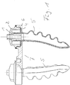
- the gripper element formed with a plurality of bending elements 5 opens and can be placed over the accessing product. Subsequently, overpressure inside the bending elements 5 ensures the actual gripping movement, in that bending elements 5 bend towards one another in an arc.
- the bending elements 5 can be used in receptacles of a base element 6 on the holder 7. An opening is formed in the base element 6 for each bending element 5. The respective bending element 5 can then be inserted with its bendable region through the opening.
- a radially circumferential flange 4 lies on a surface of the base element 6. In the example shown, in This surface area of the base element 6 has a circumferential elevation 6.1, the edges of which are rounded.
- the flange 4 has a complementary recess in this area, so that both surfaces are in direct contact with one another and form a kind of “labyrinth seal” with the elevation 6.1 and the recess 4.1. In this example, the flange 4 is rotationally symmetrical in the form of a circular ring.
- An internal thread 6.3 is formed on the base element 6 around the opening and the bending element 5, with which a fastening element 2, which has a corresponding external thread, can be fastened to the base element 6.
- the fastening element 2 is designed in the form of a union nut with a bore. A part of a connecting piece 1 is led through the bore to the outside. A fluid, in particular compressed air, can be fed into the cavity of the bending element 5 via the connecting piece 1. With increased internal pressure, this bends in Figure 2 shown bending element 5 to the left, since its right side has greater extensibility.
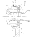
- the connecting piece 1 is inserted into a hollow cylindrical region of the bending element 5 and, in this example, has a profiling on its outer wall there, with which there is also a positive connection for the non-positive connection, due to the elasticity of the bending element material and the dimensioning of the outer diameter of the connecting piece 1 and the inner diameter of the hollow cylindrical region of the bending element 5 in the connection region of the two elements is reached bar.
- a stop 6.2 is formed on the base element 6, which forms a path limitation for the fastening element 2.
- a circumferential seal 8 is also present in this area. The fastener 2 can therefore only are screwed in until a predetermined maximum pressure force acts between the end face of the fastening element 2, the flange 4 and the bearing surface of the flange 4 on the base element 6.
- the fastening element 2 and the connecting piece 1 can be a part. But there is also the possibility to use two separate parts for it. Then a bore is formed in the central longitudinal axis of the fastening element 2, through which a part of the connecting piece 1 is guided outwards in the direction of a pressure container (not shown) of a control or regulatable pneumatic or hydraulic system.
- the connection piece 1 lies with a collar-shaped area on an inner wall of the fastening element 2, which forms an abutment for this collar-shaped area of the connection piece 1.
- the connecting piece 1 is moved with the screwing movement of the fastening element 2 and the hollow cylindrical region of the bending element 5, so that the flange 4 with the end face of the fastening element 2 is pressed against the surface of the base element 6 provided with the elevation 6.1 and thus fixed.
- the hollow cylindrical region of the bending element 5 is plugged on the outside of the region of the connecting piece 1 arranged within the fastening element 2.
- the end face of the fastening element 2 which is brought into contact with the flange 4, is inclined.
- An angle of 5 ° was chosen.
- the inward-facing edge of the end face of the fastening element 2 projects deeper into the flange material than the radially outward-pointing edge. In this way, an additional positive connection and thereby a further improved sealing between the inner and outer areas can be achieved.
Landscapes
- Engineering & Computer Science (AREA)
- Robotics (AREA)
- Mechanical Engineering (AREA)
- Life Sciences & Earth Sciences (AREA)
- Food Science & Technology (AREA)
- Clamps And Clips (AREA)
Priority Applications (1)
| Application Number | Priority Date | Filing Date | Title |
|---|---|---|---|
| PL16160656T PL3069830T3 (pl) | 2015-03-19 | 2016-03-16 | Element chwytakowy z elastycznie odkształcalnym w kierunku uprzywilejowanym elementem zginanym oraz uchwytem |
Applications Claiming Priority (1)
| Application Number | Priority Date | Filing Date | Title |
|---|---|---|---|
| DE102015204986.8A DE102015204986B3 (de) | 2015-03-19 | 2015-03-19 | Greiferelement mit einem elastisch in einer Vorzugsrichtung verformbaren Biegeelement und Halterung |
Publications (3)
| Publication Number | Publication Date |
|---|---|
| EP3069830A2 EP3069830A2 (de) | 2016-09-21 |
| EP3069830A3 EP3069830A3 (de) | 2016-12-14 |
| EP3069830B1 true EP3069830B1 (de) | 2020-02-26 |
Family
ID=55661184
Family Applications (1)
| Application Number | Title | Priority Date | Filing Date |
|---|---|---|---|
| EP16160656.1A Active EP3069830B1 (de) | 2015-03-19 | 2016-03-16 | Greiferelement mit einem elastisch in einer vorzugsrichtung verformbaren biegeelement und halterung |
Country Status (5)
| Country | Link |
|---|---|
| EP (1) | EP3069830B1 (pl) |
| DE (1) | DE102015204986B3 (pl) |
| DK (1) | DK3069830T3 (pl) |
| ES (1) | ES2781081T3 (pl) |
| PL (1) | PL3069830T3 (pl) |
Families Citing this family (13)
| Publication number | Priority date | Publication date | Assignee | Title |
|---|---|---|---|---|
| DE102016125271B4 (de) * | 2016-12-21 | 2023-11-30 | Wegard Gmbh | Modulares Aktorsystem, Fluidaktor und Kupplungsvorrichtung für ein modulares Aktorsystem |
| EP3530415B1 (en) * | 2018-02-27 | 2024-07-24 | Piab Ab | Vacuum powered gripper |
| CN108748250B (zh) * | 2018-06-19 | 2021-11-16 | 河海大学常州校区 | 一种嵌入橡胶软管的软体机械手 |
| CN108818591A (zh) * | 2018-07-25 | 2018-11-16 | 清华大学 | 柔性抓持装置 |
| CN109760099B (zh) * | 2019-01-22 | 2023-10-03 | 广东工业大学 | 一种软硬混合约束纯二维双向张合的气动软体夹持器 |
| DE202019102610U1 (de) | 2019-05-09 | 2019-08-27 | Hohe Tanne Gmbh | Greifervorrichtung |
| DE102019112125B4 (de) * | 2019-05-09 | 2024-10-31 | Hohe Tanne Gmbh | Greifervorrichtung mit einer mittels Überdruck und Unterdruck pneumatisch betätigbaren Greifereinheit |
| CN110253602B (zh) * | 2019-07-12 | 2024-11-08 | 北京软体机器人科技股份有限公司 | 一种内撑式夹具 |
| CN111347450A (zh) * | 2020-04-29 | 2020-06-30 | 江苏汉格智能科技有限公司 | 一种用于圆件的两爪气缸夹爪机构 |
| CN113319886A (zh) * | 2021-07-16 | 2021-08-31 | 北京软体机器人科技有限公司 | 柔性夹具 |
| JP2023173342A (ja) * | 2022-05-25 | 2023-12-07 | 公立大学法人公立はこだて未来大学 | シート、駆動部品、駆動部品の組み立て方法および駆動部品の駆動方法 |
| CN117549341B (zh) * | 2023-12-26 | 2026-01-13 | 深圳柔触机器人科技有限公司 | 一种负压内撑柔性爪 |
| DE102024106317B3 (de) * | 2024-03-05 | 2025-06-12 | Festo Se & Co. Kg | Greiffinger mit einstückig aneinandergereihten und getrennt druckbeaufschlagbaren Fingersegmenten zum Ergreifen von Gegenständen |
Family Cites Families (4)
| Publication number | Priority date | Publication date | Assignee | Title |
|---|---|---|---|---|
| US3343864A (en) * | 1965-10-07 | 1967-09-26 | James I Baer | Material handling apparatus and the like |
| US5251538A (en) * | 1991-08-21 | 1993-10-12 | Battelle Memorial Institute | Prehensile apparatus |
| JPH09103983A (ja) * | 1995-10-06 | 1997-04-22 | Kubota Corp | ロボットハンド用指 |
| DE112011101331T5 (de) * | 2010-04-15 | 2013-01-31 | Cornell University | Greif- und Ablegevorrichtung und -verfahren |
-
2015
- 2015-03-19 DE DE102015204986.8A patent/DE102015204986B3/de not_active Expired - Fee Related
-
2016
- 2016-03-16 DK DK16160656.1T patent/DK3069830T3/da active
- 2016-03-16 ES ES16160656T patent/ES2781081T3/es active Active
- 2016-03-16 PL PL16160656T patent/PL3069830T3/pl unknown
- 2016-03-16 EP EP16160656.1A patent/EP3069830B1/de active Active
Non-Patent Citations (1)
| Title |
|---|
| None * |
Also Published As
| Publication number | Publication date |
|---|---|
| DK3069830T3 (da) | 2020-03-30 |
| DE102015204986B3 (de) | 2016-08-04 |
| EP3069830A2 (de) | 2016-09-21 |
| EP3069830A3 (de) | 2016-12-14 |
| PL3069830T3 (pl) | 2020-09-21 |
| ES2781081T3 (es) | 2020-08-28 |
Similar Documents
| Publication | Publication Date | Title |
|---|---|---|
| EP3069830B1 (de) | Greiferelement mit einem elastisch in einer vorzugsrichtung verformbaren biegeelement und halterung | |
| DE102010064071B3 (de) | Klemmring, Kabelverschraubung und Verfahren zum Montieren einer Kabelverschraubung | |
| EP2369211B1 (de) | Vorrichtung für eine abgedichtete Durchführung von Langformteilen | |
| EP1319451A1 (de) | Stutzen für ein Wandteil, insbesondere für ein Wandteil eines Deckels oder Behälters | |
| WO2001040693A2 (de) | Rohrverbindung und verfahren zu ihrer herstellung | |
| DE3025279A1 (de) | Korrosionsbestaendige rohrverbindung | |
| DE202014100438U1 (de) | Verpackung für eine Pedikelschraube | |
| EP3173675A1 (de) | Schlauchanschluss | |
| EP3382239A1 (de) | Verschliessbare behälter-anordnung | |
| DE102017216861A1 (de) | Pneumatischer Einzelfinger-Winkelgreifer und Verfahren zur Herstellung desselben | |
| WO2018099666A1 (de) | Druckaufnehmer mit einem prozessanschluss | |
| EP3452746A1 (de) | Verbindungsvorrichtung, insbesondere in form einer schlauchkupplung | |
| EP3070389B1 (de) | Schlauchverschraubung | |
| EP2918354B1 (de) | Pressaufsatz zum axialen Verpressen von Werkstücken | |
| EP3180543B1 (de) | Schwingungselement mit entkoppeltem bauteil | |
| DE60307895T2 (de) | Anordnung und verfahren zur durchführung des ergreifens und abdichtens der mündung hohler objekte von innerhalb der mündung heraus in verbindung mit der dichtungsprüfung des objekts | |
| EP2995825B1 (de) | Pendelauflage | |
| DE102016014828B4 (de) | Packtulpe zum kopfseitigen Ergreifen von Flaschen | |
| DE102004020478B3 (de) | Rohrverbindung mit definierter Dichtwirkung | |
| EP3158209B1 (de) | Verfahren zum verpressen einer kugel mit einem ersten bauteil | |
| DE828176C (de) | Endarmatur fuer nahtlose Rohre | |
| DE102012210837A1 (de) | Trokarvorrichtung | |
| DE102011109451A1 (de) | Vorrichtung zur Halterung eines Gewindestifts | |
| DE102015226536A1 (de) | Kabelverschraubung | |
| DE102014007410A1 (de) | Probenbehälter mit Versiegelungsfunktion |
Legal Events
| Date | Code | Title | Description |
|---|---|---|---|
| PUAI | Public reference made under article 153(3) epc to a published international application that has entered the european phase |
Free format text: ORIGINAL CODE: 0009012 |
|
| AK | Designated contracting states |
Kind code of ref document: A2 Designated state(s): AL AT BE BG CH CY CZ DE DK EE ES FI FR GB GR HR HU IE IS IT LI LT LU LV MC MK MT NL NO PL PT RO RS SE SI SK SM TR |
|
| AX | Request for extension of the european patent |
Extension state: BA ME |
|
| PUAL | Search report despatched |
Free format text: ORIGINAL CODE: 0009013 |
|
| AK | Designated contracting states |
Kind code of ref document: A3 Designated state(s): AL AT BE BG CH CY CZ DE DK EE ES FI FR GB GR HR HU IE IS IT LI LT LU LV MC MK MT NL NO PL PT RO RS SE SI SK SM TR |
|
| AX | Request for extension of the european patent |
Extension state: BA ME |
|
| RIC1 | Information provided on ipc code assigned before grant |
Ipc: B25J 15/12 20060101ALI20161108BHEP Ipc: B25J 15/00 20060101AFI20161108BHEP |
|
| STAA | Information on the status of an ep patent application or granted ep patent |
Free format text: STATUS: REQUEST FOR EXAMINATION WAS MADE |
|
| 17P | Request for examination filed |
Effective date: 20170613 |
|
| RBV | Designated contracting states (corrected) |
Designated state(s): AL AT BE BG CH CY CZ DE DK EE ES FI FR GB GR HR HU IE IS IT LI LT LU LV MC MK MT NL NO PL PT RO RS SE SI SK SM TR |
|
| STAA | Information on the status of an ep patent application or granted ep patent |
Free format text: STATUS: EXAMINATION IS IN PROGRESS |
|
| 17Q | First examination report despatched |
Effective date: 20181107 |
|
| RIC1 | Information provided on ipc code assigned before grant |
Ipc: B25J 11/00 20060101ALI20190701BHEP Ipc: B25J 15/00 20060101AFI20190701BHEP Ipc: B25J 15/12 20060101ALI20190701BHEP |
|
| GRAP | Despatch of communication of intention to grant a patent |
Free format text: ORIGINAL CODE: EPIDOSNIGR1 |
|
| STAA | Information on the status of an ep patent application or granted ep patent |
Free format text: STATUS: GRANT OF PATENT IS INTENDED |
|
| INTG | Intention to grant announced |
Effective date: 20190927 |
|
| GRAS | Grant fee paid |
Free format text: ORIGINAL CODE: EPIDOSNIGR3 |
|
| GRAA | (expected) grant |
Free format text: ORIGINAL CODE: 0009210 |
|
| STAA | Information on the status of an ep patent application or granted ep patent |
Free format text: STATUS: THE PATENT HAS BEEN GRANTED |
|
| AK | Designated contracting states |
Kind code of ref document: B1 Designated state(s): AL AT BE BG CH CY CZ DE DK EE ES FI FR GB GR HR HU IE IS IT LI LT LU LV MC MK MT NL NO PL PT RO RS SE SI SK SM TR |
|
| REG | Reference to a national code |
Ref country code: GB Ref legal event code: FG4D Free format text: NOT ENGLISH |
|
| REG | Reference to a national code |
Ref country code: CH Ref legal event code: EP |
|
| REG | Reference to a national code |
Ref country code: AT Ref legal event code: REF Ref document number: 1237070 Country of ref document: AT Kind code of ref document: T Effective date: 20200315 |
|
| REG | Reference to a national code |
Ref country code: IE Ref legal event code: FG4D Free format text: LANGUAGE OF EP DOCUMENT: GERMAN |
|
| REG | Reference to a national code |
Ref country code: DE Ref legal event code: R096 Ref document number: 502016008876 Country of ref document: DE |
|
| REG | Reference to a national code |
Ref country code: DK Ref legal event code: T3 Effective date: 20200327 |
|
| REG | Reference to a national code |
Ref country code: CH Ref legal event code: NV Representative=s name: VALIPAT S.A. C/O BOVARD SA NEUCHATEL, CH Ref country code: NL Ref legal event code: FP |
|
| REG | Reference to a national code |
Ref country code: SE Ref legal event code: TRGR |
|
| PG25 | Lapsed in a contracting state [announced via postgrant information from national office to epo] |
Ref country code: RS Free format text: LAPSE BECAUSE OF FAILURE TO SUBMIT A TRANSLATION OF THE DESCRIPTION OR TO PAY THE FEE WITHIN THE PRESCRIBED TIME-LIMIT Effective date: 20200226 Ref country code: FI Free format text: LAPSE BECAUSE OF FAILURE TO SUBMIT A TRANSLATION OF THE DESCRIPTION OR TO PAY THE FEE WITHIN THE PRESCRIBED TIME-LIMIT Effective date: 20200226 Ref country code: NO Free format text: LAPSE BECAUSE OF FAILURE TO SUBMIT A TRANSLATION OF THE DESCRIPTION OR TO PAY THE FEE WITHIN THE PRESCRIBED TIME-LIMIT Effective date: 20200526 |
|
| REG | Reference to a national code |
Ref country code: LT Ref legal event code: MG4D |
|
| REG | Reference to a national code |
Ref country code: ES Ref legal event code: FG2A Ref document number: 2781081 Country of ref document: ES Kind code of ref document: T3 Effective date: 20200828 |
|
| PG25 | Lapsed in a contracting state [announced via postgrant information from national office to epo] |
Ref country code: IS Free format text: LAPSE BECAUSE OF FAILURE TO SUBMIT A TRANSLATION OF THE DESCRIPTION OR TO PAY THE FEE WITHIN THE PRESCRIBED TIME-LIMIT Effective date: 20200626 Ref country code: BG Free format text: LAPSE BECAUSE OF FAILURE TO SUBMIT A TRANSLATION OF THE DESCRIPTION OR TO PAY THE FEE WITHIN THE PRESCRIBED TIME-LIMIT Effective date: 20200526 Ref country code: HR Free format text: LAPSE BECAUSE OF FAILURE TO SUBMIT A TRANSLATION OF THE DESCRIPTION OR TO PAY THE FEE WITHIN THE PRESCRIBED TIME-LIMIT Effective date: 20200226 Ref country code: LV Free format text: LAPSE BECAUSE OF FAILURE TO SUBMIT A TRANSLATION OF THE DESCRIPTION OR TO PAY THE FEE WITHIN THE PRESCRIBED TIME-LIMIT Effective date: 20200226 Ref country code: GR Free format text: LAPSE BECAUSE OF FAILURE TO SUBMIT A TRANSLATION OF THE DESCRIPTION OR TO PAY THE FEE WITHIN THE PRESCRIBED TIME-LIMIT Effective date: 20200527 |
|
| PG25 | Lapsed in a contracting state [announced via postgrant information from national office to epo] |
Ref country code: PT Free format text: LAPSE BECAUSE OF FAILURE TO SUBMIT A TRANSLATION OF THE DESCRIPTION OR TO PAY THE FEE WITHIN THE PRESCRIBED TIME-LIMIT Effective date: 20200719 Ref country code: SM Free format text: LAPSE BECAUSE OF FAILURE TO SUBMIT A TRANSLATION OF THE DESCRIPTION OR TO PAY THE FEE WITHIN THE PRESCRIBED TIME-LIMIT Effective date: 20200226 Ref country code: EE Free format text: LAPSE BECAUSE OF FAILURE TO SUBMIT A TRANSLATION OF THE DESCRIPTION OR TO PAY THE FEE WITHIN THE PRESCRIBED TIME-LIMIT Effective date: 20200226 Ref country code: SK Free format text: LAPSE BECAUSE OF FAILURE TO SUBMIT A TRANSLATION OF THE DESCRIPTION OR TO PAY THE FEE WITHIN THE PRESCRIBED TIME-LIMIT Effective date: 20200226 Ref country code: RO Free format text: LAPSE BECAUSE OF FAILURE TO SUBMIT A TRANSLATION OF THE DESCRIPTION OR TO PAY THE FEE WITHIN THE PRESCRIBED TIME-LIMIT Effective date: 20200226 Ref country code: LT Free format text: LAPSE BECAUSE OF FAILURE TO SUBMIT A TRANSLATION OF THE DESCRIPTION OR TO PAY THE FEE WITHIN THE PRESCRIBED TIME-LIMIT Effective date: 20200226 |
|
| REG | Reference to a national code |
Ref country code: DE Ref legal event code: R097 Ref document number: 502016008876 Country of ref document: DE |
|
| PG25 | Lapsed in a contracting state [announced via postgrant information from national office to epo] |
Ref country code: MC Free format text: LAPSE BECAUSE OF FAILURE TO SUBMIT A TRANSLATION OF THE DESCRIPTION OR TO PAY THE FEE WITHIN THE PRESCRIBED TIME-LIMIT Effective date: 20200226 |
|
| PG25 | Lapsed in a contracting state [announced via postgrant information from national office to epo] |
Ref country code: LU Free format text: LAPSE BECAUSE OF NON-PAYMENT OF DUE FEES Effective date: 20200316 |
|
| PLBE | No opposition filed within time limit |
Free format text: ORIGINAL CODE: 0009261 |
|
| STAA | Information on the status of an ep patent application or granted ep patent |
Free format text: STATUS: NO OPPOSITION FILED WITHIN TIME LIMIT |
|
| PG25 | Lapsed in a contracting state [announced via postgrant information from national office to epo] |
Ref country code: IE Free format text: LAPSE BECAUSE OF NON-PAYMENT OF DUE FEES Effective date: 20200316 |
|
| 26N | No opposition filed |
Effective date: 20201127 |
|
| PG25 | Lapsed in a contracting state [announced via postgrant information from national office to epo] |
Ref country code: SI Free format text: LAPSE BECAUSE OF FAILURE TO SUBMIT A TRANSLATION OF THE DESCRIPTION OR TO PAY THE FEE WITHIN THE PRESCRIBED TIME-LIMIT Effective date: 20200226 |
|
| PG25 | Lapsed in a contracting state [announced via postgrant information from national office to epo] |
Ref country code: TR Free format text: LAPSE BECAUSE OF FAILURE TO SUBMIT A TRANSLATION OF THE DESCRIPTION OR TO PAY THE FEE WITHIN THE PRESCRIBED TIME-LIMIT Effective date: 20200226 Ref country code: MT Free format text: LAPSE BECAUSE OF FAILURE TO SUBMIT A TRANSLATION OF THE DESCRIPTION OR TO PAY THE FEE WITHIN THE PRESCRIBED TIME-LIMIT Effective date: 20200226 Ref country code: CY Free format text: LAPSE BECAUSE OF FAILURE TO SUBMIT A TRANSLATION OF THE DESCRIPTION OR TO PAY THE FEE WITHIN THE PRESCRIBED TIME-LIMIT Effective date: 20200226 |
|
| PG25 | Lapsed in a contracting state [announced via postgrant information from national office to epo] |
Ref country code: MK Free format text: LAPSE BECAUSE OF FAILURE TO SUBMIT A TRANSLATION OF THE DESCRIPTION OR TO PAY THE FEE WITHIN THE PRESCRIBED TIME-LIMIT Effective date: 20200226 Ref country code: AL Free format text: LAPSE BECAUSE OF FAILURE TO SUBMIT A TRANSLATION OF THE DESCRIPTION OR TO PAY THE FEE WITHIN THE PRESCRIBED TIME-LIMIT Effective date: 20200226 |
|
| P01 | Opt-out of the competence of the unified patent court (upc) registered |
Effective date: 20230524 |
|
| PGFP | Annual fee paid to national office [announced via postgrant information from national office to epo] |
Ref country code: SE Payment date: 20250311 Year of fee payment: 10 |
|
| PGFP | Annual fee paid to national office [announced via postgrant information from national office to epo] |
Ref country code: DE Payment date: 20250319 Year of fee payment: 10 |
|
| PGFP | Annual fee paid to national office [announced via postgrant information from national office to epo] |
Ref country code: DK Payment date: 20250321 Year of fee payment: 10 Ref country code: NL Payment date: 20250324 Year of fee payment: 10 |
|
| PGFP | Annual fee paid to national office [announced via postgrant information from national office to epo] |
Ref country code: BE Payment date: 20250320 Year of fee payment: 10 Ref country code: AT Payment date: 20250319 Year of fee payment: 10 |
|
| PGFP | Annual fee paid to national office [announced via postgrant information from national office to epo] |
Ref country code: PL Payment date: 20250303 Year of fee payment: 10 Ref country code: FR Payment date: 20250324 Year of fee payment: 10 Ref country code: CZ Payment date: 20250228 Year of fee payment: 10 |
|
| PGFP | Annual fee paid to national office [announced via postgrant information from national office to epo] |
Ref country code: GB Payment date: 20250324 Year of fee payment: 10 |
|
| PGFP | Annual fee paid to national office [announced via postgrant information from national office to epo] |
Ref country code: ES Payment date: 20250416 Year of fee payment: 10 |
|
| PGFP | Annual fee paid to national office [announced via postgrant information from national office to epo] |
Ref country code: IT Payment date: 20250331 Year of fee payment: 10 |
|
| PGFP | Annual fee paid to national office [announced via postgrant information from national office to epo] |
Ref country code: CH Payment date: 20250401 Year of fee payment: 10 |