EP3069526B1 - Kommunikationsmodul - Google Patents
Kommunikationsmodul Download PDFInfo
- Publication number
- EP3069526B1 EP3069526B1 EP14796133.8A EP14796133A EP3069526B1 EP 3069526 B1 EP3069526 B1 EP 3069526B1 EP 14796133 A EP14796133 A EP 14796133A EP 3069526 B1 EP3069526 B1 EP 3069526B1
- Authority
- EP
- European Patent Office
- Prior art keywords
- communication
- module
- communication module
- overvoltage protection
- protection module
- Prior art date
- Legal status (The legal status is an assumption and is not a legal conclusion. Google has not performed a legal analysis and makes no representation as to the accuracy of the status listed.)
- Active
Links
Images



Classifications
-
- H—ELECTRICITY
- H04—ELECTRIC COMMUNICATION TECHNIQUE
- H04M—TELEPHONIC COMMUNICATION
- H04M3/00—Automatic or semi-automatic exchanges
- H04M3/18—Automatic or semi-automatic exchanges with means for reducing interference or noise; with means for reducing effects due to line faults with means for protecting lines
-
- H—ELECTRICITY
- H04—ELECTRIC COMMUNICATION TECHNIQUE
- H04Q—SELECTING
- H04Q1/00—Details of selecting apparatus or arrangements
- H04Q1/02—Constructional details
- H04Q1/14—Distribution frames
- H04Q1/146—Distribution frames with line protection means
-
- H—ELECTRICITY
- H02—GENERATION; CONVERSION OR DISTRIBUTION OF ELECTRIC POWER
- H02H—EMERGENCY PROTECTIVE CIRCUIT ARRANGEMENTS
- H02H9/00—Emergency protective circuit arrangements for limiting excess current or voltage without disconnection
- H02H9/04—Emergency protective circuit arrangements for limiting excess current or voltage without disconnection responsive to excess voltage
- H02H9/042—Emergency protective circuit arrangements for limiting excess current or voltage without disconnection responsive to excess voltage comprising means to limit the absorbed power or indicate damaged over-voltage protection device
-
- H—ELECTRICITY
- H04—ELECTRIC COMMUNICATION TECHNIQUE
- H04L—TRANSMISSION OF DIGITAL INFORMATION, e.g. TELEGRAPHIC COMMUNICATION
- H04L43/00—Arrangements for monitoring or testing data switching networks
- H04L43/06—Generation of reports
- H04L43/065—Generation of reports related to network devices
-
- H—ELECTRICITY
- H04—ELECTRIC COMMUNICATION TECHNIQUE
- H04M—TELEPHONIC COMMUNICATION
- H04M1/00—Substation equipment, e.g. for use by subscribers
- H04M1/738—Interface circuits for coupling substations to external telephone lines
- H04M1/74—Interface circuits for coupling substations to external telephone lines with means for reducing interference; with means for reducing effects due to line faults
- H04M1/745—Protection devices or circuits for voltages surges on the line
Definitions
- the present invention relates to a communication module with a communication circuit with a communication interface for transmitting data on an electrical data line.
- overvoltage protection is therefore fundamental in many industrial, wired long-distance communication applications. Separate overvoltage protection can be used for communication modules. This surge protection does not include a communication interface to the communication module.
- the publication DE 200 01 752 U1 discloses a surge protection magazine and a distribution device for telecommunications technology.
- the surge protection magazine can be plugged onto a support element and is connected to a connection strip and, if necessary, to a cable connector to form a connection system.
- connection module with a receiving slot for receiving a current and voltage limiting circuit protection module is disclosed.
- the publication DE 100 00 098 A1 relates to a satellite-based communication system with return channel routing via the D channel of an ISDN connection.
- the object is achieved by a communication module, with a communication circuit with a communication interface for transmitting data on an electrical data line and an overvoltage protection module for protecting the communication circuit from an overvoltage on the electrical data line, which is pluggable and integrated into the communication module.
- a communication module with a communication circuit with a communication interface for transmitting data on an electrical data line and an overvoltage protection module for protecting the communication circuit from an overvoltage on the electrical data line, which is pluggable and integrated into the communication module.
- the pluggable overvoltage protection module comprises a gas arrester, a protective diode and/or a thyristor. This achieves, for example, the technical advantage that an overvoltage can be efficiently dissipated.
- the pluggable overvoltage protection module has a single connection side for electrically connecting the overvoltage protection module to the communication circuit. This achieves, for example, the technical advantage that the overvoltage protection module can be easily inserted into the communication module.
- the pluggable overvoltage protection module can be plugged into the communication module in a secure connection. This achieves, for example, the technical advantage that incorrect connection of the surge protection module can be prevented.
- the overvoltage protection module is integrated in a protection module housing and the communication circuit is integrated in a circuit housing. This achieves the technical advantage, for example, that damage to the modules can be prevented.
- the protective module housing and the circuit housing are adapted to one another in terms of shape in order to prevent incorrect insertion of the overvoltage protection module. This achieves, for example, the technical advantage of preventing incorrect insertion of the surge protection module.
- the communication module can be mounted on a top-hat rail. This achieves, for example, the technical advantage that the communication module can be installed quickly. With appropriate design, the overvoltage can be dissipated via the mechanical fastening of the communication module on the top-hat rail. This further reduces the wiring effort and eliminates the need to connect a protective conductor.
- the communication circuit comprises a plurality of communication interfaces for transmitting data on one electrical data line
- the pluggable overvoltage protection module is designed to protect against overvoltage on each of the electrical data lines.
- the overvoltage protection module is designed to detect an overvoltage on the electrical data line. This achieves, for example, the technical advantage that a digital fault message can be generated in response to the detected fault.
- the communication module comprises a data interface for transmitting data between the overvoltage protection module and the communication circuit.
- the overvoltage protection module is designed to send a state of the overvoltage protection module to the communication circuit. This also achieves the technical advantage, for example, that the processing capacity of the communication module can be used to forward or process the fault report.
- the communication circuit comprises a remote communication interface for sending the state of the overvoltage protection module to an external data network.
- the external data network is a local network or a mobile radio network. This achieves, for example, the technical advantage that the data can be transferred to mobile devices.
- the communication module comprises a web server for externally querying the status of the surge protection module. This achieves, for example, the technical advantage that the status can be queried with little effort.
- the communication module is a modem, a switch or a router.
- the surge protection module can, for example, protect Ethernet data lines or be used for the supply voltage of a device.
- Fig. 1 shows a schematic view of a surge protector 205.
- the surge protector 205 has two connections that form an input IN and an output OUT of the surge protector 205.
- the input IN and output OUT can be swapped. If the surge protection 205 is connected incorrectly, for example if the connections are swapped, the function of the surge protection can no longer be guaranteed.
- Fig. 2 shows a schematic view of a communication module 200 with external surge protection 205.
- the surge protection 205 is an additional component in a control cabinet and takes up additional space.
- the surge protector 205 is wired to the communication module 200 using electrical cables. This results in increased wiring effort.
- the communication module 200 such as an SHDSL Ethernet extender
- the surge protector 205 has more than one input and one output
- the lines between the communication module 200 and the surge protector 205 may be incorrectly wired.
- the inputs IN1 and IN2 and the outputs OUT1 and OUT2 are wired correctly, the DSL port DSL1 and DSL port DSL2 are cross-wired. This creates a wiring error between the communication module 200 and the surge protector 205.
- a special surge protector 205 is used, which provides a large transmission bandwidth and allows high frequency to pass through. In this case, if a standard surge protector is used, high-speed communication cannot be performed. The correct selection of the surge protector 205 is therefore a prerequisite for successful broadband communication. When communicating between two participants (transmitter-receiver), incorrect wiring of the surge protector 205 can occur on both sides. This also increases the probability that an error will occur in more than one station.
- Fig. 3 shows a schematic view of a communication module 100 with integrated overvoltage protection module 105 in point-to-point communication.
- the communication module 100 includes a communication circuit 101 with a communication interface for transmitting data on an electrical data line 103.
- the communication circuit 101 forms, for example, a modem/router assembly.
- the data line 103 consists, for example, of a pair of electrical conductors for long-distance communication.
- the communication module 100 is connected to another communication module via networks 111 and a remote communication interface 109.
- the other communication module can be, for example, a mobile radio modem that transmits a local alarm from the surge protection module 105 to other networks or via which the communication module 100 can be accessed.
- the surge protection module 105 is integrated into the communication module 100 as a pluggable module.
- the overvoltage protection module 105 includes, for example, a gas arrester or a protective diode, both components in combination, or further protective elements.
- both Gas arresters can be used as coarse protection and protective diodes/thyristors can be used as fine protection.
- the surge protection module 105 provides a pluggable surge protection with only one connection side for the user.
- a pluggable surge protection module 105 simple communication between the surge protection module 105 and the communication module 100 via a data interface 107 can be realized.
- the communication module 100 can be used in point-to-point communication.
- a data interface 107 for communication is formed between the communication module 100 and the overvoltage protection module 105.
- the overvoltage protection module 105 detects a fault on the electrical data line 103. In a simple case, a “gas arrester ignited” status can be recognized. Surge protection module 105 then passes on the detected status to the communication circuit 101, such as a network/modem/router assembly. The communication circuit 101 can then react and further process or forward the status.
- the communication module 100 can automatically send an alarm via the local network 111 indicating that the surge protection module 100 is previously damaged. This means that a user can be informed promptly before a device failure. The user can integrate a new surge protection module 105 into the communication link in a timely manner, reducing the probability of failure and increasing availability.
- diagnostic data can be output as simple plain text, for example with the character string “Surge protection previously damaged”.
- the diagnostic data can be presented as a graphical representation via web-based management, such as a timeline, bar chart, statistics or probability.
- the communication modules 100 can also distribute the diagnostic data of their own surge protection module 105 to other participants, for example via a LAN - Local Area Network or worldwide via a WAN - Wide Area Network. This makes it possible to easily implement a central or decentralized information database.
- Fig. 4 shows a schematic view of a communication module 100 with multiple communication interfaces in line/ring/mixed structure communication.
- a user may actively query the status of the surge protection module 105 remotely via the local network 111, such as via SNMP or via access to a web page.
- the communication module 100 has more than one remote communication interface 109.
- the communication modules 100 can thereby be connected in a line, in a ring, or in a mixed structure.
- the status of each surge protection module 105 can thus also be transmitted to other remote devices, which in turn forward the status or an alarm, for example to other remote devices or in the corresponding local network.
- Fig. 5 shows a schematic view of a communication module 100 with several communication interfaces and a status query in a mixed structure in which remote communication takes place via different media.
- the status transmission/status query of the surge protection module 105 takes place via different media, such as wired and/or wireless via mobile radio 113.
- the communication module 100 can have any design.
- the communication module 100 can be mounted with a housing on a top-hat rail or implemented in the form of a 19" slot, such as for a control center.
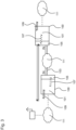
- Fig. 6 shows a typical application of a DSL router as a communication module 100 in the public telephone network.
- the DSL router 300 of a subscriber 301 communicates with a Digital Subscriber Line Access Multiplexer (DSLAM) 321 in an exchange 303.
- DSLAM Digital Subscriber Line Access Multiplexer
- the subscriber 301 is connected to the exchange 303 via the splitters 311 and 313 and the subscriber line 315 as a data line.
- the subscriber 301 includes a telephone 305, a network termination device (NTBA) 307, a personal computer 309 and the DSL router 300 as a communication module 100.
- the DSL router 300 includes the surge protection module.
- the exchange 303 includes a digital exchange 317, a broadband access server (DSL-AC) 319 and the Digital Subscriber Line Access Multiplexer (DSL-AM) 321.
- the exchange 303 is connected to the telephone network 323 and the Internet 325.
Landscapes
- Engineering & Computer Science (AREA)
- Signal Processing (AREA)
- Computer Networks & Wireless Communication (AREA)
- Emergency Protection Circuit Devices (AREA)
Description
- Die vorliegende Erfindung betrifft ein Kommunikationsmodul mit einer Kommunikationsschaltung mit einer Kommunikationsschnittstelle zum Übermitteln von Daten auf einer elektrischen Datenleitung.
- Im letzten Jahrhundert war eine Schmalband-Kommunikation in vielen Industrieanwendungen ausreichend. Über große Entfernungen wurden Kupferleitungen verlegt, da diese die gewünschten Anforderungen optimal erfüllten. Heutzutage kommunizieren immer mehr Steuerungen, Industrie-PCs und vergleichbare Komponenten jedoch über Ethernet untereinander oder mit einer Leitzentrale. Die zu übertragende Datenmenge hat sich somit vervielfacht. Der Bedarf an einer Breitbandkommunikation wächst kontinuierlich. Neue Kommunikationsstrecken werden daher nicht mehr mit Kupfersondern häufig mit Glasfaserkabel aufgebaut. Ein Austausch alter, bereits verlegter Kupferleitungen durch moderne Glasfaserkabel ist oftmals teuer und zeitaufwändig. Daher wird eine moderne Hochgeschwindigkeits-Kommunikation in vielen Fällen über die alten, bestehenden Kupferleitungen realisiert.
- Auch wenn heutzutage über alte Kupferleitungen große Datenraten schnell übertragen werden können, wie beispielsweise über moderne Modulationsverfahren wie DSL, besteht das Problem, dass die Kupferadern auch elektromagnetische Störungen übertragen, die wiederum das Kommunikationsmodul beschädigen können, wie beispielsweise Überspannungen durch einen entfernten Blitzeinschlag. Die Verwendung eines geeigneten Überspannungsschutzes ist somit elementar in vielen industriellen, drahtgebundenen Fernkommunikationsanwendungen. Für Kommunikationsmodule kann ein separater Überspannungsschutz verwendet werden. Dieser Überspannungsschutz umfasst keine Kommunikationsschnittstelle zum Kommunikationsmodul.
- Die Druckschrift
DE 200 01 752 U1 offenbart ein Überspannungsschutzmagazin und eine Verteilereinrichtung der Telekommunikationstechnik. Das Überspannungsschutzmagazin ist auf ein Trägerelement aufsteckbar und ist mit einer Anschlussleiste und gegebenenfalls mit einem Kabelstecker zur Ausbildung eines Anschlusssystems verbunden. - In der
US 5,805,404 A ist ein Verbindungsmodul mit einem Aufnahmeschlitz zur Aufnahme eines strom- und spannungsbegrenzenden Schaltungsschutzmoduls offenbart. - Die Druckschrift
US 2002/141543 A1 offenbart ein graphisches Userinterface zum Testen von Telefonleitungen. - Die Druckschrift
DE 100 00 098 A1 betrifft ein satellitengestütztes Kommunikationssystem mit Rückkanalführung über den D-Kanal eines ISDN-Anschlusses. - Die Druckschrift
US 2007/003056 A1 offenbart in der Zusammenfassung eine Anordnung mit einem Telekommunikationsmodul und einem Schutzstecker. - Es ist die der Erfindung zugrundeliegende Aufgabe, ein Kommunikationsmodul mit einem Überspannungsschutz anzugeben, bei dem ein Verdrahtungsaufwand verringert wird und eine Fehlverdrahtung eines Überspannungsschutzes verhindert wird.
- Diese Aufgabe wird durch den Gegenstand mit den Merkmalen nach dem unabhängigen Anspruch gelöst. Vorteilhafte Ausführungsformen der Erfindung sind Gegenstand der Figuren, der Beschreibung und der abhängigen Ansprüche.
- Gemäß einem Aspekt der Erfindung wird die Aufgabe durch ein Kommunikationsmodul gelöst, mit einer Kommunikationsschaltung mit einer Kommunikationsschnittstelle zum Übermitteln von Daten auf einer elektrischen Datenleitung und einem Überspannungsschutzmodul zum Schützen der Kommunikationsschaltung vor einer Überspannung auf der elektrischen Datenleitung, das einsteckbar in das Kommunikationsmodul integriert ist. Dadurch wird beispielsweise der technische Vorteil erreicht, dass das Überspannungsschutzmodul bei einem Defekt ausgetauscht werden kann und sich ein Verdrahtungsaufwand verringert.
- In einer vorteilhaften Ausführungsform des Kommunikationsmoduls umfasst das steckbare Überspannungsschutzmodul einen Gasableiter, eine Schutzdiode und/oder einen Thyristor. Dadurch wird beispielsweise der technische Vorteil erreicht, dass eine effiziente Ableitung einer Überspannung erfolgt.
- In einer weiteren vorteilhaften Ausführungsform des Kommunikationsmoduls weist das steckbare Überspannungsschutzmodul eine einzige Anschlussseite zum elektrischen Anschließen des Überspannungsschutzmoduls an die Kommunikationsschaltung auf. Dadurch wird beispielsweise der technische Vorteil erreicht, dass das Überspannungsschutzmodul auf einfache Weise in das Kommunikationsmodul eingesetzt werden kann.
- In einer weiteren vorteilhaften Ausführungsform des Kommunikationsmoduls ist das steckbare Überspannungsschutzmodul anschlusssicher in das Kommunikationsmodul einsteckbar. Dadurch wird beispielsweise der technische Vorteil erreicht, dass ein Fehlanschluss des Überspannungsschutzmoduls verhindert werden kann.
- In einer weiteren vorteilhaften Ausführungsform des Kommunikationsmoduls ist das Überspannungsschutzmodul in einem Schutzmodulgehäuse integriert und die Kommunikationsschaltung in einem Schaltungsgehäuse integriert. Dadurch wird beispielsweise der technische Vorteil erreicht, dass eine Beschädigung der Module verhindert werden kann.
- In einer weiteren vorteilhaften Ausführungsform des Kommunikationsmoduls sind das Schutzmodulgehäuse und das Schaltungsgehäuse formtechnisch aufeinander angepasst, um ein fehlerhaftes Einstecken des Überspannungsschutzmoduls zu verhindern. Dadurch wird beispielsweise der technische Vorteil erreicht, dass ein fehlerhaftes Einsetzen des Überspannungsschutzmoduls verhindert wird.
- In einer weiteren vorteilhaften Ausführungsform des Kommunikationsmoduls ist das Kommunikationsmodul auf einer Hutschiene montierbar. Dadurch wird beispielsweise der technische Vorteil erreicht, dass eine schnelle Montage des Kommunikationsmoduls erreicht wird. Bei entsprechender Auslegung kann die Überspannung über die mechanische Befestigung des Kommunikationsmoduls über die Hutschiene abgeleitet werden. Dadurch wird der Verdrahtungsaufwand weiter reduziert und ein Anschluss eines Schutzleiters entfällt.
- In einer weiteren vorteilhaften Ausführungsform des Kommunikationsmoduls umfasst die Kommunikationsschaltung mehrere Kommunikationsschnittstellen zum Übermitteln von Daten auf jeweils einer elektrischen Datenleitung und das steckbare Überspannungsschutzmodul ist ausgebildet, vor einer Überspannung auf jeder der elektrischen Datenleitungen zu schützen. Dadurch wird beispielsweise der technische Vorteil erreicht, dass das Kommunikationsmodul in einer Linienstruktur oder einer Ringstruktur integriert werden kann. Mehrere Kommunikationsschnittstellen können auch Baumstrukturen bilden oder zur Erhöhung eines Datendurchsatzes dienen. Beispielsweise kann das Kommunikationsmodul mit mehreren Schnittstellen ein Sternpunkt einer Sternstruktur sein, wie in einem 19-Zoll-Schrank in einer Zentrale.
- In einer weiteren vorteilhaften Ausführungsform des Kommunikationsmoduls ist das Überspannungsschutzmodul ausgebildet, eine Überspannung auf der elektrischen Datenleitung zu erfassen. Dadurch wird beispielsweise der technische Vorteil erreicht, dass eine digitale Störungsmeldung in Reaktion auf die erfasste Störung erzeugt werden kann.
- In einer weiteren vorteilhaften Ausführungsform des Kommunikationsmoduls umfasst das Kommunikationsmodul eine Datenschnittstelle zum Übermitteln von Daten zwischen dem Überspannungsschutzmodul und der Kommunikationsschaltung. Dadurch wird beispielsweise der technische Vorteil erreicht, dass die Verarbeitungskapazität des Kommunikationsmoduls zum Weiterleiten oder Verarbeitung der Störungsmeldung genutzt werden kann.
- In einer weiteren vorteilhaften Ausführungsform des Kommunikationsmoduls ist das Überspannungsschutzmodul ausgebildet, einen Zustand des Überspannungsschutzmoduls an die Kommunikationsschaltung zu senden. Dadurch wird beispielsweise ebenfalls der technische Vorteil erreicht, dass die Verarbeitungskapazität des Kommunikationsmoduls zum Weiterleiten oder Verarbeitung der Störungsmeldung genutzt werden kann.
- In einer weiteren vorteilhaften Ausführungsform des Kommunikationsmoduls umfasst die Kommunikationsschaltung eine Fernkommunikationsschnittstelle zum Senden des Zustands des Überspannungsschutzmoduls an ein externes Datennetz. Dadurch wird beispielsweise der technische Vorteil erreicht, dass ein Zustand des Überspannungsschutzmoduls von einem fern gelegenen Ort überwacht werden kann.
- In einer weiteren vorteilhaften Ausführungsform des Kommunikationsmoduls ist das externe Datennetz ein lokales Netz oder ein Mobilfunknetz. Dadurch wird beispielsweise der technische Vorteil erreicht, dass die Daten an mobile Geräte übertragen werden können.
- In einer weiteren vorteilhaften Ausführungsform des Kommunikationsmoduls umfasst das Kommunikationsmodul einen Web-Server zum externen Abfragen des Zustandes des Überspannungsschutzmoduls. Dadurch wird beispielsweise der technische Vorteil erreicht, dass der Zustand mit geringem Aufwand abgefragt werden kann.
- In einer weiteren vorteilhaften Ausführungsform des Kommunikationsmoduls ist das Kommunikationsmodul ein Modem, ein Switch oder ein Router Dadurch wird beispielsweise der technische Vorteil erreicht, dass das Kommunikationsmodul durch ein zur Datenverarbeitung geeignetes Gerät gebildet wird. Das Überspannungsschutzmodul kann beispielsweise Ethernet-Datenleitungen absichern oder für die Versorgungsspannung eines Geräts verwendet werden.
- Ausführungsbeispiele der Erfindung sind in den Zeichnungen dargestellt und werden im Folgenden näher beschrieben.
- Es zeigen:
- Fig. 1
- eine schematische Ansicht eines Überspannungsschutzes;
- Fig. 2
- eine schematische Ansicht eines Kommunikationsmoduls mit externem Überspannungsschutz;
- Fig. 3
- eine schematische Ansicht eines Kommunikationsmoduls mit integriertem Überspannungsschutzmodul in einer Punkt-zu-Punkt-Kommunikation;
- Fig. 4
- eine schematische Ansicht eines Kommunikationsmoduls mit mehreren Kommunikationsschnittstellen;
- Fig. 5
- eine schematische Ansicht eines Kommunikationsmoduls mit mehreren Kommunikationsschnittstellen und einer Statusabfrage; und
- Fig. 6
- eine typische Anwendung eines DSL-Routers als Kommunikationsmodul.
-
Fig. 1 zeigt eine schematische Ansicht eines Überspannungsschutzes 205. Der Überspannungsschutz 205 weist zwei Anschlüsse auf, die einen Eingang IN und einen Ausgang OUT des Überspannungsschutzes 205 bilden. Bei der Installation können der Eingang IN und Ausgang OUT vertauscht werden. Wird der Überspannungsschutz 205 fehlerhaft angeschlossen, wie beispielsweise bei einem Vertauschen der Anschlüsse, kann die Funktion des Überspannungsschutzes nicht mehr gewährleistet werden. -
Fig. 2 zeigt eine schematische Ansicht eines Kommunikationsmoduls 200 mit externem Überspannungsschutz 205. Der Überspannungsschutz 205 ist eine zusätzliche Komponente in einem Schaltschrank und nimmt zusätzlichen Platz ein. Der Überspannungsschutz 205 wird mittels elektrischer Leitungen mit dem Kommunikationsmodul 200 verdrahtet. Dadurch entsteht ein erhöhter Verdrahtungsaufwand. - Besitzt das Kommunikationsmodul 200, wie beispielsweise ein SHDSL-Ethernet-Extender, mehr als einen DSL-Port und hat der Überspannungsschutz 205 mehr als einen Eingang und einen Ausgang, können die Leitungen zwischen Kommunikationsmodul 200 und Überspannungsschutz 205 fehlerhaft verdrahtet werden. Obwohl die Eingänge IN1 und IN2 und die Ausgänge OUT1 und OUT2 richtig verdrahtet sind, sind der DSL-Port DSL1 und DSL-Port DSL2 überkreuz verdrahtet. Dadurch entsteht ein Verdrahtungsfehler zwischen dem Kommunikationsmodul 200 und dem Überspannungsschutz 205.
- Für eine Breitbandkommunikation wird ein spezieller Überspannungsschutz 205 verwendet, der eine große Übertragungsbandbreite bietet und eine Hochfrequenz passieren lässt. Wird in diesem Fall ein Standardüberspannungsschutz verwendet, kann keine Hochgeschwindigkeits-Kommunikation durchgeführt werden. Die richtige Auswahl des Überspannungsschutzes 205 ist somit eine Voraussetzung für eine erfolgreiche Breitbandkommunikation. Bei einer Kommunikation zwischen zwei Teilnehmern (Sender-Empfänger), kann eine Fehlverdrahtung des Überspannungsschutzes 205 auf beiden Seiten auftreten. Somit steigt auch die Wahrscheinlichkeit, dass ein Fehler in mehr als in einer Station auftritt.
- Bricht die Kommunikation zwischen zwei Kommunikationsmodulen 200 ab, kann nicht überprüft werden, ob die elektrische Datenleitung 203unterbrochen worden ist, beispielsweise durch Bagger-Arbeiten, oder ob der separate Überspannungsschutz 205 ausgelöst hat und dabei zerstört worden ist, beispielsweise durch einen Blitzschlag. Das Kommunikationsmodul 200 und der Überspannungsschutz 205, tauschen keine Informationen untereinander aus.
-
Fig. 3 zeigt eine schematische Ansicht eines Kommunikationsmoduls 100 mit integriertem Überspannungsschutzmodul 105 in einer Punkt-zu-Punkt-Kommunikation. Das Kommunikationsmodul 100 umfasst eine Kommunikationsschaltung 101 mit einer Kommunikationsschnittstelle zum Übermitteln von Daten auf einer elektrischen Datenleitung 103. Die Kommunikationsschaltung 101 bildet beispielsweise eine Modem/Router- Baugruppe. Die Datenleitung 103 besteht beispielweise aus einem Adernpaar elektrischer Leiter für die Fernkommunikation. Das Kommunikationsmodul 100 ist über Netzwerke 111 und eine Fernkommunikationsschnittstelle 109 mit einem anderen Kommunikationsmodul verbunden. Das andere Kommunikationsmodul kann beispielsweise ein Mobilfunkmodem sein, das eine lokale Alarmierung aus dem Überspannungsschutzmodul 105 in andere Netze überträgt oder über das auf das Kommunikationsmodul 100 zugegriffen werden kann. - Das Überspannungsschutzmodul 105 wird als steckbares Modul in das Kommunikationsmodul 100 integriert. Das Überspannungsschutzmodul 105 umfasst beispielsweise einen Gasableiter oder eine Schutzdiode, beide Komponenten in Kombination oder weitere Schutzelemente. Im Überspannungsschutzmodul 105 werden sowohl Gasableiter als Grobschutz als auch Schutzdioden/Thyristoren als Feinschutz verwendet werden.
- Dadurch entsteht der Vorteil, dass die Ausgänge im Kommunikationsmodul 100 und die Eingänge im Überspannungsschutzmodul 105 angeordnet sind. Dadurch können Verdrahtungsfehler vermieden werden. In das Kommunikationsmodul 100 kann ein passendes, produktspezifisches Überspannungsschutzmodul 105 eingesetzt werden.
- Durch die Integration des Überspannungsschutzmoduls 105 kann die Bauform kompakter sein. Durch das Überspannungsschutzmodul 105 wird ein steckbarer Überspannungsschutz mit nur einer Anschlussseite für den Benutzer realisiert. Zudem kann durch die Integration eines steckbaren Überspannungsschutzmoduls 105 eine einfache Kommunikation zwischen dem Überspannungsschutzmodul 105 und dem Kommunikationsmodul 100 über eine Datenschnittstelle 107 realisiert werden.
- Das Kommunikationsmodul 100 kann in einer Punkt-zu-Punkt-Kommunikation eingesetzt werden. Zwischen dem Kommunikationsmodul 100 und dem Überspannungsschutzmodul 105 ist eine Datenschnittstelle 107 zum Kommunikation gebildet. Das Überspannungsschutzmodul 105 detektiert eine Störung auf der elektrischen Datenleitung 103. In einem einfachen Fall kann ein Status "Gasableiter gezündet" erkannt werden. Überspannungsschutzmodul 105 übergibt daraufhin den erfassten Status an die Kommunikationsschaltung 101 weiter, wie beispielsweise eine Netzwerk-/Modem-/Router-Baugruppe. Die Kommunikationsschaltung 101 kann daraufhin reagieren und den Status weiterverarbeiten oder weiterleiten.
- Beispielsweise kann das Kommunikationsmodul 100 automatisch einen Alarm über das lokale Netzwerk 111 versenden, der anzeigt, dass das Überspannungsschutzmodul 100 vorgeschädigt ist. Somit kann ein Benutzer zeitnah vor einem Geräteausfall informiert werden. Der Benutzer kann rechtzeitig einen neues Überspannungsschutzmodul 105 in die Kommunikationsstrecke integrieren, die Ausfallwahrscheinlichkeiten reduzieren und die Verfügbarkeit erhöhen.
- Durch die Kombination des Kommunikationsmoduls 100 mit dem Überspannungsschutzmodul 105 können weitere Funktionen für eine Diagnose ermöglicht werden, da die Kommunikationsschaltung 101 des Kommunikationsmoduls 100 mit beispielsweise einem Linux-Betriebssystem in der Regel über mehr Rechenleistung verfügt als das steckbare Überspannungsschutzmodul mit einem Mikrokontroller. Diagnosedaten können beispielsweise als einfacher Klartext ausgegeben werden, beispielsweise mit der Zeichenkette "Überspannungsschutz vorgeschädigt".
- Die Diagnosedaten können als grafische Darstellung über das Web-Based-Management dargestellt werden, wie beispielsweise als Zeitstrahl, Balkendiagramm, Statistik oder Wahrscheinlichkeit. Außerdem können die Kommunikationsmodule 100 die Diagnosedaten des eigenen Überspannungsschutzmoduls 105 auch an andere Teilnehmer verteilen, beispielsweise über ein LAN - Local Area Network oder weltweit über ein WAN - Wide Area Network. Dadurch ist die einfache Realisierung einer zentralen oder dezentralen Informationsdatenbank denkbar.
-
Fig. 4 zeigt eine schematische Ansicht eines Kommunikationsmoduls 100 mit mehreren Kommunikationsschnittstellen in Linie-/ Ring-/ Mischstruktur-Kommunikation. Ein Benutzer kann den Status des Überspannungsschutzmoduls 105 über das lokale Netzwerk 111 aus der Ferne aktiv abfragen, wie beispielsweise über SNMP oder über einen Zugriff auf eine Webseite. - Das Kommunikationsmodul 100 verfügt über mehr als eine Fernkommunikationsschnittstelle 109. Beispielsweise können dadurch die Kommunikationsmodule 100 in einer Linie-, in einem Ring-, oder in einer Mischstruktur verschaltet werden. Der Status eines jeden Überspannungsschutzmoduls 105 kann somit auch an andere entfernte Geräte übertragen werden, die wiederum den Status oder eine Alarmierung weiterleiten, beispielsweise an andere entfernte Geräte oder in das entsprechende lokale Netzwerk.
-
Fig. 5 zeigt eine schematische Ansicht eines Kommunikationsmoduls 100 mit mehreren Kommunikationsschnittstellen und einer Statusabfrage in einer Mischstruktur, bei der die Fernkommunikation über unterschiedliche Medien erfolgt. Die Statusübermittlung/Statusabfrage des Überspannungsschutzmoduls 105 verläuft über unterschiedliche Medien, wie beispielsweise drahtgebunden und/oder drahtlos über Mobilfunk 113. - Im Allgemeinen kann das Kommunikationsmodul 100 eine beliebige Bauform aufweisen. Beispielsweise ist das Kommunikationsmodul 100 mit einem Gehäuse auf einer Hutschiene montierbar oder in der Form eines 19"-Einschubes realisiert, wie für eine Leitzentrale.
-
Fig. 6 zeigt eine typische Anwendung eines DSL-Routers als Kommunikationsmodul 100 im öffentlichen Telefonnetz. Der DSL-Router 300 eines Teilnehmers 301 kommuniziert mit einem Digital Subscriber Line Access Multiplexer (DSLAM) 321 in einer Vermittlungsstelle 303. Der Teilnehmer 301 ist über die Splitter 311 und 313 und die Teilnehmeranschlussleitung 315 als Datenleitung mit der Vermittlungsstelle 303 verbunden. - Der Teilnehmer 301 umfasst ein Telefon 305, ein Netzabschlussgerät (NTBA) 307, einen Personal Computer 309 und den DSL-Router 300 als Kommunikationsmodul 100. Der DSL-Router 300 umfasst das Überspannungsschutzmodul.
- Die Vermittlungsstelle 303 umfasst eine digitale Vermittlung 317, einen Breitband-Zugangsserver (DSL-AC) 319 und den Digital Subscriber Line Access Multiplexer (DSL-AM) 321. Die Vermittlungsstelle 303 ist an das Telefonnetz 323 und das Internet 325 angeschlossen.
- Alle in Verbindung mit einzelnen Ausführungsformen der Erfindung erläuterten und gezeigten Merkmale können in unterschiedlicher Kombination in dem erfindungsgemäßen Gegenstand vorgesehen sein, um gleichzeitig deren vorteilhafte Wirkungen zu realisieren.
- Der Schutzbereich der vorliegenden Erfindung ist durch die Ansprüche gegeben und wird durch die in der Beschreibung erläuterten oder den Figuren gezeigten Merkmale nicht beschränkt.
-
- 100
- Kommunikationsmodul
- 101
- Kommunikationsschaltung
- 103
- Datenleitung
- 105
- Überspannungsschutzmodul
- 107
- Datenschnittstelle
- 109
- Fernkommunikationsschnittstelle
- 111
- Datennetz
- 113
- Mobilfunk
- 200
- Kommunikationsmodul
- 203
- Datenleitung
- 205
- Überspannungsschutz
- 300
- DSL-Router
- 301
- Teilnehmer
- 303
- Vermittlungsstelle
- 305
- Telefon
- 307
- Netzabschlussgerät
- 309
- Personal Computer
- 311
- Splitter
- 313
- Splitter
- 315
- Teilnehmeranschlussleitung
- 317
- Digitale Vermittlung
- 319
- Breitband-Zugangsserver
- 321
- Digital Subscriber Line Access Multiplexer
- 323
- Telefonnetz
- 325
- Internet
Claims (12)
- Kommunikationsmodul (100), mit:einer Kommunikationsschaltung (101) mit einer Kommunikationsschnittstelle zum Übermitteln von Daten auf einer elektrischen Datenleitung (103); undeinem Überspannungsschutzmodul (105) zum Schützen der Kommunikationsschaltung (101) vor einer Überspannung auf der elektrischen Datenleitung (103), das einsteckbar in das Kommunikationsmodul (100) integriert ist,wobei das Kommunikationsmodul (100) eine Datenschnittstelle (107) zum Übermitteln von Daten zwischen dem Überspannungsschutzmodul (105) und der Kommunikationsschaltung (101) umfasst,dadurch gekennzeichnet, dass das Überspannungsschutzmodul (105) ausgebildet ist, einen Zustand des Überspannungsschutzmoduls (105) an die Kommunikationsschaltung (101) zu senden, und wobei die Kommunikationsschaltung (101) eine Fernkommunikationsschnittstelle (109) zum Senden des Zustands des Überspannungsschutzmoduls (105) an ein externes Datennetz (111) umfasst,wobei das Kommunikationsmodul (100) ausgebildet ist um automatisch einen Alarm über das externe Datennetz (111) zu versenden, der anzeigt, dass das Überspannungsschutzmodul (105) vorgeschädigt ist.
- Kommunikationsmodul (100) nach Anspruch 1, wobei das steckbare Überspannungsschutzmodul (105) einen Gasableiter, eine Schutzdiode und/oder einen Thyristor umfasst.
- Kommunikationsmodul (100) nach einem der vorangehenden Ansprüche, wobei das steckbare Überspannungsschutzmodul (105) eine einzige Anschlussseite zum elektrischen Anschließen des Überspannungsschutzmoduls (105) an die Kommunikationsschaltung (101) aufweist.
- Kommunikationsmodul (100) nach einem der vorangehenden Ansprüche, wobei das steckbare Überspannungsschutzmodul (105) anschlusssicher in das Kommunikationsmodul (100) einsteckbar ist.
- Kommunikationsmodul (100) nach einem der vorangehenden Ansprüche, wobei das Überspannungsschutzmodul (105) in einem Schutzmodulgehäuse integriert ist und die Kommunikationsschaltung (101) in einem Schaltungsgehäuse integriert ist.
- Kommunikationsmodul (100) nach Anspruch 5, wobei das Schutzmodulgehäuse und das Schaltungsgehäuse formtechnisch aufeinander angepasst sind, um ein fehlerhaftes Einstecken des Überspannungsschutzmoduls (105) zu verhindern.
- Kommunikationsmodul (100) nach einem der vorangehenden Ansprüche, wobei das Kommunikationsmodul (100) auf einer Hutschiene montierbar ist.
- Kommunikationsmodul (100) nach einem der vorangehenden Ansprüche, wobei die Kommunikationsschaltung (101) mehrere Kommunikationsschnittstellen zum Übermitteln von Daten auf jeweils einer elektrischen Datenleitung (103) umfasst und das steckbare Überspannungsschutzmodul (105) ausgebildet ist, vor einer Überspannung auf jeder der elektrischen Datenleitungen (103) zu schützen.
- Kommunikationsmodul (100) nach einem der vorangehenden Ansprüche, wobei das Überspannungsschutzmodul (105) ausgebildet ist, eine Überspannung auf der elektrischen Datenleitung (103) zu erfassen.
- Kommunikationsmodul (100) nach einem der vorangehenden Ansprüche, wobei das externe Datennetz (111) ein lokales Netz oder ein Mobilfunknetz ist.
- Kommunikationsmodul (100) nach einem der vorangehenden Ansprüche, wobei das Kommunikationsmodul (100) einen Web-Server zum externen Abfragen des Zustandes des Überspannungsschutzmoduls (105) umfasst.
- Kommunikationsmodul (100) nach einem der vorangehenden Ansprüche, wobei das Kommunikationsmodul (100) ein Modem, ein Switch oder ein Router ist.
Applications Claiming Priority (2)
| Application Number | Priority Date | Filing Date | Title |
|---|---|---|---|
| DE102013112511.5A DE102013112511A1 (de) | 2013-11-14 | 2013-11-14 | Kommunikationsmodul |
| PCT/EP2014/074320 WO2015071283A1 (de) | 2013-11-14 | 2014-11-12 | Kommunikationsmodul |
Publications (2)
| Publication Number | Publication Date |
|---|---|
| EP3069526A1 EP3069526A1 (de) | 2016-09-21 |
| EP3069526B1 true EP3069526B1 (de) | 2024-03-20 |
Family
ID=51871071
Family Applications (1)
| Application Number | Title | Priority Date | Filing Date |
|---|---|---|---|
| EP14796133.8A Active EP3069526B1 (de) | 2013-11-14 | 2014-11-12 | Kommunikationsmodul |
Country Status (4)
| Country | Link |
|---|---|
| US (1) | US10432782B2 (de) |
| EP (1) | EP3069526B1 (de) |
| DE (1) | DE102013112511A1 (de) |
| WO (1) | WO2015071283A1 (de) |
Citations (1)
| Publication number | Priority date | Publication date | Assignee | Title |
|---|---|---|---|---|
| US20020141543A1 (en) * | 2001-03-29 | 2002-10-03 | Dunlap Gary Harold | Graphic user interface method and apparatus for testing a customer services terminal and a plurality of telephone lines that are connected thereto |
Family Cites Families (12)
| Publication number | Priority date | Publication date | Assignee | Title |
|---|---|---|---|---|
| US5392349A (en) * | 1992-05-18 | 1995-02-21 | At&T Corp. | Overvoltage protection scheme for subscriber loops and method of performing same |
| US5805404A (en) * | 1995-05-17 | 1998-09-08 | Lucent Technologies Inc. | Common insulating housing for elements of varying terminals |
| DE10000098A1 (de) | 2000-01-04 | 2001-07-26 | Deutsche Telekom Ag | Satellitengestütztes Kommunikationssystem mit Rückkanalführung über den D-Kanal eines ISDN-Anschlusses |
| DE20001752U1 (de) | 2000-02-01 | 2000-03-30 | Quante Ag, 42109 Wuppertal | Überspannungsschutzmagazin und Verteilereinrichtung der Telekommunikationstechnik |
| DE60335603D1 (de) | 2003-03-03 | 2011-02-17 | 3M Innovative Properties Co | Anordnung von Telekommunikationsmodulen mit wenigstens einem Schutzstecker |
| US7518847B2 (en) * | 2003-04-01 | 2009-04-14 | Alcatel Lucent | AC coupling-DC blocking surge protection module with DC blocking bypass functionality |
| DE102004006987B3 (de) * | 2004-01-14 | 2005-08-04 | Dehn + Söhne Gmbh + Co. Kg | Anordnung zur Zustandskontrolle und Protokollierung von Überspannungsschutz-Geräten, insbesondere bei deren Einsatz in Niederspannungsnetzen oder der Informationstechnik |
| US7268993B2 (en) * | 2004-05-25 | 2007-09-11 | Sbc Knowledge Ventures, L.P. | Integrated protector and splitter |
| EP1750337B1 (de) * | 2005-08-05 | 2008-08-06 | 3M Innovative Properties Company | Überspannungsschutzmodul und Zusammenbau von mindestens einem Telekommunikationsmodul und mindestens einem Überspannungsschutzmodul |
| US8570701B2 (en) * | 2010-10-05 | 2013-10-29 | Illinois Tool Works Inc. | Rackmount I/O signal protector assembly for surge protection |
| US8687780B2 (en) * | 2011-03-28 | 2014-04-01 | Donald W. Gorecki, JR. | Communication signal distribution unit and methods |
| DE102011110252A1 (de) * | 2011-06-21 | 2012-12-27 | Phoenix Contact Gmbh & Co. Kg | Zustandskontroll- oder Diagnosesystem |
-
2013
- 2013-11-14 DE DE102013112511.5A patent/DE102013112511A1/de not_active Ceased
-
2014
- 2014-11-12 EP EP14796133.8A patent/EP3069526B1/de active Active
- 2014-11-12 WO PCT/EP2014/074320 patent/WO2015071283A1/de not_active Ceased
- 2014-11-12 US US15/028,675 patent/US10432782B2/en active Active
Patent Citations (1)
| Publication number | Priority date | Publication date | Assignee | Title |
|---|---|---|---|---|
| US20020141543A1 (en) * | 2001-03-29 | 2002-10-03 | Dunlap Gary Harold | Graphic user interface method and apparatus for testing a customer services terminal and a plurality of telephone lines that are connected thereto |
Also Published As
| Publication number | Publication date |
|---|---|
| US20160261736A1 (en) | 2016-09-08 |
| WO2015071283A1 (de) | 2015-05-21 |
| EP3069526A1 (de) | 2016-09-21 |
| DE102013112511A1 (de) | 2015-05-21 |
| US10432782B2 (en) | 2019-10-01 |
Similar Documents
| Publication | Publication Date | Title |
|---|---|---|
| DE102014111030B4 (de) | Koppeleinheit und industrielles Steuerungssystem | |
| EP1965482B1 (de) | ASI-Netzwerk für explosionsgefährdete Bereiche | |
| DE69834217T2 (de) | Einrichtung zum ferngesteuerten Hinzufügen von Videodiensten an Teilnehmer | |
| EP1527503A1 (de) | Verteileranschlussmodul für die telekommunikations- und datentechnik | |
| DE102018133657A1 (de) | Basismodul und funktionsmodul für ein schaltschranksystem und schaltschranksystem | |
| EP2745179B1 (de) | Basiselement zur aufnahme eines überspannungsschutzmoduls und modulares bussystem | |
| EP2351291B1 (de) | Datenübertragungsgerät | |
| DE202010000110U1 (de) | Eigensichere Anschlusseinheit mit Netzwerk-Schnittstelle, eigensicheres Gerät und Netzwerk-Schnittstelle hierfür | |
| EP2128941B1 (de) | Überspannungsschutzgerät | |
| WO1999045621A1 (de) | Feldbusanordnung mit einem feldbusverteiler | |
| WO2008034589A1 (de) | Überspannungsschutzgerät | |
| DE102012024352A1 (de) | Überspannungsschutzgerät | |
| DE102021102357B4 (de) | System umfassend ein Einspeisegerät und mehrere mit dem Einspeisegerät elektrisch verbundene Feldgeräte | |
| DE602004003985T2 (de) | Überspannungsschutzmodule zur Wechselstromkopplung und zum Blockieren von Gleichstrom mit Möglichkeit die Gleichspannungsblockierung zu umgehen | |
| DE4233682A1 (de) | Schaltungsanordnung für die Speisung von digitalen Einrichtungen | |
| DE102004046401A1 (de) | Kommunikationssystem, Verteilerelement und Netzwerkgerät | |
| EP3069526A1 (de) | Kommunikationsmodul | |
| EP2028791A1 (de) | Erkennung von Fehlkonfigurationen auf Netzwerkinfrastrukturgeräten | |
| DE102021106487B4 (de) | System und Überwachungsfeldgerät | |
| EP4052100B1 (de) | Schnittstellenanordnung zum verbinden wenigstens einer steuerungseinrichtung mit mehreren feldgeräten | |
| DE102008045337B4 (de) | Verteileranschlussmodul | |
| DE102015122554B4 (de) | Überwachungsvorrichtung zum Überwachen einer Kommunikationsverbindung | |
| AT515956B1 (de) | Notbeleuchtungsanlage für ein Gebäude | |
| DE19821461A1 (de) | Telekommunikations-Kabelnetz und Verfahren zum Verwalten und/oder Betreiben eines Telekommunikations-Kabelnetzes | |
| EP3309812B1 (de) | Sammelfernmeldevorrichtung |
Legal Events
| Date | Code | Title | Description |
|---|---|---|---|
| PUAI | Public reference made under article 153(3) epc to a published international application that has entered the european phase |
Free format text: ORIGINAL CODE: 0009012 |
|
| 17P | Request for examination filed |
Effective date: 20160331 |
|
| AK | Designated contracting states |
Kind code of ref document: A1 Designated state(s): AL AT BE BG CH CY CZ DE DK EE ES FI FR GB GR HR HU IE IS IT LI LT LU LV MC MK MT NL NO PL PT RO RS SE SI SK SM TR |
|
| AX | Request for extension of the european patent |
Extension state: BA ME |
|
| RIN1 | Information on inventor provided before grant (corrected) |
Inventor name: KLOCKE, MATTHIAS Inventor name: GROSSPIETSCH, SVEN Inventor name: HAUSMANN, RALF Inventor name: FREISCHLAD, STEPHAN Inventor name: BOYSEN, GERRIT |
|
| DAX | Request for extension of the european patent (deleted) | ||
| RIN1 | Information on inventor provided before grant (corrected) |
Inventor name: KLOCKE, MATTHIAS Inventor name: GROSSPIETSCH, SVEN Inventor name: FREISCHLAD, STEPHAN Inventor name: HAUSMANN, RALF Inventor name: BOYSEN, GERRIT |
|
| STAA | Information on the status of an ep patent application or granted ep patent |
Free format text: STATUS: EXAMINATION IS IN PROGRESS |
|
| 17Q | First examination report despatched |
Effective date: 20181130 |
|
| P01 | Opt-out of the competence of the unified patent court (upc) registered |
Effective date: 20230512 |
|
| GRAP | Despatch of communication of intention to grant a patent |
Free format text: ORIGINAL CODE: EPIDOSNIGR1 |
|
| STAA | Information on the status of an ep patent application or granted ep patent |
Free format text: STATUS: GRANT OF PATENT IS INTENDED |
|
| GRAJ | Information related to disapproval of communication of intention to grant by the applicant or resumption of examination proceedings by the epo deleted |
Free format text: ORIGINAL CODE: EPIDOSDIGR1 |
|
| STAA | Information on the status of an ep patent application or granted ep patent |
Free format text: STATUS: EXAMINATION IS IN PROGRESS |
|
| INTG | Intention to grant announced |
Effective date: 20230817 |
|
| INTC | Intention to grant announced (deleted) | ||
| GRAP | Despatch of communication of intention to grant a patent |
Free format text: ORIGINAL CODE: EPIDOSNIGR1 |
|
| STAA | Information on the status of an ep patent application or granted ep patent |
Free format text: STATUS: GRANT OF PATENT IS INTENDED |
|
| INTG | Intention to grant announced |
Effective date: 20231116 |
|
| GRAS | Grant fee paid |
Free format text: ORIGINAL CODE: EPIDOSNIGR3 |
|
| GRAA | (expected) grant |
Free format text: ORIGINAL CODE: 0009210 |
|
| STAA | Information on the status of an ep patent application or granted ep patent |
Free format text: STATUS: THE PATENT HAS BEEN GRANTED |
|
| AK | Designated contracting states |
Kind code of ref document: B1 Designated state(s): AL AT BE BG CH CY CZ DE DK EE ES FI FR GB GR HR HU IE IS IT LI LT LU LV MC MK MT NL NO PL PT RO RS SE SI SK SM TR |
|
| REG | Reference to a national code |
Ref country code: GB Ref legal event code: FG4D Free format text: NOT ENGLISH |
|
| REG | Reference to a national code |
Ref country code: CH Ref legal event code: EP |
|
| REG | Reference to a national code |
Ref country code: DE Ref legal event code: R096 Ref document number: 502014016787 Country of ref document: DE |
|
| REG | Reference to a national code |
Ref country code: IE Ref legal event code: FG4D Free format text: LANGUAGE OF EP DOCUMENT: GERMAN |
|
| PG25 | Lapsed in a contracting state [announced via postgrant information from national office to epo] |
Ref country code: LT Free format text: LAPSE BECAUSE OF FAILURE TO SUBMIT A TRANSLATION OF THE DESCRIPTION OR TO PAY THE FEE WITHIN THE PRESCRIBED TIME-LIMIT Effective date: 20240320 |
|
| REG | Reference to a national code |
Ref country code: LT Ref legal event code: MG9D |
|
| PG25 | Lapsed in a contracting state [announced via postgrant information from national office to epo] |
Ref country code: GR Free format text: LAPSE BECAUSE OF FAILURE TO SUBMIT A TRANSLATION OF THE DESCRIPTION OR TO PAY THE FEE WITHIN THE PRESCRIBED TIME-LIMIT Effective date: 20240621 |
|
| PG25 | Lapsed in a contracting state [announced via postgrant information from national office to epo] |
Ref country code: RS Free format text: LAPSE BECAUSE OF FAILURE TO SUBMIT A TRANSLATION OF THE DESCRIPTION OR TO PAY THE FEE WITHIN THE PRESCRIBED TIME-LIMIT Effective date: 20240620 Ref country code: HR Free format text: LAPSE BECAUSE OF FAILURE TO SUBMIT A TRANSLATION OF THE DESCRIPTION OR TO PAY THE FEE WITHIN THE PRESCRIBED TIME-LIMIT Effective date: 20240320 |
|
| REG | Reference to a national code |
Ref country code: NL Ref legal event code: MP Effective date: 20240320 |
|
| PG25 | Lapsed in a contracting state [announced via postgrant information from national office to epo] |
Ref country code: RS Free format text: LAPSE BECAUSE OF FAILURE TO SUBMIT A TRANSLATION OF THE DESCRIPTION OR TO PAY THE FEE WITHIN THE PRESCRIBED TIME-LIMIT Effective date: 20240620 Ref country code: NO Free format text: LAPSE BECAUSE OF FAILURE TO SUBMIT A TRANSLATION OF THE DESCRIPTION OR TO PAY THE FEE WITHIN THE PRESCRIBED TIME-LIMIT Effective date: 20240620 Ref country code: LT Free format text: LAPSE BECAUSE OF FAILURE TO SUBMIT A TRANSLATION OF THE DESCRIPTION OR TO PAY THE FEE WITHIN THE PRESCRIBED TIME-LIMIT Effective date: 20240320 Ref country code: HR Free format text: LAPSE BECAUSE OF FAILURE TO SUBMIT A TRANSLATION OF THE DESCRIPTION OR TO PAY THE FEE WITHIN THE PRESCRIBED TIME-LIMIT Effective date: 20240320 Ref country code: GR Free format text: LAPSE BECAUSE OF FAILURE TO SUBMIT A TRANSLATION OF THE DESCRIPTION OR TO PAY THE FEE WITHIN THE PRESCRIBED TIME-LIMIT Effective date: 20240621 Ref country code: FI Free format text: LAPSE BECAUSE OF FAILURE TO SUBMIT A TRANSLATION OF THE DESCRIPTION OR TO PAY THE FEE WITHIN THE PRESCRIBED TIME-LIMIT Effective date: 20240320 Ref country code: BG Free format text: LAPSE BECAUSE OF FAILURE TO SUBMIT A TRANSLATION OF THE DESCRIPTION OR TO PAY THE FEE WITHIN THE PRESCRIBED TIME-LIMIT Effective date: 20240320 |
|
| PG25 | Lapsed in a contracting state [announced via postgrant information from national office to epo] |
Ref country code: SE Free format text: LAPSE BECAUSE OF FAILURE TO SUBMIT A TRANSLATION OF THE DESCRIPTION OR TO PAY THE FEE WITHIN THE PRESCRIBED TIME-LIMIT Effective date: 20240320 Ref country code: LV Free format text: LAPSE BECAUSE OF FAILURE TO SUBMIT A TRANSLATION OF THE DESCRIPTION OR TO PAY THE FEE WITHIN THE PRESCRIBED TIME-LIMIT Effective date: 20240320 |
|
| PG25 | Lapsed in a contracting state [announced via postgrant information from national office to epo] |
Ref country code: NL Free format text: LAPSE BECAUSE OF FAILURE TO SUBMIT A TRANSLATION OF THE DESCRIPTION OR TO PAY THE FEE WITHIN THE PRESCRIBED TIME-LIMIT Effective date: 20240320 |
|
| PG25 | Lapsed in a contracting state [announced via postgrant information from national office to epo] |
Ref country code: NL Free format text: LAPSE BECAUSE OF FAILURE TO SUBMIT A TRANSLATION OF THE DESCRIPTION OR TO PAY THE FEE WITHIN THE PRESCRIBED TIME-LIMIT Effective date: 20240320 |
|
| PG25 | Lapsed in a contracting state [announced via postgrant information from national office to epo] |
Ref country code: IS Free format text: LAPSE BECAUSE OF FAILURE TO SUBMIT A TRANSLATION OF THE DESCRIPTION OR TO PAY THE FEE WITHIN THE PRESCRIBED TIME-LIMIT Effective date: 20240720 |
|
| PG25 | Lapsed in a contracting state [announced via postgrant information from national office to epo] |
Ref country code: PT Free format text: LAPSE BECAUSE OF FAILURE TO SUBMIT A TRANSLATION OF THE DESCRIPTION OR TO PAY THE FEE WITHIN THE PRESCRIBED TIME-LIMIT Effective date: 20240722 Ref country code: SM Free format text: LAPSE BECAUSE OF FAILURE TO SUBMIT A TRANSLATION OF THE DESCRIPTION OR TO PAY THE FEE WITHIN THE PRESCRIBED TIME-LIMIT Effective date: 20240320 |
|
| PG25 | Lapsed in a contracting state [announced via postgrant information from national office to epo] |
Ref country code: ES Free format text: LAPSE BECAUSE OF FAILURE TO SUBMIT A TRANSLATION OF THE DESCRIPTION OR TO PAY THE FEE WITHIN THE PRESCRIBED TIME-LIMIT Effective date: 20240320 |
|
| PG25 | Lapsed in a contracting state [announced via postgrant information from national office to epo] |
Ref country code: CZ Free format text: LAPSE BECAUSE OF FAILURE TO SUBMIT A TRANSLATION OF THE DESCRIPTION OR TO PAY THE FEE WITHIN THE PRESCRIBED TIME-LIMIT Effective date: 20240320 Ref country code: EE Free format text: LAPSE BECAUSE OF FAILURE TO SUBMIT A TRANSLATION OF THE DESCRIPTION OR TO PAY THE FEE WITHIN THE PRESCRIBED TIME-LIMIT Effective date: 20240320 |
|
| PG25 | Lapsed in a contracting state [announced via postgrant information from national office to epo] |
Ref country code: PL Free format text: LAPSE BECAUSE OF FAILURE TO SUBMIT A TRANSLATION OF THE DESCRIPTION OR TO PAY THE FEE WITHIN THE PRESCRIBED TIME-LIMIT Effective date: 20240320 |
|
| PG25 | Lapsed in a contracting state [announced via postgrant information from national office to epo] |
Ref country code: SK Free format text: LAPSE BECAUSE OF FAILURE TO SUBMIT A TRANSLATION OF THE DESCRIPTION OR TO PAY THE FEE WITHIN THE PRESCRIBED TIME-LIMIT Effective date: 20240320 |
|
| PG25 | Lapsed in a contracting state [announced via postgrant information from national office to epo] |
Ref country code: SM Free format text: LAPSE BECAUSE OF FAILURE TO SUBMIT A TRANSLATION OF THE DESCRIPTION OR TO PAY THE FEE WITHIN THE PRESCRIBED TIME-LIMIT Effective date: 20240320 Ref country code: SK Free format text: LAPSE BECAUSE OF FAILURE TO SUBMIT A TRANSLATION OF THE DESCRIPTION OR TO PAY THE FEE WITHIN THE PRESCRIBED TIME-LIMIT Effective date: 20240320 Ref country code: RO Free format text: LAPSE BECAUSE OF FAILURE TO SUBMIT A TRANSLATION OF THE DESCRIPTION OR TO PAY THE FEE WITHIN THE PRESCRIBED TIME-LIMIT Effective date: 20240320 Ref country code: PT Free format text: LAPSE BECAUSE OF FAILURE TO SUBMIT A TRANSLATION OF THE DESCRIPTION OR TO PAY THE FEE WITHIN THE PRESCRIBED TIME-LIMIT Effective date: 20240722 Ref country code: PL Free format text: LAPSE BECAUSE OF FAILURE TO SUBMIT A TRANSLATION OF THE DESCRIPTION OR TO PAY THE FEE WITHIN THE PRESCRIBED TIME-LIMIT Effective date: 20240320 Ref country code: IS Free format text: LAPSE BECAUSE OF FAILURE TO SUBMIT A TRANSLATION OF THE DESCRIPTION OR TO PAY THE FEE WITHIN THE PRESCRIBED TIME-LIMIT Effective date: 20240720 Ref country code: ES Free format text: LAPSE BECAUSE OF FAILURE TO SUBMIT A TRANSLATION OF THE DESCRIPTION OR TO PAY THE FEE WITHIN THE PRESCRIBED TIME-LIMIT Effective date: 20240320 Ref country code: EE Free format text: LAPSE BECAUSE OF FAILURE TO SUBMIT A TRANSLATION OF THE DESCRIPTION OR TO PAY THE FEE WITHIN THE PRESCRIBED TIME-LIMIT Effective date: 20240320 Ref country code: CZ Free format text: LAPSE BECAUSE OF FAILURE TO SUBMIT A TRANSLATION OF THE DESCRIPTION OR TO PAY THE FEE WITHIN THE PRESCRIBED TIME-LIMIT Effective date: 20240320 |
|
| PG25 | Lapsed in a contracting state [announced via postgrant information from national office to epo] |
Ref country code: IT Free format text: LAPSE BECAUSE OF FAILURE TO SUBMIT A TRANSLATION OF THE DESCRIPTION OR TO PAY THE FEE WITHIN THE PRESCRIBED TIME-LIMIT Effective date: 20240320 |
|
| REG | Reference to a national code |
Ref country code: DE Ref legal event code: R097 Ref document number: 502014016787 Country of ref document: DE |
|
| PG25 | Lapsed in a contracting state [announced via postgrant information from national office to epo] |
Ref country code: IT Free format text: LAPSE BECAUSE OF FAILURE TO SUBMIT A TRANSLATION OF THE DESCRIPTION OR TO PAY THE FEE WITHIN THE PRESCRIBED TIME-LIMIT Effective date: 20240320 |
|
| PG25 | Lapsed in a contracting state [announced via postgrant information from national office to epo] |
Ref country code: DK Free format text: LAPSE BECAUSE OF FAILURE TO SUBMIT A TRANSLATION OF THE DESCRIPTION OR TO PAY THE FEE WITHIN THE PRESCRIBED TIME-LIMIT Effective date: 20240320 |
|
| PLBE | No opposition filed within time limit |
Free format text: ORIGINAL CODE: 0009261 |
|
| STAA | Information on the status of an ep patent application or granted ep patent |
Free format text: STATUS: NO OPPOSITION FILED WITHIN TIME LIMIT |
|
| PG25 | Lapsed in a contracting state [announced via postgrant information from national office to epo] |
Ref country code: DK Free format text: LAPSE BECAUSE OF FAILURE TO SUBMIT A TRANSLATION OF THE DESCRIPTION OR TO PAY THE FEE WITHIN THE PRESCRIBED TIME-LIMIT Effective date: 20240320 |
|
| 26N | No opposition filed |
Effective date: 20241223 |
|
| PG25 | Lapsed in a contracting state [announced via postgrant information from national office to epo] |
Ref country code: SI Free format text: LAPSE BECAUSE OF FAILURE TO SUBMIT A TRANSLATION OF THE DESCRIPTION OR TO PAY THE FEE WITHIN THE PRESCRIBED TIME-LIMIT Effective date: 20240320 |
|
| REG | Reference to a national code |
Ref country code: CH Ref legal event code: PL |
|
| PG25 | Lapsed in a contracting state [announced via postgrant information from national office to epo] |
Ref country code: MC Free format text: LAPSE BECAUSE OF FAILURE TO SUBMIT A TRANSLATION OF THE DESCRIPTION OR TO PAY THE FEE WITHIN THE PRESCRIBED TIME-LIMIT Effective date: 20240320 |
|
| PG25 | Lapsed in a contracting state [announced via postgrant information from national office to epo] |
Ref country code: LU Free format text: LAPSE BECAUSE OF NON-PAYMENT OF DUE FEES Effective date: 20241112 |
|
| REG | Reference to a national code |
Ref country code: CH Ref legal event code: PL |
|
| GBPC | Gb: european patent ceased through non-payment of renewal fee |
Effective date: 20241112 |
|
| PG25 | Lapsed in a contracting state [announced via postgrant information from national office to epo] |
Ref country code: CH Free format text: LAPSE BECAUSE OF NON-PAYMENT OF DUE FEES Effective date: 20241130 |
|
| REG | Reference to a national code |
Ref country code: BE Ref legal event code: MM Effective date: 20241130 |
|
| PG25 | Lapsed in a contracting state [announced via postgrant information from national office to epo] |
Ref country code: BE Free format text: LAPSE BECAUSE OF NON-PAYMENT OF DUE FEES Effective date: 20241130 Ref country code: GB Free format text: LAPSE BECAUSE OF NON-PAYMENT OF DUE FEES Effective date: 20241112 |
|
| PG25 | Lapsed in a contracting state [announced via postgrant information from national office to epo] |
Ref country code: FR Free format text: LAPSE BECAUSE OF NON-PAYMENT OF DUE FEES Effective date: 20241130 |
|
| PG25 | Lapsed in a contracting state [announced via postgrant information from national office to epo] |
Ref country code: IE Free format text: LAPSE BECAUSE OF NON-PAYMENT OF DUE FEES Effective date: 20241112 |
|
| PG25 | Lapsed in a contracting state [announced via postgrant information from national office to epo] |
Ref country code: AT Free format text: LAPSE BECAUSE OF NON-PAYMENT OF DUE FEES Effective date: 20241112 |
|
| REG | Reference to a national code |
Ref country code: AT Ref legal event code: MM01 Ref document number: 1668863 Country of ref document: AT Kind code of ref document: T Effective date: 20241112 |
|
| PG25 | Lapsed in a contracting state [announced via postgrant information from national office to epo] |
Ref country code: HU Free format text: LAPSE BECAUSE OF FAILURE TO SUBMIT A TRANSLATION OF THE DESCRIPTION OR TO PAY THE FEE WITHIN THE PRESCRIBED TIME-LIMIT; INVALID AB INITIO Effective date: 20141112 |
|
| PG25 | Lapsed in a contracting state [announced via postgrant information from national office to epo] |
Ref country code: CY Free format text: LAPSE BECAUSE OF FAILURE TO SUBMIT A TRANSLATION OF THE DESCRIPTION OR TO PAY THE FEE WITHIN THE PRESCRIBED TIME-LIMIT; INVALID AB INITIO Effective date: 20141112 |
|
| PGFP | Annual fee paid to national office [announced via postgrant information from national office to epo] |
Ref country code: DE Payment date: 20260127 Year of fee payment: 12 |