EP3068614B1 - Wind turbine blades - Google Patents
Wind turbine blades Download PDFInfo
- Publication number
- EP3068614B1 EP3068614B1 EP14796696.4A EP14796696A EP3068614B1 EP 3068614 B1 EP3068614 B1 EP 3068614B1 EP 14796696 A EP14796696 A EP 14796696A EP 3068614 B1 EP3068614 B1 EP 3068614B1
- Authority
- EP
- European Patent Office
- Prior art keywords
- strip
- master
- master strip
- dividing
- strips
- Prior art date
- Legal status (The legal status is an assumption and is not a legal conclusion. Google has not performed a legal analysis and makes no representation as to the accuracy of the status listed.)
- Active
Links
Images


Classifications
-
- B—PERFORMING OPERATIONS; TRANSPORTING
- B29—WORKING OF PLASTICS; WORKING OF SUBSTANCES IN A PLASTIC STATE IN GENERAL
- B29C—SHAPING OR JOINING OF PLASTICS; SHAPING OF MATERIAL IN A PLASTIC STATE, NOT OTHERWISE PROVIDED FOR; AFTER-TREATMENT OF THE SHAPED PRODUCTS, e.g. REPAIRING
- B29C70/00—Shaping composites, i.e. plastics material comprising reinforcements, fillers or preformed parts, e.g. inserts
- B29C70/04—Shaping composites, i.e. plastics material comprising reinforcements, fillers or preformed parts, e.g. inserts comprising reinforcements only, e.g. self-reinforcing plastics
- B29C70/28—Shaping operations therefor
- B29C70/30—Shaping by lay-up, i.e. applying fibres, tape or broadsheet on a mould, former or core; Shaping by spray-up, i.e. spraying of fibres on a mould, former or core
- B29C70/302—Details of the edges of fibre composites, e.g. edge finishing or means to avoid delamination
-
- B—PERFORMING OPERATIONS; TRANSPORTING
- B29—WORKING OF PLASTICS; WORKING OF SUBSTANCES IN A PLASTIC STATE IN GENERAL
- B29B—PREPARATION OR PRETREATMENT OF THE MATERIAL TO BE SHAPED; MAKING GRANULES OR PREFORMS; RECOVERY OF PLASTICS OR OTHER CONSTITUENTS OF WASTE MATERIAL CONTAINING PLASTICS
- B29B11/00—Making preforms
- B29B11/02—Making preforms by dividing preformed material, e.g. sheets, rods
-
- B—PERFORMING OPERATIONS; TRANSPORTING
- B24—GRINDING; POLISHING
- B24B—MACHINES, DEVICES, OR PROCESSES FOR GRINDING OR POLISHING; DRESSING OR CONDITIONING OF ABRADING SURFACES; FEEDING OF GRINDING, POLISHING, OR LAPPING AGENTS
- B24B19/00—Single-purpose machines or devices for particular grinding operations not covered by any other main group
- B24B19/005—Single-purpose machines or devices for particular grinding operations not covered by any other main group for grinding skins or similar sheets
-
- B—PERFORMING OPERATIONS; TRANSPORTING
- B24—GRINDING; POLISHING
- B24B—MACHINES, DEVICES, OR PROCESSES FOR GRINDING OR POLISHING; DRESSING OR CONDITIONING OF ABRADING SURFACES; FEEDING OF GRINDING, POLISHING, OR LAPPING AGENTS
- B24B19/00—Single-purpose machines or devices for particular grinding operations not covered by any other main group
- B24B19/14—Single-purpose machines or devices for particular grinding operations not covered by any other main group for grinding turbine blades, propeller blades or the like
-
- B—PERFORMING OPERATIONS; TRANSPORTING
- B24—GRINDING; POLISHING
- B24B—MACHINES, DEVICES, OR PROCESSES FOR GRINDING OR POLISHING; DRESSING OR CONDITIONING OF ABRADING SURFACES; FEEDING OF GRINDING, POLISHING, OR LAPPING AGENTS
- B24B27/00—Other grinding machines or devices
- B24B27/06—Grinders for cutting-off
- B24B27/0608—Grinders for cutting-off using a saw movable on slideways
-
- B—PERFORMING OPERATIONS; TRANSPORTING
- B24—GRINDING; POLISHING
- B24B—MACHINES, DEVICES, OR PROCESSES FOR GRINDING OR POLISHING; DRESSING OR CONDITIONING OF ABRADING SURFACES; FEEDING OF GRINDING, POLISHING, OR LAPPING AGENTS
- B24B7/00—Machines or devices designed for grinding plane surfaces on work, including polishing plane glass surfaces; Accessories therefor
- B24B7/20—Machines or devices designed for grinding plane surfaces on work, including polishing plane glass surfaces; Accessories therefor characterised by a special design with respect to properties of the material of non-metallic articles to be ground
- B24B7/30—Machines or devices designed for grinding plane surfaces on work, including polishing plane glass surfaces; Accessories therefor characterised by a special design with respect to properties of the material of non-metallic articles to be ground for grinding plastics
-
- B—PERFORMING OPERATIONS; TRANSPORTING
- B29—WORKING OF PLASTICS; WORKING OF SUBSTANCES IN A PLASTIC STATE IN GENERAL
- B29C—SHAPING OR JOINING OF PLASTICS; SHAPING OF MATERIAL IN A PLASTIC STATE, NOT OTHERWISE PROVIDED FOR; AFTER-TREATMENT OF THE SHAPED PRODUCTS, e.g. REPAIRING
- B29C70/00—Shaping composites, i.e. plastics material comprising reinforcements, fillers or preformed parts, e.g. inserts
- B29C70/02—Shaping composites, i.e. plastics material comprising reinforcements, fillers or preformed parts, e.g. inserts comprising combinations of reinforcements, e.g. non-specified reinforcements, fibrous reinforcing inserts and fillers, e.g. particulate fillers, incorporated in matrix material, forming one or more layers and with or without non-reinforced or non-filled layers
- B29C70/021—Combinations of fibrous reinforcement and non-fibrous material
-
- B—PERFORMING OPERATIONS; TRANSPORTING
- B29—WORKING OF PLASTICS; WORKING OF SUBSTANCES IN A PLASTIC STATE IN GENERAL
- B29C—SHAPING OR JOINING OF PLASTICS; SHAPING OF MATERIAL IN A PLASTIC STATE, NOT OTHERWISE PROVIDED FOR; AFTER-TREATMENT OF THE SHAPED PRODUCTS, e.g. REPAIRING
- B29C70/00—Shaping composites, i.e. plastics material comprising reinforcements, fillers or preformed parts, e.g. inserts
- B29C70/04—Shaping composites, i.e. plastics material comprising reinforcements, fillers or preformed parts, e.g. inserts comprising reinforcements only, e.g. self-reinforcing plastics
- B29C70/28—Shaping operations therefor
- B29C70/40—Shaping or impregnating by compression not applied
- B29C70/50—Shaping or impregnating by compression not applied for producing articles of indefinite length, e.g. prepregs, sheet moulding compounds [SMC] or cross moulding compounds [XMC]
- B29C70/52—Pultrusion, i.e. forming and compressing by continuously pulling through a die
-
- B—PERFORMING OPERATIONS; TRANSPORTING
- B29—WORKING OF PLASTICS; WORKING OF SUBSTANCES IN A PLASTIC STATE IN GENERAL
- B29C—SHAPING OR JOINING OF PLASTICS; SHAPING OF MATERIAL IN A PLASTIC STATE, NOT OTHERWISE PROVIDED FOR; AFTER-TREATMENT OF THE SHAPED PRODUCTS, e.g. REPAIRING
- B29C70/00—Shaping composites, i.e. plastics material comprising reinforcements, fillers or preformed parts, e.g. inserts
- B29C70/04—Shaping composites, i.e. plastics material comprising reinforcements, fillers or preformed parts, e.g. inserts comprising reinforcements only, e.g. self-reinforcing plastics
- B29C70/28—Shaping operations therefor
- B29C70/54—Component parts, details or accessories; Auxiliary operations, e.g. feeding or storage of prepregs or SMC after impregnation or during ageing
- B29C70/545—Perforating, cutting or machining during or after moulding
-
- B—PERFORMING OPERATIONS; TRANSPORTING
- B29—WORKING OF PLASTICS; WORKING OF SUBSTANCES IN A PLASTIC STATE IN GENERAL
- B29C—SHAPING OR JOINING OF PLASTICS; SHAPING OF MATERIAL IN A PLASTIC STATE, NOT OTHERWISE PROVIDED FOR; AFTER-TREATMENT OF THE SHAPED PRODUCTS, e.g. REPAIRING
- B29C70/00—Shaping composites, i.e. plastics material comprising reinforcements, fillers or preformed parts, e.g. inserts
- B29C70/68—Shaping composites, i.e. plastics material comprising reinforcements, fillers or preformed parts, e.g. inserts by incorporating or moulding on preformed parts, e.g. inserts or layers, e.g. foam blocks
- B29C70/84—Shaping composites, i.e. plastics material comprising reinforcements, fillers or preformed parts, e.g. inserts by incorporating or moulding on preformed parts, e.g. inserts or layers, e.g. foam blocks by moulding material on preformed parts to be joined
-
- B—PERFORMING OPERATIONS; TRANSPORTING
- B29—WORKING OF PLASTICS; WORKING OF SUBSTANCES IN A PLASTIC STATE IN GENERAL
- B29D—PRODUCING PARTICULAR ARTICLES FROM PLASTICS OR FROM SUBSTANCES IN A PLASTIC STATE
- B29D99/00—Subject matter not provided for in other groups of this subclass
- B29D99/0025—Producing blades or the like, e.g. blades for turbines, propellers, or wings
- B29D99/0028—Producing blades or the like, e.g. blades for turbines, propellers, or wings hollow blades
-
- F—MECHANICAL ENGINEERING; LIGHTING; HEATING; WEAPONS; BLASTING
- F03—MACHINES OR ENGINES FOR LIQUIDS; WIND, SPRING, OR WEIGHT MOTORS; PRODUCING MECHANICAL POWER OR A REACTIVE PROPULSIVE THRUST, NOT OTHERWISE PROVIDED FOR
- F03D—WIND MOTORS
- F03D1/00—Wind motors with rotation axis substantially parallel to the air flow entering the rotor
- F03D1/06—Rotors
- F03D1/065—Rotors characterised by their construction elements
- F03D1/0675—Rotors characterised by their construction elements of the blades
-
- B—PERFORMING OPERATIONS; TRANSPORTING
- B29—WORKING OF PLASTICS; WORKING OF SUBSTANCES IN A PLASTIC STATE IN GENERAL
- B29C—SHAPING OR JOINING OF PLASTICS; SHAPING OF MATERIAL IN A PLASTIC STATE, NOT OTHERWISE PROVIDED FOR; AFTER-TREATMENT OF THE SHAPED PRODUCTS, e.g. REPAIRING
- B29C2793/00—Shaping techniques involving a cutting or machining operation
- B29C2793/009—Shaping techniques involving a cutting or machining operation after shaping
-
- B—PERFORMING OPERATIONS; TRANSPORTING
- B29—WORKING OF PLASTICS; WORKING OF SUBSTANCES IN A PLASTIC STATE IN GENERAL
- B29C—SHAPING OR JOINING OF PLASTICS; SHAPING OF MATERIAL IN A PLASTIC STATE, NOT OTHERWISE PROVIDED FOR; AFTER-TREATMENT OF THE SHAPED PRODUCTS, e.g. REPAIRING
- B29C67/00—Shaping techniques not covered by groups B29C39/00 - B29C65/00, B29C70/00 or B29C73/00
- B29C67/0044—Shaping techniques not covered by groups B29C39/00 - B29C65/00, B29C70/00 or B29C73/00 for shaping edges or extremities
-
- B—PERFORMING OPERATIONS; TRANSPORTING
- B29—WORKING OF PLASTICS; WORKING OF SUBSTANCES IN A PLASTIC STATE IN GENERAL
- B29K—INDEXING SCHEME ASSOCIATED WITH SUBCLASSES B29B, B29C OR B29D, RELATING TO MOULDING MATERIALS OR TO MATERIALS FOR MOULDS, REINFORCEMENTS, FILLERS OR PREFORMED PARTS, e.g. INSERTS
- B29K2105/00—Condition, form or state of moulded material or of the material to be shaped
- B29K2105/06—Condition, form or state of moulded material or of the material to be shaped containing reinforcements, fillers or inserts
- B29K2105/08—Condition, form or state of moulded material or of the material to be shaped containing reinforcements, fillers or inserts of continuous length, e.g. cords, rovings, mats, fabrics, strands or yarns
- B29K2105/0872—Prepregs
-
- B—PERFORMING OPERATIONS; TRANSPORTING
- B29—WORKING OF PLASTICS; WORKING OF SUBSTANCES IN A PLASTIC STATE IN GENERAL
- B29K—INDEXING SCHEME ASSOCIATED WITH SUBCLASSES B29B, B29C OR B29D, RELATING TO MOULDING MATERIALS OR TO MATERIALS FOR MOULDS, REINFORCEMENTS, FILLERS OR PREFORMED PARTS, e.g. INSERTS
- B29K2307/00—Use of elements other than metals as reinforcement
- B29K2307/04—Carbon
-
- B—PERFORMING OPERATIONS; TRANSPORTING
- B29—WORKING OF PLASTICS; WORKING OF SUBSTANCES IN A PLASTIC STATE IN GENERAL
- B29L—INDEXING SCHEME ASSOCIATED WITH SUBCLASS B29C, RELATING TO PARTICULAR ARTICLES
- B29L2031/00—Other particular articles
- B29L2031/001—Profiled members, e.g. beams, sections
- B29L2031/003—Profiled members, e.g. beams, sections having a profiled transverse cross-section
-
- B—PERFORMING OPERATIONS; TRANSPORTING
- B29—WORKING OF PLASTICS; WORKING OF SUBSTANCES IN A PLASTIC STATE IN GENERAL
- B29L—INDEXING SCHEME ASSOCIATED WITH SUBCLASS B29C, RELATING TO PARTICULAR ARTICLES
- B29L2031/00—Other particular articles
- B29L2031/08—Blades for rotors, stators, fans, turbines or the like, e.g. screw propellers
- B29L2031/082—Blades, e.g. for helicopters
- B29L2031/085—Wind turbine blades
-
- Y—GENERAL TAGGING OF NEW TECHNOLOGICAL DEVELOPMENTS; GENERAL TAGGING OF CROSS-SECTIONAL TECHNOLOGIES SPANNING OVER SEVERAL SECTIONS OF THE IPC; TECHNICAL SUBJECTS COVERED BY FORMER USPC CROSS-REFERENCE ART COLLECTIONS [XRACs] AND DIGESTS
- Y02—TECHNOLOGIES OR APPLICATIONS FOR MITIGATION OR ADAPTATION AGAINST CLIMATE CHANGE
- Y02E—REDUCTION OF GREENHOUSE GAS [GHG] EMISSIONS, RELATED TO ENERGY GENERATION, TRANSMISSION OR DISTRIBUTION
- Y02E10/00—Energy generation through renewable energy sources
- Y02E10/70—Wind energy
- Y02E10/72—Wind turbines with rotation axis in wind direction
-
- Y—GENERAL TAGGING OF NEW TECHNOLOGICAL DEVELOPMENTS; GENERAL TAGGING OF CROSS-SECTIONAL TECHNOLOGIES SPANNING OVER SEVERAL SECTIONS OF THE IPC; TECHNICAL SUBJECTS COVERED BY FORMER USPC CROSS-REFERENCE ART COLLECTIONS [XRACs] AND DIGESTS
- Y02—TECHNOLOGIES OR APPLICATIONS FOR MITIGATION OR ADAPTATION AGAINST CLIMATE CHANGE
- Y02P—CLIMATE CHANGE MITIGATION TECHNOLOGIES IN THE PRODUCTION OR PROCESSING OF GOODS
- Y02P70/00—Climate change mitigation technologies in the production process for final industrial or consumer products
- Y02P70/10—Greenhouse gas [GHG] capture, material saving, heat recovery or other energy efficient measures, e.g. motor control, characterised by manufacturing processes, e.g. for rolling metal or metal working
-
- Y—GENERAL TAGGING OF NEW TECHNOLOGICAL DEVELOPMENTS; GENERAL TAGGING OF CROSS-SECTIONAL TECHNOLOGIES SPANNING OVER SEVERAL SECTIONS OF THE IPC; TECHNICAL SUBJECTS COVERED BY FORMER USPC CROSS-REFERENCE ART COLLECTIONS [XRACs] AND DIGESTS
- Y02—TECHNOLOGIES OR APPLICATIONS FOR MITIGATION OR ADAPTATION AGAINST CLIMATE CHANGE
- Y02P—CLIMATE CHANGE MITIGATION TECHNOLOGIES IN THE PRODUCTION OR PROCESSING OF GOODS
- Y02P70/00—Climate change mitigation technologies in the production process for final industrial or consumer products
- Y02P70/50—Manufacturing or production processes characterised by the final manufactured product
Definitions
- the present invention relates to wind turbine blades and to methods of manufacturing wind turbine blades. More specifically, the present invention relates to wind turbine blades that include a stack of load-bearing reinforcing strips integrated within the structure of the shell.
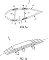
- Figure 1a is a cross-sectional view of a wind turbine rotor blade 10.
- the blade has an outer shell, which is fabricated from two half shells: a windward shell 11a and a leeward shell 11b.
- the shells 11a and 11b are moulded from glass-fibre reinforced plastic (GRP).
- GRP glass-fibre reinforced plastic
- Parts of the outer shell 11 are of sandwich panel construction and comprise a core 12 of lightweight foam (e.g. polyurethane), which is sandwiched between inner 13 and outer 14 GRP layers or 'skins'.
- foam e.g. polyurethane
- the blade 10 comprises a first pair of spar caps 15a and 15b and a second pair of spar caps 16a, 16b.
- the respective pairs of spar caps 15a and 15b, 16a and 16b are arranged between sandwich panel regions of the shells 11a and 11b.
- One spar cap 15a, 16a of each pair is integrated with the windward shell 11a and the other spar cap 15b, 16b of each pair is integrated with the leeward shell 11b.
- the spar caps of the respective pairs are mutually opposed and extend longitudinally along the length of the blade 10.
- a first longitudinally-extending shear web 17a bridges the first pair of spar caps 15a and 15b and a second longitudinally-extending shear web 17b bridges the second pair of spar caps 16a and 16b.
- the spar caps 15a and 15b and 16a and 16b in particular transfer tensile and compressive bending loads, whilst the shear webs 17a and 17b transfer shear stresses in the blade 10.
- Each spar cap 15a and 15b and 16a and 16b has a substantially rectangular cross section and is made up of a stack of pre-fabricated reinforcing strips 18.
- the strips 18 are pultruded strips of carbon-fibre reinforced plastic (CFRP), and are substantially flat and of rectangular cross section.
- the number of strips 18 in the stack depends upon the thickness of the strips 18 and the required thickness of the shells 11a and 11b, but typically the strips 18 each have a thickness of a few millimetres and there may be between three and twelve strips in the stack.
- the strips 18 have a high tensile strength, and hence have a high load bearing capacity.
- Figure 1b illustrates in perspective view a spar cap 15a in isolation.
- the strips 18 of the spar cap 15a are of decreasing lengths moving from the lower-most strip 18 to the uppermost strip 18, and the ends 19 of the strips 18 are staggered along the length of the spar cap 15a.
- Each end 19 is tapered, so as to facilitate stress transfer between strips 18 in the stack and to reduce stress concentrations when the stack is overlaid with materials forming the inner skin 13.
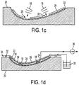
- FIG. 1c this shows a mould 20 for a half shell of a wind turbine blade in cross-section.
- a glass-fibre layer 22 is arranged in the mould 20 to form the outer skin 14 of the blade 10.
- Three elongate panels 24 of polyurethane foam are arranged on top of the glass-fibre layer 22 to form the sandwich panel cores 12 referred to above.
- the foam panels 24 are spaced apart relative to one another to define a pair of channels 26 in between.
- a plurality of pultruded strips 18 of CFRP as described above with reference to Figure 1a , are stacked in the respective channels 26. Three strips 18 are shown in each stack in this example, but there may be any number of strips 18 in a stack.
- a second glass-fibre layer 28 is arranged on top of the foam panels 24 and the stacks of pultruded strips 18.
- the second glass-fibre layer 28 forms the inner skin 13 of the blade 10.
- vacuum bagging film 30 is placed over the mould 20 to cover the layup.
- Sealing tape 32 is used to seal the vacuum bagging film 30 to a flange 34 of the mould 20.
- a vacuum pump 36 is used to withdraw air from the sealed region between the mould 20 and the vacuum bagging film 30, and resin 38 is supplied to the sealed region. The resin 38 infuses between the various laminate layers and fills any gaps in the laminate layup.
- the mould 20 is heated whilst the vacuum is maintained to cure the resin 38 and bond the various layers together to form the half shell of the blade.
- the other half shell is made according to an identical process. Adhesive is then applied along the leading and trailing edges of the shells and the shells are bonded together to form the complete blade.
- spar caps 15a and 15b and 16a and 16b within the structure of the outer shells 11a and 11b avoids the need for a separate spar cap such as a reinforcing beam, which is typically bonded to an inner surface of the shell in many conventional wind turbine blades.
- a separate spar cap such as a reinforcing beam
- Other examples of rotor blades having spar caps integral with the shell are described in EP 1 520 983 , WO 2006/082479 and UK Patent Application GB 2497578 .
- the CFRP pultruded strips 18 extend along the majority of the length of the wind turbine blade 10. Modern wind turbine blades may be in excess of eighty metres long, and so it will be appreciated that these strips are very long and heavy.
- the length and weight of the strips presents challenges relating to the manufacture of the blades, and relating to the handling and transportation of the strips.
- the present invention aims to address these challenges by providing a convenient method of manufacturing this type of wind turbine blade, and by providing apparatus for use in the method.
- FR2405815 describes a device for cutting elastic or plastics webs which has cutter which is displaceable across the web and has a cutting edge inclined at an acute angle towards the surface of the web.
- WO2011/092486 describes a method of processing a fibrous reinforcement where a series of projections and recesses are formed in the fibrous reinforcement in plan view.
- WO2006/015598 describes a method of cutting off laminate layers for use in a fibre-reinforced laminate object.
- the invention resides in a method of making a longitudinal reinforcing structure for a wind turbine blade according to claim 1.
- the invention therefore provides a method in which a first strip can be divided from a master strip whilst chamfers are simultaneously created at a trailing end of the first strip and a leading end of the master strip. In this way, a single process step can be used to divide and chamfer the strips, which increases the speed of the manufacturing process, and reduces the space required.
- the dividing region may taper through the thickness of the master strip moving in a direction from the first surface towards the second surface of the master strip such that a longitudinal extent of the dividing region is narrower at the second surface of the master strip than at the first surface.
- the chamfered surface may taper in a similar fashion.
- a tapered chamfer is particularly advantageous, as it provides particularly effective stress transfer between strips in the longitudinal reinforcing structure.
- the method comprises grinding the master strip to remove material from the dividing region.
- the method comprises moving a grinding device such as a grinding drum through the thickness of the master strip from the first surface of the master strip towards the second surface of the master strip. Grinding the master strip is a quick and inexpensive method of removing material, and causes minimal damage to the strips.
- the method comprises moving the grinding device in a curved path relative to the master strip so as to form curved chamfers at the trailing end of the first strip and at the new leading end of the master strip.
- Curved chamfers are particularly effective in providing stress transfer between strips in the longitudinal reinforcing structure, and moving the grinding device in a curved path controls the resulting curve of the chamfer, such that the curve can be tailored as required.
- the method may comprise further shaping the chamfer at the trailing end of the first strip by removing material from a shaping region of the first strip.
- the method may comprise further shaping the chamfer at the new leading end of the master strip by removing material from a shaping region of the master strip. In this way, if a chamfer produced by the initial dividing and chamfering process is not of the required shape, the chamfer can be further shaped until the required shape is achieved.
- the method may comprise using the grinding device to further shape the chamfers at the trailing end of the first strip and at the new leading end of the master strip.
- the same grinding device can be used for the initial dividing and chamfering process, and for the subsequent shaping process, reducing the manufacturing time, and the space required.
- the method may comprise moving the new leading end of the master strip in the feed direction before removing material from the shaping region of the master strip.
- the shaping region at the new leading end of the master strip can be moved into the space previously occupied by the shaping region at the trailing end of the first strip, so that the shaping process can take place in the same space.
- the movement range of the grinding device need only be equal to the length of a single chamfer.
- the method may comprise creating a chamfer in a leading end of the first strip.
- the method may comprise creating a chamfer in a leading end of the master strip before dividing the master strip transversely to form the first strip, and the chamfered leading end of the master strip may become the leading end of the first strip when the master strip is divided.
- the method may further comprise feeding the master strip along a feed path in a feed direction towards a dividing station at which the master strip is divided and chamfered.
- the dividing and chamfering process may be part of a larger manufacturing process, and the master strip may be fed from earlier processing or storage stations upstream of the dividing and chamfering station.
- the method may further comprise feeding the first strip along the feed path in the first direction away from the dividing station.
- the divided first strip may be fed to later processing or storage stations downstream of the dividing and chamfering station.
- the method may comprise feeding a first predetermined length of the master strip past a dividing and chamfering device associated with the dividing station such that the dividing region of the master strip is located adjacent the dividing and chamfering device, wherein the first predetermined length is substantially the length of the first strip.
- the method may further comprise dividing the master strip transversely to form a second strip, wherein the new chamfered leading end of the master strip becomes a leading end of the second strip and the step of dividing the master strip to form the second strip also serves to create a chamfer at a trailing end of the second strip and a chamfer in an adjacent new leading end of the master strip.
- Further strips may also be formed in the same manner, such that the master strip is divided into a plurality of strips having chamfered leading and trailing ends.
- the method may comprise feeding a second predetermined length of the master strip past the dividing and chamfering device before dividing the master strip to form the second strip, wherein the second predetermined length is substantially the length of the second strip.
- the second predetermined length may be substantially equal to the first predetermined length such that the first and second strips are substantially the same length.
- the first and second predetermined lengths may be different, such that the second strip is shorter than the first strip or vice versa.
- the method may comprise successively feeding predetermined lengths of the master strip past the dividing and chamfering apparatus and dividing and chamfering the master strip to form a plurality of strips of substantially the same length or of differing lengths.
- the method may further comprise cutting an end region of the or each strip longitudinally thereby to narrow said end so that the strip(s) can be accommodated in a relatively narrow end of a wind turbine blade.
- the method may comprising stacking the first strip with one or more similar strips to form the longitudinal reinforcing structure for a wind turbine blade.
- the strips may be stacked inside a wind turbine blade mould, or the strips may be stacked outside a wind turbine blade mould and the stack of strips may be transferred into the wind turbine blade mould.
- the method may further comprise integrating the strips in the stack by means of resin between the adjacent strips.
- the invention also extends to a method of making a wind turbine blade according to claim 15.
- An apparatus for making a longitudinal reinforcing structure for a wind turbine blade may comprise: a feed station configured to feed an elongate master strip of reinforcing material along a feed path in a feed direction, and a dividing station located on the feed path downstream from the feed station, the dividing station comprising a dividing and chamfering device.
- the feed station is configured to feed the master strip past the dividing and chamfering device, and the dividing and chamfering device is configured to divide the master strip transversely into a plurality of shorter strips having chamfered ends.
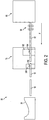
- Figure 2 illustrates an apparatus 50 used in the manufacture of wind turbine blades of the type described above by way of introduction to the present invention. More specifically, the apparatus 50 is used for making spar caps comprising a stack of strips of polymeric reinforcing material, as described by way of introduction.
- the manufacturing apparatus 50 comprises a feed station 60 for dispensing an elongate master strip 62 of polymeric reinforcing material along a path in a feed direction as indicated by the horizontal arrow F in Figure 2 .
- the master strip 62 is a pultruded length of carbon-fibre reinforced plastic (CFRP), which is formed into a coil.
- CFRP carbon-fibre reinforced plastic
- the master strip 62 has a length several times the length of the spar caps 15a, 15b, 16a, 16b that are to be integrated into the blade 10.
- the spar caps 15a, 15b, 16a, 16b may have a length of approximately 50 metres, whilst the coiled master strip 62 may have a length of approximately 250 metres or more.
- the master strip 62 is fed by a feeding means 64 from the feed station 60 to a dividing station 70 arranged inline with the feed station 60.
- the master strip 62 is divided into smaller strip sections 18 that form the strips 18 that are subsequently stacked to form the spar caps 15a, 15b, 16a, 16b.
- the strips 18 are shaped so that they can be accommodated in the relatively narrow tip region of the blade. Specifically, the strips 18 are cut in a longitudinal direction such that they become narrower towards one end when viewed in plan view. This process will be described in more detail later.
- the strips 18 are then fed on to a mould tool, in this case a wind turbine blade mould 20, where the strips 18 are stacked and integrated to form the spar caps 15a, 15b, 16a, 16b.
- the dividing station 70 comprises a dividing and chamfering apparatus 100 and a cutting apparatus 200 for narrowing the ends of the strips.
- the dividing and chamfering apparatus 100 is arranged in an up-stream position (i.e. towards the feed station 60) and is shown in more detail in Figures 3 and 4 , whilst the cutting apparatus 200 is arranged in a down-stream position (i.e. towards the wind turbine mould 20), and is shown in Figures 5 and 6 .
- Feeding means such as driven conveyors (not shown) feed the master strip 62 in to the dividing and chamfering apparatus 100, then feed the divided strips 18 from the dividing and chamfering apparatus 100 to the cutting apparatus 200, and finally feed the cut strips 18 onwards towards the blade mould 20.
- driven conveyors not shown
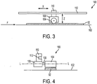
- FIG 3 is a side view of the dividing and chamfering apparatus 100 whilst Figure 4 is an end view of the apparatus 100, i.e. as viewed along the feed direction F.
- the dividing and chamfering apparatus 100 comprises a platform 102 for supporting the master strip 62 during the dividing process.
- a dividing and chamfering device in the form of a grinding drum 104 is arranged above the platform 102.
- the grinding drum 104 has a diameter of approximately 150 mm, and is rotatable on a drive shaft 105 ( Figure 4 ) about a longitudinal axis L perpendicular to the feed direction F, indicated on Figure 4 .
- Rotation of the grinding drum 104 is driven by a drive motor 106 that is coupled to the grinding drum 104 by the drive shaft 105.
- the grinding drum 104, drive motor 106 and drive shaft 105 are mounted on a carriage 110.
- the carriage 110 is slidably mounted on a rail 112, so that the grinding drum 104 can be displaced back and forth along a direction X indicated on Figure 3 , which is substantially parallel to the feed direction.
- the rail 112 is also movable upwardly and downwardly, towards and away from the master strip 62, such that the grinding drum 104 can be displaced towards and away from the master strip 62 along a direction Z indicated on Figure 3 , i.e. perpendicular to the feed direction F.
- Rotation of the grinding drum 104, and movement of the grinding drum 104 in the X and Z directions, is controlled by means of a feedback system such as one or more servomechanisms.
- the grinding drum 104, rail 112, parts of the drive system 108 and a region of the master strip 62 that is close to the grinding drum 104, are shielded by a casing (not shown in the Figures).
- the casing prevents access to the grinding drum 104 and other moving parts of the apparatus 100 when they are in use, for safety reasons.
- a platform 150 Downstream of the dividing and chamfering apparatus 100 is a platform 150, visible in Figure 6 , that supports the strip 18 as it is moved away from the dividing and chamfering station 100 and towards the cutting apparatus 200.
- the cutting apparatus 200 sits over the end region 150a of the platform 150 to cut the corresponding end region 19 of the strip 18, i.e. to narrow the end region 19 so that it may be accommodated within the narrow tip region of the blade.
- the cutting apparatus 200 comprises a series of clamping mechanisms 202 comprising hydraulic clamps 203.
- the clamps 203 hold the strip 18 in place on the platform 150 during the cutting process.
- a cutting mechanism 204 is arranged above the platform 150.
- the cutting mechanism 204 comprises a circular saw 206, in this case a diamond saw, that can be rotated to cut a strip 18 supported on the platform 150. Rotation of the circular saw 206 is controlled by a motor 208.
- the cutting mechanism 204 is mounted on a rail 210 ( Figure 6 ) that extends longitudinally in the feed direction F, so that the circular saw 206 can be moved longitudinally back and forth in the direction X indicated on Figure 6 .
- the rail 210, and hence the circular saw 206 is movable back and forth across the width of the strip 18 in a transverse direction Y, which is perpendicular to the X and Z directions described earlier. Movement of the circular saw in the X and Y directions is controlled by means of a feedback system such as one or more servomechanisms 212.
- the master strip 62 is fed from the feed station 60 along the feed path in the feed direction F towards the dividing and chamfering apparatus 100.
- the dividing and chamfering apparatus 100 receives the master strip 62 and, as will be described in further detail below, the grinding drum 104 is initially used to create a chamfer in a leading end 63 of the master strip 62 and is subsequently used to divide the master strip 62 into a series of strips 18 each having chamfered leading and trailing ends 19a, 19b.
- the master strip 62 is fed along the feed path F in the feed direction towards the grinding drum 104. Once the leading end 63 of the master strip 62 is located below the drum, the feed process is halted. The grinding drum 104 is then moved in the Z and X directions to define an arcuate path. The drum 104 is moved back and forth across the end of the master strip 62 along the arcuate path and is moved progressively deeper through the thickness of the master strip 62 to create a curved chamfered end surface 63a in the leading end 63 of the master strip 62.
- the path of the grinding drum 104 is controlled by the servomechanisms. In this case, the grinding drum 104 is moved along a substantially parabolic path to create a substantially parabolic chamfered end surface 63a in the master strip 62.
- a predetermined length L of the strip 62 is fed past the grinding drum 104 and the feed process is suspended once again.
- the predetermined length corresponds substantially to the desired length of the strip 18 to be divided out from the master strip 62.
- a dividing region 66 of the master strip 62 is then located beneath the grinding drum 104.
- the master strip 62 will be divided and chamfered by removing material from the dividing region 66.
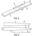
- the dividing region 66 is shown in detail in Figure 8 .
- the dividing region 66 tapers from an upper surface 68a of the master strip 62 to a lower surface 68b of the master strip 62.
- the dividing region 66 has a longitudinal extent L' which is approximately 1 m
- the dividing region 66 has a longitudinal extent L" which is less than the longitudinal extent L', and which, in this case, is approximately 25 mm.
- the master strip 62 is ready to be divided.
- the grinding drum 104 is rotated and is moved downwardly in the Z direction towards an upper surface 68a of the master strip 62 to begin grinding, as shown in Figure 7b .
- the drum 104 is moved back and forth along a parabolic path, as indicated in Figure 7c .
- the parabolic path shapes a ground surface 69 in the master strip 62.
- the grinding drum 104 is moved downwardly in the Z direction to grind deeper into the master strip 62, as shown in Figure 7d .
- the grinding drum 104 grinds through the entire thickness of the strip. Referring to Figure 7e , this process creates a first strip 18 having a chamfered leading end 19a, and a chamfered trailing end 19b.
- the dividing and chamfering process described above also simultaneously creates a chamfered surface 63a at a new leading end 63 of the remaining length of the master strip 62.
- the process then essentially repeats, and a subsequent predetermined length of the new master strip 62 is fed past the grinding drum 104 and the grinding drum 104 is then used to divide the master strip 62 to create a second strip 18.
- the second strip 18 already has a chamfered leading end 19a due to the dividing and chamfering process described above that creates the first strip 18.
- the subsequent dividing and chamfering process creates a chamfered end surface 19c at the trailing end 19b of the second strip 18 and again at the leading end 63 of the remaining length of the master strip 62.
- the process continues in this manner to create a succession of strips 18 each having chamfered leading and trailing ends 19a, 19b until the master strip 62 has been depleted.
- each chamfered surface 19c, 63a extends around 50 cm into the strip 18.
- the individual strips 18 are divided from the master strip 62 at the shallowest point of the parabolic curve of the ground surface 69. This is particularly advantageous as it means that the strips 18 decrease to zero thickness at their ends. This zero thickness is particularly effective in ensuring stress transfer between the stacked strips 18 in the finished spar cap 15a, 15b, 16a, 16b.
- the strip 18 is fed along the platform 150 to the cutting apparatus 200 of Figures 5 and 6 where the longitudinal edges of a leading end 19a of the strip 18 are cut in order to narrow the end portion so that the strip 18 can be accommodated in the relatively narrow tip region of the blade.
- the strip 18 is arranged in the required position on the platform 150 alongside a first longitudinal edge of the strip 18, and the clamps 203 are activated to fix the strip 18 in place.
- the circular saw 206 is rotated by the motor 208 and is moved steadily in the X direction to cut the strip. As the circular saw 206 is moved in the X direction it is also moved in the Y direction, towards a centre of the strip 18. Movement of the circular saw 206 is controlled by the servo mechanisms 212.
- the circular saw 206 is then moved in the Y direction and positioned alongside the second longitudinal edge of the strip 18. The circular saw 206 is then moved back in the X direction to cut the second longitudinal edge on a return pass. Alternatively, the circular saw 206 may first be moved backward in the X direction to its initial position, then moved in the Y direction towards the second longitudinal edge of the strip and finally forward in the X direction to cut the second edge on a second forward pass.
- Figure 9 illustrates a typical shape of the end region 19a of the strip 18 after cutting.
- the strip 18 At the trailing end 19b of the strip 18, the strip 18 has a width w of approximately 200 mm.
- the strip 18 has a width w' of approximately 75 mm.
- the narrowed part of the strip 18 comprises approximately the final 3.5 m section of the strip 18, as indicated by the arrow d in Figure 9 .
- the clamps 203 are removed, and the strip 18 is fed onwards towards the blade mould 20 for stacking and integration into the wind turbine blade 10.
- the apparatus 50 described provides a simple, mechanised method of processing an elongate master strip 62 into a plurality of smaller strips 18 to make an elongate reinforcing structure such as a spar cap 15a, 15b, 16a, 16b.
- the strips 18 can be simultaneously divided and chamfered by virtue of the dividing and chamfering apparatus 100, and separate dividing and chamfering stages are not required.
- two strip ends can be chamfered simultaneously.
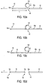
- Figures 10a to 10d illustrate an alternative dividing and chamfering process.
- the first chamfered surface 63a is formed in the leading end 63 of the master strip 62 as has already been described.
- the master strip 62 is then advanced in the feed direction F until a predetermined length L of the strip 62 has been fed past the grinding drum 104 and the feed process is suspended.
- the predetermined length corresponds substantially to the desired length of the strip 18 to be divided out from the master strip 62.
- the dividing region 66 of the master strip 62 is located beneath the grinding drum 104.
- the grinding drum 104 is rotated and is moved downwardly in the Z direction towards the upper surface 68a of the master strip 62 to begin grinding material away from the dividing region 66.
- the grinding drum 104 is moved further downward in the Z direction to grind deeper into the master strip 62, as shown in Figure 10b . Eventually, the grinding drum 104 grinds through the entire thickness of the master strip 62.
- the drum 104 moves only downwardly in the Z direction, and is not moved back and forth in the X direction during the dividing and chamfering process.
- the curved surface of the drum 104 shapes the ground surface 69 of the master strip 62 to form the chamfered end surfaces 19c, 63a.
- the shapes of the chamfered end surfaces 19c, 63a are therefore complementary to the shape of the drum 104.
- the process divides the master strip 62 so as to create a first strip 18 having a chamfered leading end 19a, and a chamfered trailing end 19b.
- the dividing and chamfering process described above also simultaneously creates a chamfer 63a at a new leading end 63 of the remaining length of the master strip 62.
- the process then repeats and the grinding drum 104 is used to divide and chamfer the master strip 62 again to create a second strip 18 having a chamfered leading end 19a, and a chamfered trailing end 19b, and to create a chamfered surface 63a at the leading end 63 of the remaining length of the master strip 62.
- the process continues in this manner to create a succession of strips 18 each having chamfered leading and trailing ends 19a, 19b until the master strip 62 has been depleted.
- the strips 18 may then be fed onwards for cutting in the manner already described.
- Figures 11a to 11g illustrate another dividing and chamfering process.
- the initial stages of this process, shown in Figures 11a to 11c are similar to the stages described in relation to Figures 10a to 10c .
- a dividing region 66 of the master strip 62 is firstly located beneath the grinding drum 104.
- the drum 104 is lowered towards the upper surface 68a of the master strip 62 to remove material from the dividing region 66 as shown in Figure 11b . Grinding continues until the drum 104 has ground all the way through the master strip 62 as shown in Figure 11c .
- the drum 104 does not move in the X direction at this stage, but moves only downwardly in the Z direction.
- the curved surface of the drum 104 shapes the ground surface 69 in the master strip 62 to form the chamfered end surface 19c in the trailing end 19b of the divided strip 18 and the chamfered end surface 63a in the leading end 63 of the remaining master strip 62, as has been described.
- This process differs from the process illustrated in Figures 10a to 10d in that once the master strip 62 has been divided, the chamfered end surface 19c at the trailing end 19b of the strip 18 and the chamfered end surface 63a at the leading end 63 of the remaining master strip 62 are shaped further so as to make the chamfers at the chamfered end surfaces 19b, 63 more shallow.
- the chamfered end surfaces 19c, 63a are shaped by using the grinding drum 104 to remove material from a shaping region 67 that incorporates the respective chamfered end surfaces 19c, 63a.
- the shaping region 67 in the vicinity of the chamfered end surface 19c of the divided strip 18 is shown in detail in Figure 12 .
- the shaping region 67 tapers from an upper surface of the strip 18 to a lower surface of the strip 18 to define a taper that is shallower than the taper of the chamfered end surface 19c.
- the shaping region 67 has a longitudinal extent L'" which is approximately 0.5 m.
- the chamfered end surfaces 19c, 63a are shaped one-at-a-time to create relatively shallow chamfers at the ends of the strips 18, 62, as will now be described.
- the chamfered end surface 19c at the trailing end 19b of the strip 18 is shaped by removing material from a shaping region 67 near the chamfered end surface 19c.
- the divided strip 18 and master strip 62 remain in place.
- the drum 104 is displaced in the X direction towards one end of the shaping region 67, to a left-most position as shown in Figure 11d .
- the drum 104 is moved back and forth along an arcuate path that ends at the opposite end of the shaping region 67, with the drum 104 in its right-most position, as shown in Figure 11e .
- the shape of the arcuate path defines the material that is removed from the shaping region 67, and hence defines the final shape of the chamfered end surface 19c of the divided strip 18.
- the divided strip 18 is moved onwards in the feed direction F for further processing.
- the chamfered end surface 63a at the leading end 63 of the remaining master strip 62 is shaped by removing material from a shaping region 67 near that chamfered end surface 63a.
- the remaining master strip 62 is fed in the feed direction F, so that a shaping region 67 of the remaining master strip 62 is located beneath the grinding drum 104.
- the grinding drum 104 is positioned at one end of the shaping region 67 in its right-most position as shown in Figure 11f .
- the drum 104 is then rotated and lowered onto the upper surface 68a of the master strip 62.
- the drum 104 is moved along an arcuate path that ends at the opposite end of the shaping region 67, with the drum 104 in its left-most position, as shown in Figure 11g , so as to shape the chamfered end surface 63a of the master strip 62 to create a relatively shallow chamfer.
- the distance 300 between the left-most position of the drum 104 (illustrated in Figures 11d and 11g ) and the right-most position of the drum 104 (illustrated in Figures 11e and 11f ) need only be equal to the length of a single chamfered surface 19c, 63a, which in this example is approximately 0.5 m. It will be appreciated that reducing the movement of the drum 104 to a distance that is equal to the length of a single chamfered surface, rather than the length of two chamfered surfaces, represents a significant saving in the space required by the dividing and chamfering apparatus, particularly if even shallower chamfers are required.
- the dividing, chamfering and further shaping process can be repeated to produce more divided strips 18.
- the drum need not be moved in an arcuate motion to form a parabolic chamfered surface, but may be moved in any manner to grind a chamfered surface of any shape.
- the drum may be moved in any suitable manner to further shape the end surfaces.
- the drum may begin in an upper position, such that it is moved downwardly from the upper surface of the strip to the lower surface of the strip, as has been described with reference to Figures 11d to 11g , or the drum may begin in a lower position, such that it is moved upwardly from the lower surface of the strip to the upper surface of the strip.
- the drum may also begin in an intermediate position.
- the drum is moved back-and-forth along the arcuate path with pressure applied to the strip in the Z direction.
- the dividing and chamfering process begins with grinding drum being moved in the arcuate motion illustrated in Figures 11d and 11e , such that the grinding drum forms a shallow chamfer in the trailing end of the first strip whilst simultaneously dividing the first strip from the master strip, and forming a steep chamfer in the leading end of the master strip.
- the steep chamfer formed in the leading end of the master strip may then be shaped further as illustrated in Figures 11f and 11g .
- the master strip need not be divided and chamfered by grinding, but may be divided and chamfered by any other suitable means, such as, for example, laser cutting.
- the dividing and chamfering device need not be a grinding drum, but may be any suitable device, such as a laser.
- Additional processing stages may be added at any stage of the manufacturing process. If the cutting stage is not required, the cutting process may be omitted.
- the strips need not be fed directly to the mould tooling after processing, but may be fed for example to further processing areas, or to a storage area.
- the mould tooling need not be a blade mould, but may be a mould suitable for forming spar caps separately, for later integration into wind turbine blades.
Landscapes
- Engineering & Computer Science (AREA)
- Mechanical Engineering (AREA)
- Chemical & Material Sciences (AREA)
- Composite Materials (AREA)
- Life Sciences & Earth Sciences (AREA)
- Sustainable Development (AREA)
- Sustainable Energy (AREA)
- Combustion & Propulsion (AREA)
- General Engineering & Computer Science (AREA)
- Grinding And Polishing Of Tertiary Curved Surfaces And Surfaces With Complex Shapes (AREA)
- Wind Motors (AREA)
- Structures Of Non-Positive Displacement Pumps (AREA)
Description
- The present invention relates to wind turbine blades and to methods of manufacturing wind turbine blades. More specifically, the present invention relates to wind turbine blades that include a stack of load-bearing reinforcing strips integrated within the structure of the shell.
-
Figure 1a is a cross-sectional view of a windturbine rotor blade 10. The blade has an outer shell, which is fabricated from two half shells: awindward shell 11a and aleeward shell 11b. Theshells core 12 of lightweight foam (e.g. polyurethane), which is sandwiched between inner 13 and outer 14 GRP layers or 'skins'. - The
blade 10 comprises a first pair ofspar caps spar caps spar caps shells spar cap windward shell 11a and theother spar cap leeward shell 11b. The spar caps of the respective pairs are mutually opposed and extend longitudinally along the length of theblade 10. - A first longitudinally-extending
shear web 17a bridges the first pair ofspar caps shear web 17b bridges the second pair ofspar caps shear webs rotating blade 10 to the hub of the wind turbine. The spar caps 15a and 15b and 16a and 16b in particular transfer tensile and compressive bending loads, whilst theshear webs blade 10. - Each
spar cap strips 18 are pultruded strips of carbon-fibre reinforced plastic (CFRP), and are substantially flat and of rectangular cross section. The number ofstrips 18 in the stack depends upon the thickness of thestrips 18 and the required thickness of theshells strips 18 each have a thickness of a few millimetres and there may be between three and twelve strips in the stack. Thestrips 18 have a high tensile strength, and hence have a high load bearing capacity. -
Figure 1b illustrates in perspective view aspar cap 15a in isolation. Thestrips 18 of thespar cap 15a are of decreasing lengths moving from thelower-most strip 18 to theuppermost strip 18, and theends 19 of thestrips 18 are staggered along the length of thespar cap 15a. Eachend 19 is tapered, so as to facilitate stress transfer betweenstrips 18 in the stack and to reduce stress concentrations when the stack is overlaid with materials forming theinner skin 13. - The
blade 10 is made using a resin-infusion process as will now be described by way of example with reference toFigures 1c and 1d . Referring toFigure 1c , this shows amould 20 for a half shell of a wind turbine blade in cross-section. A glass-fibre layer 22 is arranged in themould 20 to form theouter skin 14 of theblade 10. Threeelongate panels 24 of polyurethane foam are arranged on top of the glass-fibre layer 22 to form thesandwich panel cores 12 referred to above. Thefoam panels 24 are spaced apart relative to one another to define a pair ofchannels 26 in between. A plurality ofpultruded strips 18 of CFRP, as described above with reference toFigure 1a , are stacked in therespective channels 26. Threestrips 18 are shown in each stack in this example, but there may be any number ofstrips 18 in a stack. - Referring to
Figure 1d , once thestrips 18 have been stacked, a second glass-fibre layer 28 is arranged on top of thefoam panels 24 and the stacks of pultruded strips 18. The second glass-fibre layer 28 forms theinner skin 13 of theblade 10. Next,vacuum bagging film 30 is placed over themould 20 to cover the layup.Sealing tape 32 is used to seal thevacuum bagging film 30 to aflange 34 of themould 20. Avacuum pump 36 is used to withdraw air from the sealed region between themould 20 and thevacuum bagging film 30, andresin 38 is supplied to the sealed region. Theresin 38 infuses between the various laminate layers and fills any gaps in the laminate layup. Oncesufficient resin 38 has been supplied to themould 20, themould 20 is heated whilst the vacuum is maintained to cure theresin 38 and bond the various layers together to form the half shell of the blade. The other half shell is made according to an identical process. Adhesive is then applied along the leading and trailing edges of the shells and the shells are bonded together to form the complete blade. - The integration of the
spar caps outer shells EP 1 520 983 ,WO 2006/082479 and UK Patent ApplicationGB 2497578 - The
CFRP pultruded strips 18 extend along the majority of the length of thewind turbine blade 10. Modern wind turbine blades may be in excess of eighty metres long, and so it will be appreciated that these strips are very long and heavy. The length and weight of the strips presents challenges relating to the manufacture of the blades, and relating to the handling and transportation of the strips. The present invention aims to address these challenges by providing a convenient method of manufacturing this type of wind turbine blade, and by providing apparatus for use in the method. -
FR2405815 WO2011/092486 describes a method of processing a fibrous reinforcement where a series of projections and recesses are formed in the fibrous reinforcement in plan view.WO2006/015598 describes a method of cutting off laminate layers for use in a fibre-reinforced laminate object. - Against this background, and from a first aspect, the invention resides in a method of making a longitudinal reinforcing structure for a wind turbine blade according to claim 1.
- The invention therefore provides a method in which a first strip can be divided from a master strip whilst chamfers are simultaneously created at a trailing end of the first strip and a leading end of the master strip. In this way, a single process step can be used to divide and chamfer the strips, which increases the speed of the manufacturing process, and reduces the space required.
- The dividing region may taper through the thickness of the master strip moving in a direction from the first surface towards the second surface of the master strip such that a longitudinal extent of the dividing region is narrower at the second surface of the master strip than at the first surface. In this way, the chamfered surface may taper in a similar fashion. A tapered chamfer is particularly advantageous, as it provides particularly effective stress transfer between strips in the longitudinal reinforcing structure.
- The method comprises grinding the master strip to remove material from the dividing region. In particular, the method comprises moving a grinding device such as a grinding drum through the thickness of the master strip from the first surface of the master strip towards the second surface of the master strip. Grinding the master strip is a quick and inexpensive method of removing material, and causes minimal damage to the strips.
- The method comprises moving the grinding device in a curved path relative to the master strip so as to form curved chamfers at the trailing end of the first strip and at the new leading end of the master strip. Curved chamfers are particularly effective in providing stress transfer between strips in the longitudinal reinforcing structure, and moving the grinding device in a curved path controls the resulting curve of the chamfer, such that the curve can be tailored as required.
- The method may comprise further shaping the chamfer at the trailing end of the first strip by removing material from a shaping region of the first strip. Alternatively or additionally, the method may comprise further shaping the chamfer at the new leading end of the master strip by removing material from a shaping region of the master strip. In this way, if a chamfer produced by the initial dividing and chamfering process is not of the required shape, the chamfer can be further shaped until the required shape is achieved.
- The method may comprise using the grinding device to further shape the chamfers at the trailing end of the first strip and at the new leading end of the master strip. In this way, the same grinding device can be used for the initial dividing and chamfering process, and for the subsequent shaping process, reducing the manufacturing time, and the space required.
- To reduce the required space still further, the method may comprise moving the new leading end of the master strip in the feed direction before removing material from the shaping region of the master strip. In this way, the shaping region at the new leading end of the master strip can be moved into the space previously occupied by the shaping region at the trailing end of the first strip, so that the shaping process can take place in the same space. This means that the movement range of the grinding device need only be equal to the length of a single chamfer.
- The method may comprise creating a chamfer in a leading end of the first strip. For example, the method may comprise creating a chamfer in a leading end of the master strip before dividing the master strip transversely to form the first strip, and the chamfered leading end of the master strip may become the leading end of the first strip when the master strip is divided.
- The method may further comprise feeding the master strip along a feed path in a feed direction towards a dividing station at which the master strip is divided and chamfered. In this way, the dividing and chamfering process may be part of a larger manufacturing process, and the master strip may be fed from earlier processing or storage stations upstream of the dividing and chamfering station.
- After the master strip has been divided, the method may further comprise feeding the first strip along the feed path in the first direction away from the dividing station. In this way, the divided first strip may be fed to later processing or storage stations downstream of the dividing and chamfering station.
- The method may comprise feeding a first predetermined length of the master strip past a dividing and chamfering device associated with the dividing station such that the dividing region of the master strip is located adjacent the dividing and chamfering device, wherein the first predetermined length is substantially the length of the first strip.
- The method may further comprise dividing the master strip transversely to form a second strip, wherein the new chamfered leading end of the master strip becomes a leading end of the second strip and the step of dividing the master strip to form the second strip also serves to create a chamfer at a trailing end of the second strip and a chamfer in an adjacent new leading end of the master strip. Further strips may also be formed in the same manner, such that the master strip is divided into a plurality of strips having chamfered leading and trailing ends.
- In this case, the method may comprise feeding a second predetermined length of the master strip past the dividing and chamfering device before dividing the master strip to form the second strip, wherein the second predetermined length is substantially the length of the second strip. The second predetermined length may be substantially equal to the first predetermined length such that the first and second strips are substantially the same length. Alternatively, the first and second predetermined lengths may be different, such that the second strip is shorter than the first strip or vice versa.
- The method may comprise successively feeding predetermined lengths of the master strip past the dividing and chamfering apparatus and dividing and chamfering the master strip to form a plurality of strips of substantially the same length or of differing lengths.
- The method may further comprise cutting an end region of the or each strip longitudinally thereby to narrow said end so that the strip(s) can be accommodated in a relatively narrow end of a wind turbine blade.
- The method may comprising stacking the first strip with one or more similar strips to form the longitudinal reinforcing structure for a wind turbine blade. The strips may be stacked inside a wind turbine blade mould, or the strips may be stacked outside a wind turbine blade mould and the stack of strips may be transferred into the wind turbine blade mould.
- The method may further comprise integrating the strips in the stack by means of resin between the adjacent strips.
- The invention also extends to a method of making a wind turbine blade according to claim 15.
- An apparatus for making a longitudinal reinforcing structure for a wind turbine blade may comprise: a feed station configured to feed an elongate master strip of reinforcing material along a feed path in a feed direction, and a dividing station located on the feed path downstream from the feed station, the dividing station comprising a dividing and chamfering device. The feed station is configured to feed the master strip past the dividing and chamfering device, and the dividing and chamfering device is configured to divide the master strip transversely into a plurality of shorter strips having chamfered ends.
-
Figures 1a to 1d have already been described above by way of background to the invention. In order that embodiments of the invention might be more readily understood, reference will now be made, by way of example only, to the accompanying drawings, in which: -
Figure 2 is a schematic view of manufacturing apparatus including a dividing and chamfering apparatus forming an embodiment of the invention; -
Figure 3 is a side view of the dividing and chamfering apparatus ofFigure 2 ; -
Figure 4 is a front view of the dividing and chamfering apparatus ofFigure 3 ; -
Figure 5 is a front view of cutting apparatus forming part of the manufacturing apparatus ofFigure 2 ; -
Figure 6 is a plan view of the cutting apparatus ofFigure 5 ; -
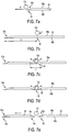
Figures 7a to 7e are schematic views of a strip for a spar cap of a wind turbine blade being divided and chamfered by the apparatus ofFigures 3 and 4 ; -
Figure 8 is a perspective view of a dividing region forming part of the strip ofFigures 7a to 7e ; -
Figure 9 is a plan view of a pair of strips for a respective pair of spar caps, which have been tapered longitudinally by the cutting apparatus ofFigures 5 and 6 ; -
Figures 10a to 10d are schematic views of a a wind turbine blade being divided and chamfered by the apparatus ofFigures 3 and 4 according to an another dividing and chamfering method; -
Figures 11a to 11g are schematic views of a wind turbine blade being divided and chamfered by the apparatus ofFigures 3 and 4 according to another alternative method; and -
Figure 12 is a perspective view of a shaping region forming part of the strip ofFigures 11a to 11g . -
Figure 2 illustrates anapparatus 50 used in the manufacture of wind turbine blades of the type described above by way of introduction to the present invention. More specifically, theapparatus 50 is used for making spar caps comprising a stack of strips of polymeric reinforcing material, as described by way of introduction. - Referring to
Figure 2 , themanufacturing apparatus 50 comprises afeed station 60 for dispensing anelongate master strip 62 of polymeric reinforcing material along a path in a feed direction as indicated by the horizontal arrow F inFigure 2 . In this example, themaster strip 62 is a pultruded length of carbon-fibre reinforced plastic (CFRP), which is formed into a coil. Themaster strip 62 has a length several times the length of the spar caps 15a, 15b, 16a, 16b that are to be integrated into theblade 10. For example, the spar caps 15a, 15b, 16a, 16b may have a length of approximately 50 metres, whilst thecoiled master strip 62 may have a length of approximately 250 metres or more. - The
master strip 62 is fed by a feeding means 64 from thefeed station 60 to a dividingstation 70 arranged inline with thefeed station 60. At the dividingstation 70, themaster strip 62 is divided intosmaller strip sections 18 that form thestrips 18 that are subsequently stacked to form the spar caps 15a, 15b, 16a, 16b. Also at the dividingstation 70, thestrips 18 are shaped so that they can be accommodated in the relatively narrow tip region of the blade. Specifically, thestrips 18 are cut in a longitudinal direction such that they become narrower towards one end when viewed in plan view. This process will be described in more detail later. Thestrips 18 are then fed on to a mould tool, in this case a windturbine blade mould 20, where thestrips 18 are stacked and integrated to form the spar caps 15a, 15b, 16a, 16b. - The dividing
station 70 will now be described in further detail. The dividingstation 70 comprises a dividing andchamfering apparatus 100 and acutting apparatus 200 for narrowing the ends of the strips. The dividing andchamfering apparatus 100 is arranged in an up-stream position (i.e. towards the feed station 60) and is shown in more detail inFigures 3 and 4 , whilst thecutting apparatus 200 is arranged in a down-stream position (i.e. towards the wind turbine mould 20), and is shown inFigures 5 and 6 . Feeding means, such as driven conveyors (not shown) feed themaster strip 62 in to the dividing andchamfering apparatus 100, then feed the divided strips 18 from the dividing andchamfering apparatus 100 to thecutting apparatus 200, and finally feed the cut strips 18 onwards towards theblade mould 20. -
Figure 3 is a side view of the dividing andchamfering apparatus 100 whilstFigure 4 is an end view of theapparatus 100, i.e. as viewed along the feed direction F. Referring to these figures, the dividing andchamfering apparatus 100 comprises aplatform 102 for supporting themaster strip 62 during the dividing process. A dividing and chamfering device in the form of a grindingdrum 104 is arranged above theplatform 102. The grindingdrum 104 has a diameter of approximately 150 mm, and is rotatable on a drive shaft 105 (Figure 4 ) about a longitudinal axis L perpendicular to the feed direction F, indicated onFigure 4 . Rotation of the grindingdrum 104 is driven by adrive motor 106 that is coupled to the grindingdrum 104 by thedrive shaft 105. - The grinding
drum 104, drivemotor 106 and driveshaft 105 are mounted on acarriage 110. Thecarriage 110 is slidably mounted on arail 112, so that the grindingdrum 104 can be displaced back and forth along a direction X indicated onFigure 3 , which is substantially parallel to the feed direction. Therail 112 is also movable upwardly and downwardly, towards and away from themaster strip 62, such that the grindingdrum 104 can be displaced towards and away from themaster strip 62 along a direction Z indicated onFigure 3 , i.e. perpendicular to the feed direction F. Rotation of the grindingdrum 104, and movement of the grindingdrum 104 in the X and Z directions, is controlled by means of a feedback system such as one or more servomechanisms. - The grinding
drum 104,rail 112, parts of the drive system 108 and a region of themaster strip 62 that is close to the grindingdrum 104, are shielded by a casing (not shown in the Figures). The casing prevents access to the grindingdrum 104 and other moving parts of theapparatus 100 when they are in use, for safety reasons. - Downstream of the dividing and
chamfering apparatus 100 is aplatform 150, visible inFigure 6 , that supports thestrip 18 as it is moved away from the dividing andchamfering station 100 and towards the cuttingapparatus 200. - Referring to
Figures 5 and 6 , thecutting apparatus 200 sits over theend region 150a of theplatform 150 to cut thecorresponding end region 19 of thestrip 18, i.e. to narrow theend region 19 so that it may be accommodated within the narrow tip region of the blade. - The
cutting apparatus 200 comprises a series of clampingmechanisms 202 comprisinghydraulic clamps 203. Theclamps 203 hold thestrip 18 in place on theplatform 150 during the cutting process. Acutting mechanism 204 is arranged above theplatform 150. Thecutting mechanism 204 comprises acircular saw 206, in this case a diamond saw, that can be rotated to cut astrip 18 supported on theplatform 150. Rotation of thecircular saw 206 is controlled by amotor 208. - The
cutting mechanism 204 is mounted on a rail 210 (Figure 6 ) that extends longitudinally in the feed direction F, so that thecircular saw 206 can be moved longitudinally back and forth in the direction X indicated onFigure 6 . Therail 210, and hence thecircular saw 206, is movable back and forth across the width of thestrip 18 in a transverse direction Y, which is perpendicular to the X and Z directions described earlier. Movement of the circular saw in the X and Y directions is controlled by means of a feedback system such as one or more servomechanisms 212. - Use of the dividing and
chamfering apparatus 100 and thecutting apparatus 200 in dividing, chamfering, and cutting thestrips 18 will now be described. - Referring again to
Figure 2 , in use, themaster strip 62 is fed from thefeed station 60 along the feed path in the feed direction F towards the dividing andchamfering apparatus 100. The dividing andchamfering apparatus 100 receives themaster strip 62 and, as will be described in further detail below, the grindingdrum 104 is initially used to create a chamfer in aleading end 63 of themaster strip 62 and is subsequently used to divide themaster strip 62 into a series ofstrips 18 each having chamfered leading and trailingends strips 18 along the feed direction F, and should not be confused with the terms 'leading' and 'trailing' when used to describe the edges of a wind turbine blade. - The dividing and chamfering process will now be described in detail with reference to
Figures 7a to 7e . Referring first toFigure 7a , themaster strip 62 is fed along the feed path F in the feed direction towards the grindingdrum 104. Once the leadingend 63 of themaster strip 62 is located below the drum, the feed process is halted. The grindingdrum 104 is then moved in the Z and X directions to define an arcuate path. Thedrum 104 is moved back and forth across the end of themaster strip 62 along the arcuate path and is moved progressively deeper through the thickness of themaster strip 62 to create a curvedchamfered end surface 63a in theleading end 63 of themaster strip 62. - The path of the grinding
drum 104 is controlled by the servomechanisms. In this case, the grindingdrum 104 is moved along a substantially parabolic path to create a substantially parabolicchamfered end surface 63a in themaster strip 62. - Once the initial
chamfered surface 63a has been created in theleading end 63 of themaster strip 62, the feed process is continued and themaster strip 62 is advanced in the feed direction F. Referring now toFigure 7b , a predetermined length L of thestrip 62 is fed past the grindingdrum 104 and the feed process is suspended once again. The predetermined length corresponds substantially to the desired length of thestrip 18 to be divided out from themaster strip 62. - Once the predetermined length L of the
master strip 62 has been fed past the grindingdrum 104 and the feed process suspended, a dividingregion 66 of themaster strip 62 is then located beneath the grindingdrum 104. Themaster strip 62 will be divided and chamfered by removing material from the dividingregion 66. - The dividing
region 66 is shown in detail inFigure 8 . The dividingregion 66 tapers from anupper surface 68a of themaster strip 62 to alower surface 68b of themaster strip 62. In this way, at theupper surface 68a of themaster strip 62, the dividingregion 66 has a longitudinal extent L' which is approximately 1 m, while at thelower surface 68b of themaster strip 62, the dividingregion 66 has a longitudinal extent L" which is less than the longitudinal extent L', and which, in this case, is approximately 25 mm. It will therefore be appreciated that the taper of the dividingregion 66, and hence the chamfers 18a, 18b created at theends 19 of thestrip 18 may be relatively shallow in practice, and may be more shallow than they appear in the accompanying figures. - Once located in place, the
master strip 62 is ready to be divided. - The grinding
drum 104 is rotated and is moved downwardly in the Z direction towards anupper surface 68a of themaster strip 62 to begin grinding, as shown inFigure 7b . As material is ground away from the dividingregion 66 of themaster strip 62, thedrum 104 is moved back and forth along a parabolic path, as indicated inFigure 7c . The parabolic path shapes aground surface 69 in themaster strip 62. - As grinding continues, the grinding
drum 104 is moved downwardly in the Z direction to grind deeper into themaster strip 62, as shown inFigure 7d . Eventually, the grindingdrum 104 grinds through the entire thickness of the strip. Referring toFigure 7e , this process creates afirst strip 18 having a chamfered leadingend 19a, and a chamfered trailingend 19b. - Referring still to
Figure 7e , it will be appreciated that the dividing and chamfering process described above also simultaneously creates a chamferedsurface 63a at a newleading end 63 of the remaining length of themaster strip 62. The process then essentially repeats, and a subsequent predetermined length of thenew master strip 62 is fed past the grindingdrum 104 and the grindingdrum 104 is then used to divide themaster strip 62 to create asecond strip 18. Thesecond strip 18 already has a chamfered leadingend 19a due to the dividing and chamfering process described above that creates thefirst strip 18. The subsequent dividing and chamfering process creates achamfered end surface 19c at the trailingend 19b of thesecond strip 18 and again at theleading end 63 of the remaining length of themaster strip 62. The process continues in this manner to create a succession ofstrips 18 each having chamfered leading and trailingends master strip 62 has been depleted. - As the dividing region 66 (
Figure 7c ) is approximately 1 metre in length, it will be appreciated that in this example eachchamfered surface strip 18. - In the dividing and chamfering process described above, the
individual strips 18 are divided from themaster strip 62 at the shallowest point of the parabolic curve of theground surface 69. This is particularly advantageous as it means that thestrips 18 decrease to zero thickness at their ends. This zero thickness is particularly effective in ensuring stress transfer between thestacked strips 18 in thefinished spar cap - Once each
strip 18 has been divided and chamfered, thestrip 18 is fed along theplatform 150 to thecutting apparatus 200 ofFigures 5 and 6 where the longitudinal edges of aleading end 19a of thestrip 18 are cut in order to narrow the end portion so that thestrip 18 can be accommodated in the relatively narrow tip region of the blade. Thestrip 18 is arranged in the required position on theplatform 150 alongside a first longitudinal edge of thestrip 18, and theclamps 203 are activated to fix thestrip 18 in place. Thecircular saw 206 is rotated by themotor 208 and is moved steadily in the X direction to cut the strip. As thecircular saw 206 is moved in the X direction it is also moved in the Y direction, towards a centre of thestrip 18. Movement of thecircular saw 206 is controlled by theservo mechanisms 212. - Once the first angled cut has been made, the
circular saw 206 is then moved in the Y direction and positioned alongside the second longitudinal edge of thestrip 18. Thecircular saw 206 is then moved back in the X direction to cut the second longitudinal edge on a return pass. Alternatively, thecircular saw 206 may first be moved backward in the X direction to its initial position, then moved in the Y direction towards the second longitudinal edge of the strip and finally forward in the X direction to cut the second edge on a second forward pass. -
Figure 9 illustrates a typical shape of theend region 19a of thestrip 18 after cutting. At the trailingend 19b of thestrip 18, thestrip 18 has a width w of approximately 200 mm. At the leading end of thestrip 18, thestrip 18 has a width w' of approximately 75 mm. In this example, the narrowed part of thestrip 18 comprises approximately the final 3.5 m section of thestrip 18, as indicated by the arrow d inFigure 9 . - After the cutting process has been completed, the
clamps 203 are removed, and thestrip 18 is fed onwards towards theblade mould 20 for stacking and integration into thewind turbine blade 10. - In this way, the
apparatus 50 described provides a simple, mechanised method of processing anelongate master strip 62 into a plurality ofsmaller strips 18 to make an elongate reinforcing structure such as aspar cap strips 18 can be simultaneously divided and chamfered by virtue of the dividing andchamfering apparatus 100, and separate dividing and chamfering stages are not required. Furthermore, two strip ends can be chamfered simultaneously. -
Figures 10a to 10d illustrate an alternative dividing and chamfering process. In this process, the firstchamfered surface 63a is formed in theleading end 63 of themaster strip 62 as has already been described. Referring toFigure 10a , themaster strip 62 is then advanced in the feed direction F until a predetermined length L of thestrip 62 has been fed past the grindingdrum 104 and the feed process is suspended. The predetermined length corresponds substantially to the desired length of thestrip 18 to be divided out from themaster strip 62. - Once the predetermined length L of the
master strip 62 has been fed past the grindingdrum 104 and the feed process has been suspended, the dividingregion 66 of themaster strip 62 is located beneath the grindingdrum 104. To divide and chamfer themaster strip 62, the grindingdrum 104 is rotated and is moved downwardly in the Z direction towards theupper surface 68a of themaster strip 62 to begin grinding material away from the dividingregion 66. - As grinding continues, the grinding
drum 104 is moved further downward in the Z direction to grind deeper into themaster strip 62, as shown inFigure 10b . Eventually, the grindingdrum 104 grinds through the entire thickness of themaster strip 62. - In this process, the
drum 104 moves only downwardly in the Z direction, and is not moved back and forth in the X direction during the dividing and chamfering process. In this way, and as seen inFigure 10c , the curved surface of thedrum 104 shapes theground surface 69 of themaster strip 62 to form thechamfered end surfaces chamfered end surfaces drum 104. - Referring now to
Figure 10d , because the grinding is continued until thedrum 104 has ground all the way through themaster strip 62, the process divides themaster strip 62 so as to create afirst strip 18 having a chamfered leadingend 19a, and a chamfered trailingend 19b. The dividing and chamfering process described above also simultaneously creates achamfer 63a at a newleading end 63 of the remaining length of themaster strip 62. - Once the
strip 18 has been formed, the process then repeats and the grindingdrum 104 is used to divide and chamfer themaster strip 62 again to create asecond strip 18 having a chamfered leadingend 19a, and a chamfered trailingend 19b, and to create achamfered surface 63a at theleading end 63 of the remaining length of themaster strip 62. The process continues in this manner to create a succession ofstrips 18 each having chamfered leading and trailingends master strip 62 has been depleted. Thestrips 18 may then be fed onwards for cutting in the manner already described. -
Figures 11a to 11g illustrate another dividing and chamfering process. The initial stages of this process, shown inFigures 11a to 11c , are similar to the stages described in relation toFigures 10a to 10c . As shown inFigure 11a , a dividingregion 66 of themaster strip 62 is firstly located beneath the grindingdrum 104. Thedrum 104 is lowered towards theupper surface 68a of themaster strip 62 to remove material from the dividingregion 66 as shown inFigure 11b . Grinding continues until thedrum 104 has ground all the way through themaster strip 62 as shown inFigure 11c . Thedrum 104 does not move in the X direction at this stage, but moves only downwardly in the Z direction. The curved surface of thedrum 104 shapes theground surface 69 in themaster strip 62 to form thechamfered end surface 19c in the trailingend 19b of the dividedstrip 18 and thechamfered end surface 63a in theleading end 63 of the remainingmaster strip 62, as has been described. - This process differs from the process illustrated in
Figures 10a to 10d in that once themaster strip 62 has been divided, thechamfered end surface 19c at the trailingend 19b of thestrip 18 and thechamfered end surface 63a at theleading end 63 of the remainingmaster strip 62 are shaped further so as to make the chamfers at the chamfered end surfaces 19b, 63 more shallow. - The
chamfered end surfaces drum 104 to remove material from a shapingregion 67 that incorporates the respectivechamfered end surfaces region 67 in the vicinity of thechamfered end surface 19c of the dividedstrip 18 is shown in detail inFigure 12 . The shapingregion 67 tapers from an upper surface of thestrip 18 to a lower surface of thestrip 18 to define a taper that is shallower than the taper of thechamfered end surface 19c. At the upper surface of thestrip 18, the shapingregion 67 has a longitudinal extent L'" which is approximately 0.5 m. - The
chamfered end surfaces strips - First, the
chamfered end surface 19c at the trailingend 19b of thestrip 18 is shaped by removing material from a shapingregion 67 near thechamfered end surface 19c. The dividedstrip 18 andmaster strip 62 remain in place. Thedrum 104 is displaced in the X direction towards one end of the shapingregion 67, to a left-most position as shown inFigure 11d . Thedrum 104 is moved back and forth along an arcuate path that ends at the opposite end of the shapingregion 67, with thedrum 104 in its right-most position, as shown inFigure 11e . The shape of the arcuate path defines the material that is removed from the shapingregion 67, and hence defines the final shape of thechamfered end surface 19c of the dividedstrip 18. - Once the
chamfered end surface 19c of the dividedstrip 18 has been shaped to create a relatively shallow chamfer, the dividedstrip 18 is moved onwards in the feed direction F for further processing. - Next, the
chamfered end surface 63a at theleading end 63 of the remainingmaster strip 62 is shaped by removing material from a shapingregion 67 near thatchamfered end surface 63a. - Referring to
Figure 11f , the remainingmaster strip 62 is fed in the feed direction F, so that a shapingregion 67 of the remainingmaster strip 62 is located beneath the grindingdrum 104. The grindingdrum 104 is positioned at one end of the shapingregion 67 in its right-most position as shown inFigure 11f . Thedrum 104 is then rotated and lowered onto theupper surface 68a of themaster strip 62. Thedrum 104 is moved along an arcuate path that ends at the opposite end of the shapingregion 67, with thedrum 104 in its left-most position, as shown inFigure 11g , so as to shape thechamfered end surface 63a of themaster strip 62 to create a relatively shallow chamfer. - As indicated by the dashed lines in
Figures 11a to 11g , thedistance 300 between the left-most position of the drum 104 (illustrated inFigures 11d and 11g ) and the right-most position of the drum 104 (illustrated inFigures 11e and 11f ) need only be equal to the length of a single chamferedsurface drum 104 to a distance that is equal to the length of a single chamfered surface, rather than the length of two chamfered surfaces, represents a significant saving in the space required by the dividing and chamfering apparatus, particularly if even shallower chamfers are required. - Once the
chamfered end surface 63a of themaster strip 62 has been shaped as required, the dividing, chamfering and further shaping process can be repeated to produce more divided strips 18. - In the embodiments where the grinding drum is moved in the X direction as well as the Z direction, the drum need not be moved in an arcuate motion to form a parabolic chamfered surface, but may be moved in any manner to grind a chamfered surface of any shape.
- In embodiments where the chamfered end surfaces are further shaped after an initial dividing and chamfering process, the drum may be moved in any suitable manner to further shape the end surfaces. For example, the drum may begin in an upper position, such that it is moved downwardly from the upper surface of the strip to the lower surface of the strip, as has been described with reference to
Figures 11d to 11g , or the drum may begin in a lower position, such that it is moved upwardly from the lower surface of the strip to the upper surface of the strip. The drum may also begin in an intermediate position. In preferred embodiments, the drum is moved back-and-forth along the arcuate path with pressure applied to the strip in the Z direction. - Other embodiments of the invention are envisaged that are similar to the embodiment illustrated in
Figures 11a to 11g , but in which the steps illustrated inFigures 11a to 11c are omitted. In this embodiment, the dividing and chamfering process begins with grinding drum being moved in the arcuate motion illustrated inFigures 11d and 11e , such that the grinding drum forms a shallow chamfer in the trailing end of the first strip whilst simultaneously dividing the first strip from the master strip, and forming a steep chamfer in the leading end of the master strip. The steep chamfer formed in the leading end of the master strip may then be shaped further as illustrated inFigures 11f and 11g . - The master strip need not be divided and chamfered by grinding, but may be divided and chamfered by any other suitable means, such as, for example, laser cutting. Thus, the dividing and chamfering device need not be a grinding drum, but may be any suitable device, such as a laser.
- Additional processing stages may be added at any stage of the manufacturing process. If the cutting stage is not required, the cutting process may be omitted.
- The strips need not be fed directly to the mould tooling after processing, but may be fed for example to further processing areas, or to a storage area. The mould tooling need not be a blade mould, but may be a mould suitable for forming spar caps separately, for later integration into wind turbine blades.
Claims (15)
- A method of making a longitudinal reinforcing structure (15a) for a wind turbine blade (10), the method comprising:a. providing an elongate master strip (62) of reinforcing material having substantially flat first and second surfaces, the distance between the first and second surfaces defining the thickness of the master strip; andb. dividing the master strip (62) transversely to form a first strip (18) and a shorter master strip, the respective strips being arranged end to end such that a trailing end of the first strip is located adjacent a new leading end (63) of the master strip; characterised in that:the step of dividing the master strip (62) comprises removing material from a dividing region (66) extending through the entire thickness of the master strip by moving a grinding device such as a grinding drum (104) through the thickness of the master strip (62) from the first surface of the master strip towards the second surface of the master strip, wherein the dividing region is shaped such that a chamfer at the trailing end (19b) of the first strip is created and/or a chamfer (63a) at the new leading end (19a) of the master strip is created when the master strip is divided;the method further comprising moving the grinding device (104) in a curved path relative to the master strip (62) so as to form curved chamfers at the trailing end of the first strip and/or at the new leading end of the master strip.
- The method of Claim 1, wherein the dividing region tapers (66) through the thickness of the master strip (62) moving in a direction from the first surface towards the second surface of the master strip such that a longitudinal extent of the dividing region is narrower at the second surface of the master strip than at the first surface.
- The method of Claim 1 or Claim 2, comprising grinding the master strip (62) to remove material from the dividing region (66).
- The method of any preceding claim, comprising further shaping the chamfer (19b) at the trailing end of the first strip (18) by removing material from a shaping region (67) of the first strip.
- The method of Claim 4, comprising further shaping the chamfer at the new leading end of the master strip (62) by removing material from a shaping region of the master strip.
- The method of Claim 5, comprising using the grinding device (104) to further shape the chamfers at the trailing end of the first strip (18) and at the new leading end of the master strip (62).
- The method of Claim 5 or Claim 6, comprising moving the new leading end of the master strip (62) in a feed direction before removing material from the shaping region (67) of the master strip.
- The method of any preceding claim, further comprising creating a chamfer in a leading end of the first strip (18).
- The method of any preceding claim, further comprising dividing the master strip (62) transversely to form a second strip, wherein the new chamfered leading end of the master strip becomes a leading end of the second strip and the step of dividing the master strip to form the second strip also serves to create a chamfer at a trailing end of the second strip and a chamfer in an adjacent new leading end of the master strip.
- The method of any preceding claim, further comprising stacking the first strip (18) with one or more similar strips to form the longitudinal reinforcing structure for a wind turbine blade.
- The method of Claim 10, wherein the method further comprises stacking the strips (18) inside a wind turbine blade mould (20), or stacking the strips outside a wind turbine blade mould and transferring the stack of strips into the wind turbine blade mould.
- The method of Claim 10 or Claim 11, further comprising integrating the strips (18) in the stack by means of resin between the adjacent strips.
- The method of any preceding claim, further comprising feeding the master strip along a feed path in a feed direction towards a dividing station at which the master strip is divided and chamfered, wherein the grinding device travels over a longitudinal extent in the feed direction, the longitudinal extent being substantially equal to the length of the chamfer at the trailing end of the first strip and/or the length of the chamfer at the new leading end of the master strip.
- The method of any preceding claim, further comprising cutting an end region of the or each strip longitudinally thereby to narrow said end so that the strip(s) can be accommodated in a relatively narrow end of a wind turbine blade.
- A method of making a wind turbine blade comprisinga) providing a plurality of strips (18),b) stacking the strips inside a wind turbine blade mould (20), or stacking the strips outside a wind turbine blade mould and transferring the stack of strips into the wind turbine blade mouldc) arranging other components of a wind turbine blade (10) in the wind turbine blade mould; andd) integrating the components to form the blade;
wherein providing a plurality of strips comprises:a. providing an elongate master strip (62) of reinforcing material having substantially flat first and second surfaces, the distance between the first and second surfaces defining the thickness of the master strip; andb. dividing the master strip (62) transversely to form a first strip (18) and a shorter master strip, the respective strips being arranged end to end such that a trailing end of the first strip is located adjacent a new leading end (63) of the master strip;the step of dividing the master strip (62) comprises removing material from a dividing region (66) extending through the entire thickness of the master strip by moving a grinding device such as a grinding drum (104) through the thickness of the master strip (62) from the first surface of the master strip towards the second surface of the master strip, wherein the dividing region is shaped such that a chamfer at the trailing end (19b) of the first strip is created and/or a chamfer (63a) at the new leading end (19a) of the master strip is created when the master strip is divided; and
moving the grinding device (104) in a curved path relative to the master strip (62) so as to form curved chamfers at the trailing end of the first strip and/or at the new leading end of the master strip.
Priority Applications (1)
| Application Number | Priority Date | Filing Date | Title |
|---|---|---|---|
| EP21186021.8A EP3912804A1 (en) | 2013-11-11 | 2014-11-10 | Wind turbine blades |
Applications Claiming Priority (2)
| Application Number | Priority Date | Filing Date | Title |
|---|---|---|---|
| GB1319848.6A GB2520079A (en) | 2013-11-11 | 2013-11-11 | Wind turbine blades |
| PCT/DK2014/050373 WO2015067279A1 (en) | 2013-11-11 | 2014-11-10 | Wind turbine blades |
Related Child Applications (1)
| Application Number | Title | Priority Date | Filing Date |
|---|---|---|---|
| EP21186021.8A Division EP3912804A1 (en) | 2013-11-11 | 2014-11-10 | Wind turbine blades |
Publications (2)
| Publication Number | Publication Date |
|---|---|
| EP3068614A1 EP3068614A1 (en) | 2016-09-21 |
| EP3068614B1 true EP3068614B1 (en) | 2021-08-18 |
Family
ID=49818414
Family Applications (2)
| Application Number | Title | Priority Date | Filing Date |
|---|---|---|---|
| EP21186021.8A Withdrawn EP3912804A1 (en) | 2013-11-11 | 2014-11-10 | Wind turbine blades |
| EP14796696.4A Active EP3068614B1 (en) | 2013-11-11 | 2014-11-10 | Wind turbine blades |
Family Applications Before (1)
| Application Number | Title | Priority Date | Filing Date |
|---|---|---|---|
| EP21186021.8A Withdrawn EP3912804A1 (en) | 2013-11-11 | 2014-11-10 | Wind turbine blades |
Country Status (7)
| Country | Link |
|---|---|
| US (1) | US10232528B2 (en) |
| EP (2) | EP3912804A1 (en) |
| CN (1) | CN105899351A (en) |
| DK (1) | DK3068614T3 (en) |
| ES (1) | ES2888101T3 (en) |
| GB (1) | GB2520079A (en) |
| WO (1) | WO2015067279A1 (en) |
Families Citing this family (29)
| Publication number | Priority date | Publication date | Assignee | Title |
|---|---|---|---|---|
| US10137542B2 (en) * | 2010-01-14 | 2018-11-27 | Senvion Gmbh | Wind turbine rotor blade components and machine for making same |
| US9384668B2 (en) | 2012-05-09 | 2016-07-05 | Singularity University | Transportation using network of unmanned aerial vehicles |
| US20170028587A1 (en) * | 2015-07-30 | 2017-02-02 | General Electric Company | In-line processing of pre-formed pultruded products for use within a wind turbine rotor blade |
| EP4001111A3 (en) * | 2015-11-10 | 2022-08-17 | Matternet, Inc. | Methods and system for transportation using unmanned aerial vehicles |
| CN106903917A (en) * | 2015-12-22 | 2017-06-30 | 中材科技风电叶片股份有限公司 | Wind power generation blade and preparation method thereof |
| DE102016000134A1 (en) * | 2016-01-11 | 2017-07-13 | Carbon Rotec Gmbh & Co. Kg | Device for trimming, in particular edges on wind rotor blade parts |
| EP3330528B1 (en) | 2016-12-05 | 2020-07-22 | Nordex Energy GmbH | Belt assembly for a wind turbine rotor blade |
| DK3330529T3 (en) | 2016-12-05 | 2020-10-26 | Nordex Energy Gmbh | SAVE CAP UNIT FOR A WIND ENERGY SYSTEM ROTOR BLADE |
| EP3360670B1 (en) * | 2017-02-08 | 2022-03-30 | LM Wind Power A/S | Method of manufacturing a wind turbine rotor blade |
| US10527023B2 (en) * | 2017-02-09 | 2020-01-07 | General Electric Company | Methods for manufacturing spar caps for wind turbine rotor blades |
| EP3412438A1 (en) | 2017-06-06 | 2018-12-12 | Nordex Energy GmbH | System for the construction of a pultrusion board for a wind turbine rotor blade, grinding device and method |
| DE102017117325A1 (en) * | 2017-07-31 | 2019-01-31 | Airbus Operations Gmbh | Apparatus and method for reducing stress concentration at an edge of a laminated composite material |
| ES2876420T3 (en) | 2018-04-05 | 2021-11-12 | Siemens Gamesa Renewable Energy As | Pultruded fibrous composite strip with tapered ends in width and thickness for wind turbine spar caps |
| DE102019001242A1 (en) * | 2019-02-21 | 2020-08-27 | Senvion Gmbh | Process for the production of trimmed fiber composite elements and a trimming device for carrying out the process |
| US11225943B2 (en) * | 2019-04-23 | 2022-01-18 | Best Blade Recycling, Llc | System and method for three dimensional positioning a wind turbine blade and a plurality of saw blades with respect to each other for making a plurality of cuts in a wind turbine blades for recycling |
| CN110703680B (en) * | 2019-10-21 | 2021-03-02 | 大同新成新材料股份有限公司 | Intelligent device and method for producing semiconductor material foil |
| WO2021239218A1 (en) * | 2020-05-26 | 2021-12-02 | Lm Wind Power A/S | Manufacturing a wind turbine blade |
| ES3051371T3 (en) * | 2020-06-11 | 2025-12-26 | Vestas Wind Sys As | Method of manufacturing a wind turbine blade |
| GB202015876D0 (en) * | 2020-10-07 | 2020-11-18 | Lm Wind Power As | A precured fibrous strip for a load-carrying structure for a wind turbine blade |
| CN114683531A (en) * | 2020-12-30 | 2022-07-01 | 北京鉴衡认证中心有限公司 | Fan blade, fan blade sandwich and manufacturing method thereof |
| CN112848405B (en) * | 2021-02-07 | 2023-07-04 | 江阴市科诚技术有限公司 | Chamfering method of post-treatment production line of pultruded plates for wind power blade girder |
| EP4067641A1 (en) * | 2021-03-31 | 2022-10-05 | Siemens Gamesa Renewable Energy A/S | Chamfered strip and beam for a spar cap of a wind turbine blade |
| CN113199786B (en) * | 2021-04-29 | 2023-09-26 | 上海电气风电集团股份有限公司 | Manufacturing method of web plate for fan blade |
| ES3037684T3 (en) | 2021-06-30 | 2025-10-06 | Vestas Wind Sys As | A wind turbine blade |
| US12257787B2 (en) * | 2021-09-24 | 2025-03-25 | Goodrich Corporation | Composite structures |
| DK4212324T3 (en) * | 2022-01-17 | 2024-10-21 | Lm Wind Power As | MANUFACTURE OF BEAM CAP OF WINDMILL BLADE |
| US12145753B2 (en) * | 2022-08-09 | 2024-11-19 | Pete Bitar | Compact and lightweight drone delivery device called an ArcSpear electric jet drone system having an electric ducted air propulsion system and being relatively difficult to track in flight |
| CN119840207A (en) * | 2023-10-17 | 2025-04-18 | 巴斯夫欧洲公司 | Polyurethane-based spar cap for wind turbine blade and method of making the same |
| EP4574404A1 (en) * | 2023-12-20 | 2025-06-25 | LM Wind Power A/S | Integrated production line for a wind turbine component |
Citations (1)
| Publication number | Priority date | Publication date | Assignee | Title |
|---|---|---|---|---|
| WO2006015598A1 (en) * | 2004-08-13 | 2006-02-16 | Lm Glasfiber A/S | A method of cutting off laminate layers, eg a glass-fibre or carbon-fibre laminate layer in the blade of a wind turbine |
Family Cites Families (8)
| Publication number | Priority date | Publication date | Assignee | Title |
|---|---|---|---|---|
| DE2746200C2 (en) * | 1977-10-14 | 1982-05-13 | Continental Gummi-Werke Ag, 3000 Hannover | Device for cutting elastic or plastic material webs |
| CN1975152B (en) | 2001-07-19 | 2012-03-21 | 维斯塔斯风力系统集团公司 | Wind turbine blade |
| PL205310B1 (en) * | 2002-01-11 | 2010-04-30 | Fiberline As | A method of producing a fibre reinforced structural element |
| CN101137841B (en) | 2005-02-03 | 2013-01-09 | 维斯塔斯风力系统有限公司 | Method of manufacturing a wind turbine blade shell member |
| GB2482343A (en) | 2010-07-30 | 2012-02-01 | Vestas Wind Sys As | Compacting an edge region of a fibrous sheet for a composite structure |
| GB2482345A (en) * | 2010-07-30 | 2012-02-01 | Vestas Wind Sys As | Tapering an edge of a fibrous reinforcement sheet using a rotary tool |
| GB2482344A (en) * | 2010-07-30 | 2012-02-01 | Vestas Wind Sys As | Tapering an edge of a reinforcement sheet using an angled cutting tool |
| GB2497578B (en) * | 2011-12-16 | 2015-01-14 | Vestas Wind Sys As | Wind turbine blades |
-
2013
- 2013-11-11 GB GB1319848.6A patent/GB2520079A/en not_active Withdrawn
-
2014
- 2014-11-10 CN CN201480072847.9A patent/CN105899351A/en active Pending
- 2014-11-10 ES ES14796696T patent/ES2888101T3/en active Active
- 2014-11-10 EP EP21186021.8A patent/EP3912804A1/en not_active Withdrawn
- 2014-11-10 US US15/035,932 patent/US10232528B2/en active Active
- 2014-11-10 EP EP14796696.4A patent/EP3068614B1/en active Active
- 2014-11-10 WO PCT/DK2014/050373 patent/WO2015067279A1/en not_active Ceased
- 2014-11-10 DK DK14796696.4T patent/DK3068614T3/en active
Patent Citations (1)
| Publication number | Priority date | Publication date | Assignee | Title |
|---|---|---|---|---|
| WO2006015598A1 (en) * | 2004-08-13 | 2006-02-16 | Lm Glasfiber A/S | A method of cutting off laminate layers, eg a glass-fibre or carbon-fibre laminate layer in the blade of a wind turbine |
Also Published As
| Publication number | Publication date |
|---|---|
| EP3068614A1 (en) | 2016-09-21 |
| DK3068614T3 (en) | 2021-09-06 |
| GB2520079A (en) | 2015-05-13 |
| CN105899351A (en) | 2016-08-24 |
| EP3912804A1 (en) | 2021-11-24 |
| WO2015067279A1 (en) | 2015-05-14 |
| GB201319848D0 (en) | 2013-12-25 |
| US10232528B2 (en) | 2019-03-19 |
| ES2888101T3 (en) | 2021-12-30 |
| US20160263775A1 (en) | 2016-09-15 |
Similar Documents
| Publication | Publication Date | Title |
|---|---|---|
| EP3068614B1 (en) | Wind turbine blades | |
| EP3060385B1 (en) | Wind turbine blades | |
| EP1808598B1 (en) | Structural beam for a wind generator blade and production method thereof | |
| EP1754589B1 (en) | Use of continuous laminates, in particular suitable as a spar cap or another part of a wind energy turbine rotor blade | |
| EP3068613B1 (en) | Wind turbine blades | |
| EP3174695B1 (en) | Composite component having a safety edge and process for making same | |
| JP2013095139A (en) | Method and apparatus for producing composite filler | |
| WO2012042261A1 (en) | Method for manufacturing wind turbine blades | |
| EP3290181B1 (en) | A method and system for fabricating a composite structure | |
| EP3894190B1 (en) | Method of forming a wind turbine blade shear web flange section and a wind turbine blade shear web. | |
| WO2023135256A1 (en) | Manufacturing of wind turbine blade spar cap | |
| EP3224030A1 (en) | Method for forming of a tubular semi-finished product from fibre-reinforced plastic material | |
| EP3105059B1 (en) | Method of making an airdam | |
| WO2020119870A1 (en) | Improvements relating to wind turbine blade manufacture | |
| KR101862886B1 (en) | Method and device for manufacturing composite products comprising a planar portion |
Legal Events
| Date | Code | Title | Description |
|---|---|---|---|
| PUAI | Public reference made under article 153(3) epc to a published international application that has entered the european phase |
Free format text: ORIGINAL CODE: 0009012 |
|
| 17P | Request for examination filed |
Effective date: 20160519 |
|
| AK | Designated contracting states |
Kind code of ref document: A1 Designated state(s): AL AT BE BG CH CY CZ DE DK EE ES FI FR GB GR HR HU IE IS IT LI LT LU LV MC MK MT NL NO PL PT RO RS SE SI SK SM TR |
|
| AX | Request for extension of the european patent |
Extension state: BA ME |
|
| DAX | Request for extension of the european patent (deleted) | ||
| RIN1 | Information on inventor provided before grant (corrected) |
Inventor name: PEDERSEN, JOHN Inventor name: BOON, CHRISTOPHER |
|
| STAA | Information on the status of an ep patent application or granted ep patent |
Free format text: STATUS: EXAMINATION IS IN PROGRESS |
|
| 17Q | First examination report despatched |
Effective date: 20200127 |
|
| GRAP | Despatch of communication of intention to grant a patent |
Free format text: ORIGINAL CODE: EPIDOSNIGR1 |
|
| STAA | Information on the status of an ep patent application or granted ep patent |
Free format text: STATUS: GRANT OF PATENT IS INTENDED |
|
| RIC1 | Information provided on ipc code assigned before grant |
Ipc: B24B 7/30 20060101ALI20201102BHEP Ipc: B24B 19/00 20060101ALI20201102BHEP Ipc: B26D 3/02 20060101ALI20201102BHEP Ipc: B24B 27/06 20060101ALI20201102BHEP Ipc: B29D 99/00 20100101ALI20201102BHEP Ipc: B29L 31/08 20060101ALN20201102BHEP Ipc: B29L 31/00 20060101ALN20201102BHEP Ipc: B29C 70/54 20060101AFI20201102BHEP Ipc: F03D 1/06 20060101ALI20201102BHEP Ipc: B24B 19/14 20060101ALI20201102BHEP Ipc: B29C 67/00 20170101ALI20201102BHEP |
|
| INTG | Intention to grant announced |
Effective date: 20201124 |
|
| GRAJ | Information related to disapproval of communication of intention to grant by the applicant or resumption of examination proceedings by the epo deleted |
Free format text: ORIGINAL CODE: EPIDOSDIGR1 |
|
| STAA | Information on the status of an ep patent application or granted ep patent |
Free format text: STATUS: EXAMINATION IS IN PROGRESS |
|
| INTC | Intention to grant announced (deleted) | ||
| GRAP | Despatch of communication of intention to grant a patent |
Free format text: ORIGINAL CODE: EPIDOSNIGR1 |
|
| STAA | Information on the status of an ep patent application or granted ep patent |
Free format text: STATUS: GRANT OF PATENT IS INTENDED |
|
| INTG | Intention to grant announced |
Effective date: 20210226 |
|
| RIC1 | Information provided on ipc code assigned before grant |
Ipc: B29L 31/00 20060101ALN20210215BHEP Ipc: B24B 19/14 20060101ALI20210215BHEP Ipc: B29L 31/08 20060101ALN20210215BHEP Ipc: B29D 99/00 20100101ALI20210215BHEP Ipc: B24B 19/00 20060101ALI20210215BHEP Ipc: B26D 3/02 20060101ALI20210215BHEP Ipc: B24B 7/30 20060101ALI20210215BHEP Ipc: B29C 67/00 20170101ALI20210215BHEP Ipc: F03D 1/06 20060101ALI20210215BHEP Ipc: B29C 70/54 20060101AFI20210215BHEP Ipc: B24B 27/06 20060101ALI20210215BHEP |
|
| GRAS | Grant fee paid |
Free format text: ORIGINAL CODE: EPIDOSNIGR3 |
|
| GRAA | (expected) grant |
Free format text: ORIGINAL CODE: 0009210 |
|
| STAA | Information on the status of an ep patent application or granted ep patent |
Free format text: STATUS: THE PATENT HAS BEEN GRANTED |
|
| RAP3 | Party data changed (applicant data changed or rights of an application transferred) |
Owner name: VESTAS WIND SYSTEMS A/S |
|
| AK | Designated contracting states |
Kind code of ref document: B1 Designated state(s): AL AT BE BG CH CY CZ DE DK EE ES FI FR GB GR HR HU IE IS IT LI LT LU LV MC MK MT NL NO PL PT RO RS SE SI SK SM TR |
|
| REG | Reference to a national code |
Ref country code: GB Ref legal event code: FG4D |
|
| REG | Reference to a national code |
Ref country code: CH Ref legal event code: EP |
|
| REG | Reference to a national code |
Ref country code: DK Ref legal event code: T3 Effective date: 20210830 |
|
| REG | Reference to a national code |
Ref country code: DE Ref legal event code: R096 Ref document number: 602014079555 Country of ref document: DE |
|
| REG | Reference to a national code |
Ref country code: IE Ref legal event code: FG4D Ref country code: AT Ref legal event code: REF Ref document number: 1421252 Country of ref document: AT Kind code of ref document: T Effective date: 20210915 |
|
| REG | Reference to a national code |
Ref country code: LT Ref legal event code: MG9D |
|
| REG | Reference to a national code |
Ref country code: NL Ref legal event code: MP Effective date: 20210818 |
|
| REG | Reference to a national code |
Ref country code: ES Ref legal event code: FG2A Ref document number: 2888101 Country of ref document: ES Kind code of ref document: T3 Effective date: 20211230 |
|
| REG | Reference to a national code |
Ref country code: AT Ref legal event code: MK05 Ref document number: 1421252 Country of ref document: AT Kind code of ref document: T Effective date: 20210818 |
|
| PG25 | Lapsed in a contracting state [announced via postgrant information from national office to epo] |
Ref country code: LT Free format text: LAPSE BECAUSE OF FAILURE TO SUBMIT A TRANSLATION OF THE DESCRIPTION OR TO PAY THE FEE WITHIN THE PRESCRIBED TIME-LIMIT Effective date: 20210818 Ref country code: BG Free format text: LAPSE BECAUSE OF FAILURE TO SUBMIT A TRANSLATION OF THE DESCRIPTION OR TO PAY THE FEE WITHIN THE PRESCRIBED TIME-LIMIT Effective date: 20211118 Ref country code: AT Free format text: LAPSE BECAUSE OF FAILURE TO SUBMIT A TRANSLATION OF THE DESCRIPTION OR TO PAY THE FEE WITHIN THE PRESCRIBED TIME-LIMIT Effective date: 20210818 Ref country code: FI Free format text: LAPSE BECAUSE OF FAILURE TO SUBMIT A TRANSLATION OF THE DESCRIPTION OR TO PAY THE FEE WITHIN THE PRESCRIBED TIME-LIMIT Effective date: 20210818 Ref country code: PT Free format text: LAPSE BECAUSE OF FAILURE TO SUBMIT A TRANSLATION OF THE DESCRIPTION OR TO PAY THE FEE WITHIN THE PRESCRIBED TIME-LIMIT Effective date: 20211220 Ref country code: NO Free format text: LAPSE BECAUSE OF FAILURE TO SUBMIT A TRANSLATION OF THE DESCRIPTION OR TO PAY THE FEE WITHIN THE PRESCRIBED TIME-LIMIT Effective date: 20211118 Ref country code: HR Free format text: LAPSE BECAUSE OF FAILURE TO SUBMIT A TRANSLATION OF THE DESCRIPTION OR TO PAY THE FEE WITHIN THE PRESCRIBED TIME-LIMIT Effective date: 20210818 Ref country code: SE Free format text: LAPSE BECAUSE OF FAILURE TO SUBMIT A TRANSLATION OF THE DESCRIPTION OR TO PAY THE FEE WITHIN THE PRESCRIBED TIME-LIMIT Effective date: 20210818 Ref country code: RS Free format text: LAPSE BECAUSE OF FAILURE TO SUBMIT A TRANSLATION OF THE DESCRIPTION OR TO PAY THE FEE WITHIN THE PRESCRIBED TIME-LIMIT Effective date: 20210818 |
|
| PG25 | Lapsed in a contracting state [announced via postgrant information from national office to epo] |
Ref country code: PL Free format text: LAPSE BECAUSE OF FAILURE TO SUBMIT A TRANSLATION OF THE DESCRIPTION OR TO PAY THE FEE WITHIN THE PRESCRIBED TIME-LIMIT Effective date: 20210818 Ref country code: LV Free format text: LAPSE BECAUSE OF FAILURE TO SUBMIT A TRANSLATION OF THE DESCRIPTION OR TO PAY THE FEE WITHIN THE PRESCRIBED TIME-LIMIT Effective date: 20210818 Ref country code: GR Free format text: LAPSE BECAUSE OF FAILURE TO SUBMIT A TRANSLATION OF THE DESCRIPTION OR TO PAY THE FEE WITHIN THE PRESCRIBED TIME-LIMIT Effective date: 20211119 |
|
| PG25 | Lapsed in a contracting state [announced via postgrant information from national office to epo] |
Ref country code: NL Free format text: LAPSE BECAUSE OF FAILURE TO SUBMIT A TRANSLATION OF THE DESCRIPTION OR TO PAY THE FEE WITHIN THE PRESCRIBED TIME-LIMIT Effective date: 20210818 |
|
| REG | Reference to a national code |
Ref country code: DE Ref legal event code: R097 Ref document number: 602014079555 Country of ref document: DE |
|
| PG25 | Lapsed in a contracting state [announced via postgrant information from national office to epo] |
Ref country code: SM Free format text: LAPSE BECAUSE OF FAILURE TO SUBMIT A TRANSLATION OF THE DESCRIPTION OR TO PAY THE FEE WITHIN THE PRESCRIBED TIME-LIMIT Effective date: 20210818 Ref country code: SK Free format text: LAPSE BECAUSE OF FAILURE TO SUBMIT A TRANSLATION OF THE DESCRIPTION OR TO PAY THE FEE WITHIN THE PRESCRIBED TIME-LIMIT Effective date: 20210818 Ref country code: RO Free format text: LAPSE BECAUSE OF FAILURE TO SUBMIT A TRANSLATION OF THE DESCRIPTION OR TO PAY THE FEE WITHIN THE PRESCRIBED TIME-LIMIT Effective date: 20210818 Ref country code: EE Free format text: LAPSE BECAUSE OF FAILURE TO SUBMIT A TRANSLATION OF THE DESCRIPTION OR TO PAY THE FEE WITHIN THE PRESCRIBED TIME-LIMIT Effective date: 20210818 Ref country code: CZ Free format text: LAPSE BECAUSE OF FAILURE TO SUBMIT A TRANSLATION OF THE DESCRIPTION OR TO PAY THE FEE WITHIN THE PRESCRIBED TIME-LIMIT Effective date: 20210818 Ref country code: AL Free format text: LAPSE BECAUSE OF FAILURE TO SUBMIT A TRANSLATION OF THE DESCRIPTION OR TO PAY THE FEE WITHIN THE PRESCRIBED TIME-LIMIT Effective date: 20210818 |
|
| PLBE | No opposition filed within time limit |
Free format text: ORIGINAL CODE: 0009261 |
|
| STAA | Information on the status of an ep patent application or granted ep patent |
Free format text: STATUS: NO OPPOSITION FILED WITHIN TIME LIMIT |
|
| PG25 | Lapsed in a contracting state [announced via postgrant information from national office to epo] |
Ref country code: MC Free format text: LAPSE BECAUSE OF FAILURE TO SUBMIT A TRANSLATION OF THE DESCRIPTION OR TO PAY THE FEE WITHIN THE PRESCRIBED TIME-LIMIT Effective date: 20210818 |
|
| REG | Reference to a national code |
Ref country code: CH Ref legal event code: PL |
|
| 26N | No opposition filed |
Effective date: 20220519 |
|
| PG25 | Lapsed in a contracting state [announced via postgrant information from national office to epo] |
Ref country code: LU Free format text: LAPSE BECAUSE OF NON-PAYMENT OF DUE FEES Effective date: 20211110 Ref country code: IT Free format text: LAPSE BECAUSE OF FAILURE TO SUBMIT A TRANSLATION OF THE DESCRIPTION OR TO PAY THE FEE WITHIN THE PRESCRIBED TIME-LIMIT Effective date: 20210818 Ref country code: BE Free format text: LAPSE BECAUSE OF NON-PAYMENT OF DUE FEES Effective date: 20211130 |
|
| REG | Reference to a national code |
Ref country code: BE Ref legal event code: MM Effective date: 20211130 |
|
| PG25 | Lapsed in a contracting state [announced via postgrant information from national office to epo] |
Ref country code: SI Free format text: LAPSE BECAUSE OF FAILURE TO SUBMIT A TRANSLATION OF THE DESCRIPTION OR TO PAY THE FEE WITHIN THE PRESCRIBED TIME-LIMIT Effective date: 20210818 Ref country code: LI Free format text: LAPSE BECAUSE OF NON-PAYMENT OF DUE FEES Effective date: 20211130 Ref country code: CH Free format text: LAPSE BECAUSE OF NON-PAYMENT OF DUE FEES Effective date: 20211130 |
|
| PG25 | Lapsed in a contracting state [announced via postgrant information from national office to epo] |
Ref country code: IE Free format text: LAPSE BECAUSE OF NON-PAYMENT OF DUE FEES Effective date: 20211110 |
|
| PG25 | Lapsed in a contracting state [announced via postgrant information from national office to epo] |
Ref country code: HU Free format text: LAPSE BECAUSE OF FAILURE TO SUBMIT A TRANSLATION OF THE DESCRIPTION OR TO PAY THE FEE WITHIN THE PRESCRIBED TIME-LIMIT; INVALID AB INITIO Effective date: 20141110 |
|
| P01 | Opt-out of the competence of the unified patent court (upc) registered |
Effective date: 20230521 |
|
| PG25 | Lapsed in a contracting state [announced via postgrant information from national office to epo] |
Ref country code: CY Free format text: LAPSE BECAUSE OF FAILURE TO SUBMIT A TRANSLATION OF THE DESCRIPTION OR TO PAY THE FEE WITHIN THE PRESCRIBED TIME-LIMIT Effective date: 20210818 |
|
| PG25 | Lapsed in a contracting state [announced via postgrant information from national office to epo] |
Ref country code: MK Free format text: LAPSE BECAUSE OF FAILURE TO SUBMIT A TRANSLATION OF THE DESCRIPTION OR TO PAY THE FEE WITHIN THE PRESCRIBED TIME-LIMIT Effective date: 20210818 |
|
| PG25 | Lapsed in a contracting state [announced via postgrant information from national office to epo] |
Ref country code: MT Free format text: LAPSE BECAUSE OF FAILURE TO SUBMIT A TRANSLATION OF THE DESCRIPTION OR TO PAY THE FEE WITHIN THE PRESCRIBED TIME-LIMIT Effective date: 20210818 |
|
| PG25 | Lapsed in a contracting state [announced via postgrant information from national office to epo] |
Ref country code: TR Free format text: LAPSE BECAUSE OF FAILURE TO SUBMIT A TRANSLATION OF THE DESCRIPTION OR TO PAY THE FEE WITHIN THE PRESCRIBED TIME-LIMIT Effective date: 20210818 |
|
| PGFP | Annual fee paid to national office [announced via postgrant information from national office to epo] |
Ref country code: DE Payment date: 20251126 Year of fee payment: 12 |
|
| PGFP | Annual fee paid to national office [announced via postgrant information from national office to epo] |
Ref country code: GB Payment date: 20251125 Year of fee payment: 12 |
|
| PGFP | Annual fee paid to national office [announced via postgrant information from national office to epo] |
Ref country code: DK Payment date: 20251124 Year of fee payment: 12 |
|
| PGFP | Annual fee paid to national office [announced via postgrant information from national office to epo] |
Ref country code: FR Payment date: 20251124 Year of fee payment: 12 |
|
| PGFP | Annual fee paid to national office [announced via postgrant information from national office to epo] |
Ref country code: ES Payment date: 20251209 Year of fee payment: 12 |