EP3068546B1 - Method and apparatus for flame spraying thermoplastic powders - Google Patents
Method and apparatus for flame spraying thermoplastic powders Download PDFInfo
- Publication number
- EP3068546B1 EP3068546B1 EP14815022.0A EP14815022A EP3068546B1 EP 3068546 B1 EP3068546 B1 EP 3068546B1 EP 14815022 A EP14815022 A EP 14815022A EP 3068546 B1 EP3068546 B1 EP 3068546B1
- Authority
- EP
- European Patent Office
- Prior art keywords
- flame
- cooling
- gun
- mixing
- spray gun
- Prior art date
- Legal status (The legal status is an assumption and is not a legal conclusion. Google has not performed a legal analysis and makes no representation as to the accuracy of the status listed.)
- Active
Links
Images


Classifications
-
- C—CHEMISTRY; METALLURGY
- C23—COATING METALLIC MATERIAL; COATING MATERIAL WITH METALLIC MATERIAL; CHEMICAL SURFACE TREATMENT; DIFFUSION TREATMENT OF METALLIC MATERIAL; COATING BY VACUUM EVAPORATION, BY SPUTTERING, BY ION IMPLANTATION OR BY CHEMICAL VAPOUR DEPOSITION, IN GENERAL; INHIBITING CORROSION OF METALLIC MATERIAL OR INCRUSTATION IN GENERAL
- C23C—COATING METALLIC MATERIAL; COATING MATERIAL WITH METALLIC MATERIAL; SURFACE TREATMENT OF METALLIC MATERIAL BY DIFFUSION INTO THE SURFACE, BY CHEMICAL CONVERSION OR SUBSTITUTION; COATING BY VACUUM EVAPORATION, BY SPUTTERING, BY ION IMPLANTATION OR BY CHEMICAL VAPOUR DEPOSITION, IN GENERAL
- C23C4/00—Coating by spraying the coating material in the molten state, e.g. by flame, plasma or electric discharge
- C23C4/12—Coating by spraying the coating material in the molten state, e.g. by flame, plasma or electric discharge characterised by the method of spraying
- C23C4/129—Flame spraying
-
- B—PERFORMING OPERATIONS; TRANSPORTING
- B05—SPRAYING OR ATOMISING IN GENERAL; APPLYING FLUENT MATERIALS TO SURFACES, IN GENERAL
- B05B—SPRAYING APPARATUS; ATOMISING APPARATUS; NOZZLES
- B05B12/00—Arrangements for controlling delivery; Arrangements for controlling the spray area
- B05B12/004—Arrangements for controlling delivery; Arrangements for controlling the spray area comprising sensors for monitoring the delivery, e.g. by displaying the sensed value or generating an alarm
-
- B—PERFORMING OPERATIONS; TRANSPORTING
- B05—SPRAYING OR ATOMISING IN GENERAL; APPLYING FLUENT MATERIALS TO SURFACES, IN GENERAL
- B05B—SPRAYING APPARATUS; ATOMISING APPARATUS; NOZZLES
- B05B12/00—Arrangements for controlling delivery; Arrangements for controlling the spray area
- B05B12/08—Arrangements for controlling delivery; Arrangements for controlling the spray area responsive to condition of liquid or other fluent material to be discharged, of ambient medium or of target ; responsive to condition of spray devices or of supply means, e.g. pipes, pumps or their drive means
- B05B12/10—Arrangements for controlling delivery; Arrangements for controlling the spray area responsive to condition of liquid or other fluent material to be discharged, of ambient medium or of target ; responsive to condition of spray devices or of supply means, e.g. pipes, pumps or their drive means responsive to temperature or viscosity of liquid or other fluent material discharged
-
- B—PERFORMING OPERATIONS; TRANSPORTING
- B05—SPRAYING OR ATOMISING IN GENERAL; APPLYING FLUENT MATERIALS TO SURFACES, IN GENERAL
- B05B—SPRAYING APPARATUS; ATOMISING APPARATUS; NOZZLES
- B05B7/00—Spraying apparatus for discharge of liquids or other fluent materials from two or more sources, e.g. of liquid and air, of powder and gas
- B05B7/14—Spraying apparatus for discharge of liquids or other fluent materials from two or more sources, e.g. of liquid and air, of powder and gas designed for spraying particulate materials
- B05B7/1404—Arrangements for supplying particulate material
- B05B7/1431—Arrangements for supplying particulate material comprising means for supplying an additional liquid
-
- B—PERFORMING OPERATIONS; TRANSPORTING
- B05—SPRAYING OR ATOMISING IN GENERAL; APPLYING FLUENT MATERIALS TO SURFACES, IN GENERAL
- B05B—SPRAYING APPARATUS; ATOMISING APPARATUS; NOZZLES
- B05B7/00—Spraying apparatus for discharge of liquids or other fluent materials from two or more sources, e.g. of liquid and air, of powder and gas
- B05B7/14—Spraying apparatus for discharge of liquids or other fluent materials from two or more sources, e.g. of liquid and air, of powder and gas designed for spraying particulate materials
- B05B7/1481—Spray pistols or apparatus for discharging particulate material
- B05B7/1486—Spray pistols or apparatus for discharging particulate material for spraying particulate material in dry state
-
- B—PERFORMING OPERATIONS; TRANSPORTING
- B05—SPRAYING OR ATOMISING IN GENERAL; APPLYING FLUENT MATERIALS TO SURFACES, IN GENERAL
- B05B—SPRAYING APPARATUS; ATOMISING APPARATUS; NOZZLES
- B05B7/00—Spraying apparatus for discharge of liquids or other fluent materials from two or more sources, e.g. of liquid and air, of powder and gas
- B05B7/16—Spraying apparatus for discharge of liquids or other fluent materials from two or more sources, e.g. of liquid and air, of powder and gas incorporating means for heating or cooling the material to be sprayed
- B05B7/1606—Spraying apparatus for discharge of liquids or other fluent materials from two or more sources, e.g. of liquid and air, of powder and gas incorporating means for heating or cooling the material to be sprayed the spraying of the material involving the use of an atomising fluid, e.g. air
- B05B7/1613—Spraying apparatus for discharge of liquids or other fluent materials from two or more sources, e.g. of liquid and air, of powder and gas incorporating means for heating or cooling the material to be sprayed the spraying of the material involving the use of an atomising fluid, e.g. air comprising means for heating the atomising fluid before mixing with the material to be sprayed
- B05B7/162—Spraying apparatus for discharge of liquids or other fluent materials from two or more sources, e.g. of liquid and air, of powder and gas incorporating means for heating or cooling the material to be sprayed the spraying of the material involving the use of an atomising fluid, e.g. air comprising means for heating the atomising fluid before mixing with the material to be sprayed and heat being transferred from the atomising fluid to the material to be sprayed
- B05B7/1626—Spraying apparatus for discharge of liquids or other fluent materials from two or more sources, e.g. of liquid and air, of powder and gas incorporating means for heating or cooling the material to be sprayed the spraying of the material involving the use of an atomising fluid, e.g. air comprising means for heating the atomising fluid before mixing with the material to be sprayed and heat being transferred from the atomising fluid to the material to be sprayed at the moment of mixing
-
- B—PERFORMING OPERATIONS; TRANSPORTING
- B05—SPRAYING OR ATOMISING IN GENERAL; APPLYING FLUENT MATERIALS TO SURFACES, IN GENERAL
- B05B—SPRAYING APPARATUS; ATOMISING APPARATUS; NOZZLES
- B05B7/00—Spraying apparatus for discharge of liquids or other fluent materials from two or more sources, e.g. of liquid and air, of powder and gas
- B05B7/16—Spraying apparatus for discharge of liquids or other fluent materials from two or more sources, e.g. of liquid and air, of powder and gas incorporating means for heating or cooling the material to be sprayed
- B05B7/20—Spraying apparatus for discharge of liquids or other fluent materials from two or more sources, e.g. of liquid and air, of powder and gas incorporating means for heating or cooling the material to be sprayed by flame or combustion
- B05B7/201—Spraying apparatus for discharge of liquids or other fluent materials from two or more sources, e.g. of liquid and air, of powder and gas incorporating means for heating or cooling the material to be sprayed by flame or combustion downstream of the nozzle
- B05B7/205—Spraying apparatus for discharge of liquids or other fluent materials from two or more sources, e.g. of liquid and air, of powder and gas incorporating means for heating or cooling the material to be sprayed by flame or combustion downstream of the nozzle the material to be sprayed being originally a particulate material
-
- B—PERFORMING OPERATIONS; TRANSPORTING
- B05—SPRAYING OR ATOMISING IN GENERAL; APPLYING FLUENT MATERIALS TO SURFACES, IN GENERAL
- B05D—PROCESSES FOR APPLYING FLUENT MATERIALS TO SURFACES, IN GENERAL
- B05D1/00—Processes for applying liquids or other fluent materials
- B05D1/02—Processes for applying liquids or other fluent materials performed by spraying
- B05D1/08—Flame spraying
- B05D1/10—Applying particulate materials
-
- B—PERFORMING OPERATIONS; TRANSPORTING
- B05—SPRAYING OR ATOMISING IN GENERAL; APPLYING FLUENT MATERIALS TO SURFACES, IN GENERAL
- B05B—SPRAYING APPARATUS; ATOMISING APPARATUS; NOZZLES
- B05B15/00—Details of spraying plant or spraying apparatus not otherwise provided for; Accessories
- B05B15/20—Arrangements for agitating the material to be sprayed, e.g. for stirring, mixing or homogenising
-
- B—PERFORMING OPERATIONS; TRANSPORTING
- B05—SPRAYING OR ATOMISING IN GENERAL; APPLYING FLUENT MATERIALS TO SURFACES, IN GENERAL
- B05D—PROCESSES FOR APPLYING FLUENT MATERIALS TO SURFACES, IN GENERAL
- B05D3/00—Pretreatment of surfaces to which liquids or other fluent materials are to be applied; After-treatment of applied coatings, e.g. intermediate treating of an applied coating preparatory to subsequent applications of liquids or other fluent materials
- B05D3/02—Pretreatment of surfaces to which liquids or other fluent materials are to be applied; After-treatment of applied coatings, e.g. intermediate treating of an applied coating preparatory to subsequent applications of liquids or other fluent materials by baking
- B05D3/0218—Pretreatment, e.g. heating the substrate
Definitions
- the present invention concerns an apparatus for flame spraying thermoplastic powders.
- thermoplastic powders are sprayed onto the manufactured article to be coated by means of a spray gun fed with compressed air and with a suitable liquefied petroleum gas.
- the gas flame produced by the spray gun transfers the melted particles of the powders onto the article to be coated.
- the method of coating by flame spraying is of rapid and economic use and is suitable for coating different materials.
- the apparatuses currently used to obtain such coating have certain drawbacks which limit their performance and thus make the use of the aforementioned method less effective.
- WO0029635 discloses a high velocity thermal spray apparatus for applying metal shielding coatings to substrates.
- the apparatus comprises a spray gun which is fed with liquified propane, compressed air and oxygen together with metal wire necessary for the coatings of substrates.
- the spray gun which is held by a robot, is provided with a mixing plug associated with a nozzle arranged downstream said plug.
- An ignition device is mounted in a convenient place for the robot to move to whenever the gun requires ignition and it is arranged at the nozzle so as to ignite fuel gases. The flame is detected by sensors in order to monitor gas ignition and to ensure the maintenance of ignition.
- the solution disclosed guarantees a greater safety for the user as the ignition of the flamed is not operated by hand but it has the disadvantage that the apparatus is bulky due mainly to the presence of the robot and it requires a relevant work space to be used. Thus, it still remains the necessity of further improving the safety of the user of the spray gun and, at the same time, assuring an easy use of the apparatus.
- the task of the present invention is that of solving the aforementioned problem, devising an apparatus for flame spraying thermoplastic powders which allows to perform in an optimal way the flame spraying of thermoplastic powders, ensuring in particular to maintain the physical characteristics of the powders to be sprayed.
- a further scope of the invention is that of providing an apparatus for flame spraying thermoplastic powders which is able to ensure the safety of the user in any condition of use, in particular during the ignition of the flame, or in case of accidental extinguishment of the flame.
- Another scope of the invention is that of providing an apparatus for flame spraying thermoplastic powders of simple constructive and functional conception, provided with surely reliable functioning, versatile use as well as relatively economic costs.
- the apparatus for flame spraying thermoplastic powders comprises a spray gun and an ignition device for the flame, provided with an ignition device of a spark, and a connector element associated with the spray gun and connected with the ignition device, so as to ignite the spark inside or at the mixing chamber of the spray gun.
- the spray gun is configured to perform the spraying of thermoplastic powders and is configured to be fed with a liquefied petroleum gas for the production of a flame to be directed to the article to be coated to heat the surface of the same article to a suitable working temperature.
- the above mentioned spray gun comprises a mixing device provided in its inside with separated discharge chambers, configured to be fed with the thermoplastic powders to be sprayed mixed with a transport inert gas, with a flow of compressed air and/or nitrogen and with the liquefied petroleum gas, as well as a mixing chamber communicating with the above mentioned discharge chambers.
- the apparatus according to the invention further comprises a detection device of the flame, configured to detect and monitor the presence of the flame.
- the detection device is connected, directly or indirectly, with a valve configured to allow or interrupt the feeding of the liquefied petroleum gas.
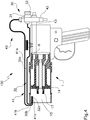
- the spray gun of the apparatus for flame spraying thermoplastic powders according to the invention has been indicated in its entirety with 100.
- a mixing device 1 is associated with the spray gun 100, the mixing device 1 being made up of a body 2 of tubular shape carrying, at a rear edge, a sealed head element 3, in which there are a first duct 4 for the feeding of the thermoplastic powders, transported by an inert gas, a second duct 5 for the feeding of a flow of compressed air and a third duct 6 for the feeding of liquefied petroleum gas or GPL, of the type for example of propane.
- GPL liquefied petroleum gas
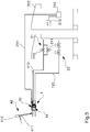
- the air is fed to the spray gun through an air compressor, of known type, not represented in figures, through a relative piping 110; the propane is fed to the spray gun through a suitable air cylinder 20, through a relative piping 120.
- the piping 110, 120 of the air compressor and of the cylinder of the propane are provided with suitable members 21, 22 for the adjustment of the outflow.
- the first duct 4 for the feeding of the powders is connected with a first discharge chamber 7 shaped by a tubular element 8 arranged according to the longitudinal axis of the body 2.
- the thermoplastic powders are fed to the duct 4 by a suitable load container 23, through a relative piping 19, with the interposition of a member 24, so called Venturi meter, configured to cause the controlled release of the same powders.
- a feed device 25 provided with a suitable mixing valve 26, as it is shown in figure 3 .
- the second duct 5 for the feeding of the mixture of air and/or nitrogen is connected with a second discharge chamber 9 shaped by a sleeve 10 externally coaxial to the tubular element 8.
- the second discharge chamber 9 is therefore shaped in annular shape between the inner surface of the sleeve 10 and the above mentioned tubular element 8.
- the sleeve 10 is tightly coupled, at a rear edge, with the head element 3 of the device, while at the front edge it shapes a front flange 11 which is associated, with sealing, with the inner surface of the body 2. Between such inner surface of the body 2 and the sleeve 10, a third discharge chamber 12 is shaped, which is in communication with the third duct 6 for the feeding of the propane gas.
- the tubular element 8 is constrained at its opposite ends respectively to the head element 3 and to the front flange 11, the front flange being provided with a suitable axial opening.
- the front flange 11 has, passing through, a first series of nozzles 13 and a second series of nozzles 14 configured to put in contact respectively the second discharge chamber 9 and the third discharge chamber 12 with a mixing chamber 15 shaped frontally to the same front flange 11.
- Such mixing chamber 15 extends inside an annular sleeve 16 frontally inserted on the body 2.
- the first series of nozzles 13 is of the type provided with a deflector member 17, as it is shown for example in figure 4 , such as to allow the adjustment of the width of the coating jet of the thermoplastic powder to be sprayed.
- the apparatus for spraying thermoplastic powders comprises a suitable flame ignition device 30. More precisely, such flame ignition device 30 is fixed to the gun 100 and comprises a spark strike device 31, 310, and a conductor element 32 associated with the mixing device 1. The conductor element 32 is connected with the spark strike device 31, 310 to ignite a spark inside or at the mixing chamber 15.
- the spark ignition device 31 is of the piezoelectric type, and is mounted on the spray gun.
- the conductor element 32 made up for example of an electrode (see figure 4 ) being rod-shaped, is connected at one end with the piezoelectric spark ignition device 31, and is provided with another free end at which a spark can be produced.
- the piezoelectric spark ignition device 31 is configured to produce a high-tension spark at the free end of the electrode 32, so as to start the flame.
- the electrode 32 is arranged in a way such as the spark is produced in the above mentioned mixing chamber 15, or close to it, to cause the ignition of the flame.
- the free end of the electrode 32 is placed inside the mixing chamber 15.
- the free end of the electrode 32 is located close to the above mentioned second series of nozzles 14, from which the liquefied petroleum gas comes out.
- the piezoelectric spark ignition device 31 is suitably provided with an activation means 33, for example a key, to enable the user to operate the piezoelectric spark ignition device 31 directly on the gun. More precisely, the operation key 33 is arranged so as to be easy reached by the user which uses the spray gun.
- the conductor element 32 comprises at least one first portion 32a extended longitudinally to the mixing device 1, and the spark ignition device 31 is arranged at a rear portion of the gun.
- the ignition device 30 has an electric spark ignition device 310, such as a transformer, connected with the electrode 32 through a suitable electric cable 311 ( figure 5 ).
- the spark ignition transformer 310 is arranged spaced from the spray gun, more precisely in a command board 312.
- the operation key for the above mentioned transformer 310 is arranged on the command board 312, so as to allow the remote starting of the flame.
- an electronic command device 313 is also provided, suitably arranged in the command board 312 and electrically connected with the transformer 310, as well as with the valve members 21, 22 for the adjustment of the discharge of air and gas, so as to control the activation thereof.
- the electronic command device 313 is configured to receive an activation signal from the ignition device 30 which confirms the correct ignition of the flame.
- the body of the electrode 32 has a first portion 32a, connected with the spark ignition device 31, 311 and longitudinally extended along the mixing device 1 on its whole length, a second portion 32b transversal to the first portion 32a and oriented towards the inside of the mixing chamber 15, and a third end portion 32c, substantially parallel to the first portion 32a and oriented in opposite direction, so as to result oriented towards the second series of nozzles 14, as previously mentioned.
- the electrode 32 is made up only of a first portion, longitudinal to the mixing device 1, and of a second end transversal portion, which crosses the tubular body 2 of the mixing device 1, so that its edge results to be at the second series of nozzles 14.
- the apparatus for spraying thermoplastic powders is preferably provided with a detection and monitor device 40 for the flame, configured to detect and monitor, preferably in continuous way, the presence of the flame coming out of the spray gun.
- the detection and monitor device 40 is as well suitable, in case of accidental extinguishment of the flame, to automatically operate the stop of the outflow of liquefied petroleum gas.
- such detection device 40 has temperature detection means 41, for example a thermocouple associated with the spray gun, and actuation means 42, for example a valve connected with the thermocouple 41, the valve 42 being configured to enable or interrupt the feeding of the liquefied petroleum gas.
- the thermocouple 41 and the valve 42 are suitably connected at a tubular element 43 associated with the spray gun and associated with the duct 6 for the feeding of the LPG, for the benefit of the compactness and manageability of the gun.
- the tubular element 43 is mounted at the rear portion of the gun 1, so as to cross the duct 6, engaging it through the valve 42.
- the valve 42 can be therefore operated between a closure position, in which it prevents the passage of LPG in the duct 6, and an open position, in which it allows the passage of LPG in the duct 6.
- the piezoelectric flame ignition device 31 is preferably mounted in fixed manner on the above mentioned tubular element 43, thus giving the gun a reduced volume.
- the thermocouple 41 has a rod-shaped body comprising a first portion 41a, external and longitudinal to the mixing device 1, a second transversal portion 41b arranged at the exit of the mixing chamber 15, and a third end portion 41c, arranged longitudinally to the mixing device 1 and oriented towards the inside of the mixing chamber 15.
- a thermocouple comprising a first portion external and longitudinal to the mixing device 1, and a second transversal end portion which passes through the wall of the tubular body 2 so as to have its end outside of the second series of nozzles 14 for the supply of gas.
- the detection and monitor device 40 of the flame is provided with optical detection means 410, for example a photocell, arranged in such a manner as to be able to visually detect the presence of the flame.
- optical detection means 410 for example a photocell, arranged in such a manner as to be able to visually detect the presence of the flame.
- the photocell 410 is oriented towards the exit of the mixing chamber 15 of the mixing device 1.
- the photocell 410 is provided with a cooling device 411, configured in this case to allow the inlet and the circulation of air in proximity of the photocell 410 in order to cool it.
- the detection device 40 is electrically connected with the electronic command device 313, and is configured to send it a suitable signal in case the flame is no more detected.
- the embodiments illustrated respectively in figures 4 and 5 do not represent a restriction of the combination of the embodiments of the ignition device 30 and of the detection and monitor device 40 for the flame.
- a gun provided with the piezoelectric spark ignition device 31 and with the photocell 410. It is possible as well to provide that the gun is connected with the electric spark ignition device 310 and equipped with the thermocouple 41.
- the spray gun is provided with a monoelectrode, which is configured to perform the ignition of the spark, in particular inside the mixing chamber 15, as well as to perform the detection and the monitoring of the flame, inside the mixing chamber 15. In such case, it is necessary that the free end of the monoelectrode is crossed by the flame to be monitored.
- the valve member 21 of control of the supply of air comprises a first valve 210, configured to allow the supply of low-pressure air, and a second valve 211, adapted to allow the supply of high-pressure air.
- the apparatus comprises as well a cooling device 50 for the gun 100, associated with the mixing device 1 of the same gun 100.
- the cooling device 50 comprises a hollow tubular body 51 adapted to be arranged, in use, about the mixing device 1, more precisely, around and coaxial to the body 2 of tubular shape and around the annular sleeve 16 inserted frontally to said body.
- the hollow tubular body 51 is adapted to shape, about the mixing chamber 15 of the gun 100, a cooling chamber 52 in which a cooling fluid is to be fed ( figure 7 ).
- the hollow tubular body 51 is suitably provided with at least one inlet opening 53 for the inlet of the above mentioned cooling fluid and of at least one outlet opening 54 for the outlet of the same cooling fluid.
- the inlet opening 53 and the outlet opening 54 are arranged on the longitudinal wall of the hollow tubular body 51.
- the cooling device 50 comprises feed means 55 for the cooling fluid, suitably connected with the inlet opening 53, and a cooling member 56, connected with feed means 55 of the fluid.
- the cooling member 56 is preferably tightly connected with the device 50 through the feed means 55, and is arranged close to the tubular body 51, to increase the efficiency and the manageability of the cooling device.
- cooling member 56 is of the pneumatic type, but it is possible to provide other kinds of cooling members.
- the cooling fluid is air, which is cooled by the cooling member 56.
- the cooling member 56 it is possible to provide any other type of cooling fluid according to the exigencies.
- the flame of the spray gun is ignited through the activation key 33 of the ignition device 31. It is obviously necessary that the valve member 22 for the supply of the liquefied petroleum gas is already open.
- thermocouple 41 When the flame is burning, its presence is detected by the thermocouple 41. The width of the flame is then adjusted by controlling the flow of compressed air fed through the second discharge chamber 9.
- the article to be coated it is possible to heat the article to be coated, according to its material, to a suitable working temperature, for example comprised between 90° and 200° C.
- the working temperature is essentially determined by the melting temperature of the used powders and can be then different form the one indicated for exemplary purpose.
- Such heating is suitably performed through the flame produced by the same spray gun of the apparatus, upon effect of the mixing of the propane gas and of the compressed air, or other inert gas such as for example nitrogen, fed to the front chamber 15 of the gun.
- the compressed air coming from the air compressor and the liquefied petroleum gas coming from the relative cylinder 20 are directed to the spray gun through the suitable valve members 21, 22 of control of the mixing which allow as well to adjust the exit pressure of the mixture.
- thermoplastic powders to be sprayed on the article are fed to the spray gun mixed with the cited transport inert gas, along with the air and the propane gas.
- the release of the powders is controlled by the cited Venturi meter member 24 or alternatively by the cited mixing valve 26.
- thermoplastic powders coming out of the discharge chamber 7 shaped by the sleeve 8 mix with the flow of air and/or nitrogen coming out of the coaxial discharge chamber 9. At this point, the thermoplastic powders pass through the above mentioned flame produced by the gun, and are heated inside the same flame.
- the apparatus according to the invention allows to control the melting of the thermoplastic powders inside the flame, enabling the user to adjust the width of the flame according to his needs through a suitable adjustment of the feed of air and LPG.
- the powders are then expelled from the spray gun and, inside the flame, projected onto the surface of the article to be coated.
- the desired melting of the powders is produced, or completed, at the contact of the surface of the article.
- thermocouple 41 An accidental extinguishment of the flame is automatically detected by the thermocouple 41. Such detection causes the closure of the valve 42, thus interrupting the feeding of the liquefied petroleum gas.
- the apparatus according to the invention achieves the scope of performing in an optimal way the spraying of thermoplastic powders, ensuring the preservation of the physical characteristics of the powders to be sprayed, as well as the safety of the users.
- Such a result is achieved by virtue of the inventive idea of providing a flame ignition device equipped with a spark ignition device 31, 310 and with a conductor element 32 associated with the mixing device 1.
- a flame ignition device equipped with a spark ignition device 31, 310 and with a conductor element 32 associated with the mixing device 1.
- Such device allows to avoid to start the flame through a lighter or a struck match being moved by hand towards to the outlet of the spray gun.
- a feature of the apparatus according to the present invention is also to provide a detection and monitoring device for the presence of the flame, advantageously adapted to allow the stop of the feeding of the liquefied petroleum gas.
- a characteristic of the present invention is as well to provide that, is case of extinguishment of the flame, the detection device sends a turn-off signal to the electronic control device, which subsequently operates the interruption of the feed of the liquefied petroleum gas. In such way, it is possible to prevent in a totally automatic way any possible dispersion of gas in the working environment, in favour of an even greater safety.
- a feature of the apparatus according to the invention is to be compact and easy to transport in the working area.
- the apparatus according to the invention can be mounted on a suitable wheel structure so as to be portable.
- Ad advantage of the apparatus according to the invention is due to the fact of allowing the spraying of the coating, creating different layers, by means of a single spray or by more subsequent sprays.
- a further advantage of the apparatus according to the invention is to work with a high spraying speed, so as to achieve a high productiveness.
- the apparatus according to the invention is of simple and steady construction and has a relatively reduced cost.
- the ignition of the flame occurs through the operation key placed in the command board 312.
- the operation of the activation key determines the simultaneous opening of the valve member 22 for the supply of the gas, the opening of the fist valve 210 for the supply of low pressure air, as well as the ignition of the spark to start the flame.
- the photocell 410 sends a suitable signal to the electronic command device 313. Also in case the valve member 21 for the supply of air is provided with the above mentioned first and second valve 210, 211, the electronic command device 313 will open the second valve 211 for the supply of the high-pressure air, to obtain a flame of greater volume.
- the photocell 410 automatically sends a suitable signal to the electronic command device 313, which in short time closes the valve member 22 for the supply of the liquefied petroleum gas.
- the overheating of the gun 100 is further prevented through the cooling device 50.
- the feeding means for the air 55 are operated along with the cooling member 56 which provides the cooling of the fed air.
- the so obtained cooled air is fed inside the cooling chamber 52 through the inlet opening 53.
- the cooled air is put in contact with the body 2 and the sleeve 16, inside which the flame is produced. Such contact allows a thermal exchange between the air and the body 2 and the sleeve 16, performing in known way the cooling of these latter.
Landscapes
- Chemical & Material Sciences (AREA)
- Engineering & Computer Science (AREA)
- Mechanical Engineering (AREA)
- Plasma & Fusion (AREA)
- Chemical Kinetics & Catalysis (AREA)
- Materials Engineering (AREA)
- Physics & Mathematics (AREA)
- Metallurgy (AREA)
- Organic Chemistry (AREA)
- Combustion & Propulsion (AREA)
- Analytical Chemistry (AREA)
- Nozzles (AREA)
- Application Of Or Painting With Fluid Materials (AREA)
Priority Applications (1)
| Application Number | Priority Date | Filing Date | Title |
|---|---|---|---|
| PL14815022T PL3068546T3 (pl) | 2013-11-12 | 2014-11-12 | Przyrząd do natryskiwania płomieniowego proszków termoplastycznych |
Applications Claiming Priority (2)
| Application Number | Priority Date | Filing Date | Title |
|---|---|---|---|
| IT000619A ITBO20130619A1 (it) | 2013-11-12 | 2013-11-12 | Metodo e apparecchiatura per la spruzzatura a fiamma di polveri termoplastiche |
| PCT/IB2014/065991 WO2015071840A1 (en) | 2013-11-12 | 2014-11-12 | Method and apparatus for flame spraying thermoplastic powders |
Publications (2)
| Publication Number | Publication Date |
|---|---|
| EP3068546A1 EP3068546A1 (en) | 2016-09-21 |
| EP3068546B1 true EP3068546B1 (en) | 2018-06-06 |
Family
ID=49683831
Family Applications (1)
| Application Number | Title | Priority Date | Filing Date |
|---|---|---|---|
| EP14815022.0A Active EP3068546B1 (en) | 2013-11-12 | 2014-11-12 | Method and apparatus for flame spraying thermoplastic powders |
Country Status (9)
| Country | Link |
|---|---|
| US (1) | US10190205B2 (pl) |
| EP (1) | EP3068546B1 (pl) |
| CN (1) | CN106163674B (pl) |
| ES (1) | ES2685846T3 (pl) |
| HU (1) | HUE039745T2 (pl) |
| IT (1) | ITBO20130619A1 (pl) |
| LT (1) | LT3068546T (pl) |
| PL (1) | PL3068546T3 (pl) |
| WO (1) | WO2015071840A1 (pl) |
Families Citing this family (7)
| Publication number | Priority date | Publication date | Assignee | Title |
|---|---|---|---|---|
| CN106583079B (zh) * | 2016-12-03 | 2019-10-11 | 天长市金陵电子有限责任公司 | 一种具有预热功能的喷塑枪 |
| IT201800007939A1 (it) * | 2018-08-07 | 2020-02-07 | Ibix Srl | Metodo e apparecchiatura per rivestire a fiamma con polveri termoplastiche elementi tubolari |
| IT201800009713A1 (it) * | 2018-10-23 | 2020-04-23 | Saipem Spa | Macchina e metodo di rivestimento a fiamma per rivestire giunzioni in campo di una tubazione |
| DE102019127302A1 (de) * | 2019-10-10 | 2021-04-15 | Herding Gmbh Filtertechnik | Verfahren zum Herstellen eines beschichteten Filterelements, Auftragsvorrichtung zum Beschichten eines Filterkörpers, sowie beschichtetes Filterelement |
| CN111871638B (zh) * | 2020-08-04 | 2021-08-13 | 丰宁满族自治县宏亭汽车部件有限公司 | 一种汽车喷漆用具有电动调节喷幅的喷枪及其使用方法 |
| CN115751309B (zh) * | 2022-12-01 | 2024-07-02 | 海顺新材料有限公司 | 一种氧化锌加热炉用喷火枪 |
| CN116060236B (zh) * | 2022-12-07 | 2023-10-20 | 江苏壹佰精工机械有限公司 | 一种粉末火焰熔射涂层喷涂系统 |
Family Cites Families (12)
| Publication number | Priority date | Publication date | Assignee | Title |
|---|---|---|---|---|
| GB553099A (en) | 1940-09-29 | 1943-05-07 | Fritz Gfeller | Improvements in processes and apparatus for spraying fusible and thermoplastic material |
| US5262206A (en) * | 1988-09-20 | 1993-11-16 | Plasma Technik Ag | Method for making an abradable material by thermal spraying |
| DE4443811A1 (de) * | 1994-12-09 | 1996-06-13 | Kuenzli Franz Ag | Universell anwendbarer Hochgeschwindigkeits-Flammspritzbrenner zum Verspritzen von draht-, stab- und/oder pulverförmigen Spritzzusatz-Werkstoffen |
| US5932293A (en) * | 1996-03-29 | 1999-08-03 | Metalspray U.S.A., Inc. | Thermal spray systems |
| AU1616500A (en) * | 1998-11-13 | 2000-06-05 | Thermoceramix, L.L.C. | System and method for applying a metal layer to a substrate |
| CN2494710Y (zh) * | 2001-08-31 | 2002-06-12 | 中国人民解放军第二炮兵工程学院 | 多功能超音速火焰喷涂喷枪 |
| CN1115203C (zh) * | 2001-08-31 | 2003-07-23 | 中国人民解放军第二炮兵工程学院 | 多功能超音速火焰喷涂方法及智能控制系统 |
| US20030209610A1 (en) * | 2001-12-14 | 2003-11-13 | Edward Miller | High velocity oxygen fuel (HVOF) method for spray coating non-melting polymers |
| US7261556B2 (en) * | 2004-05-12 | 2007-08-28 | Vladimir Belashchenko | Combustion apparatus for high velocity thermal spraying |
| FR2894599B1 (fr) * | 2005-12-13 | 2008-02-22 | Hmr Expert Sas Soc Par Actions | Methode et dispositif pour determiner et regler les parametres de projection thermique au cours d'un depot de revetement par projection thermique |
| DE102006047101B4 (de) * | 2006-09-28 | 2010-04-01 | Siemens Ag | Verfahren zum Einspeisen von Partikeln eines Schichtmaterials in einen Kaltgasspritzvorgang |
| CH702999A1 (de) | 2010-04-29 | 2011-10-31 | Amt Ag | Vorrichtung zur Beschichtung von Substraten mittels Hochgeschwindigkeitsflammspritzen. |
-
2013
- 2013-11-12 IT IT000619A patent/ITBO20130619A1/it unknown
-
2014
- 2014-11-12 US US15/036,166 patent/US10190205B2/en active Active
- 2014-11-12 CN CN201480070777.3A patent/CN106163674B/zh active Active
- 2014-11-12 LT LTEP14815022.0T patent/LT3068546T/lt unknown
- 2014-11-12 ES ES14815022.0T patent/ES2685846T3/es active Active
- 2014-11-12 WO PCT/IB2014/065991 patent/WO2015071840A1/en not_active Ceased
- 2014-11-12 EP EP14815022.0A patent/EP3068546B1/en active Active
- 2014-11-12 HU HUE14815022A patent/HUE039745T2/hu unknown
- 2014-11-12 PL PL14815022T patent/PL3068546T3/pl unknown
Non-Patent Citations (1)
| Title |
|---|
| None * |
Also Published As
| Publication number | Publication date |
|---|---|
| HUE039745T2 (hu) | 2019-02-28 |
| PL3068546T3 (pl) | 2018-12-31 |
| US10190205B2 (en) | 2019-01-29 |
| US20160281203A1 (en) | 2016-09-29 |
| ITBO20130619A1 (it) | 2015-05-13 |
| CN106163674B (zh) | 2019-06-11 |
| EP3068546A1 (en) | 2016-09-21 |
| ES2685846T3 (es) | 2018-10-11 |
| CN106163674A (zh) | 2016-11-23 |
| LT3068546T (lt) | 2018-11-12 |
| WO2015071840A1 (en) | 2015-05-21 |
Similar Documents
| Publication | Publication Date | Title |
|---|---|---|
| EP3068546B1 (en) | Method and apparatus for flame spraying thermoplastic powders | |
| EP0567569B1 (en) | Thermal spray method utilizing in-transit powder particle temperatures below their melting point | |
| RU2563462C2 (ru) | Многопламенная горелка с передачей пламени | |
| US2960275A (en) | Flame spray gun | |
| EP2022300A2 (en) | Plasma cutting device | |
| CN105605614A (zh) | 高能电子喷焰点火器 | |
| US20170089576A1 (en) | Torch ignition system and ignition assembly | |
| KR101723487B1 (ko) | 플라스틱 파우더 용사 코팅장치의 제어장치 및 이에 따르는 플라스틱 파우더 용사코팅용 코팅건 | |
| EP2599573B1 (en) | An oxycutting system and a pilot flame device for said system | |
| KR101729537B1 (ko) | 휴대용 부탄가스통에 장착되는 토치램프의 가스분출 장치 | |
| US2207765A (en) | Metal spray apparatus | |
| EP2864702B1 (en) | A heating torch | |
| KR200315509Y1 (ko) | 점화장치가 구비된 가스절단기 | |
| CN207523951U (zh) | 一种无人机搭载的喷气式喷火装置 | |
| CN116624870B (zh) | 一种自动点火喷火枪及焊接系统 | |
| WO2010111774A1 (en) | Method and device for concentrated heating of shrink sleeves | |
| RU141545U1 (ru) | Установка для газопламенного напыления наноструктурированного покрытия | |
| US2760543A (en) | Gas heated dimpling die | |
| US20140134348A1 (en) | Surface treatment device and method | |
| US1835845A (en) | Welding torch | |
| CN219453946U (zh) | 一种自动点火射吸式割炬 | |
| US8765050B1 (en) | Fluid injector to metal enclosure | |
| KR200476732Y1 (ko) | 가스토치 | |
| ITMI20110269A1 (it) | Apparecchiatura migliorata per la pulizia di torce di saldatura mediante l'uso del freddo, e relativo dispositivo erogatore di un flusso raffreddante | |
| KR0137810Y1 (ko) | 용접기용 불꽃 점화장치 |
Legal Events
| Date | Code | Title | Description |
|---|---|---|---|
| PUAI | Public reference made under article 153(3) epc to a published international application that has entered the european phase |
Free format text: ORIGINAL CODE: 0009012 |
|
| 17P | Request for examination filed |
Effective date: 20160610 |
|
| AK | Designated contracting states |
Kind code of ref document: A1 Designated state(s): AL AT BE BG CH CY CZ DE DK EE ES FI FR GB GR HR HU IE IS IT LI LT LU LV MC MK MT NL NO PL PT RO RS SE SI SK SM TR |
|
| AX | Request for extension of the european patent |
Extension state: BA ME |
|
| DAX | Request for extension of the european patent (deleted) | ||
| 17Q | First examination report despatched |
Effective date: 20170509 |
|
| GRAP | Despatch of communication of intention to grant a patent |
Free format text: ORIGINAL CODE: EPIDOSNIGR1 |
|
| INTG | Intention to grant announced |
Effective date: 20171218 |
|
| GRAS | Grant fee paid |
Free format text: ORIGINAL CODE: EPIDOSNIGR3 |
|
| GRAA | (expected) grant |
Free format text: ORIGINAL CODE: 0009210 |
|
| AK | Designated contracting states |
Kind code of ref document: B1 Designated state(s): AL AT BE BG CH CY CZ DE DK EE ES FI FR GB GR HR HU IE IS IT LI LT LU LV MC MK MT NL NO PL PT RO RS SE SI SK SM TR |
|
| REG | Reference to a national code |
Ref country code: GB Ref legal event code: FG4D |
|
| REG | Reference to a national code |
Ref country code: CH Ref legal event code: EP Ref country code: AT Ref legal event code: REF Ref document number: 1005463 Country of ref document: AT Kind code of ref document: T Effective date: 20180615 |
|
| REG | Reference to a national code |
Ref country code: IE Ref legal event code: FG4D |
|
| REG | Reference to a national code |
Ref country code: DE Ref legal event code: R096 Ref document number: 602014026768 Country of ref document: DE |
|
| REG | Reference to a national code |
Ref country code: CH Ref legal event code: NV Representative=s name: IP PARTNERS J. WENGER, CH |
|
| REG | Reference to a national code |
Ref country code: NL Ref legal event code: FP |
|
| REG | Reference to a national code |
Ref country code: ES Ref legal event code: FG2A Ref document number: 2685846 Country of ref document: ES Kind code of ref document: T3 Effective date: 20181011 |
|
| REG | Reference to a national code |
Ref country code: NO Ref legal event code: T2 Effective date: 20180606 |
|
| PG25 | Lapsed in a contracting state [announced via postgrant information from national office to epo] |
Ref country code: BG Free format text: LAPSE BECAUSE OF FAILURE TO SUBMIT A TRANSLATION OF THE DESCRIPTION OR TO PAY THE FEE WITHIN THE PRESCRIBED TIME-LIMIT Effective date: 20180906 Ref country code: SE Free format text: LAPSE BECAUSE OF FAILURE TO SUBMIT A TRANSLATION OF THE DESCRIPTION OR TO PAY THE FEE WITHIN THE PRESCRIBED TIME-LIMIT Effective date: 20180606 Ref country code: CY Free format text: LAPSE BECAUSE OF FAILURE TO SUBMIT A TRANSLATION OF THE DESCRIPTION OR TO PAY THE FEE WITHIN THE PRESCRIBED TIME-LIMIT Effective date: 20180606 |
|
| PG25 | Lapsed in a contracting state [announced via postgrant information from national office to epo] |
Ref country code: RS Free format text: LAPSE BECAUSE OF FAILURE TO SUBMIT A TRANSLATION OF THE DESCRIPTION OR TO PAY THE FEE WITHIN THE PRESCRIBED TIME-LIMIT Effective date: 20180606 Ref country code: HR Free format text: LAPSE BECAUSE OF FAILURE TO SUBMIT A TRANSLATION OF THE DESCRIPTION OR TO PAY THE FEE WITHIN THE PRESCRIBED TIME-LIMIT Effective date: 20180606 Ref country code: LV Free format text: LAPSE BECAUSE OF FAILURE TO SUBMIT A TRANSLATION OF THE DESCRIPTION OR TO PAY THE FEE WITHIN THE PRESCRIBED TIME-LIMIT Effective date: 20180606 |
|
| PG25 | Lapsed in a contracting state [announced via postgrant information from national office to epo] |
Ref country code: SK Free format text: LAPSE BECAUSE OF FAILURE TO SUBMIT A TRANSLATION OF THE DESCRIPTION OR TO PAY THE FEE WITHIN THE PRESCRIBED TIME-LIMIT Effective date: 20180606 Ref country code: RO Free format text: LAPSE BECAUSE OF FAILURE TO SUBMIT A TRANSLATION OF THE DESCRIPTION OR TO PAY THE FEE WITHIN THE PRESCRIBED TIME-LIMIT Effective date: 20180606 Ref country code: CZ Free format text: LAPSE BECAUSE OF FAILURE TO SUBMIT A TRANSLATION OF THE DESCRIPTION OR TO PAY THE FEE WITHIN THE PRESCRIBED TIME-LIMIT Effective date: 20180606 Ref country code: EE Free format text: LAPSE BECAUSE OF FAILURE TO SUBMIT A TRANSLATION OF THE DESCRIPTION OR TO PAY THE FEE WITHIN THE PRESCRIBED TIME-LIMIT Effective date: 20180606 Ref country code: IS Free format text: LAPSE BECAUSE OF FAILURE TO SUBMIT A TRANSLATION OF THE DESCRIPTION OR TO PAY THE FEE WITHIN THE PRESCRIBED TIME-LIMIT Effective date: 20181006 |
|
| PG25 | Lapsed in a contracting state [announced via postgrant information from national office to epo] |
Ref country code: SM Free format text: LAPSE BECAUSE OF FAILURE TO SUBMIT A TRANSLATION OF THE DESCRIPTION OR TO PAY THE FEE WITHIN THE PRESCRIBED TIME-LIMIT Effective date: 20180606 |
|
| REG | Reference to a national code |
Ref country code: HU Ref legal event code: AG4A Ref document number: E039745 Country of ref document: HU |
|
| REG | Reference to a national code |
Ref country code: DE Ref legal event code: R097 Ref document number: 602014026768 Country of ref document: DE |
|
| REG | Reference to a national code |
Ref country code: GR Ref legal event code: EP Ref document number: 20180402524 Country of ref document: GR Effective date: 20190225 |
|
| PLBE | No opposition filed within time limit |
Free format text: ORIGINAL CODE: 0009261 |
|
| STAA | Information on the status of an ep patent application or granted ep patent |
Free format text: STATUS: NO OPPOSITION FILED WITHIN TIME LIMIT |
|
| 26N | No opposition filed |
Effective date: 20190307 |
|
| PG25 | Lapsed in a contracting state [announced via postgrant information from national office to epo] |
Ref country code: DK Free format text: LAPSE BECAUSE OF FAILURE TO SUBMIT A TRANSLATION OF THE DESCRIPTION OR TO PAY THE FEE WITHIN THE PRESCRIBED TIME-LIMIT Effective date: 20180606 Ref country code: SI Free format text: LAPSE BECAUSE OF FAILURE TO SUBMIT A TRANSLATION OF THE DESCRIPTION OR TO PAY THE FEE WITHIN THE PRESCRIBED TIME-LIMIT Effective date: 20180606 |
|
| PG25 | Lapsed in a contracting state [announced via postgrant information from national office to epo] |
Ref country code: MC Free format text: LAPSE BECAUSE OF FAILURE TO SUBMIT A TRANSLATION OF THE DESCRIPTION OR TO PAY THE FEE WITHIN THE PRESCRIBED TIME-LIMIT Effective date: 20180606 |
|
| PG25 | Lapsed in a contracting state [announced via postgrant information from national office to epo] |
Ref country code: AL Free format text: LAPSE BECAUSE OF FAILURE TO SUBMIT A TRANSLATION OF THE DESCRIPTION OR TO PAY THE FEE WITHIN THE PRESCRIBED TIME-LIMIT Effective date: 20180606 |
|
| PG25 | Lapsed in a contracting state [announced via postgrant information from national office to epo] |
Ref country code: MT Free format text: LAPSE BECAUSE OF NON-PAYMENT OF DUE FEES Effective date: 20181112 |
|
| PG25 | Lapsed in a contracting state [announced via postgrant information from national office to epo] |
Ref country code: PT Free format text: LAPSE BECAUSE OF FAILURE TO SUBMIT A TRANSLATION OF THE DESCRIPTION OR TO PAY THE FEE WITHIN THE PRESCRIBED TIME-LIMIT Effective date: 20180606 |
|
| PG25 | Lapsed in a contracting state [announced via postgrant information from national office to epo] |
Ref country code: MK Free format text: LAPSE BECAUSE OF NON-PAYMENT OF DUE FEES Effective date: 20180606 |
|
| PG25 | Lapsed in a contracting state [announced via postgrant information from national office to epo] |
Ref country code: GR Free format text: LAPSE BECAUSE OF NON-PAYMENT OF DUE FEES Effective date: 20200609 |
|
| REG | Reference to a national code |
Ref country code: AT Ref legal event code: UEP Ref document number: 1005463 Country of ref document: AT Kind code of ref document: T Effective date: 20180606 |
|
| P01 | Opt-out of the competence of the unified patent court (upc) registered |
Effective date: 20230403 |
|
| PGFP | Annual fee paid to national office [announced via postgrant information from national office to epo] |
Ref country code: HU Payment date: 20241028 Year of fee payment: 11 |
|
| PGFP | Annual fee paid to national office [announced via postgrant information from national office to epo] |
Ref country code: LT Payment date: 20241028 Year of fee payment: 11 |
|
| PGFP | Annual fee paid to national office [announced via postgrant information from national office to epo] |
Ref country code: NO Payment date: 20241202 Year of fee payment: 11 |
|
| PGFP | Annual fee paid to national office [announced via postgrant information from national office to epo] |
Ref country code: BE Payment date: 20241129 Year of fee payment: 11 Ref country code: NL Payment date: 20241129 Year of fee payment: 11 Ref country code: FI Payment date: 20241111 Year of fee payment: 11 Ref country code: PL Payment date: 20241028 Year of fee payment: 11 Ref country code: LU Payment date: 20241129 Year of fee payment: 11 |
|
| PGFP | Annual fee paid to national office [announced via postgrant information from national office to epo] |
Ref country code: GB Payment date: 20241218 Year of fee payment: 11 |
|
| PGFP | Annual fee paid to national office [announced via postgrant information from national office to epo] |
Ref country code: FR Payment date: 20241129 Year of fee payment: 11 |
|
| PGFP | Annual fee paid to national office [announced via postgrant information from national office to epo] |
Ref country code: AT Payment date: 20241129 Year of fee payment: 11 |
|
| PGFP | Annual fee paid to national office [announced via postgrant information from national office to epo] |
Ref country code: IE Payment date: 20241128 Year of fee payment: 11 |
|
| PGFP | Annual fee paid to national office [announced via postgrant information from national office to epo] |
Ref country code: IT Payment date: 20241129 Year of fee payment: 11 |
|
| PGFP | Annual fee paid to national office [announced via postgrant information from national office to epo] |
Ref country code: CH Payment date: 20241206 Year of fee payment: 11 |
|
| PGFP | Annual fee paid to national office [announced via postgrant information from national office to epo] |
Ref country code: TR Payment date: 20241030 Year of fee payment: 11 |
|
| PGFP | Annual fee paid to national office [announced via postgrant information from national office to epo] |
Ref country code: DE Payment date: 20241231 Year of fee payment: 11 |
|
| PGFP | Annual fee paid to national office [announced via postgrant information from national office to epo] |
Ref country code: ES Payment date: 20241230 Year of fee payment: 11 |
|
| REG | Reference to a national code |
Ref country code: CH Ref legal event code: U11 Free format text: ST27 STATUS EVENT CODE: U-0-0-U10-U11 (AS PROVIDED BY THE NATIONAL OFFICE) Effective date: 20251202 |