EP3067498B1 - Device for opening and/or closing a wing - Google Patents
Device for opening and/or closing a wing Download PDFInfo
- Publication number
- EP3067498B1 EP3067498B1 EP16154405.1A EP16154405A EP3067498B1 EP 3067498 B1 EP3067498 B1 EP 3067498B1 EP 16154405 A EP16154405 A EP 16154405A EP 3067498 B1 EP3067498 B1 EP 3067498B1
- Authority
- EP
- European Patent Office
- Prior art keywords
- leaf
- sash
- side component
- wall
- covering element
- Prior art date
- Legal status (The legal status is an assumption and is not a legal conclusion. Google has not performed a legal analysis and makes no representation as to the accuracy of the status listed.)
- Active
Links
Images


Classifications
-
- E—FIXED CONSTRUCTIONS
- E05—LOCKS; KEYS; WINDOW OR DOOR FITTINGS; SAFES
- E05F—DEVICES FOR MOVING WINGS INTO OPEN OR CLOSED POSITION; CHECKS FOR WINGS; WING FITTINGS NOT OTHERWISE PROVIDED FOR, CONCERNED WITH THE FUNCTIONING OF THE WING
- E05F1/00—Closers or openers for wings, not otherwise provided for in this subclass
-
- E—FIXED CONSTRUCTIONS
- E05—LOCKS; KEYS; WINDOW OR DOOR FITTINGS; SAFES
- E05F—DEVICES FOR MOVING WINGS INTO OPEN OR CLOSED POSITION; CHECKS FOR WINGS; WING FITTINGS NOT OTHERWISE PROVIDED FOR, CONCERNED WITH THE FUNCTIONING OF THE WING
- E05F15/00—Power-operated mechanisms for wings
- E05F15/60—Power-operated mechanisms for wings using electrical actuators
- E05F15/603—Power-operated mechanisms for wings using electrical actuators using rotary electromotors
- E05F15/611—Power-operated mechanisms for wings using electrical actuators using rotary electromotors for swinging wings
-
- E—FIXED CONSTRUCTIONS
- E05—LOCKS; KEYS; WINDOW OR DOOR FITTINGS; SAFES
- E05F—DEVICES FOR MOVING WINGS INTO OPEN OR CLOSED POSITION; CHECKS FOR WINGS; WING FITTINGS NOT OTHERWISE PROVIDED FOR, CONCERNED WITH THE FUNCTIONING OF THE WING
- E05F1/00—Closers or openers for wings, not otherwise provided for in this subclass
- E05F1/08—Closers or openers for wings, not otherwise provided for in this subclass spring-actuated, e.g. for horizontally sliding wings
- E05F1/10—Closers or openers for wings, not otherwise provided for in this subclass spring-actuated, e.g. for horizontally sliding wings for swinging wings, e.g. counterbalance
-
- E—FIXED CONSTRUCTIONS
- E05—LOCKS; KEYS; WINDOW OR DOOR FITTINGS; SAFES
- E05F—DEVICES FOR MOVING WINGS INTO OPEN OR CLOSED POSITION; CHECKS FOR WINGS; WING FITTINGS NOT OTHERWISE PROVIDED FOR, CONCERNED WITH THE FUNCTIONING OF THE WING
- E05F3/00—Closers or openers with braking devices, e.g. checks; Construction of pneumatic or liquid braking devices
- E05F3/22—Additional arrangements for closers, e.g. for holding the wing in opened or other position
- E05F3/227—Additional arrangements for closers, e.g. for holding the wing in opened or other position mounted at the top of wings, e.g. details related to closer housings, covers, end caps or rails therefor
-
- E—FIXED CONSTRUCTIONS
- E05—LOCKS; KEYS; WINDOW OR DOOR FITTINGS; SAFES
- E05F—DEVICES FOR MOVING WINGS INTO OPEN OR CLOSED POSITION; CHECKS FOR WINGS; WING FITTINGS NOT OTHERWISE PROVIDED FOR, CONCERNED WITH THE FUNCTIONING OF THE WING
- E05F3/00—Closers or openers with braking devices, e.g. checks; Construction of pneumatic or liquid braking devices
- E05F3/22—Additional arrangements for closers, e.g. for holding the wing in opened or other position
- E05F2003/228—Arrangements where the end of the closer arm is sliding in a track
-
- E—FIXED CONSTRUCTIONS
- E05—LOCKS; KEYS; WINDOW OR DOOR FITTINGS; SAFES
- E05F—DEVICES FOR MOVING WINGS INTO OPEN OR CLOSED POSITION; CHECKS FOR WINGS; WING FITTINGS NOT OTHERWISE PROVIDED FOR, CONCERNED WITH THE FUNCTIONING OF THE WING
- E05F15/00—Power-operated mechanisms for wings
- E05F15/60—Power-operated mechanisms for wings using electrical actuators
- E05F15/603—Power-operated mechanisms for wings using electrical actuators using rotary electromotors
- E05F15/611—Power-operated mechanisms for wings using electrical actuators using rotary electromotors for swinging wings
- E05F15/63—Power-operated mechanisms for wings using electrical actuators using rotary electromotors for swinging wings operated by swinging arms
- E05F2015/631—Power-operated mechanisms for wings using electrical actuators using rotary electromotors for swinging wings operated by swinging arms the end of the arm sliding in a track; Slider arms therefor
-
- E—FIXED CONSTRUCTIONS
- E05—LOCKS; KEYS; WINDOW OR DOOR FITTINGS; SAFES
- E05Y—INDEXING SCHEME RELATING TO HINGES OR OTHER SUSPENSION DEVICES FOR DOORS, WINDOWS OR WINGS AND DEVICES FOR MOVING WINGS INTO OPEN OR CLOSED POSITION, CHECKS FOR WINGS AND WING FITTINGS NOT OTHERWISE PROVIDED FOR, CONCERNED WITH THE FUNCTIONING OF THE WING
- E05Y2201/00—Constructional elements; Accessories therefore
- E05Y2201/10—Covers; Housings
- E05Y2201/11—Covers
Definitions
- the present invention relates to a device for the self-opening and / or closing of a rotary axis rotatable wing, in particular a door closer or a door drive, with a trained for attachment to the wing wing-side component, designed for attachment to a frame, a wall or the like wall side Component and a movable lever assembly, via which the wing-side component and the wall-side component are coupled together such that they are apart by a lever movement or towards each other, so as to open or close the wing.
- Such devices are used on doors, gates, windows, skylights and the like to open the respective door or window wing power-operated and / or close.
- Examples of generic devices are door closers, door drives and window drives.
- Door closers are known, for example in the form of overhead door closers and serve to automatically close a door or gate wing after its opening and subsequent release.
- Door and window drives are equipped with a drive system and therefore able to open and close a rotatable wing motor.
- That component which provides the opening and / or closing force ie the closing body of a door closer or the drive unit of a door drive, attached to the upper edge of the door leaf and one or more articulated levers with a above the door leaf arranged sliding or Coupled guide rail. It may also be that the Sliding or guide rail on the door leaf and the closing body or the drive unit is attached to the frame, the wall or the ceiling.
- the lever assembly between the wall-side component and the wing-side component is arranged and recognizable as a separate assembly. When the door is closed so for a viewer, the three modules "wall-side component", “wing-side component” and “lever assembly” are visible and disturb the room image.
- DE19717959A1 discloses a device according to the preamble of claim 1. It is an object of the invention to provide a device for automatically opening and / or closing a rotatable about a rotation axis door, in which the above-mentioned disadvantages are eliminated. The object is achieved by a device having the features of claim 1.
- a cover element is movably mounted on the wall-side component or on the wing-side component, which in a first position at least partially covers a visible side of the lever arrangement and / or the wing and is moved out of the movement path of the lever arrangement and the wing in a second position.
- the lever assembly can be covered with the wing closed so that it is no longer recognizable as a separate component.
- Door closer, door drives and the like can thus be better integrated into the room image.
- the cover can the Lever arrangement and if necessary even overlap the wing forward, since it can be moved away to open the wing. Due to the cover, it is not necessary to produce the lever assembly in different color variants and to keep in stock.
- the cover element is mounted pivotably about a pivot axis on the wall-side component or on the wing-side component.
- Another embodiment of the invention provides that the cover is slidably mounted on the wall-side component or on the wing-side component, in particular wherein the displacement track extends transversely to an opening direction of the wing.
- the cover can cover or release the visible side of the lever assembly.
- the cover element In the first position, the cover element preferably covers at least substantially completely an air gap formed between the wing-side component and the wall-side component. Covering this air gap by a fixed cover separates, as this would block a lever movement. Due to the mobility of the cover, however, it is possible to bridge the air gap and thus to create a particularly smooth transition between the wing-side component and the wall-side component.
- An embodiment of the invention provides that the cover is mounted on the wall-side component and defined in the first position, at least on a front side a flush transition to a housing of the wing-side component or that the cover is mounted on the wing-side component and in the first position defined at least on a front side a flush transition to a housing of the wall-side component.
- the front of the cover is meant that side which faces away from the door in the mounted state of the door closer or the door drive.
- the cover may be designed hood-like, so that it covers that component to which it is movably mounted to several sides.
- a hood-like cover member may have a curved outer side to give the device a particularly appealing design.
- At least one front side of the cover element is adapted in terms of its surface texture and color to a housing of the wing-side component and / or the wall-side component.
- a door closer or door drive for a viewer with closed wing acts as a single component.
- Such a device fits much better in the room image as a device with three separate and clearly recognizable as such individual components.
- the pivot axis of a pivotably mounted cover member extends in the assembled state of the device at least substantially horizontally.
- the cover can thus be swung up or down from the path of movement of the lever assembly and / or the wing when the wing is opened laterally.
- the cover member has an urging surface which is arranged and formed such that upon opening of the wing, a portion of the lever assembly or the wing presses against the loading surface and thus moves the cover member in the direction of the second position.
- the cover is thus automatically pivoted when opening the wing or shifted without the need for a special drive mechanism is provided.
- the production cost is particularly low in this embodiment. In principle, however, it is also possible to move the cover motor - for example, sensor-controlled.
- the covering element has a flat cover section with a front side facing away from the wing in the mounted state of the door device and an opposite rear side, wherein the loading surface is formed on the rear side of the flat cover section.
- the loading surface may be formed as a sliding surface, d. H. due to the shape, the choice of materials and the surface texture for a slipping of the acting component be particularly suitable.
- the loading surface may be inclined and / or curved relative to an opening direction of the wing.
- the corresponding mating surface of the lever arrangement or of the wing may extend obliquely and / or curved with respect to an opening direction of the wing.
- a further embodiment of the invention provides that the wall-side component or the wing-side component comprises an elongated hollow profile element which is closed at least one open end by an end piece, wherein on the end piece a pivot pin or a pivot pin receptacle is provided for pivotally mounting the cover.
- both open end faces of the elongated hollow profile element are closed by end pieces with pivot pins or pivot pin receptacles.
- pivot pin and the associated pivot pin receptacles can be designed such that a clipping or snapping the cover into the associated end piece is possible.
- the assembly of the cover is particularly simple in this embodiment.
- a further embodiment of the invention provides that the pivot pin or the pivot pin receptacle is arranged asymmetrically with respect to a mirror plane of the end piece and / or that the end piece has a plurality of pivot pins or pivot pin receptacles. This allows the storage of the cover in different positions, so as to accommodate, for example, different types of door closers or door drives.
- An inventive device may comprise a damping element which opposes the movement of the cover member a resistance.
- the damping element may be formed as a rotational damper and interact directly with a pivot pin or a pivot pin receptacle of the cover. This allows a particularly simple construction.
- a linear damper could be used as a damping element.
- a further embodiment of the invention provides that the cover element is acted upon by a prestressed spring in the direction of the first position. In this way it is ensured that the cover reliably moves into the covering position as soon as the wing is closed. That is, it is prevented that the cover member unintentionally remains in the aside moved position. In certain applications, it may be sufficient to provide for moving the cover member toward the first position solely by gravity. In this case, no separate spring is necessary.
- the wing-side component is designed as a housing for accommodating a closing mechanism or a drive of the device and the wall-side component as a slide rail for receiving a slider of the lever arrangement, or vice versa.
- the cover element can partially or completely cover the slide rail, the lever arrangement and the housing.
- the cover can be mounted on two opposite end faces of the slide, in particular articulated, be, so that it surrounds the slide rail in a manner of brackets. This allows a particularly simple structure and also ensures lateral coverage of the slide rail.
- the cover element may comprise a central wall section for covering the visible side of the lever arrangement and / or the wing and two lateral wall sections extending transversely to the central wall section, on the mutually facing inner sides of which respective pivot pins or pivot pin receptacles are arranged.
- a cover which is composed essentially of three flat wall sections, is particularly simple and inexpensive to produce.
- the cover element can at least partially cover both a visible side of the wing-side component and a visible side of the wall-side component.
- the cover member may pivot about a transverse to the axis of rotation of the wing pivot axis on the wall-side component or on the be mounted wing-side component. This is contrary to a mounting on the upper edge of a laterally rotating wing.
- the invention also relates to a cover member adapted for moveable bearing on a wall-side or wing-side component of a device as described above.
- a cover member adapted for moveable bearing on a wall-side or wing-side component of a device as described above.
- Existing door closers, door drives or the like can be retrofitted with such a cover to allow better integration into the room image.
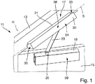
- Partially illustrated door 11 comprises a wall-fixed frame 13 and a relative to the frame 13 about a vertical axis of rotation R rotatable door leaf 15.
- an inventive door closer 17 is mounted, which is fixed to the door leaf 15 closer body 19 and attached to the frame 13
- Sliding rail 21 includes.
- a lever assembly 23 - here in the form of a single-arm single lever - the closer body 19 and the slide 21 are coupled together.
- the lever assembly 23 is coupled in the embodiment shown at one end to a projecting out of the closer body 19 closer shaft 25 drivingly effective and at the other end hinged to a run in the slide rail 21 slider 22 (FIG. Fig. 2-4 ) connected.
- a non-visible locking mechanism is housed, which pivots, for example by means of spring force on the closer shaft 25, the lever assembly 23 so that the door 15 automatically closes after opening and subsequent release.
- the closer body 19 could also be attached to the frame 13 and the slide rail 21 on the door leaf 15.
- a cover member 30 is pivotally mounted about a horizontal pivot axis S.
- the pivot axis S thus extends at right angles to the axis of rotation R and parallel to a longitudinal extent of the slide rail 21.
- the cover element 30 comprises a central wall portion 31 and two transverse to this extending lateral wall portions 33.
- the cover 30 is hinged to the two opposite end faces of the slide rail 21. It can be pivoted between a lowered position and a raised position, as will be explained in more detail below.
- the cover member 30 is adapted in terms of its surface texture and color to the closer body 19 to further enhance the impression of a uniform component.
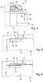
- the lever assembly 23 presses against the back 40 of the central wall portion 31, whereby this is slowly pivoted upwards ( Fig. 3 ). After the door leaf 15 has reached an opening angle of about 30 °, the lower edge 41 of the central wall portion 31 is as in Fig. 4 recognizable on the lever assembly 23. Upon further opening of the door leaf 15, the lever arrangement 23 slides along the lower edge 41 of the central wall section 31. The cover 30 is in this case completely out of the Movement path of the lever assembly 23 and the door leaf 15 swung out.
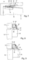
- the rear side 40 'of the central wall section 31' has a curved contour 42 in order to allow the lever arrangement 23 to slide more easily onto the lower edge 41 of the central wall section 31 '.
- the slide rail 21 is according to 10 and 11 formed as an elongated hollow profile element which is closed at the two open end faces 45 by respective end pieces 47.
- Each of the end pieces 47 has a pivot pin receptacle 49 in the form of a recess such as a blind hole or a through hole.
- the pivot pin receptacles 49 of the end pieces 47 serve to receive respective pivot pins 50 which are arranged on the mutually facing inner sides of the lateral wall sections 33 of the cover element 30.
- the pivot pin receptacles 49 are each as in FIG Fig. 10 recognizable with respect to a mirror plane E of the tail 47 arranged asymmetrically.
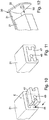
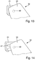
- the end pieces 47 as in Fig. 13 illustrated with zargennah arranged pivot pin receptacles 49 or as in Fig. 14 shown with zargenfern arranged pivot pin receptacles 49 are inserted into the slide rail 21, different arrangements of the cover 30 relative to the slide rail 21.
- cover 30 and end pieces 47 are mounted in a different manner to a door closer 17, so that Accordingly, two different variants of door closers 17 can be equipped with the same cover 30.
- a plurality of spaced-apart pivot pin receptacles 49 may be provided in an end piece 47.
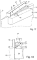
- FIGS. 15 and 16 show an alternative designed cover member 30 'including an associated end piece 47'.
- a pivot pin receptacle 53 is provided on the mutually facing inner sides of the lateral wall portions 33.
- This pivot pin receptacle 53 engages the profiled first shaft end 55 of a rotary damper 57, which is designed for insertion into the end piece 47 '.
- the opposite second shaft end 59 of the rotary damper 57 which is also profiled, is received in a receptacle 60 at the bottom of the end piece 47 '.
- a spring such as B. be a leg spring integrated into the pivot bearing.
- the cover 30, 30 ' not only as in the illustrated embodiments, the slide rail 21 and the lever assembly 23 cover, but if necessary, the closer body 19 and / or the upper edge of the door 15. That is, depending on the size and shape of the Cover member 30, 30 'different designs of the door closer 17 possible.
- the cover element 30 is not pivotable, but displaceably mounted on the slide rail 21.
- corresponding linear guides are provided on the opposite end sections of the slide rail, which are arranged in Fig. 17-21 are not shown separately.
- the linear guides are preferably designed as sliding guides.
- the displaceable cover element 30 is formed exclusively by a central wall section 31", that is to say there are no lateral wall sections. In the assembled state of the door closer 17 ', the movement path of the sliding movement is vertical.
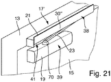
- a run-on slope 70 is provided, which is arranged here at the end of the lever arrangement 23, but in principle could also be arranged at another location of the door closer 17 '
- Wing 15 is the ramp 30 as in Fig. 18 shown at the lower edge 41 of the central wall portion 31 "on and the cover 30" is held by gravity and optionally additionally by spring force in the lower end position.
- an existing door closer 17 can be retrofitted with a cover in a simple and fast manner.
- the invention makes it possible to integrate door closers, door drives and the like in a particularly visually appealing manner in a room image.
Description
Die vorliegende Erfindung betrifft eine Einrichtung zum selbsttägigen Öffnen und/oder Schließen eines um eine Drehachse drehbaren Flügels, insbesondere einen Türschließer oder einen Türantrieb, mit einer zur Befestigung am Flügel ausgebildeten flügelseitigen Komponente, einer zur Befestigung an einer Zarge, einer Wand oder dergleichen ausgebildeten wandseitigen Komponente und einer beweglichen Hebelanordnung, über welche die flügelseitige Komponente und die wandseitige Komponente derart miteinander gekoppelt sind, dass sie durch eine Hebelbewegung auseinander oder aufeinander zu bewegbar sind, um so den Flügel zu öffnen oder zu schließen.The present invention relates to a device for the self-opening and / or closing of a rotary axis rotatable wing, in particular a door closer or a door drive, with a trained for attachment to the wing wing-side component, designed for attachment to a frame, a wall or the like wall side Component and a movable lever assembly, via which the wing-side component and the wall-side component are coupled together such that they are apart by a lever movement or towards each other, so as to open or close the wing.
Derartige Einrichtungen werden an Türen, Toren, Fenstern, Oberlichten und dergleichen dazu eingesetzt, den betreffenden Tür- oder Fensterflügel kraftbetätigt zu öffnen und/oder zu schließen. Beispiele für gattungsgemäße Einrichtungen sind Türschließer, Türantriebe und Fensterantriebe.Such devices are used on doors, gates, windows, skylights and the like to open the respective door or window wing power-operated and / or close. Examples of generic devices are door closers, door drives and window drives.
Türschließer sind beispielsweise in Form von Obentürschließern bekannt und dienen dazu, einen Tür- oder Torflügel nach dessen Öffnen und anschließendem Loslassen selbsttätig wieder zu schließen. Tür- und Fensterantriebe sind mit einem Antriebssystem ausgestattet und daher in der Lage, einen drehbaren Flügel motorisch zu öffnen und zu schließen.Door closers are known, for example in the form of overhead door closers and serve to automatically close a door or gate wing after its opening and subsequent release. Door and window drives are equipped with a drive system and therefore able to open and close a rotatable wing motor.
Häufig ist diejenige Komponente, welche die Öffnungs- und/oder Schließkraft bereitstellt, also der Schließerkörper eines Türschließers bzw. die Antriebseinheit eines Türantriebs, am oberen Rand des Türblatts befestigt und über einen oder mehrere gelenkig verbundene Hebel mit einer oberhalb des Türblatts angeordneten Gleit- oder Führungsschiene gekoppelt. Es kann jedoch auch sein, dass die Gleit- oder Führungsschiene am Türblatt und der Schließerkörper bzw. die Antriebseinheit an der Zarge, der Wand oder der Decke befestigt ist. In jedem Fall ist die Hebelanordnung zwischen der wandseitigen Komponente und der flügelseitigen Komponente angeordnet und als separate Baugruppe erkennbar.
Bei geschlossener Tür sind also für einen Betrachter die drei Baugruppen "wandseitige Komponente", "flügelseitige Komponente" und "Hebelanordnung" offen sichtbar und stören das Raumbild. Um ein ansprechenderes Erscheinungsbild zu ermöglichen, werden Türschließer und Türantriebe häufig in verschiedenen Farbvarianten angeboten. Dies bedeutet jedoch, dass alle drei genannten Komponenten in unterschiedlichen Farben lackiert und auf Lager gelegt werden müssen. Dies ist mit einem beträchtlichen Aufwand verbunden.
Die Lösung der Aufgabe erfolgt durch eine Einrichtung mit den Merkmalen des Anspruchs 1.
Erfindungsgemäß ist an der wandseitigen Komponente oder an der flügelseitigen Komponente ein Abdeckelement beweglich gelagert, welches in einer ersten Stellung eine Sichtseite der Hebelanordnung und/oder des Flügels zumindest bereichsweise überdeckt und in einer zweiten Stellung aus der Bewegungsbahn der Hebelanordnung und des Flügels herausbewegt ist. Mit einem solchen Abdeckelement kann die Hebelanordnung bei geschlossenem Flügel derart abgedeckt werden, dass sie nicht mehr als separate Komponente erkennbar ist. Türschließer, Türantriebe und dergleichen können somit besser in das Raumbild integriert werden. Anders als bei herkömmlichen Systemen kann das Abdeckelement die Hebelanordnung und bei Bedarf sogar den Flügel nach vorn übergreifen, da es zum Öffnen des Flügels wegbewegt werden kann. Aufgrund des Abdeckelements ist es nicht notwendig, die Hebelanordnung in verschiedenen Farbvarianten herzustellen und auf Lager zu halten.Often, that component which provides the opening and / or closing force, ie the closing body of a door closer or the drive unit of a door drive, attached to the upper edge of the door leaf and one or more articulated levers with a above the door leaf arranged sliding or Coupled guide rail. It may also be that the Sliding or guide rail on the door leaf and the closing body or the drive unit is attached to the frame, the wall or the ceiling. In any case, the lever assembly between the wall-side component and the wing-side component is arranged and recognizable as a separate assembly.
When the door is closed so for a viewer, the three modules "wall-side component", "wing-side component" and "lever assembly" are visible and disturb the room image. To enable a more attractive appearance, door closers and door operators are often offered in different color variants. However, this means that all three components mentioned must be painted in different colors and put in stock. This is associated with a considerable effort.
The object is achieved by a device having the features of claim 1.
According to the invention, a cover element is movably mounted on the wall-side component or on the wing-side component, which in a first position at least partially covers a visible side of the lever arrangement and / or the wing and is moved out of the movement path of the lever arrangement and the wing in a second position. With such a cover, the lever assembly can be covered with the wing closed so that it is no longer recognizable as a separate component. Door closer, door drives and the like can thus be better integrated into the room image. Unlike conventional systems, the cover can the Lever arrangement and if necessary even overlap the wing forward, since it can be moved away to open the wing. Due to the cover, it is not necessary to produce the lever assembly in different color variants and to keep in stock.
Weiterbildungen der Erfindung sind in den abhängigen Ansprüchen, der Beschreibung sowie der beigefügten Zeichnung angegeben.Further developments of the invention are specified in the dependent claims, the description and the accompanying drawings.
Gemäß einer Ausführungsform der Erfindung ist das Abdeckelement um eine Schwenkachse verschwenkbar an der wandseitigen Komponente oder an der flügelseitigen Komponente gelagert. Eine andere Ausführungsform der Erfindung sieht vor, dass das Abdeckelement verschiebbar an der wandseitigen Komponente oder an der flügelseitigen Komponente gelagert ist, insbesondere wobei die Verschiebebahn quer zu einer Öffnungsrichtung des Flügels verläuft. Je nach Schwenkstellung bzw. Verschiebestellung kann das Abdeckelement die Sichtseite der Hebelanordnung abdecken oder freigeben.According to one embodiment of the invention, the cover element is mounted pivotably about a pivot axis on the wall-side component or on the wing-side component. Another embodiment of the invention provides that the cover is slidably mounted on the wall-side component or on the wing-side component, in particular wherein the displacement track extends transversely to an opening direction of the wing. Depending on the pivot position or displacement position, the cover can cover or release the visible side of the lever assembly.
Vorzugsweise deckt das Abdeckelement in der ersten Stellung einen zwischen der flügelseitigen Komponente und der wandseitigen Komponente ausgebildeten Luftspalt zumindest im Wesentlichen vollständig ab. Ein Abdecken dieses Luftspalts durch ein feststehendes Abdeckelement scheidet aus, da hierdurch eine Hebelbewegung blockiert wäre. Aufgrund der Beweglichkeit des Abdeckelements ist es hingegen möglich, den Luftspalt zu überbrücken und somit einen besonders glatten Übergang zwischen der flügelseitigen Komponente und der wandseitigen Komponente zu schaffen.In the first position, the cover element preferably covers at least substantially completely an air gap formed between the wing-side component and the wall-side component. Covering this air gap by a fixed cover separates, as this would block a lever movement. Due to the mobility of the cover, however, it is possible to bridge the air gap and thus to create a particularly smooth transition between the wing-side component and the wall-side component.
Eine Ausgestaltung der Erfindung sieht vor, dass das Abdeckelement an der wandseitigen Komponente gelagert ist und in der ersten Stellung zumindest an einer Vorderseite einen bündigen Übergang zu einem Gehäuse der flügelseitigen Komponente definiert oder dass das Abdeckelement an der flügelseitigen Komponente gelagert ist und in der ersten Stellung zumindest an einer Vorderseite einen bündigen Übergang zu einem Gehäuse der wandseitigen Komponente definiert. Mit der Vorderseite des Abdeckelements ist diejenige Seite gemeint, die im montierten Zustand des Türschließers oder der Türantriebs von der Tür weg weist. Durch einen bündigen Übergang zwischen dem Abdeckelement und einem angrenzenden Gehäuse wie zum Beispiel dem Gehäuse eines Schließerkörpers oder einer Antriebseinheit kann ein besonders ansprechendes Erscheinungsbild des Türschließers oder Türantriebs geschaffen werden.An embodiment of the invention provides that the cover is mounted on the wall-side component and defined in the first position, at least on a front side a flush transition to a housing of the wing-side component or that the cover is mounted on the wing-side component and in the first position defined at least on a front side a flush transition to a housing of the wall-side component. With the front of the cover is meant that side which faces away from the door in the mounted state of the door closer or the door drive. By a flush transition between the cover and an adjacent housing such as the housing of a shutter body or a drive unit, a particularly appealing appearance of the door closer or door drive can be created.
Das Abdeckelement kann haubenartig gestaltet sein, so dass es diejenige Komponente, an der es beweglich gelagert ist, zu mehreren Seiten hin überdeckt. Ein solches haubenartiges Abdeckelement kann eine gewölbte Außenseite aufweisen, um der Einrichtung ein besonders ansprechendes Design zu verleihen.The cover may be designed hood-like, so that it covers that component to which it is movably mounted to several sides. Such a hood-like cover member may have a curved outer side to give the device a particularly appealing design.
Gemäß einer Ausführungsform der Erfindung ist zumindest eine Vorderseite des Abdeckelements hinsichtlich seiner Oberflächenbeschaffenheit und Farbgebung an ein Gehäuse der flügelseitigen Komponente und/oder der wandseitigen Komponente angepasst. Auf diese Weise kann erzielt werden, dass ein Türschließer oder Türantrieb für einen Betrachter bei geschlossenem Flügel wie eine einzelne Komponente wirkt. Eine derartige Einrichtung fügt sich wesentlich besser in das Raumbild als eine Einrichtung mit drei separaten und deutlich als solche erkennbaren Einzelkomponenten.According to one embodiment of the invention, at least one front side of the cover element is adapted in terms of its surface texture and color to a housing of the wing-side component and / or the wall-side component. In this way, it can be achieved that a door closer or door drive for a viewer with closed wing acts as a single component. Such a device fits much better in the room image as a device with three separate and clearly recognizable as such individual components.
Vorzugsweise verläuft die Schwenkachse eines verschwenkbar gelagerten Abdeckelements im montierten Zustand der Einrichtung zumindest im Wesentlichen horizontal. Das Abdeckelement kann somit nach oben oder nach unten aus der Bewegungsbahn der Hebelanordnung und/oder des Flügels herausgeschwenkt werden, wenn der Flügel seitlich geöffnet wird.Preferably, the pivot axis of a pivotably mounted cover member extends in the assembled state of the device at least substantially horizontally. The cover can thus be swung up or down from the path of movement of the lever assembly and / or the wing when the wing is opened laterally.
Es ist bevorzugt, dass das Abdeckelement eine Beaufschlagungsfläche aufweist, die derart angeordnet und ausgebildet ist, dass bei einem Öffnen des Flügels ein Abschnitt der Hebelanordnung oder des Flügels gegen die Beaufschlagungsfläche drückt und so das Abdeckelement in Richtung der zweiten Stellung bewegt. Das Abdeckelement wird somit beim Öffnen des Flügels automatisch verschwenkt oder verschoben, ohne dass hierfür ein spezieller Antriebsmechanismus vorzusehen ist. Der Herstellungsaufwand ist bei dieser Ausgestaltung besonders gering. Grundsätzlich ist es jedoch auch möglich, das Abdeckelement motorisch zu bewegen - beispielsweise sensorgesteuert.It is preferred that the cover member has an urging surface which is arranged and formed such that upon opening of the wing, a portion of the lever assembly or the wing presses against the loading surface and thus moves the cover member in the direction of the second position. The cover is thus automatically pivoted when opening the wing or shifted without the need for a special drive mechanism is provided. The production cost is particularly low in this embodiment. In principle, however, it is also possible to move the cover motor - for example, sensor-controlled.
Es kann vorgesehen sein, dass das Abdeckelement einen flächigen Deckabschnitt mit einer im montierten Zustand der Türeinrichtung vom Flügel weg weisenden Vorderseite und einer entgegengesetzten Rückseite aufweist, wobei die Beaufschlagungsfläche an der Rückseite des flächigen Deckabschnitts ausgebildet ist. Dies ermöglicht eine besonders einfache Konstruktion, da die Hebelanordnung bei einem Öffnen des Flügels das abdeckende Bauteil gewissermaßen direkt von hinten wegdrückt.It can be provided that the covering element has a flat cover section with a front side facing away from the wing in the mounted state of the door device and an opposite rear side, wherein the loading surface is formed on the rear side of the flat cover section. This allows a particularly simple construction, since the lever arrangement presses the covering component to a certain extent directly from behind when the wing is opened.
Die Beaufschlagungsfläche kann als Gleitfläche ausgebildet sein, d. h. aufgrund der Formgebung, der Materialauswahl sowie der Oberflächenbeschaffenheit für ein Entlanggleiten des beaufschlagenden Bauteils in besonderer Weise geeignet sein. Speziell kann die Beaufschlagungsfläche bezüglich einer Öffnungsrichtung des Flügels schräg und/oder gekrümmt verlaufen. Alternativ oder zusätzlich kann die entsprechende Gegenfläche der Hebelanordnung oder des Flügels bezüglich einer Öffnungsrichtung des Flügels schräg und/oder gekrümmt verlaufen.The loading surface may be formed as a sliding surface, d. H. due to the shape, the choice of materials and the surface texture for a slipping of the acting component be particularly suitable. Specifically, the loading surface may be inclined and / or curved relative to an opening direction of the wing. Alternatively or additionally, the corresponding mating surface of the lever arrangement or of the wing may extend obliquely and / or curved with respect to an opening direction of the wing.
Eine weitere Ausführungsform der Erfindung sieht vor, dass die wandseitige Komponente oder die flügelseitige Komponente ein längliches Hohlprofilelement umfasst, welches an wenigstens einer offenen Stirnseite durch ein Endstück verschlossen ist, wobei an dem Endstück ein Schwenkzapfen oder eine Schwenkzapfenaufnahme zur schwenkbaren Lagerung des Abdeckelements vorgesehen ist. Vorzugsweise sind beide offenen Stirnseiten des länglichen Hohlprofilelements durch Endstücke mit Schwenkzapfen oder Schwenkzapfenaufnahmen verschlossen. Das Vorsehen eines Endstücks oder zweier Endstücke ermöglicht eine besonders einfache Lagerung des Abdeckelements an der betreffenden Komponente. Außerdem sind viele gängige Türschließer und Türantriebe mit länglichen Hohlprofilelementen in Form von Gleit- oder Führungsschienen ausgestattet.A further embodiment of the invention provides that the wall-side component or the wing-side component comprises an elongated hollow profile element which is closed at least one open end by an end piece, wherein on the end piece a pivot pin or a pivot pin receptacle is provided for pivotally mounting the cover. Preferably, both open end faces of the elongated hollow profile element are closed by end pieces with pivot pins or pivot pin receptacles. The provision of an end piece or two end pieces allows a particularly simple storage of the cover on the relevant component. In addition, many common door closers and door operators are equipped with elongated hollow profile elements in the form of sliding or guide rails.
Durch Bereitstellung passender Endstücke sowie eines zugehörigen Abdeckelements können derartige Systeme leicht mit einer schwenkbaren Abdeckung nachgerüstet werden. Die Schwenkzapfen und die zugehörigen Schwenkzapfenaufnahmen können derart gestaltet sein, dass ein Einklipsen oder Einschnappen des Abdeckelements in das zugehörige Endstück möglich ist. Die Montage des Abdeckelements ist bei dieser Ausgestaltung besonders einfach.By providing suitable end pieces and an associated cover member such systems can be easily retrofitted with a hinged cover. The pivot pin and the associated pivot pin receptacles can be designed such that a clipping or snapping the cover into the associated end piece is possible. The assembly of the cover is particularly simple in this embodiment.
Eine weitere Ausführungsform der Erfindung sieht vor, dass der Schwenkzapfen oder die Schwenkzapfenaufnahme bezüglich einer Spiegelebene des Endstücks asymmetrisch angeordnet ist und/oder dass das Endstück mehrere Schwenkzapfen oder Schwenkzapfenaufnahmen aufweist. Dies ermöglicht die Lagerung des Abdeckelements in verschiedenen Positionen, um so zum Beispiel unterschiedlichen Typen von Türschließern oder Türantrieben Rechnung zu tragen.A further embodiment of the invention provides that the pivot pin or the pivot pin receptacle is arranged asymmetrically with respect to a mirror plane of the end piece and / or that the end piece has a plurality of pivot pins or pivot pin receptacles. This allows the storage of the cover in different positions, so as to accommodate, for example, different types of door closers or door drives.
Eine erfindungsgemäße Einrichtung kann ein Dämpfungselement umfassen, welches der Bewegung des Abdeckelements einen Widerstand entgegensetzt. Dadurch kann ein sanftes Bewegen des Abdeckelements gewährleistet werden. Insbesondere kann das Dämpfungselement als Rotationsdämpfer ausgebildet sein und direkt mit einem Schwenkzapfen oder einer Schwenkzapfenaufnahme des Abdeckelements zusammenwirken. Dies ermöglicht eine besonders einfache Konstruktion. Grundsätzlich könnte auch ein Lineardämpfer als Dämpfungselement eingesetzt werden.An inventive device may comprise a damping element which opposes the movement of the cover member a resistance. As a result, a smooth movement of the cover can be ensured. In particular, the damping element may be formed as a rotational damper and interact directly with a pivot pin or a pivot pin receptacle of the cover. This allows a particularly simple construction. In principle, a linear damper could be used as a damping element.
Eine weitere Ausführungsform der Erfindung sieht vor, dass das Abdeckelement durch eine vorgespannte Feder in Richtung der ersten Stellung beaufschlagt ist. Auf diese Weise ist sichergestellt, dass sich das Abdeckelement zuverlässig in die abdeckende Stellung bewegt, sobald der Flügel geschlossen wird. Das heißt es wird verhindert, dass das Abdeckelement unbeabsichtigter Weise in der beiseite bewegten Stellung verbleibt. Bei bestimmten Anwendungen kann es ausreichend sein, ein Bewegen des Abdeckelements in Richtung der ersten Stellung ausschließlich aufgrund der Schwerkraft vorzusehen. In diesem Fall ist keine separate Feder notwendig.A further embodiment of the invention provides that the cover element is acted upon by a prestressed spring in the direction of the first position. In this way it is ensured that the cover reliably moves into the covering position as soon as the wing is closed. That is, it is prevented that the cover member unintentionally remains in the aside moved position. In certain applications, it may be sufficient to provide for moving the cover member toward the first position solely by gravity. In this case, no separate spring is necessary.
Gemäß einer speziellen Ausgestaltung der Erfindung ist die flügelseitige Komponente als ein Gehäuse zur Unterbringung eines Schließmechanismus oder eines Antriebs der Einrichtung und die wandseitige Komponente als eine Gleitschiene zur Aufnahme eines Gleitstücks der Hebelanordnung ausgebildet, oder umgekehrt. Das Abdeckelement kann bei einer derartigen Ausgestaltung die Gleitschiene, die Hebelanordnung und das Gehäuse teilweise oder vollständig abdecken.According to a particular embodiment of the invention, the wing-side component is designed as a housing for accommodating a closing mechanism or a drive of the device and the wall-side component as a slide rail for receiving a slider of the lever arrangement, or vice versa. In such a configuration, the cover element can partially or completely cover the slide rail, the lever arrangement and the housing.
Das Abdeckelement kann an zwei entgegengesetzten Stirnseiten der Gleitschiene gelagert, insbesondere angelenkt, sein, so dass es die Gleitschiene gewissermaßen klammerartig umgreift. Dies ermöglicht einen besonders einfachen Aufbau und sorgt zudem für eine seitliche Abdeckung der Gleitschiene.The cover can be mounted on two opposite end faces of the slide, in particular articulated, be, so that it surrounds the slide rail in a manner of brackets. This allows a particularly simple structure and also ensures lateral coverage of the slide rail.
Das Abdeckelement kann einen zentralen Wandabschnitt zum Abdecken der Sichtseite der Hebelanordnung und/oder des Flügels und zwei sich quer zu dem zentralen Wandabschnitt erstreckende seitliche Wandabschnitte umfassen, an deren einander zugewandten Innenseiten jeweilige Schwenkzapfen oder Schwenkzapfenaufnahmen angeordnet sind. Ein derartiges Abdeckelement, das sich im Wesentlichen aus drei flächigen Wandabschnitten zusammensetzt, ist besonders einfach und kostengünstig herstellbar.The cover element may comprise a central wall section for covering the visible side of the lever arrangement and / or the wing and two lateral wall sections extending transversely to the central wall section, on the mutually facing inner sides of which respective pivot pins or pivot pin receptacles are arranged. Such a cover, which is composed essentially of three flat wall sections, is particularly simple and inexpensive to produce.
Das Abdeckelement kann in der ersten Stellung sowohl eine Sichtseite der flügelseitigen Komponente als auch eine Sichtseite der wandseitigen Komponente zumindest bereichsweise überdecken. Insbesondere kann vorgesehen sein, dass ein - vorzugsweise haubenartiges - Abdeckelement sowohl die flügelseitige Komponente als auch die wandseitige Komponente im Wesentlichen vollständig überdeckt. Dies sorgt für ein besonders ansprechendes Erscheinungsbild des zugehörigen Türschließers, Türantriebs oder dergleichen.In the first position, the cover element can at least partially cover both a visible side of the wing-side component and a visible side of the wall-side component. In particular, it may be provided that a cover element-preferably a hood-substantially completely covers both the wing-side component and the wall-side component. This ensures a particularly appealing appearance of the associated door closer, door drive or the like.
Das Abdeckelement kann um eine quer zu der Drehachse des Flügels verlaufende Schwenkachse verschwenkbar an der wandseitigen Komponente oder an der flügelseitigen Komponente gelagert sein. Dies kommt einer Montage am oberen Rand eines seitlich drehenden Flügels entgegen.The cover member may pivot about a transverse to the axis of rotation of the wing pivot axis on the wall-side component or on the be mounted wing-side component. This is contrary to a mounting on the upper edge of a laterally rotating wing.
Die Erfindung betrifft auch ein Abdeckelement, das zum beweglichen Lagern an einer wandseitigen oder flügelseitigen Komponente einer Einrichtung wie vorstehend beschrieben ausgebildet ist. Bestehende Türschließer, Türantriebe oder dergleichen können mit einem solchen Abdeckelement nachgerüstet werden, um eine bessere Integration in das Raumbild zu ermöglichen.The invention also relates to a cover member adapted for moveable bearing on a wall-side or wing-side component of a device as described above. Existing door closers, door drives or the like can be retrofitted with such a cover to allow better integration into the room image.
Die Erfindung wird nachfolgend beispielhaft unter Bezugnahme auf die Zeichnung beschrieben.
- Fig. 1
- ist eine perspektivische Teildarstellung einer Tür, an der ein Türschließer gemäß einer ersten Ausführungsform der Erfindung montiert ist.
- Fig. 2
- ist eine seitliche Schnittdarstellung der in
Fig. 1 gezeigten Anordnung, wobei sich ein Flügel der Tür in geschlossenem Zustand befindet. - Fig. 3
- zeigt die Tür gemäß
Fig. 2 mit teilweise geöffnetem Flügel. - Fig. 4
- zeigt die Tür gemäß
Fig. 2 mit gegenüberFig. 3 weiter geöffnetem Flügel. - Fig. 5
- zeigt die Anordnung gemäß
Fig. 2 in perspektivischer Ansicht. - Fig. 6
- zeigt die Anordnung gemäß
Fig. 3 in perspektivischer Ansicht. - Fig. 7
- zeigt die Anordnung gemäß
Fig. 4 in perspektivischer Ansicht. - Fig. 8
- ist eine seitliche Schnittansicht einer Tür, an der ein Türschließer gemäß einer zweiten Ausführungsform der Erfindung montiert ist, wobei sich ein Flügel der Tür in geschlossenem Zustand befindet.
- Fig. 9
- zeigt die in
Fig. 8 dargestellte Anordnung mit teilweise geöffnetem Flügel. - Fig. 10
- zeigt eine Gleitschiene eines erfindungsgemäßen Türschließers sowie ein Endstück zum Einsetzen in eine offene Stirnseite der Gleitschiene.
- Fig. 11
- zeigt die Gleitschiene gemäß
Fig. 10 mit eingesetztem Endstück. - Fig. 12
- zeigt die Anordnung gemäß
Fig. 11 einschließlich eines an der Gleitschiene zu lagernden Abdeckelements. - Fig. 13
- zeigt eine Gleitschiene mit daran gelagertem Abdeckelement gemäß einer ersten Montage-Variante.
- Fig. 14
- zeigt eine Gleitschiene mit daran gelagertem Abdeckelement gemäß einer alternativen zweiten Montage-Variante.
- Fig. 15
- zeigt ein gegenüber
Fig. 10 alternativ gestaltetes Endstück, an welchem über ein Dämpfungselement ein Abdeckelement zu lagern ist. - Fig. 16
- zeigt die Anordnung gemäß
Fig. 15 in teilweise zusammengesetztem Zustand. - Fig. 17
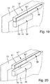
- ist eine perspektivische Teildarstellung einer Tür, an der ein Türschließer gemäß einer dritten Ausführungsform der Erfindung montiert ist.
- Fig. 18
- ist eine seitliche Schnittdarstellung der in
Fig. 17 gezeigten Anordnung, wobei sich ein Flügel der Tür in geschlossenem Zustand befindet. - Fig. 19
- zeigt die Anordnung gemäß
Fig. 18 in perspektivischer Ansicht. - Fig. 20
- zeigt die Anordnung gemäß
Fig. 19 mit teilweise geöffnetem Flügel. - Fig. 21
- zeigt die Anordnung gemäß
Fig. 19 mit gegenüberFig. 20 weiter geöffnetem Flügel.
- Fig. 1
- is a partial perspective view of a door on which a door closer according to a first embodiment of the invention is mounted.
- Fig. 2
- is a side sectional view of the in
Fig. 1 shown arrangement, wherein a wing of the door is in the closed state. - Fig. 3
- shows the door according to
Fig. 2 with partially opened wing. - Fig. 4
- shows the door according to
Fig. 2 with oppositeFig. 3 wide open wing. - Fig. 5
- shows the arrangement according to
Fig. 2 in perspective view. - Fig. 6
- shows the arrangement according to
Fig. 3 in perspective view. - Fig. 7
- shows the arrangement according to
Fig. 4 in perspective view. - Fig. 8
- is a side sectional view of a door on which a door closer according to a second embodiment of the invention is mounted, wherein a door of the door is in the closed state.
- Fig. 9
- shows the in
Fig. 8 illustrated arrangement with partially opened wing. - Fig. 10
- shows a slide rail of a door closer according to the invention and an end piece for insertion into an open end side of the slide rail.
- Fig. 11
- shows the slide according to
Fig. 10 with inserted end piece. - Fig. 12
- shows the arrangement according to
Fig. 11 including a cover member to be stored on the slide rail. - Fig. 13
- shows a slide rail with it mounted cover according to a first mounting variant.
- Fig. 14
- shows a slide with it mounted cover according to an alternative second mounting variant.
- Fig. 15
- shows one opposite
Fig. 10 alternatively designed tail, on which a damping element is to store a cover. - Fig. 16
- shows the arrangement according to
Fig. 15 in partially assembled condition. - Fig. 17
- is a partial perspective view of a door on which a door closer according to a third embodiment of the invention is mounted.
- Fig. 18
- is a side sectional view of the in
Fig. 17 shown arrangement, wherein a wing of the door is in the closed state. - Fig. 19
- shows the arrangement according to
Fig. 18 in perspective view. - Fig. 20
- shows the arrangement according to
Fig. 19 with partially opened wing. - Fig. 21
- shows the arrangement according to
Fig. 19 with oppositeFig. 20 wide open wing.
Die in
An der Gleitschiene 21 ist ein Abdeckelement 30 um eine horizontale Schwenkachse S verschwenkbar gelagert. Die Schwenkachse S verläuft bei dem gezeigten Ausführungsbeispiel also rechtwinklig zu der Rotationsachse R und parallel zu einer Längserstreckung der Gleitschiene 21. Das Abdeckelement 30 umfasst einen zentralen Wandabschnitt 31 sowie zwei sich quer zu diesem erstreckende seitliche Wandabschnitte 33. Über die seitlichen Wandabschnitte 33 ist das Abdeckelement 30 an den beiden entgegengesetzten Stirnseiten der Gleitschiene 21 angelenkt. Es kann zwischen einer herabgeschwenkten Stellung und einer emporgeschwenkten Stellung verschwenkt werden, wie nachfolgend noch genauer ausgeführt wird.On the
Wenn der Türflügel 15 geschlossen ist und sich das Abdeckelement 30 wie in
Beim Öffnen des Türflügels 15 drückt die Hebelanordnung 23 gegen die Rückseite 40 des zentralen Wandabschnitts 31, wodurch dieser langsam nach oben geschwenkt wird (
Bei der in
In den
Die Schwenkzapfenaufnahmen 49 sind jeweils wie in
Bei den dargestellten Ausführungsbeispielen verschwenkt das Abdeckelement 30, 30' aufgrund der Schwerkraft in die untere Stellung, sobald die Hebelanordnung 23 die Unterkante 41 des zentralen Wandabschnitts 31,31' nicht mehr stützt. Um diese Rückstellkraft zu verstärken oder bei anderer Einbaulage ebenfalls ein selbsttätiges Verschwenken des Abdeckelements 30, 30' zu ermöglichen, kann eine Feder wie z. B. eine Schenkelfeder in das Schwenklager integriert sein.In the illustrated embodiments, the
Das Abdeckelement 30, 30' kann nicht nur wie bei den dargestellten Ausführungsbeispielen die Gleitschiene 21 sowie die Hebelanordnung 23 überdecken, sondern bei Bedarf auch den Schließerkörper 19 und/oder den oberen Rand des Türflügels 15. Das heißt es sind je nach Größe und Formgebung des Abdeckelements 30, 30' verschiedene Gestaltungen des Türschließers 17 möglich.The
Bei dem in
Um das Abdeckelement 30" bei einem Öffnen des Flügels 15 nach oben zu drücken, ist eine Auflaufschräge 70 vorgesehen, die hier am Ende der Hebelanordnung 23 angeordnet ist, im Prinzip aber auch an einer anderen Stelle des Türschließers 17' angeordnet sein könnte. Bei geschlossenem Flügel 15 liegt die Auflaufschräge 70 wie in
Abgesehen von einer verschiebbaren anstelle einer verschwenkbaren Lagerung des Abdeckelements 30" ist der in
Der Einfachheit halber wurde die vorstehende Beschreibung der Ausführungsbeispiele auf einen Türschließer 17, 17' beschränkt. Es versteht sich jedoch, dass das bewegliche Abdeckelement 30, 30', 30" ebenso in einen Türantrieb oder in einen Fensterantrieb integriert sein könnte, wobei anstelle eines Schließerkörpers 19 eine entsprechende Antriebseinheit vorgesehen wäre. Sämtliche die Ausführungsbeispiele betreffenden Offenbarungen gelten sinngemäß auch für einen Tür- oder Fensterantrieb.For the sake of simplicity, the above description of the embodiments has been limited to a door closer 17, 17 '. However, it is understood that the
Durch Bereitstellen einer Anordnung aus Abdeckelement 30, 30' und jeweils zwei zugehörigen Endstücken 47, 47' kann in einfacher und schneller Weise ein bestehender Türschließer 17 mit einer Abdeckung nachgerüstet werden.By providing an arrangement of
Die Erfindung ermöglicht es, Türschließer, Türantriebe und dergleichen in optisch besonders ansprechender Weise in ein Raumbild zu integrieren.The invention makes it possible to integrate door closers, door drives and the like in a particularly visually appealing manner in a room image.
- 1111
- Türdoor
- 1313
- Zargeframe
- 1515
- Türflügeldoor
- 17, 17'17, 17 '
- Türschließerdoor closers
- 1919
- Schließerkörpercloser body
- 2121
- Gleitschieneslide
- 2222
- Gleitstückslide
- 2323
- Hebelanordnunglever assembly
- 2525
- Schließerwellecloser shaft
- 30, 30', 30"30, 30 ', 30 "
- Abdeckelementcover
- 31, 31', 31"31, 31 ', 31 "
- zentraler Wandabschnittcentral wall section
- 33,33'33.33 '
- seitlicher Wandabschnittlateral wall section
- 3535
- Vorderseite der GleitschieneFront of the slide rail
- 3838
- Vorderseite des AbdeckelementsFront of the cover
- 3939
- Vorderseite des SchließerkörpersFront of the closer body
- 40, 40', 40"40, 40 ', 40 "
- Rückseite des zentralen WandabschnittsBack side of the central wall section
- 4141
- Unterkantelower edge
- 4242
- Konturcontour
- 4545
- offene Stirnseiteopen front
- 47, 47'47, 47 '
- Endstücktail
- 4949
- SchwenkzapfenaufnahmePivot pin receiver
- 5050
- Schwenkzapfenpivot pin
- 5353
- SchwenkzapfenaufnahmePivot pin receiver
- 5555
- erstes Wellenendefirst wave end
- 5757
- Rotationsdämpferrotary damper
- 5959
- zweites Wellenendesecond shaft end
- 6060
- Aufnahmeadmission
- 7070
- Auflaufschrägeapproach ramp
- RR
- Drehachseaxis of rotation
- SS
- Schwenkachseswivel axis
- Ee
- Spiegelebenemirror plane
Claims (20)
- Device (17, 17') for the automatic opening and/or closing of a leaf/sash (15) which can be rotated about an axis of rotation (R), in particular a door closer or door drive, having a leaf/sash-side component (19) designed for fastening to the leaf/sash (15), a wall-side component (21) designed for fastening to a frame (13), a wall or the like, and a movable lever arrangement (23) via which the leaf/sash-side component (19) and the wall-side component (21) are coupled to one another in such a way that they can be moved apart from one another or towards one another by a lever movement in order thus to open or to close the leaf/sash (15),
characterized in that
the wall-side component (21) or the leaf/sash-side component (19) has movably mounted thereon a covering element (30, 30', 30") which, in a first position, covers a visible side of the lever arrangement (23) and/or of the leaf/sash (15) at least in certain regions and, in a second position, is moved out of the movement path of the lever arrangement (23) and of the leaf/sash (15). - Device according to Claim 1,
characterized in that,
in the first position, the covering element (30, 30', 30") at least substantially completely covers an air gap formed between the leaf/sash-side component (19) and the wall-side component (21). - Device according to Claim 1 or 2,
characterized in that
the covering element (30, 30', 30") is mounted on the wall-side component (21) and defines, in the first position, at least on a front side (38), a flush transition to a housing of the leaf/sash-side component (19), or in that the covering element (30, 30', 30") is mounted on the leaf/sash-side component (19) and defines, in the first position, at least on a front side (38), a flush transition to a housing of the wall-side component (21). - Device according to one of the preceding claims,
characterized in that
the covering element (30, 30') is designed in the manner of a cap and preferably has a curved outer side. - Device according to one of the preceding claims,
characterized in that
at least a front side (38) of the covering element (30, 30', 30") is adapted in terms of its surface nature and colour to a housing of the leaf/sash-side component (19) and/or of the wall-side component (21) . - Device according to one of the preceding claims,
characterized in that
the covering element (30, 30', 30") has a loading surface (40, 40', 40") which is arranged and designed in such a way that, during an opening of the leaf/sash (15), a portion of the lever arrangement (23) or of the leaf/sash (15) presses against the loading surface (40, 40') and thus moves the covering element (30, 30', 30") in the direction of the second position. - Device according to Claim 6,
characterized in that
the covering element (30, 30', 30") has a flat cover portion (31, 31', 31") with a front side (38), which is directed away from the leaf/sash (15) in the mounted state of the device (17, 17'), and with an opposite rear side (40, 40', 40"), wherein the loading surface is formed on the rear side (40, 40', 40") of the flat cover portion (31, 31', 31"). - Device according to Claim 6 or 7,
characterized in that
the loading surface (40, 40', 40") is formed as a sliding surface and, preferably, extends in an oblique and/or curved manner with respect to an opening direction of the leaf/sash (15). - Device according to one of the preceding claims,
characterized by
a damping element (57) which offers a resistance to the movement of the covering element (30'). - Device according to one of the preceding claims,
characterized in that
the covering element (30, 30', 30") is loaded in the direction of the first position by a prestressed spring. - Device according to one of the preceding claims,
characterized in that
the leaf/sash-side component (19) is designed as a housing for accommodating a closing mechanism or a drive of the device (17, 17') and the wall-side component (21) is designed as a sliding rail for receiving a sliding piece (22) of the lever arrangement (23), or vice versa. - Device according to Claim 11,
characterized in that
the covering element (30, 30') is mounted, in particular articulated, on two opposite end sides (45) of the sliding rail (21). - Device according to one of the preceding claims,
characterized in that,
in the first position, the covering element covers both a visible side of the leaf/sash-side component (19) and a visible side of the wall-side component (21), at least in certain regions. - Device according to one of the preceding claims,
characterized in that
the covering element (30, 30') is mounted on the wall-side component (21) or on the leaf/sash-side component (19) so as to be pivotable about a pivot axis (S). - Device according to Claim 14,
characterized in that,
in the mounted state of the device (17, 17'), the pivot axis (S) extends at least substantially horizontally. - Device according to Claim 14 or 15,
characterized in that
the wall-side component (21) or the leaf/sash-side component (19) comprises an elongate hollow profile element which is closed at at least one open end side (45) by an end piece (47, 47'), wherein a pivot plug (55) or a pivot plug receptacle (49) for pivotably mounting the covering element (30, 30') is provided on the end piece (47, 47'). - Device according to Claim 16,
characterized in that
the pivot plug (55) or the pivot plug receptacle (49) is arranged asymmetrically with respect to a mirror plane (E) of the end piece (47, 47'), and/or in that the end piece (47, 47') has a plurality of pivot plugs (55) or pivot plug receptacles (49). - Device according to one of Claims 14 to 17,
characterized in that
the covering element (30, 30') comprises a central wall portion (31, 31') for covering the visible side of the lever arrangement (23) and/or of the leaf/sash (15) and two lateral wall portions (33) which extend transversely to the central wall portion (31, 31') and on whose mutually facing inner sides there are arranged respective pivot plugs (50) or pivot plug receptacles (53). - Device according to one of Claims 14 to 18,
characterized in that
the covering element (30, 30') is mounted on the wall-side component (21) or on the leaf/sash-side component (19) so as to be pivotable about a pivot axis (S) extending transversely to the axis of rotation (R) of the leaf/sash (15). - Device according to one of Claims 1 to 13,
characterized in that
the covering element (30") is mounted displaceably on the wall-side component (21) or on the leaf/sash-side component (19), in particular wherein the displacement path extends transversely to an opening direction of the leaf/sash (15).
Applications Claiming Priority (1)
| Application Number | Priority Date | Filing Date | Title |
|---|---|---|---|
| DE102015204266.9A DE102015204266B3 (en) | 2015-03-10 | 2015-03-10 | Device for opening and / or closing a wing |
Publications (2)
| Publication Number | Publication Date |
|---|---|
| EP3067498A1 EP3067498A1 (en) | 2016-09-14 |
| EP3067498B1 true EP3067498B1 (en) | 2017-09-20 |
Family
ID=55300442
Family Applications (1)
| Application Number | Title | Priority Date | Filing Date |
|---|---|---|---|
| EP16154405.1A Active EP3067498B1 (en) | 2015-03-10 | 2016-02-05 | Device for opening and/or closing a wing |
Country Status (4)
| Country | Link |
|---|---|
| EP (1) | EP3067498B1 (en) |
| CN (1) | CN105971432B (en) |
| DE (1) | DE102015204266B3 (en) |
| HK (1) | HK1225774B (en) |
Families Citing this family (4)
| Publication number | Priority date | Publication date | Assignee | Title |
|---|---|---|---|---|
| CN106837041B (en) * | 2016-12-27 | 2019-10-18 | 青岛海尔特种电冰柜有限公司 | Electric-controlled type amortization door closer, refrigeration equipment and door body method of controlling switch |
| CN106839045A (en) * | 2017-04-10 | 2017-06-13 | 珠海格力电器股份有限公司 | The panel opening-closing structure and range hood of range hood |
| DE102018101794A1 (en) * | 2018-01-26 | 2019-08-01 | Dormakaba Deutschland Gmbh | Locking device |
| PL3569806T3 (en) * | 2018-05-17 | 2022-01-17 | Kesseböhmer Holding Kg | Lid fitting for swingable mounting of a furniture lid to a furniture unit |
Family Cites Families (8)
| Publication number | Priority date | Publication date | Assignee | Title |
|---|---|---|---|---|
| DE19717959A1 (en) * | 1997-04-28 | 1998-10-29 | Geze Gmbh & Co | Door- or window closing mechanism |
| US5946772A (en) * | 1997-09-16 | 1999-09-07 | Emco Enterprises, Inc. | Cover for a door closure |
| DE19804801C1 (en) * | 1998-02-09 | 1999-07-08 | Dorma Gmbh & Co Kg | End cap fixing device |
| DE102004012637B4 (en) * | 2004-03-12 | 2008-10-16 | Dorma Gmbh + Co. Kg | door closers |
| DE102007012152A1 (en) * | 2007-03-12 | 2008-09-18 | Eco Schulte Gmbh & Co. Kg | Lever arm for door lock system or door drive system, has covering or screen provided for portion of guide rail, where lever arm also forming covering or screen for portion of rail and supported in or on guide rail in relocatable manner |
| EP2499320A1 (en) * | 2009-11-13 | 2012-09-19 | Dorma GmbH + Co. KG | Covering for a door operator |
| DE102012100413A1 (en) * | 2012-01-19 | 2013-07-25 | Dorma Gmbh + Co. Kg | Door arrangement, has rod connected with output shaft at end, and integrated lining covering sliding rail and door actuator in closed condition of door, and only designed for direct or indirect connection with door leaf |
| DE102013000343A1 (en) * | 2013-01-11 | 2014-07-17 | Dorma Gmbh + Co. Kg | mounting plate |
-
2015
- 2015-03-10 DE DE102015204266.9A patent/DE102015204266B3/en active Active
-
2016
- 2016-02-05 EP EP16154405.1A patent/EP3067498B1/en active Active
- 2016-03-10 CN CN201610136258.3A patent/CN105971432B/en active Active
- 2016-12-01 HK HK16113745A patent/HK1225774B/en unknown
Non-Patent Citations (1)
| Title |
|---|
| None * |
Also Published As
| Publication number | Publication date |
|---|---|
| CN105971432A (en) | 2016-09-28 |
| CN105971432B (en) | 2017-12-05 |
| HK1225774B (en) | 2017-09-15 |
| DE102015204266B3 (en) | 2016-06-16 |
| EP3067498A1 (en) | 2016-09-14 |
Similar Documents
| Publication | Publication Date | Title |
|---|---|---|
| EP3067498B1 (en) | Device for opening and/or closing a wing | |
| DE202008018448U1 (en) | Parallel adjustable fitting for a sliding sash of a window or door | |
| AT506828B1 (en) | DOOR BAND FOR A COVERED ARRANGEMENT BETWEEN DOOR BRACKET AND SLIDING DOOR WING | |
| DE202016001634U1 (en) | Opening device for an at least parallelable and in this position horizontally displaceable wings of a window or a door | |
| DE102011085177A1 (en) | Drive system for roof system of motor car, has safety devices comprising stop surfaces displaced against each other during arrangement of carriage outside of safety position such that surfaces are bypassed together during movement of arm | |
| EP1614844A2 (en) | Pivot device | |
| EP2427617B1 (en) | Fitting | |
| DE102012017035A1 (en) | Fitting for concealed arrangement in the fold between a wing and a frame of a window, a door or the like | |
| DE202012008225U1 (en) | Fitting for concealed arrangement in the fold between a wing and a frame of a window, a door or the like | |
| EP3293343B1 (en) | Trigger aid for a seal of a hinged door | |
| DE102008028598B4 (en) | Screen door | |
| EP3183408B1 (en) | Control element for a fitting arrangement | |
| DE202013009586U1 (en) | Fitting for windows, doors or the like | |
| EP1403113B1 (en) | Sliding roof for a motor vehicle | |
| EP3680443A1 (en) | Rotary wing gate with clamping protection system | |
| DE102014226794A1 (en) | Fitting for installation between a wing and a fixed frame of a window, a door or the like and window, door or the like with such a fitting | |
| AT518432B1 (en) | Sealing device with movable sealing strip | |
| AT502965B1 (en) | DEVICE FOR REGULATING THE OPENING OF DOUBLE LEVER DOORS | |
| DE102015225655B4 (en) | Window sill and window equipped with it | |
| DE10300302A1 (en) | Sectional roller shutter door with overhead storage has the vertical guide rails pivot mounted at the bottom ends to swing the closed door onto the door seals | |
| EP1780362B1 (en) | Motor drive for swinging wings | |
| DE102006061857B4 (en) | Finger trap protection for sectional doors or folding doors | |
| EP2302154B1 (en) | Closing sequence for a sliding and pivoting door, in particular for fire protection purposes | |
| DE202009005027U1 (en) | Band for pivotally connecting a wing to a frame | |
| EP1178174B1 (en) | Slide fitting for windows, doors or the like |
Legal Events
| Date | Code | Title | Description |
|---|---|---|---|
| PUAI | Public reference made under article 153(3) epc to a published international application that has entered the european phase |
Free format text: ORIGINAL CODE: 0009012 |
|
| AK | Designated contracting states |
Kind code of ref document: A1 Designated state(s): AL AT BE BG CH CY CZ DE DK EE ES FI FR GB GR HR HU IE IS IT LI LT LU LV MC MK MT NL NO PL PT RO RS SE SI SK SM TR |
|
| AX | Request for extension of the european patent |
Extension state: BA ME |
|
| 17P | Request for examination filed |
Effective date: 20160908 |
|
| RBV | Designated contracting states (corrected) |
Designated state(s): AL AT BE BG CH CY CZ DE DK EE ES FI FR GB GR HR HU IE IS IT LI LT LU LV MC MK MT NL NO PL PT RO RS SE SI SK SM TR |
|
| GRAP | Despatch of communication of intention to grant a patent |
Free format text: ORIGINAL CODE: EPIDOSNIGR1 |
|
| INTG | Intention to grant announced |
Effective date: 20170404 |
|
| GRAS | Grant fee paid |
Free format text: ORIGINAL CODE: EPIDOSNIGR3 |
|
| GRAA | (expected) grant |
Free format text: ORIGINAL CODE: 0009210 |
|
| RBV | Designated contracting states (corrected) |
Designated state(s): AL AT BE BG CH CY CZ DK EE ES FI FR GB GR HR HU IE IS IT LI LT LU LV MC MK MT NL NO PL PT RO RS SE SI SK SM TR |
|
| REG | Reference to a national code |
Ref country code: DE Ref legal event code: R108 |
|
| AK | Designated contracting states |
Kind code of ref document: B1 Designated state(s): AL AT BE BG CH CY CZ DK EE ES FI FR GB GR HR HU IE IS IT LI LT LU LV MC MK MT NL NO PL PT RO RS SE SI SK SM TR |
|
| REG | Reference to a national code |
Ref country code: GB Ref legal event code: FG4D Free format text: NOT ENGLISH |
|
| REG | Reference to a national code |
Ref country code: CH Ref legal event code: EP |
|
| REG | Reference to a national code |
Ref country code: AT Ref legal event code: REF Ref document number: 930267 Country of ref document: AT Kind code of ref document: T Effective date: 20171015 |
|
| REG | Reference to a national code |
Ref country code: IE Ref legal event code: FG4D Free format text: LANGUAGE OF EP DOCUMENT: GERMAN |
|
| REG | Reference to a national code |
Ref country code: SE Ref legal event code: TRGR |
|
| REG | Reference to a national code |
Ref country code: NL Ref legal event code: MP Effective date: 20170920 |
|
| PG25 | Lapsed in a contracting state [announced via postgrant information from national office to epo] |
Ref country code: LT Free format text: LAPSE BECAUSE OF FAILURE TO SUBMIT A TRANSLATION OF THE DESCRIPTION OR TO PAY THE FEE WITHIN THE PRESCRIBED TIME-LIMIT Effective date: 20170920 Ref country code: HR Free format text: LAPSE BECAUSE OF FAILURE TO SUBMIT A TRANSLATION OF THE DESCRIPTION OR TO PAY THE FEE WITHIN THE PRESCRIBED TIME-LIMIT Effective date: 20170920 Ref country code: FI Free format text: LAPSE BECAUSE OF FAILURE TO SUBMIT A TRANSLATION OF THE DESCRIPTION OR TO PAY THE FEE WITHIN THE PRESCRIBED TIME-LIMIT Effective date: 20170920 Ref country code: NO Free format text: LAPSE BECAUSE OF FAILURE TO SUBMIT A TRANSLATION OF THE DESCRIPTION OR TO PAY THE FEE WITHIN THE PRESCRIBED TIME-LIMIT Effective date: 20171220 |
|
| REG | Reference to a national code |
Ref country code: LT Ref legal event code: MG4D |
|
| REG | Reference to a national code |
Ref country code: FR Ref legal event code: PLFP Year of fee payment: 3 |
|
| PG25 | Lapsed in a contracting state [announced via postgrant information from national office to epo] |
Ref country code: BG Free format text: LAPSE BECAUSE OF FAILURE TO SUBMIT A TRANSLATION OF THE DESCRIPTION OR TO PAY THE FEE WITHIN THE PRESCRIBED TIME-LIMIT Effective date: 20171220 Ref country code: GR Free format text: LAPSE BECAUSE OF FAILURE TO SUBMIT A TRANSLATION OF THE DESCRIPTION OR TO PAY THE FEE WITHIN THE PRESCRIBED TIME-LIMIT Effective date: 20171221 Ref country code: RS Free format text: LAPSE BECAUSE OF FAILURE TO SUBMIT A TRANSLATION OF THE DESCRIPTION OR TO PAY THE FEE WITHIN THE PRESCRIBED TIME-LIMIT Effective date: 20170920 Ref country code: LV Free format text: LAPSE BECAUSE OF FAILURE TO SUBMIT A TRANSLATION OF THE DESCRIPTION OR TO PAY THE FEE WITHIN THE PRESCRIBED TIME-LIMIT Effective date: 20170920 |
|
| PG25 | Lapsed in a contracting state [announced via postgrant information from national office to epo] |
Ref country code: NL Free format text: LAPSE BECAUSE OF FAILURE TO SUBMIT A TRANSLATION OF THE DESCRIPTION OR TO PAY THE FEE WITHIN THE PRESCRIBED TIME-LIMIT Effective date: 20170920 |
|
| PG25 | Lapsed in a contracting state [announced via postgrant information from national office to epo] |
Ref country code: PL Free format text: LAPSE BECAUSE OF FAILURE TO SUBMIT A TRANSLATION OF THE DESCRIPTION OR TO PAY THE FEE WITHIN THE PRESCRIBED TIME-LIMIT Effective date: 20170920 Ref country code: CZ Free format text: LAPSE BECAUSE OF FAILURE TO SUBMIT A TRANSLATION OF THE DESCRIPTION OR TO PAY THE FEE WITHIN THE PRESCRIBED TIME-LIMIT Effective date: 20170920 Ref country code: ES Free format text: LAPSE BECAUSE OF FAILURE TO SUBMIT A TRANSLATION OF THE DESCRIPTION OR TO PAY THE FEE WITHIN THE PRESCRIBED TIME-LIMIT Effective date: 20170920 Ref country code: RO Free format text: LAPSE BECAUSE OF FAILURE TO SUBMIT A TRANSLATION OF THE DESCRIPTION OR TO PAY THE FEE WITHIN THE PRESCRIBED TIME-LIMIT Effective date: 20170920 |
|
| PG25 | Lapsed in a contracting state [announced via postgrant information from national office to epo] |
Ref country code: IS Free format text: LAPSE BECAUSE OF FAILURE TO SUBMIT A TRANSLATION OF THE DESCRIPTION OR TO PAY THE FEE WITHIN THE PRESCRIBED TIME-LIMIT Effective date: 20180120 Ref country code: EE Free format text: LAPSE BECAUSE OF FAILURE TO SUBMIT A TRANSLATION OF THE DESCRIPTION OR TO PAY THE FEE WITHIN THE PRESCRIBED TIME-LIMIT Effective date: 20170920 Ref country code: SM Free format text: LAPSE BECAUSE OF FAILURE TO SUBMIT A TRANSLATION OF THE DESCRIPTION OR TO PAY THE FEE WITHIN THE PRESCRIBED TIME-LIMIT Effective date: 20170920 Ref country code: SK Free format text: LAPSE BECAUSE OF FAILURE TO SUBMIT A TRANSLATION OF THE DESCRIPTION OR TO PAY THE FEE WITHIN THE PRESCRIBED TIME-LIMIT Effective date: 20170920 |
|
| PLBE | No opposition filed within time limit |
Free format text: ORIGINAL CODE: 0009261 |
|
| STAA | Information on the status of an ep patent application or granted ep patent |
Free format text: STATUS: NO OPPOSITION FILED WITHIN TIME LIMIT |
|
| PG25 | Lapsed in a contracting state [announced via postgrant information from national office to epo] |
Ref country code: DK Free format text: LAPSE BECAUSE OF FAILURE TO SUBMIT A TRANSLATION OF THE DESCRIPTION OR TO PAY THE FEE WITHIN THE PRESCRIBED TIME-LIMIT Effective date: 20170920 |
|
| 26N | No opposition filed |
Effective date: 20180621 |
|
| PG25 | Lapsed in a contracting state [announced via postgrant information from national office to epo] |
Ref country code: MC Free format text: LAPSE BECAUSE OF FAILURE TO SUBMIT A TRANSLATION OF THE DESCRIPTION OR TO PAY THE FEE WITHIN THE PRESCRIBED TIME-LIMIT Effective date: 20170920 Ref country code: MT Free format text: LAPSE BECAUSE OF FAILURE TO SUBMIT A TRANSLATION OF THE DESCRIPTION OR TO PAY THE FEE WITHIN THE PRESCRIBED TIME-LIMIT Effective date: 20170920 |
|
| REG | Reference to a national code |
Ref country code: IE Ref legal event code: MM4A |
|
| REG | Reference to a national code |
Ref country code: BE Ref legal event code: MM Effective date: 20180228 |
|
| PG25 | Lapsed in a contracting state [announced via postgrant information from national office to epo] |
Ref country code: LU Free format text: LAPSE BECAUSE OF NON-PAYMENT OF DUE FEES Effective date: 20180205 Ref country code: SI Free format text: LAPSE BECAUSE OF FAILURE TO SUBMIT A TRANSLATION OF THE DESCRIPTION OR TO PAY THE FEE WITHIN THE PRESCRIBED TIME-LIMIT Effective date: 20170920 |
|
| PG25 | Lapsed in a contracting state [announced via postgrant information from national office to epo] |
Ref country code: IE Free format text: LAPSE BECAUSE OF NON-PAYMENT OF DUE FEES Effective date: 20180205 |
|
| PG25 | Lapsed in a contracting state [announced via postgrant information from national office to epo] |
Ref country code: BE Free format text: LAPSE BECAUSE OF NON-PAYMENT OF DUE FEES Effective date: 20180228 |
|
| PGFP | Annual fee paid to national office [announced via postgrant information from national office to epo] |
Ref country code: IT Payment date: 20190228 Year of fee payment: 4 |
|
| REG | Reference to a national code |
Ref country code: CH Ref legal event code: PL |
|
| PG25 | Lapsed in a contracting state [announced via postgrant information from national office to epo] |
Ref country code: LI Free format text: LAPSE BECAUSE OF NON-PAYMENT OF DUE FEES Effective date: 20190228 Ref country code: CH Free format text: LAPSE BECAUSE OF NON-PAYMENT OF DUE FEES Effective date: 20190228 |
|
| PG25 | Lapsed in a contracting state [announced via postgrant information from national office to epo] |
Ref country code: TR Free format text: LAPSE BECAUSE OF FAILURE TO SUBMIT A TRANSLATION OF THE DESCRIPTION OR TO PAY THE FEE WITHIN THE PRESCRIBED TIME-LIMIT Effective date: 20170920 |
|
| PG25 | Lapsed in a contracting state [announced via postgrant information from national office to epo] |
Ref country code: PT Free format text: LAPSE BECAUSE OF FAILURE TO SUBMIT A TRANSLATION OF THE DESCRIPTION OR TO PAY THE FEE WITHIN THE PRESCRIBED TIME-LIMIT Effective date: 20170920 |
|
| PG25 | Lapsed in a contracting state [announced via postgrant information from national office to epo] |
Ref country code: HU Free format text: LAPSE BECAUSE OF FAILURE TO SUBMIT A TRANSLATION OF THE DESCRIPTION OR TO PAY THE FEE WITHIN THE PRESCRIBED TIME-LIMIT; INVALID AB INITIO Effective date: 20160205 Ref country code: MK Free format text: LAPSE BECAUSE OF NON-PAYMENT OF DUE FEES Effective date: 20170920 Ref country code: CY Free format text: LAPSE BECAUSE OF FAILURE TO SUBMIT A TRANSLATION OF THE DESCRIPTION OR TO PAY THE FEE WITHIN THE PRESCRIBED TIME-LIMIT Effective date: 20170920 |
|
| PG25 | Lapsed in a contracting state [announced via postgrant information from national office to epo] |
Ref country code: AL Free format text: LAPSE BECAUSE OF FAILURE TO SUBMIT A TRANSLATION OF THE DESCRIPTION OR TO PAY THE FEE WITHIN THE PRESCRIBED TIME-LIMIT Effective date: 20170920 |
|
| PG25 | Lapsed in a contracting state [announced via postgrant information from national office to epo] |
Ref country code: IT Free format text: LAPSE BECAUSE OF NON-PAYMENT OF DUE FEES Effective date: 20200205 |
|
| REG | Reference to a national code |
Ref country code: AT Ref legal event code: MM01 Ref document number: 930267 Country of ref document: AT Kind code of ref document: T Effective date: 20210205 |
|
| PG25 | Lapsed in a contracting state [announced via postgrant information from national office to epo] |
Ref country code: AT Free format text: LAPSE BECAUSE OF NON-PAYMENT OF DUE FEES Effective date: 20210205 |
|
| PGFP | Annual fee paid to national office [announced via postgrant information from national office to epo] |
Ref country code: FR Payment date: 20230221 Year of fee payment: 8 |
|
| PGFP | Annual fee paid to national office [announced via postgrant information from national office to epo] |
Ref country code: SE Payment date: 20230216 Year of fee payment: 8 Ref country code: GB Payment date: 20230221 Year of fee payment: 8 |
|
| P01 | Opt-out of the competence of the unified patent court (upc) registered |
Effective date: 20230510 |