EP3067298A1 - Vorrichtung zum be- oder entladen eines transportbehälters - Google Patents
Vorrichtung zum be- oder entladen eines transportbehälters Download PDFInfo
- Publication number
- EP3067298A1 EP3067298A1 EP16000551.8A EP16000551A EP3067298A1 EP 3067298 A1 EP3067298 A1 EP 3067298A1 EP 16000551 A EP16000551 A EP 16000551A EP 3067298 A1 EP3067298 A1 EP 3067298A1
- Authority
- EP
- European Patent Office
- Prior art keywords
- loading
- conveyor
- telescopic conveyor
- unloading
- unloading device
- Prior art date
- Legal status (The legal status is an assumption and is not a legal conclusion. Google has not performed a legal analysis and makes no representation as to the accuracy of the status listed.)
- Granted
Links
Images


Classifications
-
- B—PERFORMING OPERATIONS; TRANSPORTING
- B65—CONVEYING; PACKING; STORING; HANDLING THIN OR FILAMENTARY MATERIAL
- B65G—TRANSPORT OR STORAGE DEVICES, e.g. CONVEYORS FOR LOADING OR TIPPING, SHOP CONVEYOR SYSTEMS OR PNEUMATIC TUBE CONVEYORS
- B65G67/00—Loading or unloading vehicles
- B65G67/02—Loading or unloading land vehicles
- B65G67/04—Loading land vehicles
- B65G67/08—Loading land vehicles using endless conveyors
-
- B—PERFORMING OPERATIONS; TRANSPORTING
- B65—CONVEYING; PACKING; STORING; HANDLING THIN OR FILAMENTARY MATERIAL
- B65G—TRANSPORT OR STORAGE DEVICES, e.g. CONVEYORS FOR LOADING OR TIPPING, SHOP CONVEYOR SYSTEMS OR PNEUMATIC TUBE CONVEYORS
- B65G15/00—Conveyors having endless load-conveying surfaces, i.e. belts and like continuous members, to which tractive effort is transmitted by means other than endless driving elements of similar configuration
- B65G15/22—Conveyors having endless load-conveying surfaces, i.e. belts and like continuous members, to which tractive effort is transmitted by means other than endless driving elements of similar configuration comprising a series of co-operating units
- B65G15/26—Conveyors having endless load-conveying surfaces, i.e. belts and like continuous members, to which tractive effort is transmitted by means other than endless driving elements of similar configuration comprising a series of co-operating units extensible, e.g. telescopic
-
- B—PERFORMING OPERATIONS; TRANSPORTING
- B65—CONVEYING; PACKING; STORING; HANDLING THIN OR FILAMENTARY MATERIAL
- B65G—TRANSPORT OR STORAGE DEVICES, e.g. CONVEYORS FOR LOADING OR TIPPING, SHOP CONVEYOR SYSTEMS OR PNEUMATIC TUBE CONVEYORS
- B65G21/00—Supporting or protective framework or housings for endless load-carriers or traction elements of belt or chain conveyors
- B65G21/10—Supporting or protective framework or housings for endless load-carriers or traction elements of belt or chain conveyors movable, or having interchangeable or relatively movable parts; Devices for moving framework or parts thereof
-
- B—PERFORMING OPERATIONS; TRANSPORTING
- B65—CONVEYING; PACKING; STORING; HANDLING THIN OR FILAMENTARY MATERIAL
- B65G—TRANSPORT OR STORAGE DEVICES, e.g. CONVEYORS FOR LOADING OR TIPPING, SHOP CONVEYOR SYSTEMS OR PNEUMATIC TUBE CONVEYORS
- B65G41/00—Supporting frames or bases for conveyors as a whole, e.g. transportable conveyor frames
- B65G41/001—Supporting frames or bases for conveyors as a whole, e.g. transportable conveyor frames with the conveyor adjustably mounted on the supporting frame or base
-
- B—PERFORMING OPERATIONS; TRANSPORTING
- B65—CONVEYING; PACKING; STORING; HANDLING THIN OR FILAMENTARY MATERIAL
- B65G—TRANSPORT OR STORAGE DEVICES, e.g. CONVEYORS FOR LOADING OR TIPPING, SHOP CONVEYOR SYSTEMS OR PNEUMATIC TUBE CONVEYORS
- B65G41/00—Supporting frames or bases for conveyors as a whole, e.g. transportable conveyor frames
- B65G41/001—Supporting frames or bases for conveyors as a whole, e.g. transportable conveyor frames with the conveyor adjustably mounted on the supporting frame or base
- B65G41/005—Supporting frames or bases for conveyors as a whole, e.g. transportable conveyor frames with the conveyor adjustably mounted on the supporting frame or base mounted for both pivotal and linear movement
-
- B—PERFORMING OPERATIONS; TRANSPORTING
- B65—CONVEYING; PACKING; STORING; HANDLING THIN OR FILAMENTARY MATERIAL
- B65G—TRANSPORT OR STORAGE DEVICES, e.g. CONVEYORS FOR LOADING OR TIPPING, SHOP CONVEYOR SYSTEMS OR PNEUMATIC TUBE CONVEYORS
- B65G47/00—Article or material-handling devices associated with conveyors; Methods employing such devices
- B65G47/34—Devices for discharging articles or materials from conveyor
- B65G47/46—Devices for discharging articles or materials from conveyor and distributing, e.g. automatically, to desired points
- B65G47/51—Devices for discharging articles or materials from conveyor and distributing, e.g. automatically, to desired points according to unprogrammed signals, e.g. influenced by supply situation at destination
- B65G47/5104—Devices for discharging articles or materials from conveyor and distributing, e.g. automatically, to desired points according to unprogrammed signals, e.g. influenced by supply situation at destination for articles
- B65G47/5109—Devices for discharging articles or materials from conveyor and distributing, e.g. automatically, to desired points according to unprogrammed signals, e.g. influenced by supply situation at destination for articles first In - First Out systems: FIFO
- B65G47/5113—Devices for discharging articles or materials from conveyor and distributing, e.g. automatically, to desired points according to unprogrammed signals, e.g. influenced by supply situation at destination for articles first In - First Out systems: FIFO using endless conveyors
- B65G47/5118—Devices for discharging articles or materials from conveyor and distributing, e.g. automatically, to desired points according to unprogrammed signals, e.g. influenced by supply situation at destination for articles first In - First Out systems: FIFO using endless conveyors with variable accumulation capacity
- B65G47/5131—Devices for discharging articles or materials from conveyor and distributing, e.g. automatically, to desired points according to unprogrammed signals, e.g. influenced by supply situation at destination for articles first In - First Out systems: FIFO using endless conveyors with variable accumulation capacity by relative displacement between conveyors or conveyor parts and bridging means therebetween
-
- B—PERFORMING OPERATIONS; TRANSPORTING
- B65—CONVEYING; PACKING; STORING; HANDLING THIN OR FILAMENTARY MATERIAL
- B65G—TRANSPORT OR STORAGE DEVICES, e.g. CONVEYORS FOR LOADING OR TIPPING, SHOP CONVEYOR SYSTEMS OR PNEUMATIC TUBE CONVEYORS
- B65G67/00—Loading or unloading vehicles
-
- B—PERFORMING OPERATIONS; TRANSPORTING
- B65—CONVEYING; PACKING; STORING; HANDLING THIN OR FILAMENTARY MATERIAL
- B65G—TRANSPORT OR STORAGE DEVICES, e.g. CONVEYORS FOR LOADING OR TIPPING, SHOP CONVEYOR SYSTEMS OR PNEUMATIC TUBE CONVEYORS
- B65G67/00—Loading or unloading vehicles
- B65G67/02—Loading or unloading land vehicles
-
- B—PERFORMING OPERATIONS; TRANSPORTING
- B65—CONVEYING; PACKING; STORING; HANDLING THIN OR FILAMENTARY MATERIAL
- B65G—TRANSPORT OR STORAGE DEVICES, e.g. CONVEYORS FOR LOADING OR TIPPING, SHOP CONVEYOR SYSTEMS OR PNEUMATIC TUBE CONVEYORS
- B65G67/00—Loading or unloading vehicles
- B65G67/02—Loading or unloading land vehicles
- B65G67/24—Unloading land vehicles
-
- B—PERFORMING OPERATIONS; TRANSPORTING
- B65—CONVEYING; PACKING; STORING; HANDLING THIN OR FILAMENTARY MATERIAL
- B65G—TRANSPORT OR STORAGE DEVICES, e.g. CONVEYORS FOR LOADING OR TIPPING, SHOP CONVEYOR SYSTEMS OR PNEUMATIC TUBE CONVEYORS
- B65G21/00—Supporting or protective framework or housings for endless load-carriers or traction elements of belt or chain conveyors
- B65G21/10—Supporting or protective framework or housings for endless load-carriers or traction elements of belt or chain conveyors movable, or having interchangeable or relatively movable parts; Devices for moving framework or parts thereof
- B65G21/14—Supporting or protective framework or housings for endless load-carriers or traction elements of belt or chain conveyors movable, or having interchangeable or relatively movable parts; Devices for moving framework or parts thereof to allow adjustment of length or configuration of load-carrier or traction element
-
- B—PERFORMING OPERATIONS; TRANSPORTING
- B65—CONVEYING; PACKING; STORING; HANDLING THIN OR FILAMENTARY MATERIAL
- B65G—TRANSPORT OR STORAGE DEVICES, e.g. CONVEYORS FOR LOADING OR TIPPING, SHOP CONVEYOR SYSTEMS OR PNEUMATIC TUBE CONVEYORS
- B65G41/00—Supporting frames or bases for conveyors as a whole, e.g. transportable conveyor frames
- B65G41/001—Supporting frames or bases for conveyors as a whole, e.g. transportable conveyor frames with the conveyor adjustably mounted on the supporting frame or base
- B65G41/002—Pivotably mounted
Definitions
- the invention relates to a device for loading or unloading a provided with a loading port transport container, with a telescopic conveyor having a base conveyor unit and at least one telescopic longitudinally extendable to a telescopic conveying unit, with a loading or unloading device, which is movable on a driving plane and is coupled by means of a balancing device with the telescopic conveyor, wherein the balancing device allows a relative movement between the loading or unloading device and the telescopic conveyor with respect to at least one degree of freedom.
- Such loading or unloading is from the DE 10 2012 003 439 A1 known, it may happen in unfavorable situations with narrowed conveyor channel due to laterally deflected loading or unloading in the device described therein that large parcel parts stuck at the transition between the loading and unloading unit and the telescopic conveyor or jam.
- the object of the invention is to ensure a safe transfer of any general cargo from the loading or unloading on the telescopic conveyor or vice versa.
- the invention proposes in a generic device, that between the loading or unloading, also referred to as a loader can be, and a head end of the telescopic conveyor a compensating conveyor is arranged, which is ally at a rear end via a first joint with the telescopic conveyor and at a front end via a second joint with the loading or unloading, wherein one of the joints to a rotation around two axes of rotation which are perpendicular to one another and to the longitudinal direction, and one of the joints permits rotation about a rotation axis parallel to the longitudinal direction and about two axes of rotation perpendicular to each other and to the longitudinal direction, and wherein one of the joints additionally permits limited compensation movement in the longitudinal direction.
- a significant advantage is that the delivery channel (effective passage width of the device) can be made wider with the same space, and that an extended compensation possibility between telescopic conveyor and the loading or unloading device is obtained in the horizontal and vertical directions.
- the compensating conveyor is rotatably connected at both ends to the loading or unloading device and the telescopic conveyor and additionally longitudinally displaceable at one end, so that a compensation possibility in any relative movement between the loading or unloading and the head of the telescopic conveyor is possible.
- the compensating conveyor may be designed as a belt or belt conveyor or as a roller conveyor with driven and / or non-driven rollers.
- the compensation device may comprise two coupling rods, with which the telescopic conveyor is connected to the loading or unloading device.
- the coupling rods are preferably parallel and of equal length, so that at least two degrees of freedom of relative movement are obtained, substantially along a plane perpendicular to the plane of travel, and optionally additional degrees of freedom of rotation about a pivot axis perpendicular to the longitudinal axis and / or about an axis of rotation parallel to the longitudinal axis.
- the coupling rods are preferably connected at the ends in each case with ball joints.
- the compensation device allows pivoting of the loading or unloading relative to the telescopic conveyor to at least one axis of rotation.
- An axis of rotation can be formed by a pivot axis running perpendicular to the longitudinal axis and parallel to the driving plane. Another axis of rotation may be parallel to the longitudinal axis or perpendicular to the pivot axis. A Drehurlgs damagessgrad to a plane perpendicular to the driving axis is preferably excluded.
- the compensation device preferably allows a linear mobility of the loading or unloading relative to the telescopic conveyor in at least one direction.
- the compensating device may allow movability of the loading or unloading device relative to the telescopic conveyor in a plane containing the pivot axis.
- the compensation device has a second linear guide supported by the first linear guide in a second direction which is perpendicular to the first direction and in the said plane.
- the loading or unloading device can be detachably coupled to the telescopic conveyor by means of a quick-fastening mechanism or a quick-coupling device.
- the quick-fastening mechanism or the quick-coupling device preferably allows a tool-free, quickly feasible coupling or decoupling of the two components, for example manually, pneumatically or hydraulically.
- the compensation device may comprise a first connection plate, on which one, namely the first or second linear guide, and the other supported on this linear guide, and Although the second or first linear guide are held, wherein the other linear guide either on the one component, the telescopic conveyor or the loading or unloading device is fixed and the first connection plate permanently or by means of the quick-fastening mechanism or a quick coupling releasably connected to the other component, the Be - or unloading or the telescopic conveyor, can be coupled.
- the quick-fastening mechanism is arranged between the first connection plate and a second connection plate, wherein the second connection plate is permanently attached to the other component.
- the first linear guide can be coupled to the second linear guide via a pivotable about the pivot axis and the rotation axis perpendicular thereto pivot joint.
- two parallel spaced linear guide elements are arranged either on the loading or or on the telescopic conveyor, on each of which a first guide part is guided, wherein on each first guide part via a respective rotatable about the rotation pivot, in particular as a rotary table bearing may be formed, a second guide member is held and on the second guide members another linear guide member is pivotally supported and guided about the pivot axis and which by means of the first connection plate and the quick-fastening mechanism with the other component, the loading or unloading device or the telescopic conveyor, coupled can be.
- the linear guide elements are guide rods.
- the loading or unloading device can be configured as a loading robot with a gripping arm having several degrees of freedom, for example with three, four, five or six axes.
- a transfer conveyor is arranged between the loading robot and the compensating conveyor.
- the loading or unloading device can be arranged on a platform which can be moved controlled on the driving level.
- the loading or unloading device may be designed as a loading conveyor with a receiving conveyor and a subsequent transfer conveyor, wherein the transfer conveyor connects to the compensation conveyor.
- the transfer conveyor connects to the compensation conveyor.
- a discharge end of the transfer conveyor is arranged above and overlapping with respect to. The compensation conveyor, so that it can not lead to jamming of cargo items.
- the leveling conveyor is arranged at its rear end above and overlapping with respect to the head end of the telescopic conveyor, so that it can not lead to jamming of piece goods here, too.
- the device shown in the drawings and explained below essentially serves the unloading of a transport container, not shown, which is provided with a lateral loading opening, such as a swap body, transport container or truck load compartment, the device as an essential Component has a telescopic conveyor 2, a base conveyor unit 2.0 and a number of relatively telescopically extendable Teleskop stage maybeen 2.1, 2.2, 2.3, 2.4, 2.5 and 2.6 (esp. Fig. 5 ).
- An extension direction of the telescopic conveyor elements is parallel to a conveying direction or longitudinal direction 3, in which the telescopic conveyor can be driven.
- each individual telescopic feed unit 2.1 ... 2.6 has its own, endlessly circulating conveyor belt.
- a last or uppermost telescopic conveyor unit 2.6 forms with its front end a head end 2a of the telescopic conveyor.
- a longitudinal center line of the telescopic conveyor is designated 2c ( Fig. 3 to 5 ).
- a balancing conveyor 8 bridges as a further essential component of the device a transition region between the head end 2a of the telescopic conveyor 2 and the loading or unloading 6.
- the compensation conveyor 8 is connected at its rear, the telescopic conveyor 2 end facing a first in all directions rotatable joint 8a with the telescopic conveyor 2, in other words a pivoting movement about two mutually and to the longitudinal direction 3 vertical axes of rotation 8.1, 8.2, a rotational movement about a parallel to the longitudinal direction 3 axis of rotation 8.3 and additionally allows a linear compensation movement in the longitudinal direction 3.
- the compensating conveyor 8 is connected via a second joint 8b to the platform 14 or to the loading or unloading device 6, which permits a pivotal movement about two axes of rotation 8.4, 8.5 perpendicular to each other and to the longitudinal direction. Joint 8b can thus not be pivoted about an axis parallel to the longitudinal direction 3.
- the loading or unloading device 6 can be designed as any loading device, for example as a loading robot with a gripper having a plurality of degrees of freedom, or as shown in the form of a conveyor, which comprises in the illustrated embodiment, two cooperating conveyor.
- a receiving conveyor 10 is used to directly take a piece goods from the ground or from a stacked position, while a subsequent to the receiving conveyor 10 transfer conveyor 12 is used for further transport of the general cargo to the compensation conveyor 8.
- the loading or unloading device 6 in the form of the receiving conveyor 10 and transfer conveyor 12 with longitudinal center line 6a and a front, subsequent to the transfer conveyor 12 end of the compensation conveyor 8 are arranged on a platform 14 which is movable on a flat ground or a driving plane 16.
- a movement of the platform 14 in the longitudinal direction 3, i. in and against the conveying direction of the telescopic conveyor, is carried out by a correspondingly controlled movement of the coupled to the platform 14 via the compensating means 5 telescopic conveyor 2, while a movement of the platform is transverse to the longitudinal direction 3 by a corresponding controlled steering of wheels on which the platform the substrate 16 is movable.
- the base conveyor unit 2.0 is held on an underlying machine frame 2b of the telescopic conveyor 2, which is on a substrate or in the longitudinal direction driven and movable. A subsequent to a rear end of the telescopic conveyor 2 conveyor technology, such as sorting technology is not shown.
- the receiving conveyor 10 consists of a series of, for example, four juxtaposed individual receiving conveyor elements 10a, for example belt conveyors, wherein each receiving conveyor element 10a is actively or passively length-adjustable, which in Fig. 1 is exemplified for a receiving conveyor element 10a.
- each receiving conveyor element 10a is actively or passively length-adjustable, which in Fig. 1 is exemplified for a receiving conveyor element 10a.
- the receiving conveyor element 10a With passive length adaptability, the receiving conveyor element 10a shortens with a corresponding, acting against a front receiving end 10b of the receiving conveyor 10 force against a restoring force and extends automatically with the loss of force back to its original length.
- the transfer conveyor 12 is divided several times in the illustrated embodiment and consists of four juxtaposed transfer conveyor elements 12a in the form of belt conveyors, a downstream further belt conveyor 12b and a laterally arranged roller conveyor 12c, which is a substantially triangular or trapezoidal Conveying surface forms.
- the roller conveyor 12c has rollers arranged obliquely to the longitudinal direction 3 in order to achieve a conveying component directed to a vertical longitudinal center plane of the telescopic conveyor 2.
- side guide plates 12d are arranged to direct cargo items in the direction of the balancing conveyor 8.
- the transfer conveyor 12 is pivotally held at a transfer end 12e about a first pivot axis 20, which is arranged horizontally and transversely to the longitudinal direction 3, so that the transfer conveyor 12 in its front region, in particular at a transfer end 12f, height adjustable.
- the receiving conveyor 10 is held about the second pivot axis 22, which is adjacent to and in particular at the transfer end 12 f of the transfer conveyor 12 horizontally and transversely to the conveying direction 3, herebyverschwenkbar on the transfer conveyor 12, so that a frontmost receiving end 10 b of the receiving conveyor 10 regardless of a Height adjustment of the transfer end 12f of the transfer conveyor 12 is pivotable and height adjustable.
- the second pivot axis 22 preferably extends through a drive or deflection roller of the receiving conveyor 10 arranged at a delivery end 10c of the receiving conveyor 10 or through a drive or deflection roller arranged at the transfer end 12f of the transfer conveyor 12.
- Fig. 1 shows a lower unloading position of the device, wherein the receiving end 10b of the receiving conveyor is on or just above the ground 16 and receiving conveyor and transfer conveyor 10, 12 have a substantially same inclination with respect to the horizontal or the base 16, so that on the piece of ground lying or piled up by driving of receiving conveyor 10 and Transfer conveyor 12 in the conveying direction 3 can be received and in the direction of the telescopic conveyor 2 are conveyed.
- Fig. 2 shows another unloading position in which the receiving conveyor 10 is pivoted about the second pivot axis 22 substantially vertically and higher stacked cargo items are received by the transfer conveyor 12.
- Fig. 3 to 8 serve to explain the compensation device 5, by means of which the platform 14 is detachably coupled together with the loading or unloading device 6 thereon with the telescopic conveyor 2.
- the compensating device 5 allows compensation elements initially a pivotal movement of the platform 14 relative to the telescopic conveyor 2 about a parallel to the driving plane 16 and transverse to the longitudinal direction 3 oriented pivot axis 30 (Fig. Fig. 1 . 4 . 5 . 6 ) and furthermore a rotary or pivoting movement about an axis of rotation 58 oriented perpendicular to the pivot axis 30.
- the compensation device 5 allows a limited horizontal displaceability of the platform 14 relative to the telescopic conveyor 2, parallel to the driving plane 16, wherein such a lateral movement and a corresponding position of the balancing conveyor 8 in 4 and 5 unlike a neutral position according to Fig. 3 is shown.
- the compensating means 5 allows a limited displaceability of the platform 14 relative to the telescopic conveyor 2 in a direction perpendicular to the horizontal displacement direction in a plane 32 which is perpendicular to the axis of rotation 58 and, for example, oriented perpendicular to the longitudinal direction 3 and the driving plane 16 can.
- 6 and 7 show exemplary displacements of the platform 14 below and above a neutral position according to Fig. 5 , The level 32 lies in Fig. 5 perpendicular to the representation plane.
- 10 to 12 exemplify the structure of the balancer 5 and the compensating elements comprised thereof, with which the platform 14 can be coupled to the telescopic conveyor 2, wherein the above-described degrees of freedom of a relative movement between the two components are obtained, and schematically the quick-fastening mechanism. 4
- a first guide member 44 is guided longitudinally displaceable, for example as a sleeve by positive engagement of the guide rod 42 or in the manner of a ball bushing.
- a second guide part 48 is held via a rotary joint 46, for example rotary table bearing, which is rotatable relative to the first guide part 44 about a pivot axis 30 perpendicular to the pivot axis 30 due to the pivot joint 46.
- a further linear guide element in the form of a guide rod 52 is longitudinally displaceably held and guided in the direction of the pivot axis 30, wherein the second guide members 48 are displaceable in the direction of the pivot axis 30 on the guide rod 52, for example as a sleeve by positively enclosing the guide rod 52 or in the manner of a ball bush.
- the guide rod 52 is held releasably on the telescopic conveyor 2 via a first connection plate 40 by means of a quick-fastening mechanism 4, ie preferably without tools, so that the in 10 and 11 shown degrees of freedom between platform 14 and telescopic conveyor 2 result.
- a quick-fastening mechanism 4 ie preferably without tools, so that the in 10 and 11 shown degrees of freedom between platform 14 and telescopic conveyor 2 result.
- These consist first of a pivoting about the parallel to the driving plane 16 and perpendicular to the longitudinal direction 3 arranged pivot axis 30 and further from the two linear displacement possibilities in the plane 32, illustrated by a horizontal linear degree of freedom 54 as a first direction and a vertical, in particular vertical linear Degree of freedom 56 as the second direction ( Fig. 10 ).
- Fig. 9 shows schematically that the compensation device 5 is held on the platform 14 and on the loading and unloading device 6, wherein the first connection plate 40 is shown adjacent thereto.
- the quick-fastening mechanism 4 For releasable coupling to the telescopic conveyor 2 is the quick-fastening mechanism 4, which connects the first connection plate 40 with a fixedly connected to the telescopic conveyor 2 second connection plate 60.
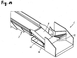
- Fig. 14 shows a variant of the device in which the compensation device is formed by two coupling rods 62.
- the two coupling rods 62 are arranged parallel to each other and of equal length. Both coupling rods are connected at their mutual ends in each case by means of a ball joint (ball head) on the one hand with the telescopic conveyor and on the other hand with the platform or the loading or unloading device 6.
- a ball joint ball head
Landscapes
- Engineering & Computer Science (AREA)
- Mechanical Engineering (AREA)
- Aviation & Aerospace Engineering (AREA)
- Intermediate Stations On Conveyors (AREA)
- Specific Conveyance Elements (AREA)
- Loading Or Unloading Of Vehicles (AREA)
- Framework For Endless Conveyors (AREA)
Abstract
Description
- Die Erfindung betrifft eine Vorrichtung zum Be- oder Entladen eines mit einer Ladeöffnung versehenen Transportbehälters, mit einem Teleskopförderer, der eine Basisfördereinheit und mindestens eine relativ dazu in einer Längsrichtung ausfahrbaren Teleskopfördereinheit aufweist, mit einer Be- oder Entladevorrichtung, die auf einer Fahrebene verfahrbar ist und mittels einer Ausgleichseinrichtung mit dem Teleskopförderer gekoppelt ist, wobei die Ausgleichseinrichtung eine Relativbewegung zwischen der Be- oder Entladevorrichtung und dem Teleskopförderer bezüglich mindestens eines Freiheitsgrads zulässt.
- Eine derartige Be- oder Entladevorrichtung ist aus der
DE 10 2012 003 439 A1 bekannt, wobei es bei der dort beschriebenen Vorrichtung in ungünstigen Situationen mit verengtem Förderkanal aufgrund seitlich ausgelenkter Be- oder Entladeeinheit dazu kommen kann, dass große Stückgutteile am Übergang zwischen der Be- und Entladeeinheit und dem Teleskopförderer hängenbleiben oder sich verklemmen. - Die Aufgabe der Erfindung besteht darin, eine sichere Übergabe jeglicher Stückgutteile von der Be- oder Entladevorrichtung auf den Teleskopförderer bzw. umgekehrt zu gewährleisten.
- Zur Lösung dieser Aufgabe schlägt die Erfindung bei einer gattungsgemäßen Vorrichtung vor, dass zwischen der Be- oder Entladevorrichtung, die auch als Ladevorrichtung bezeichnet werden kann, und einem Kopfende des Teleskopförderers ein Ausgleichsförderer angeordnet ist, der an einem hinteren Ende über ein erstes Gelenk mit dem Teleskopförderer und an einem vorderen Ende über ein zweites Gelenk mit der Be- oder Entladevorrichtung verbünden ist, wobei eines der Gelenke eine Drehbarkeit um zwei zueinander und zu der Längsrichtung senkrechte Drehachsen zulässt und eines der Gelenke eine Drehbarkeit um eine zu der Längsrichtung parallele Drehachse und um zwei zueinander und zu der Längsrichtung senkrechte Drehachsen zulässt, und wobei eines der Gelenke zusätzlich eine begrenzte Ausgleichsbewegung in der Längsrichtung zulässt.
- Ein wesentlicher Vorteil besteht darin, dass der Förderkanal (effektive Durchlassbreite der Vorrichtung) bei gleichem Bauraum breiter gestaltet werden kann, und dass eine erweiterte Ausgleichsmöglichkeit zwischen Teleskopförderer und der Be- oder Entladevorrichtung in horizontaler und vertikaler Richtung erhalten wird.
- Dadurch ist die Gefahr reduziert, dass Stückgüter im Übergangsbereich zwischen Be- oder Entladevorrichtung und Teleskopförderer hängen bleiben.
- Der Ausgleichsförderer ist an beiden Enden drehbar an die Be- oder Entladevorrichtung und den Teleskopförderer angebunden und an einem Ende zusätzlich längsverschiebbar gehalten, so dass eine Ausgleichsmöglichkeit bei jeglicher Relativbewegung zwischen der Be- oder Entladevorrichtung und dem Kopfende des Teleskopförderers möglich ist. Der Ausgleichsförderer kann als Band- oder Gurtförderer oder als Rollenbahn mit angetriebenen und/oder nicht angetriebenen Rollen ausgebildet sein.
- Die Ausgleichseinrichtung kann zwei Koppelstangen aufweisen, mit denen der Teleskopförderer mit der Be- oder Entladevorrichtung verbunden ist. Die Koppelstangen sind bevorzugt parallel und gleich lang, so dass mindestens zwei Freiheitsgrade einer relativen Bewegung erhalten werden, im Wesentlichen entlang einer zur Fahrebene senkrechten Ebene, und gegebenenfalls zusätzliche Drehungsfreiheitsgrade um eine zur Längsachse senkrechte Schwenkachse und/oder um eine zur Längsrichtung parallele Drehachse.
- Die Koppelstangen sind bevorzugt endseitig jeweils mit Kugelgelenken angebunden.
- Bevorzugt ist vorgesehen, dass die Ausgleichseinrichtung eine Schwenkbarkeit der Be- oder Entladevorrichtung relativ zu dem Teleskopförderer um mindestens eine Drehachse zulässt. Eine Drehachse kann durch eine senkrecht zur Längsachse und parallel zur Fahrebene verlaufende Schwenkachse gebildet sein. Eine weitere Drehachse kann parallel zu der Längsachse oder senkrecht zu der Schwenkachse verlaufen. Ein Drehurlgsfreiheitsgrad um eine senkrecht zur Fahrebene verlaufende Achse ist bevorzugt ausgeschlossen.
- Weiterhin lässt die Ausgleichseinrichtung bevorzugt eine lineare Bewegbarkeit der Be- oder Entladevorrichtung relativ zu dem Teleskopförderer in mindestens einer Richtung zu. Die Ausgleichseinrichtung kann eine Bewegbarkeit der Be- oder Entladevorrichtung relativ zu dem Teleskopförderer in einer die Schwenkachse enthaltenden Ebene zulassen. Zur Verwirklichung der Bewegbarkeit in der ersten Richtung kann vorgesehen sein, dass die Ausgleichseinrichtung eine um die Schwenkachse schwenkbar gehaltene erste Linearführung in einer zu der Schwenkachse parallelen ersten Richtung aufweist. Zur Verwirklichung der Bewegbarkeit in der genannten Ebene kann vorgesehen sein, dass die Ausgleichseinrichtung eine von der ersten Linearführung getragene zweite Linearführung in einer zweiten Richtung aufweist, die senkrecht zu der ersten Richtung und in der genannten Ebene verläuft.
- Es kann vorgesehen sein, dass die Be- oder Entladevorrichtung mittels eines Schnellbefestigungsmechanismus oder einer Schnellkoppeleinrichtung lösbar mit dem Teleskopförderer koppelbar ist. Der Schnellbefestigungsmechanismus bzw. die Schnellkoppeleinrichtung ermöglicht bevorzugt eine werkzeuglose, schnell durchführbare An- oder Abkopplung der beiden Komponenten, beispielsweise manuell, pneumatisch oder hydraulisch. Beispielsweise kann ein Rastmechanismus vorgesehen sein, mit dem korrespondierende Rastelemente in Eingriff bringbar und verriegelbar sind.
- Die Ausgleichseinrichtung kann eine erste Anschlussplatte aufweisen, an der eine, und zwar die erste oder zweite Linearführung, und die an dieser Linearführung getragene andere, und zwar die zweite oder erste Linearführung gehalten sind, wobei die andere Linearführung entweder an der einen Komponente, dem Teleskopförderer oder der Be- oder Entladevorrichtung, fixiert ist und die erste Anschlussplatte dauerhaft oder mittels des Schnellbefestigungsmechanismus oder einer Schnellkoppeleinrichtung lösbar mit der anderen Komponente, der Be- oder Entladevorrichtung oder dem Teleskopförderer, koppelbar ist.
- Es kann vorgesehen sein, dass der Schnellbefestigungsmechanismus zwischen der ersten Anschlussplatte und einer zweiten Anschlussplatte angeordnet ist, wobei die zweite Anschlussplatte dauerhaft an der anderen Komponente befestigt ist.
- Die erste Linearführung kann über eine um die Schwenkachse und die dazu senkrechte Drehachse drehbare Gelenkverbindung mit der zweiten Linearführung gekoppelt sein.
- Es kann vorgesehen sein, dass entweder an der Be- oder oder an dem Teleskopförderer zwei parallele beabstandete Linearführungselemente angeordnet sind, an denen je ein erstes Führungsteil geführt ist, wobei an jedem ersten Führungsteil über je ein um die Drehachse drehbares Drehgelenk, das insbesondere als Rundtischlager ausgebildet sein kann, ein zweites Führungsteil gehalten ist und an den zweiten Führungsteilen ein weiteres Linearführungselement um die Schwenkachse schwenkbar gehalten und geführt ist und welches mittels der ersten Anschlussplatte und des Schnellbefestigungsmechanismus mit der jeweils anderen Komponente, der Be- oder Entladevorrichtung oder dem Teleskopförderer, koppelbar sein kann. Insbesondere kann vorgesehen sein, dass die Linearführungselemente Führungsstangen sind.
- Die Be- oder Entladevorrichtung kann als Laderoboter mit einem mehrere Freiheitsgrade aufweisenden Greifarm ausgebildet sein, beispielsweise mit drei, vier, fünf oder sechs Achsen. Zweckmäßigerweise ist zwischen dem Laderoboter und dem Ausgleichsförderer ein Übergangsförderer angeordnet.
- Die Be- oder Entladevorrichtung kann auf einer Plattform angeordnet sein, die auf der Fahrebene gesteuert verfahrbar sein kann.
- Alternativ kann die Be- oder Entladevorrichtung als Ladeförderer mit einem Aufnahmeförderer und einem an diesen anschließenden Übergabeförderer ausgebildet sein, wobei der Übergabeförderer an den Ausgleichsförderer anschließt. Zweckmäßigerweise ist ein Abgabeende des Übergabeförderers oberhalb und überlappend bzgl. des Ausgleichsförderers angeordnet, damit es nicht zu einem Verklemmen von Stückgutteilen kommen kann.
- Bevorzugt ist der Ausgleichsförderer an seinem hinteren Ende oberhalb und überlappend bezüglich des Kopfendes des Teleskopförderers angeordnet, so dass es auch hier nicht zu einem Verklemmen von Stückgutteilen kommen kann.
- Die Erfindung wird nachfolgend anhand eines Ausführungsbeispiels erläutert, wobei auf eine Zeichnung Bezug genommen ist, in der
-
Fig. 1 eine perspektivische Ansicht einer erfindungsgemäßen Vorrichtung zum Be- oder Entladen eines Transportbehälters in einer ersten Lade- bzw. Entladestellung zeigt, wobei die Be- oder Entladevorrichtung als Kombination von zwei Förderern ausgebildet ist, -
Fig. 2 die Vorrichtung nachFig. 1 in einer zweiten Entladestellung der Be- oder Entladevorrichtung zeigt, -
Fig. 3 eine Draufsicht auf die Vorrichtung nachFig. 1 zeigt, in einer Normalposition, -
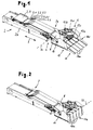
Fig. 4 eine Draufsicht auf die Vorrichtung nachFig. 1 zeigt, in einer ausgelenkten Position ("links"), -
Fig.5 eine Draufsicht ähnlichFig. 3 zeigt, in einer zweiten ausgelenkten Position ("rechts"), -
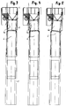
Fig. 6 die Vorrichtung nachFig. 1 bis 4 in einer Seitenansicht zeigt, in einer Position, in der sich die Fahrebene der Be- und Entladevorrichtung auf einer gleichen Höhe mit einer Standebene des Teleskopförderers befindet, -
Fig. 7 eine Ansicht ähnlichFig. 6 zeigt, wobei eine die Fahrebene der Be- oder Entladevorrichtung gegenüber der Stellung nachFig. 6 abgesenkt ist, -
Fig. 8 eine Ansicht ähnlichFig. 6 zeigt, wobei die Fahrebene in einer erhöhten Position dargestellt ist, -
Fig. 9 eine schematische Seitenansicht der Vorrichtung im Bereich des Ausgleichsförderers und der Ausgleichseinrichtung zeigt, -
Fig. 10 schematisch die Freiheitsgrade der Ausgleichseinrichtung zeigt, -
Fig. 11 und 12 die Ausgleichseinrichtung weiter erläutern, -
Fig. 13 die Freiheitsgrade der Gelenke des Ausgleichsförderers erläutert, und -
Fig. 14 eine Ausführungsform mit Koppelstangen erläutert. - Die in den Zeichnungen dargestellte und nachfolgend erläuterte Vorrichtung dient im Wesentlichen dem Entladen eines nicht näher dargestellten Transportbehälters, der mit einer seitlichen Ladeöffnung versehen ist, wie beispielsweise eines Wechselbehälters, Transportbehälters oder LKW-Laderaums, wobei die Vorrichtung als eine wesentliche Komponente einen Teleskopförderer 2 aufweist, der eine Basisfördereinheit 2.0 und eine Anzahl von relativ dazu teleskopartig ausfahrbaren Teleskopfördereinheiten 2.1, 2.2, 2.3, 2.4, 2.5 und 2.6 (insbes.
Fig. 5 ) umfasst. Eine Ausfahrrichtung der Teleskopförderelemente ist parallel zu einer Förderrichtung oder Längsrichtung 3, in der der Teleskopförderer antreibbar ist. In der dargestellten Ausführung weist jede einzelne Teleskopfördereinheit 2.1 ... 2.6 ein eigenes, endlos umlaufendes Förderband auf. Eine letzte oder oberste Teleskopfördereinheit 2.6 bildet mit ihrem vorderen Ende ein Kopfende 2a des Teleskopförderers. Eine Längsmittellinie des Teleskopförderers ist mit 2c bezeichnet (Fig. 3 bis 5 ). - An einem vorderen Ende des Teleskopförderers 2, wobei auch auf
Fig. 9 und13 verwiesen sei, ist als weitere wesentliche Komponente der Vorrichtung mittels einer Ausgleichseinrichtung 5 eine Be- oder Entladevorrichtung 6 angekoppelt, wobei ein Ausgleichsförderer 8 als weitere wesentliche Komponente der Vorrichtung einen Übergangsbereich zwischen dem Kopfende 2a des Teleskopförderers 2 und der Be- oder Entladevorrichtung 6 überbrückt. Der Ausgleichsförderer 8 ist an seinem hinteren, dem Teleskopförderer 2 zugekehrten Ende über ein erstes in allen Richtungen drehbares Gelenk 8a mit dem Teleskopförderer 2 verbunden, das mit anderen Worten eine Schwenkbewegung um zwei zueinander und zu der Längsrichtung 3 senkrechte Drehachsen 8.1, 8.2, eine Drehbewegung um eine zur Längsrichtung 3 parallele Drehachse 8.3 und zusätzlich eine lineare Ausgleichsbewegung in Längsrichtung 3 zulässt. An seinem vorderen Ende ist der Ausgleichsförderer 8 über ein zweites Gelenk 8b mit der Plattform 14 bzw. mit der Be- oder Entladevorrichtung 6 verbunden, das eine Schwenkbewegung um zwei zueinander und zu der Längsrichtung senkrechte Drehachsen 8.4, 8.5 zulässt. Gelenk 8b kann somit nicht um eine zur Längsrichtung 3 parallele Achse verschwenkt werden. - Die Be- oder Entladevorrichtung 6 kann als beliebige Ladevorrichtung ausgebildet sein, beispielsweise als Laderoboter mit einem Greifer mit mehreren Freiheitsgraden, oder wie dargestellt in Form einer Fördervorrichtung, die in dem dargestellten Ausführungsbeispiel zwei miteinander zusammenwirkende Förderer umfasst. Ein Aufnahmeförderer 10 dient der unmittelbaren Aufnahme eines Stückgutteils vom Boden oder von einer gestapelten Position, während ein an den Aufnahmeförderer 10 anschließender Übergabeförderer 12 dem weiteren Transport der Stückgutteile zu dem Ausgleichsförderer 8 dient.
- Die Be- oder Entladevorrichtung 6 in Form des Aufnahmeförderers 10 und Übergabeförderers 12 mit Längsmittellinie 6a sowie ein vorderes, an den Übergabeförderer 12 anschließendes Ende des Ausgleichsförderers 8 sind auf einer Plattform 14 angeordnet, die auf einem ebenen Untergrund oder einer Fahrebene 16 verfahrbar ist. Eine Bewegung der Plattform 14 in Längsrichtung 3, d.h. in und entgegen der Förderrichtung des Teleskopförderers, erfolgt durch eine entsprechend gesteuerte Bewegung des mit der Plattform 14 über die Ausgleichseinrichtung 5 gekoppelten Teleskopförderers 2, während eine Verfahrbewegung der Plattform quer zur Längsrichtung 3 durch eine entsprechende gesteuerte Lenkung von Rädern erfolgt, auf denen die Plattform auf dem Untergrund 16 verfahrbar ist.
- Die Basisfördereinheit 2.0 ist an einem darunter befindlichen Maschinengestell 2b des Teleskopförderers 2 gehalten, welches auf einem Untergrund steht oder in Längsrichtung antreibbar und verfahrbar ist. Eine an ein hinteres Ende des Teleskopförderers 2 anschließende Fördertechnik, beispielsweise Sortiertechnik, ist nicht dargestellt.
- Der Aufnahmeförderer 10 besteht aus einer Reihe von beispielsweise vier nebeneinander angeordneten einzelnen Aufnahmeförderelementen 10a, beispielsweise Gurtförderern, wobei jedes Aufnahmeförderelement 10a aktiv oder passiv längenanpassbar ist, was in
Fig. 1 für ein Aufnahmeförderelement 10a beispielhaft dargestellt ist. Bei passiver Längenanpassbarkeit verkürzt sich das Aufnahmeförderelement 10a bei einer entsprechenden, gegen ein vorderes Aufnahmeende 10b des Aufnahmeförderers 10 wirkenden Kraft gegen eine Rückstellkraft und verlängert sich bei Wegfall der Kraft selbsttätig wieder bis auf seine Ausgangslänge. - Der Übergabeförderer 12 ist in der dargestellten Ausführungsform mehrfach unterteilt und besteht aus vier nebeneinander angeordneten Übergabeförderelementen 12a in Form von Bandförderern, einem nachgeordneten weiteren Bandförderer 12b sowie einer seitlich angeordneten Rollenbahn 12c, die eine im Wesentlichen dreieck- oder trapezförmige Förderoberfläche bildet. Die Rollenbahn 12c hat schräg zur Längsrichtung 3 angeordnete Rollen, um eine zu einer vertikalen Längsmittelebene des Teleskopförderers 2 gerichtete Förderkomponente zu erzielen. An einem äußeren Rand der Rollenbahn 12c sowie an einem gegenüberliegenden Rand des Bandförderers 12b sind seitliche Leitbleche 12d angeordnet, um Stückgutteile in Richtung des Ausgleichsförderers 8 zu lenken.
- Anhand der unterschiedlichen Stellungen von Aufnahme- und Übergabeförderer 10, 12 in
Fig. 1 und 2 ist erkennbar, dass der Übergabeförderer 12 an einem Übergabeende 12e um eine erste Schwenkachse 20, die horizontal und quer zur Längsrichtung 3 angeordnet ist, verschwenkbar gehalten ist, so dass der Übergabeförderer 12 in seinem vorderen Bereich, insbesondere an einem Übernahmeende 12f, höhenverstellbar ist. - Der Aufnahmeförderer 10 ist um eine zweite Schwenkachse 22, die benachbart zu und insbesondere an dem Übernahmeende 12f des Übergabeförderers 12 horizontal und quer zur Förderrichtung 3 angeordnet ist, höhenverschwenkbar an dem Übergabeförderer 12 gehalten, so dass ein vorderstes Aufnahmeende 10b des Aufnahmeförderers 10 unabhängig von einer Höhenverstellung des Übernahmeendes 12f des Übernahmeförderers 12 verschwenkbar und höhenverstellbar ist.
- Die zweite Schwenkachse 22 verläuft bei Ausbildung des Aufnahmeförderers 10 als Band- oder Rollenförderer bevorzugt durch eine an einem Abgabeende 10c des Aufnahmeförderers 10 angeordnete Antriebs- oder Umlenkrolle des Aufnahmeförderers 10, oder durch eine am Übernahmeende 12f des Übergabeförderers 12 angeordnete Antriebs- oder Umlenkrolle.
-
Fig. 1 zeigt eine untere Entladestellung der Vorrichtung, bei der sich das Aufnahmeende 10b des Aufnahmeförderers auf dem oder unmittelbar oberhalb des Untergrunds 16 befindet und Aufnahmeförderer und Übergabeförderer 10, 12 eine im Wesentlichen gleiche Neigung in Bezug auf die Horizontale oder den Untergrund 16 aufweisen, so dass auf dem Boden liegende oder aufgehäufte Stückgutteile durch Antrieb von Aufnahmeförderer 10 und Übergabeförderer 12 in Förderrichtung 3 aufnehmbar und in Richtung des Teleskopförderers 2 förderbar sind. -
Fig. 2 zeigt eine andere Entladestellung, in der der Aufnahmeförderer 10 um die zweite Schwenkachse 22 im Wesentlichen vertikal geschwenkt ist und höher gestapelte Stückgutteile von dem Übergabeförderer 12 aufnehmbar sind. -
Fig. 3 bis 8 dienen der Erläuterung der Ausgleichseinrichtung 5, mittels der die Plattform 14 zusammen mit der darauf befindlichen Be- oder Entladevorrichtung 6 mit dem Teleskopförderer 2 lösbar gekoppelt ist. Die Ausgleichseinrichtung 5 ermöglicht über Ausgleichselemente zunächst eine Schwenkbewegung der Plattform 14 relativ zu dem Teleskopförderer 2 um eine parallel zur Fahrebene 16 und quer zur Längsrichtung 3 orientierte Schwenkachse 30 (Fig. 1 ,4 ,5 ,6 ) und weiterhin eine Dreh- bzw. Schwenkbewegung um eine senkrecht zu der Schwenkachse 30 orientierte Drehachse 58. - Weiterhin ermöglicht die Ausgleichseinrichtung 5 eine begrenzte horizontale Verlagerbarkeit der Plattform 14 relativ zu dem Teleskopförderer 2, parallel zu der Fahrebene 16, wobei eine solche seitliche Bewegung und eine entsprechende Stellung des Ausgleichsförderers 8 in
Fig. 4 und 5 im Unterschied zu einer Neutralstellung gemäßFig. 3 dargestellt ist. - Schließlich ermöglicht die Ausgleichseinrichtung 5 eine begrenzte Verlagerbarkeit der Plattform 14 relativ zu dem Teleskopförderer 2 in einer zu der Richtung der horizontalen Verlagerbarkeit senkrechten Richtung in einer Ebene 32, die senkrecht zu der Drehachse 58 ist und beispielsweise senkrecht zur Längsrichtung 3 und zur Fahrebene 16 orientiert sein kann.
Fig. 6 und 7 zeigen beispielhaft Verlagerungen der Plattform 14 unterhalb und oberhalb einer Neutralstellung gemäßFig. 5 . Die Ebene 32 liegt inFig. 5 senkrecht zur Darstellungsebene. -
Fig. 10 bis 12 erläutern beispielhaft den Aufbau der Ausgleichseinrichtung 5 und der davon umfassten Ausgleichselemente, mit denen die Plattform 14 mit dem Teleskopförderer 2 gekoppelt werden kann, wobei die vorstehend beschriebenen Freiheitsgrade einer relativen Bewegung zwischen den beiden Komponenten erhalten werden, sowie schematisch den Schnellbefestigungsmechanismus 4. - An der Plattform 14 sind zwei parallele beabstandete Linearführungselemente in Form von Führungsstangen 42 angeordnet, die die Ebene 32 definieren. An jeder Führungsstange 42 ist ein erstes Führungsteil 44 längsverschieblich geführt, beispielsweise als Hülse durch formschlüssiges Umgreifen der Führungsstange 42 oder nach Art einer Kugelbüchse. An jedem ersten Führungsteil 44 ist über ein Drehgelenk 46, beispielsweise Rundtischlager, ein zweites Führungsteil 48 gehalten, welches aufgrund des Drehgelenks 46 um eine zu der Schwenkachse 30 senkrechte Drehachse 50 relativ zu dem ersten Führungsteil 44 drehbar ist. An den beiden zweiten Führungsteilen 48 ist ein weiteres Linearführungselement in Form einer Führungsstange 52 in Richtung der Schwenkachse 30 längsverschieblich gehalten und geführt, wobei die zweiten Führungsteile 48 in Richtung der Schwenkachse 30 auf der Führungsstange 52 verschieblich sind, beispielsweise als Hülse durch formschlüssiges Umschließen der Führungsstange 52 oder nach Art einer Kugelbüchse.
- Die Führungsstange 52 ist schließlich über eine erste Anschlussplatte 40 mittels eines Schnellbefestigungsmechanismus 4, d.h. bevorzugt werkzeuglos, lösbar an dem Teleskopförderer 2 gehalten, so dass sich die in
Fig. 10 und 11 gezeigten Freiheitsgrade zwischen Plattform 14 und Teleskopförderer 2 ergeben. Diese bestehen zunächst aus einer Schwenkbarkeit um die parallel zur Fahrebene 16 und senkrecht zur Längsrichtung 3 angeordnete Schwenkachse 30 und weiterhin aus den beiden linearen Verschiebemöglichkeiten in der Ebene 32, veranschaulicht durch einen horizontalen linearen Freiheitsgrad 54 als erste Richtung und einen dazu senkrechten, insbesondere vertikalen linearen Freiheitsgrad 56 als zweite Richtung (Fig. 10 ). Hinzu kommt eine relative Verdrehbarkeit zwischen Plattform 14 und Teleskopförderer 2 um eine parallel zu den Drehachsen 50 angeordnete Drehachse 58, die senkrecht zu der Ebene 32 und den Führungsstangen 42 orientiert ist. -
Fig. 9 zeigt schematisch, dass die Ausgleichseinrichtung 5 an der Plattform 14 bzw. an der Be- und Entladevorrichtung 6 gehalten ist, wobei die erste Anschlussplatte 40 benachbart dazu dargestellt ist. Zur lösbaren Ankopplung an den Teleskopförderer 2 dient der Schnellbefestigungsmechanismus 4, der die erste Anschlussplatte 40 mit einer fest mit dem Teleskopförderer 2 verbundenen zweiten Anschlussplatte 60 verbindet. -
Fig. 14 zeigt eine Variante der Vorrichtung, bei der die Ausgleichseinrichtung durch zwei Koppelstangen 62 gebildet ist. Die beiden Koppelstangen 62 sind parallel zueinander angeordnet und gleich lang. Beide Koppelstangen sind an ihren beiderseitigen Enden jeweils mittels eines Kugelgelenks (Kugelkopf) einerseits mit dem Teleskopförderer und andererseits mit der Plattform bzw. der Be- oder Entladevorrichtung 6 verbunden. -
- 2
- Teleskopförderer
- 2a
- Kopfende
- 2b
- Maschinengestell
- 2c
- Längsmittellinie
- 2.0
- Basisfördereinheit
- 2.1 ... 2.6
- Teleskopfördereinheit
- 3
- Förderrichtung (Längsrichtung)
- 4
- Schnellbefestigungsmechanismus (Schnellkoppeleinrichtung)
- 5
- Ausgleichseinrichtung
- 6
- Be- oder Entladevorrichtung
- 6a
- Längsmittellinie
- 8
- Ausgleichsförderer
- 8a
- erstes Gelenk
- 8b
- zweites Gelenk
- 8.1, 8.2, 8.3
- Drehachsen (von 8a)
- 8.4, 8.5
- Drehachsen (von 8b)
- 10
- Aufnahmeförderer
- 10a
- Aufnahmeförderelement
- 10b
- Aufnahmeende
- 10c
- Abgabeende
- 12
- Übergabeförderer
- 12a
- Übergabeförderelement
- 12b
- Bandförderer
- 12c
- Rollenbahn
- 12d
- Leitblech
- 12e
- Übergabeende
- 12f
- Übernahmeende
- 14
- Plattform
- 16
- Untergrund (Fahrebene)
- 20
- erste Schwenkachse
- 22
- zweite Schwenkachse
- 30
- Schwenkachse
- 32
- Ebene
- 40
- erste Anschlussplatte
- 42
- Führungsstange (Linearführungselement)
- 44
- erstes Führungsteil
- 46
- Drehgelenk
- 48
- zweites Führungsteil
- 50
- Drehachse
- 51
- Pfeil (Drehachse 50)
- 54
- horizontaler Freiheitsgrad (erste Richtung)
- 56
- vertikaler Freiheitsgrad (zweite Richtung)
- 58
- Drehachse
- 60
- zweite Anschlussplatte
- 62
- Koppelstange
Claims (14)
- Vorrichtung zum Be- oder Entladen eines mit einer Ladeöffnung versehenen Transportbehälters, mit einem Teleskopförderer (2), der eine Basisfördereinheit (2.0) und mindestens eine relativ dazu in einer Längsrichtung (3) ausfahrbare Teleskopfördereinheit (2.1 ... 2.6) aufweist, mit einer Be- oder Entladevorrichtung (6), die auf einer Fahrebene (16) verfahrbar ist und mittels einer Ausgleichseinrichtung (5) mit dem Teleskopförderer (2) gekoppelt ist, wobei die Ausgleichseinrichtung (5) eine Relativbewegung zwischen der Be- oder Entladevorrichtung (6) und dem Teleskopförderer (2) bezüglich mindestens eines Freiheitsgrades zulässt, dadurch gekennzeichnet, dass zwischen der Be- oder Entladevorrichtung (6) und einem Kopfende (2a) des Teleskopförderers (2) ein Ausgleichsförderer (8) angeordnet ist, der an einem hinteren Ende über ein erstes Gelenk (8a) mit dem Teleskopförderer (2) und an einem vorderen Ende über ein zweites Gelenk (8b) mit der Be- oder Entladevorrichtung (6) verbunden ist, wobei eines der Gelenke (8a, 8b) eine Drehbarkeit um zwei zueinander und zu der Längsrichtung (3) senkrechte Drehachsen zulässt und eines der Gelenke (8a, 8b) eine Drehbarkeit um eine zu der Längsrichtung (3) parallele Drehachse und um zwei zueinander und zu der Längsrichtung (3) senkrechte Drehachsen zulässt, und wobei eines der Gelenke (8a, 8b) zusätzlich eine begrenzte Ausgleichsbewegung in der Längsrichtung (3) zulässt.
- Vorrichtung nach Anspruch 1, dadurch gekennzeichnet, dass die Ausgleichseinrichtung (5) zwei Koppelstangen aufweist, mit denen der Teleskopförderer (2) mit der Be- oder Entladevorrichtung (6) verbunden ist.
- Vorrichtung nach Anspruch 1 oder 2, dadurch gekennzeichnet, dass die Ausgleichseinrichtung (5) eine Schwenkbarkeit der Be- oder Entladevorrichtung (6) relativ zu dem Teleskopförderer (2) um mindestens eine Drehachse (30, 58) zulässt.
- Vorrichtung nach Anspruch 3, dadurch gekennzeichnet, dass eine Drehachse durch eine senkrecht zu der Längsrichtung (3) und parallel zu der Fahrebene (16) verlaufende Schwenkachse (30) gebildet ist.
- Vorrichtung nach einem der vorangehenden Ansprüche, dadurch gekennzeichnet, dass die Ausgleichseinrichtung (5) eine lineare Bewegbarkeit der Be- oder Entladevorrichtung (6) relativ zu dem Teleskopförderer (2) in mindestens einer Richtung (54, 56) zulässt.
- Vorrichtung nach Anspruch 4, dadurch gekennzeichnet, dass die Ausgleichseinrichtung (5) eine Bewegbarkeit der Be- oder Entladevorrichtung (6) relativ zu dem Teleskopförderer (2) in einer die Schwenkachse (30) enthaltenden Ebene (32) zulässt.
- Vorrichtung nach Anspruch 4, dadurch gekennzeichnet, dass die Ausgleichseinrichtung (5) eine um die Schwenkachse (30) schwenkbar gehaltene erste Linearführung (52, 48) in einer zu der Schwenkachse (30) parallelen ersten Richtung (54) aufweist.
- Vorrichtung nach Anspruch 6 und 7, dadurch gekennzeichnet, dass die Ausgleichseinrichtung (5) eine von der ersten Linearführung (52, 48) getragene zweite Linearführung (42, 44) in einer zweiten Richtung (56) aufweist, die senkrecht zu der ersten Richtung (54) und in der Ebene (32) verläuft.
- Vorrichtung nach einem der vorangehenden Ansprüche, dadurch gekennzeichnet, dass die Be- oder Entladevorrichtung (6) mittels einer Schnellkoppeleinrichtung (4) lösbar mit dem Teleskopförderer (2) koppelbar ist.
- Vorrichtung nach Anspruch 7, 8 und 9, dadurch gekennzeichnet, dass die Ausgleichseinrichtung (5) eine erste Anschlussplatte (40) aufweist, an der eine, und zwar die erste oder zweite Linearführung, und die an dieser Linearführung getragene andere, und zwar die zweite oder erste Linearführung gehalten sind, wobei die andere Linearführung entweder an der einen Komponente, dem Teleskopförderer (2) oder der Be- oder Entladevorrichtung (6), fixiert ist und die erste Anschlussplatte (40) dauerhaft oder mittels der Schnellkoppeleinrichtung (4) lösbar an der anderen Komponente, der Be- oder Entladevorrichtung (6) oder dem Teleskopförderer (2), gehalten ist.
- Vorrichtung nach Anspruch 10, dadurch gekennzeichnet, dass die Schnellkoppeleinrichtung (4) zwischen der ersten Anschlussplatte (40) und einer zweiten Anschlussplatte (60) angeordnet ist, wobei die zweite Anschlussplatte (60) dauerhaft an der anderen Komponente befestigt ist.
- Vorrichtung nach einem der Ansprüche 8 bis 10, dadurch gekennzeichnet, dass die erste Linearführung (52, 48) über eine um die Schwenkachse (30) und die dazu senkrechte Drehachse (58) drehbare Gelenkverbindung mit der zweiten Linearführung (42, 44) gekoppelt ist.
- Vorrichtung nach Anspruch 12, dadurch gekennzeichnet, dass entweder an der Be- oder Entladevorrichtung (6) oder an dem Teleskopförderer (2) zwei parallele beabstandete Linearführungselemente (42) angeordnet sind, an denen je ein erstes Führungsteil (44) geführt ist, wobei an jedem ersten Führungsteil (44) über je ein um die Drehachse (58) drehbares Drehgelenk (46) ein zweites Führungsteil (48) gehalten ist und an den zweiten Führungsteilen (48) ein weiteres Linearführungselement (52) um die Schwenkachse (30) schwenkbar gehalten und geführt ist.
- Vorrichtung nach Anspruch 13, dadurch gekennzeichnet, dass das weitere Linearführungselement (52) mittels der Anschlussplatte (40) und der Schnellkoppeleinrichtung (4) mit der Be- oder Entladevorrichtung (6) oder mit dem Teleskopförderer (2) koppelbar ist.
Applications Claiming Priority (1)
| Application Number | Priority Date | Filing Date | Title |
|---|---|---|---|
| DE102015003239.9A DE102015003239A1 (de) | 2015-03-10 | 2015-03-10 | Vorrichtung zum Be- oder Entladen einen Transportbehälters |
Publications (2)
| Publication Number | Publication Date |
|---|---|
| EP3067298A1 true EP3067298A1 (de) | 2016-09-14 |
| EP3067298B1 EP3067298B1 (de) | 2021-04-28 |
Family
ID=55661030
Family Applications (1)
| Application Number | Title | Priority Date | Filing Date |
|---|---|---|---|
| EP16000551.8A Active EP3067298B1 (de) | 2015-03-10 | 2016-03-08 | Vorrichtung zum be- oder entladen eines transportbehälters |
Country Status (4)
| Country | Link |
|---|---|
| US (1) | US10618752B2 (de) |
| EP (1) | EP3067298B1 (de) |
| DE (1) | DE102015003239A1 (de) |
| DK (1) | DK3067298T3 (de) |
Cited By (1)
| Publication number | Priority date | Publication date | Assignee | Title |
|---|---|---|---|---|
| US10618752B2 (en) | 2015-03-10 | 2020-04-14 | BEUMER Group GmbH & Co. KG | Device for loading or unloading of a transport container |
Families Citing this family (22)
| Publication number | Priority date | Publication date | Assignee | Title |
|---|---|---|---|---|
| JP2018509359A (ja) * | 2015-03-24 | 2018-04-05 | ハート、ジョン イー.HART, John E. | ローディングシステム |
| CN110049933A (zh) | 2016-12-06 | 2019-07-23 | 伯克希尔格雷股份有限公司 | 用于提供车辆中的物体处理的系统和方法 |
| US10618745B2 (en) | 2016-12-09 | 2020-04-14 | Berkshire Grey, Inc. | Systems and methods for processing objects provided in vehicles |
| DE102017002478A1 (de) * | 2017-03-14 | 2018-09-20 | SAMA GmbH | Vorrichtung zur aufnahme von gestapelten objekten |
| EP3441331B8 (de) * | 2017-08-09 | 2022-11-02 | Körber Supply Chain Logistics GmbH | Verfahren zum handling von sortierstücken mit überwachten teleskopförderbändern |
| US10435246B2 (en) * | 2017-08-30 | 2019-10-08 | Rite-Hite Holding Corporation | Extendible fences for extendible conveyors |
| AU2018250517B2 (en) * | 2017-10-20 | 2024-04-11 | YGCC Holdings Pty Ltd | Apparatus for use in unpacking shipping containers |
| US10577201B2 (en) * | 2017-11-08 | 2020-03-03 | Walmart Apollo, Llc | Automated vehicle loading |
| DE102017011880B4 (de) * | 2017-12-21 | 2020-06-04 | Gawronski Gmbh | Teleskopförderer |
| US10583995B2 (en) | 2018-06-26 | 2020-03-10 | Caterpillar Paving Products, Inc. | Flexible hopper for a conveyor system |
| US10589933B2 (en) * | 2018-06-26 | 2020-03-17 | Caterpillar Paving Products Inc. | Flexible hopper for a conveyor system |
| EP3636566B1 (de) * | 2018-10-10 | 2023-03-22 | Tata Consultancy Services Limited | Vorrichtung zum be- und entladen von fracht |
| CN113382940B (zh) | 2019-02-27 | 2023-11-07 | 伯克希尔格雷营业股份有限公司 | 用于通过振动来控制物体在容器中的卸放的系统和方法 |
| CN110104461A (zh) * | 2019-05-09 | 2019-08-09 | 杨国金 | 可用于智能装车的伸缩式输送线 |
| US11702302B2 (en) * | 2019-07-31 | 2023-07-18 | Körber Supply Chain Llc | Automated unloading speed control |
| CN112591496A (zh) * | 2020-12-15 | 2021-04-02 | 姜堰经济开发区科创中心 | 一种火车棚车袋装货物自动装车系统 |
| US11691823B1 (en) * | 2021-03-30 | 2023-07-04 | Amazon Technologies, Inc. | Adjustable conveyor system |
| CN113173434A (zh) * | 2021-05-20 | 2021-07-27 | 浙江微通智能科技有限公司 | 一种自动化装车设备 |
| CN113816172B (zh) * | 2021-09-26 | 2024-04-05 | 北京京东乾石科技有限公司 | 一种卸货机及卸货系统 |
| US11866269B2 (en) | 2021-10-06 | 2024-01-09 | Berkshire Grey Operating Company, Inc. | Dynamic processing of objects provided in elevated vehicles with evacuation systems and methods for receiving objects |
| US20240189982A1 (en) * | 2022-12-12 | 2024-06-13 | Mujin, Inc. | Robotic system with object handling mechanism for loading and unloading of cargo carriers |
| US12280969B2 (en) * | 2023-09-14 | 2025-04-22 | Target Brands, Inc. | Depalletization systems and methods |
Citations (6)
| Publication number | Priority date | Publication date | Assignee | Title |
|---|---|---|---|---|
| FR2085385A1 (de) * | 1970-04-15 | 1971-12-24 | Ameco Sa | |
| DE2230113A1 (de) * | 1972-06-21 | 1974-01-10 | Mash Sawod Im Karla Libknechta | Einrichtung zum beladen von eisenbahnwagen |
| US5718325A (en) * | 1992-11-13 | 1998-02-17 | Doster; John | Adjustable conveyor system for man-loaded cargos |
| US20050258015A1 (en) * | 2003-02-05 | 2005-11-24 | Kinzer Dwight E | Track-and-trolley conveyor guidance system |
| DE102012003439A1 (de) | 2012-02-09 | 2013-08-14 | Beumer Gmbh & Co. Kg | Vorrichtung und Verfahren zum Entladen von Stückgut aus einem Laderaum |
| WO2014174005A1 (de) * | 2013-04-26 | 2014-10-30 | J. Schmalz Gmbh | Fördereinrichtung zum beladen oder entladen von vereinzelbarem stückgut |
Family Cites Families (41)
| Publication number | Priority date | Publication date | Assignee | Title |
|---|---|---|---|---|
| US3049251A (en) * | 1960-11-17 | 1962-08-14 | John A Glew | Commercial carrier bulk unloading device |
| DE1481347A1 (de) * | 1967-01-04 | 1969-07-03 | Moellers Maschf E | Fahrbare Foerderbandanlage |
| US3819068A (en) * | 1973-01-02 | 1974-06-25 | Fmc Corp | Boom conveyor |
| US4436188A (en) * | 1981-11-18 | 1984-03-13 | Jones Cecil R | Controlled motion apparatus |
| US4537554A (en) * | 1983-01-14 | 1985-08-27 | The United States Of America As Represented By The Administrator Of The National Aeronautics And Space Administration | Shuttle car loading system |
| US5088873A (en) * | 1988-12-06 | 1992-02-18 | Yellow Freight System, Inc. | Manipulator mixed freight handling system |
| US5009560A (en) * | 1988-12-06 | 1991-04-23 | Yellow Freight System, Inc. | Mixed freight handling system |
| US5351809A (en) * | 1993-04-26 | 1994-10-04 | Rapistan Demag Corporation | Multiple-stage extendable conveyor |
| US5697753A (en) * | 1995-09-19 | 1997-12-16 | Recot, Inc. | Semiautomatic stacker for stackable articles |
| FR2741292B1 (fr) * | 1995-11-21 | 1998-01-16 | Onera (Off Nat Aerospatiale) | Appareil de telemanipulation du type "maitre-esclave" a six degres de liberte |
| US6006893A (en) * | 1996-04-24 | 1999-12-28 | Mannesmann Dematic Rapistan Corp. | Extendable trailer loader/unloader with user interface section |
| US6431346B1 (en) * | 1996-04-24 | 2002-08-13 | Rapistan Systems Advertising Corp. | Extendable trailer loader/unloader with user interface section |
| US6281651B1 (en) * | 1997-11-03 | 2001-08-28 | Immersion Corporation | Haptic pointing devices |
| SE512931C2 (sv) * | 1998-04-29 | 2000-06-05 | Abb Ab | Anordning för relativ förflyttning av två element |
| US6481563B1 (en) * | 1999-12-29 | 2002-11-19 | Rapistan Systems Advertising Corp. | Extendable conveyor with additional boom section |
| US6484862B1 (en) * | 2000-07-18 | 2002-11-26 | Rapistan Systems Advertising Corp. | Extendable gravity loader |
| RU2312044C2 (ru) * | 2002-03-11 | 2007-12-10 | Телэр Интернэшнл Аб | Система для погрузки неупакованного груза в грузовой отсек самолета и выгрузки неупакованного груза из грузового отсека самолета и используемые для этого средство промежуточного конвейера и блок конвейера |
| DE10255843B4 (de) * | 2002-11-29 | 2012-06-06 | Caljan Rite-Hite Aps | Teleskopfördereinrichtung |
| PL1628896T3 (pl) * | 2003-05-02 | 2012-12-31 | Metso Minerals Inc | Przenośnik poprzeczny i ruchome podwozie obejmujące taki przenośnik poprzeczny |
| US7134829B2 (en) * | 2004-03-09 | 2006-11-14 | Absolute Electronic Solutions, Inc. | Cargo trailer |
| US7731021B2 (en) * | 2004-12-20 | 2010-06-08 | Laitram, L.L.C. | Conveyor link chain with universal coupling joint |
| DK1879822T3 (da) * | 2005-05-02 | 2013-05-27 | Univeyor As | System til aflæsning eller pålæsning af stykgods |
| US7370753B2 (en) * | 2005-07-12 | 2008-05-13 | Siemens Energy & Automation, Inc. | Extendable conveyor with boom brake |
| US7451866B2 (en) * | 2006-06-08 | 2008-11-18 | Nmc-Wollard, Inc. | Conveying device |
| US7819270B1 (en) * | 2007-07-19 | 2010-10-26 | Hughes Michael R | Telescoping material handling bin |
| FR2937854B1 (fr) * | 2008-10-31 | 2010-12-03 | Aripa Services Innovations Ind | Dispositif pour positionner un patient par rapport a un rayonnement. |
| JP2011194428A (ja) * | 2010-03-18 | 2011-10-06 | Aida Engineering Ltd | 搬送装置の破損防止機構およびそれを用いた搬送装置 |
| US8651794B2 (en) * | 2010-04-22 | 2014-02-18 | Siemens Industry, Inc. | Automated bed-loaded container unloader and method |
| FR2963304B1 (fr) * | 2010-07-30 | 2018-02-02 | Lohr Industrie | Systeme universel de chargement/dechargement et de transport ferroviaire de semi-remorques routieres |
| DE102010037472A1 (de) * | 2010-09-10 | 2012-03-15 | Wipotec Wiege- Und Positioniersysteme Gmbh | Vorrichtung zum Ein- und/oder Ausladen von Gütern in und/oder aus einem Laderaum, insbesondere eines Containers |
| US8944239B2 (en) * | 2010-10-26 | 2015-02-03 | Engineered Lifting Systems & Equipment Inc. | Conveyor apparatus for loading or unloading packages from shipping containers |
| US8464859B2 (en) * | 2010-10-26 | 2013-06-18 | Engineered Lifting Systems & Equipment Inc. | Conveyor apparatus for unloading packages from shipping containers |
| CH704136A1 (de) * | 2010-11-26 | 2012-05-31 | Ferag Ag | Förderkette für ein fördermittel einer fördereinrichtung. |
| US8622199B2 (en) * | 2010-12-23 | 2014-01-07 | Rite-Hite Holding Corporation | Adjustable conveyor extensions |
| EP2508451A1 (de) * | 2011-04-06 | 2012-10-10 | Precision Automation and Robotics India Ltd. | Frachthandhabungssystem |
| JP5715304B2 (ja) * | 2011-07-27 | 2015-05-07 | エコール ポリテクニーク フェデラル デ ローザンヌ (イーピーエフエル) | 遠隔操作のための機械的遠隔操作装置 |
| US20140150593A1 (en) * | 2012-12-05 | 2014-06-05 | Alio Industries, Inc. | Precision tripod motion system |
| US9045289B2 (en) * | 2013-05-03 | 2015-06-02 | Siemens Industry, Inc. | Universal safety device for extendible conveyors |
| US8978871B1 (en) * | 2013-05-22 | 2015-03-17 | Amazon Technologies, Inc. | Conveyor system |
| CA2910774A1 (en) * | 2014-10-29 | 2016-04-29 | Septimatech Group Inc. | Lane adjustment system |
| DE102015003239A1 (de) | 2015-03-10 | 2016-09-15 | Beumer Gmbh & Co. Kg | Vorrichtung zum Be- oder Entladen einen Transportbehälters |
-
2015
- 2015-03-10 DE DE102015003239.9A patent/DE102015003239A1/de not_active Ceased
-
2016
- 2016-03-08 EP EP16000551.8A patent/EP3067298B1/de active Active
- 2016-03-08 DK DK16000551.8T patent/DK3067298T3/da active
- 2016-03-08 US US15/063,734 patent/US10618752B2/en active Active
Patent Citations (6)
| Publication number | Priority date | Publication date | Assignee | Title |
|---|---|---|---|---|
| FR2085385A1 (de) * | 1970-04-15 | 1971-12-24 | Ameco Sa | |
| DE2230113A1 (de) * | 1972-06-21 | 1974-01-10 | Mash Sawod Im Karla Libknechta | Einrichtung zum beladen von eisenbahnwagen |
| US5718325A (en) * | 1992-11-13 | 1998-02-17 | Doster; John | Adjustable conveyor system for man-loaded cargos |
| US20050258015A1 (en) * | 2003-02-05 | 2005-11-24 | Kinzer Dwight E | Track-and-trolley conveyor guidance system |
| DE102012003439A1 (de) | 2012-02-09 | 2013-08-14 | Beumer Gmbh & Co. Kg | Vorrichtung und Verfahren zum Entladen von Stückgut aus einem Laderaum |
| WO2014174005A1 (de) * | 2013-04-26 | 2014-10-30 | J. Schmalz Gmbh | Fördereinrichtung zum beladen oder entladen von vereinzelbarem stückgut |
Cited By (1)
| Publication number | Priority date | Publication date | Assignee | Title |
|---|---|---|---|---|
| US10618752B2 (en) | 2015-03-10 | 2020-04-14 | BEUMER Group GmbH & Co. KG | Device for loading or unloading of a transport container |
Also Published As
| Publication number | Publication date |
|---|---|
| EP3067298B1 (de) | 2021-04-28 |
| US10618752B2 (en) | 2020-04-14 |
| DK3067298T3 (da) | 2021-07-05 |
| US20160264366A1 (en) | 2016-09-15 |
| DE102015003239A1 (de) | 2016-09-15 |
Similar Documents
| Publication | Publication Date | Title |
|---|---|---|
| EP3067298B1 (de) | Vorrichtung zum be- oder entladen eines transportbehälters | |
| EP2794433B1 (de) | Kommissionieranlage sowie verfahren zum kommissionieren von artikeln | |
| EP2961674B1 (de) | Fördereinrichtung zum beladen oder entladen von vereinzelbarem stückgut | |
| EP1826154B1 (de) | Förderband zum Transportieren von Gegenständen | |
| DE102021106634B3 (de) | Halte- und Positioniervorrichtung für Werkstücke | |
| EP2921435B1 (de) | Umlenkvorrichtung für Gegenstände und Verfahren zum Umlenken von Gegenständen | |
| EP0839739A2 (de) | Kipp-Förderelement für einen Sortierförderer | |
| EP3170772B1 (de) | Zuführeinrichtung | |
| EP4438530A1 (de) | Transporttasche zum hängenden transport von fördergut sowie beladestation und förderanlage dieser transporttaschen | |
| EP2998249A1 (de) | Fördervorrichtung zur Beförderung von Gegenständen | |
| EP2786940A1 (de) | Beladestation für Transporttaschen zum hängenden Transport von Waren | |
| DE102012009897B4 (de) | Transportsystem | |
| DE3517061C1 (de) | Regalfoerderzeug in Form eines Kranes | |
| EP0664262A1 (de) | Kipp-Förderelement für einen Stückgutförderer (Sorter) | |
| DE102020112397A1 (de) | Transportwagen und Transportsystem zum Transportieren von Gegenständen | |
| WO2013006880A1 (de) | Lastaufnahmemittel zum ein- und auslagern von ladegütern | |
| DE2200520A1 (de) | Foerderanlage mit veraenderbarer Geschwindigkeit | |
| DE2355226C3 (de) | Schleppkettenförderer | |
| EP3044132B1 (de) | Transportsystem | |
| DE2733349C2 (de) | ||
| DE102011112788A1 (de) | Stückgutfördereinrichtung | |
| EP0903308B1 (de) | Zellenrad zur Uebergabe von Gegenständen von einem ersten Fördermittel an ein zweites Fördermittel | |
| AT517875B1 (de) | Kommissioniervorrichtung und Kommissionierlager | |
| DE202020005407U1 (de) | Transportwagen und Transportsystem zum Transportieren von Gegenständen | |
| DE102005029398A1 (de) | Lastaufnahme- und -transportmittel |
Legal Events
| Date | Code | Title | Description |
|---|---|---|---|
| PUAI | Public reference made under article 153(3) epc to a published international application that has entered the european phase |
Free format text: ORIGINAL CODE: 0009012 |
|
| AK | Designated contracting states |
Kind code of ref document: A1 Designated state(s): AL AT BE BG CH CY CZ DE DK EE ES FI FR GB GR HR HU IE IS IT LI LT LU LV MC MK MT NL NO PL PT RO RS SE SI SK SM TR |
|
| AX | Request for extension of the european patent |
Extension state: BA ME |
|
| STAA | Information on the status of an ep patent application or granted ep patent |
Free format text: STATUS: REQUEST FOR EXAMINATION WAS MADE |
|
| 17P | Request for examination filed |
Effective date: 20170217 |
|
| RBV | Designated contracting states (corrected) |
Designated state(s): AL AT BE BG CH CY CZ DE DK EE ES FI FR GB GR HR HU IE IS IT LI LT LU LV MC MK MT NL NO PL PT RO RS SE SI SK SM TR |
|
| STAA | Information on the status of an ep patent application or granted ep patent |
Free format text: STATUS: EXAMINATION IS IN PROGRESS |
|
| 17Q | First examination report despatched |
Effective date: 20170704 |
|
| RAP1 | Party data changed (applicant data changed or rights of an application transferred) |
Owner name: BEUMER GROUP GMBH & CO. KG |
|
| RIC1 | Information provided on ipc code assigned before grant |
Ipc: B65G 21/10 20060101AFI20200703BHEP Ipc: B65G 67/02 20060101ALN20200703BHEP Ipc: B65G 41/00 20060101ALN20200703BHEP Ipc: B65G 67/08 20060101ALN20200703BHEP |
|
| GRAP | Despatch of communication of intention to grant a patent |
Free format text: ORIGINAL CODE: EPIDOSNIGR1 |
|
| STAA | Information on the status of an ep patent application or granted ep patent |
Free format text: STATUS: GRANT OF PATENT IS INTENDED |
|
| GRAJ | Information related to disapproval of communication of intention to grant by the applicant or resumption of examination proceedings by the epo deleted |
Free format text: ORIGINAL CODE: EPIDOSDIGR1 |
|
| GRAP | Despatch of communication of intention to grant a patent |
Free format text: ORIGINAL CODE: EPIDOSNIGR1 |
|
| INTG | Intention to grant announced |
Effective date: 20200908 |
|
| GRAJ | Information related to disapproval of communication of intention to grant by the applicant or resumption of examination proceedings by the epo deleted |
Free format text: ORIGINAL CODE: EPIDOSDIGR1 |
|
| GRAP | Despatch of communication of intention to grant a patent |
Free format text: ORIGINAL CODE: EPIDOSNIGR1 |
|
| INTG | Intention to grant announced |
Effective date: 20201005 |
|
| INTG | Intention to grant announced |
Effective date: 20201030 |
|
| GRAS | Grant fee paid |
Free format text: ORIGINAL CODE: EPIDOSNIGR3 |
|
| GRAA | (expected) grant |
Free format text: ORIGINAL CODE: 0009210 |
|
| STAA | Information on the status of an ep patent application or granted ep patent |
Free format text: STATUS: THE PATENT HAS BEEN GRANTED |
|
| AK | Designated contracting states |
Kind code of ref document: B1 Designated state(s): AL AT BE BG CH CY CZ DE DK EE ES FI FR GB GR HR HU IE IS IT LI LT LU LV MC MK MT NL NO PL PT RO RS SE SI SK SM TR |
|
| REG | Reference to a national code |
Ref country code: GB Ref legal event code: FG4D Free format text: NOT ENGLISH |
|
| REG | Reference to a national code |
Ref country code: CH Ref legal event code: EP |
|
| REG | Reference to a national code |
Ref country code: AT Ref legal event code: REF Ref document number: 1386849 Country of ref document: AT Kind code of ref document: T Effective date: 20210515 |
|
| REG | Reference to a national code |
Ref country code: DE Ref legal event code: R096 Ref document number: 502016012884 Country of ref document: DE |
|
| REG | Reference to a national code |
Ref country code: IE Ref legal event code: FG4D Free format text: LANGUAGE OF EP DOCUMENT: GERMAN |
|
| REG | Reference to a national code |
Ref country code: DK Ref legal event code: T3 Effective date: 20210701 |
|
| REG | Reference to a national code |
Ref country code: NL Ref legal event code: FP |
|
| REG | Reference to a national code |
Ref country code: LT Ref legal event code: MG9D |
|
| PG25 | Lapsed in a contracting state [announced via postgrant information from national office to epo] |
Ref country code: LT Free format text: LAPSE BECAUSE OF FAILURE TO SUBMIT A TRANSLATION OF THE DESCRIPTION OR TO PAY THE FEE WITHIN THE PRESCRIBED TIME-LIMIT Effective date: 20210428 Ref country code: FI Free format text: LAPSE BECAUSE OF FAILURE TO SUBMIT A TRANSLATION OF THE DESCRIPTION OR TO PAY THE FEE WITHIN THE PRESCRIBED TIME-LIMIT Effective date: 20210428 Ref country code: HR Free format text: LAPSE BECAUSE OF FAILURE TO SUBMIT A TRANSLATION OF THE DESCRIPTION OR TO PAY THE FEE WITHIN THE PRESCRIBED TIME-LIMIT Effective date: 20210428 Ref country code: BG Free format text: LAPSE BECAUSE OF FAILURE TO SUBMIT A TRANSLATION OF THE DESCRIPTION OR TO PAY THE FEE WITHIN THE PRESCRIBED TIME-LIMIT Effective date: 20210728 |
|
| PG25 | Lapsed in a contracting state [announced via postgrant information from national office to epo] |
Ref country code: GR Free format text: LAPSE BECAUSE OF FAILURE TO SUBMIT A TRANSLATION OF THE DESCRIPTION OR TO PAY THE FEE WITHIN THE PRESCRIBED TIME-LIMIT Effective date: 20210729 Ref country code: LV Free format text: LAPSE BECAUSE OF FAILURE TO SUBMIT A TRANSLATION OF THE DESCRIPTION OR TO PAY THE FEE WITHIN THE PRESCRIBED TIME-LIMIT Effective date: 20210428 Ref country code: IS Free format text: LAPSE BECAUSE OF FAILURE TO SUBMIT A TRANSLATION OF THE DESCRIPTION OR TO PAY THE FEE WITHIN THE PRESCRIBED TIME-LIMIT Effective date: 20210828 Ref country code: ES Free format text: LAPSE BECAUSE OF FAILURE TO SUBMIT A TRANSLATION OF THE DESCRIPTION OR TO PAY THE FEE WITHIN THE PRESCRIBED TIME-LIMIT Effective date: 20210428 Ref country code: NO Free format text: LAPSE BECAUSE OF FAILURE TO SUBMIT A TRANSLATION OF THE DESCRIPTION OR TO PAY THE FEE WITHIN THE PRESCRIBED TIME-LIMIT Effective date: 20210728 Ref country code: PT Free format text: LAPSE BECAUSE OF FAILURE TO SUBMIT A TRANSLATION OF THE DESCRIPTION OR TO PAY THE FEE WITHIN THE PRESCRIBED TIME-LIMIT Effective date: 20210830 Ref country code: PL Free format text: LAPSE BECAUSE OF FAILURE TO SUBMIT A TRANSLATION OF THE DESCRIPTION OR TO PAY THE FEE WITHIN THE PRESCRIBED TIME-LIMIT Effective date: 20210428 Ref country code: SE Free format text: LAPSE BECAUSE OF FAILURE TO SUBMIT A TRANSLATION OF THE DESCRIPTION OR TO PAY THE FEE WITHIN THE PRESCRIBED TIME-LIMIT Effective date: 20210428 Ref country code: RS Free format text: LAPSE BECAUSE OF FAILURE TO SUBMIT A TRANSLATION OF THE DESCRIPTION OR TO PAY THE FEE WITHIN THE PRESCRIBED TIME-LIMIT Effective date: 20210428 |
|
| PG25 | Lapsed in a contracting state [announced via postgrant information from national office to epo] |
Ref country code: RO Free format text: LAPSE BECAUSE OF FAILURE TO SUBMIT A TRANSLATION OF THE DESCRIPTION OR TO PAY THE FEE WITHIN THE PRESCRIBED TIME-LIMIT Effective date: 20210428 Ref country code: SK Free format text: LAPSE BECAUSE OF FAILURE TO SUBMIT A TRANSLATION OF THE DESCRIPTION OR TO PAY THE FEE WITHIN THE PRESCRIBED TIME-LIMIT Effective date: 20210428 Ref country code: SM Free format text: LAPSE BECAUSE OF FAILURE TO SUBMIT A TRANSLATION OF THE DESCRIPTION OR TO PAY THE FEE WITHIN THE PRESCRIBED TIME-LIMIT Effective date: 20210428 Ref country code: EE Free format text: LAPSE BECAUSE OF FAILURE TO SUBMIT A TRANSLATION OF THE DESCRIPTION OR TO PAY THE FEE WITHIN THE PRESCRIBED TIME-LIMIT Effective date: 20210428 Ref country code: CZ Free format text: LAPSE BECAUSE OF FAILURE TO SUBMIT A TRANSLATION OF THE DESCRIPTION OR TO PAY THE FEE WITHIN THE PRESCRIBED TIME-LIMIT Effective date: 20210428 |
|
| REG | Reference to a national code |
Ref country code: DE Ref legal event code: R097 Ref document number: 502016012884 Country of ref document: DE |
|
| PLBE | No opposition filed within time limit |
Free format text: ORIGINAL CODE: 0009261 |
|
| STAA | Information on the status of an ep patent application or granted ep patent |
Free format text: STATUS: NO OPPOSITION FILED WITHIN TIME LIMIT |
|
| 26N | No opposition filed |
Effective date: 20220131 |
|
| PG25 | Lapsed in a contracting state [announced via postgrant information from national office to epo] |
Ref country code: IS Free format text: LAPSE BECAUSE OF FAILURE TO SUBMIT A TRANSLATION OF THE DESCRIPTION OR TO PAY THE FEE WITHIN THE PRESCRIBED TIME-LIMIT Effective date: 20210828 Ref country code: AL Free format text: LAPSE BECAUSE OF FAILURE TO SUBMIT A TRANSLATION OF THE DESCRIPTION OR TO PAY THE FEE WITHIN THE PRESCRIBED TIME-LIMIT Effective date: 20210428 |
|
| PG25 | Lapsed in a contracting state [announced via postgrant information from national office to epo] |
Ref country code: MC Free format text: LAPSE BECAUSE OF FAILURE TO SUBMIT A TRANSLATION OF THE DESCRIPTION OR TO PAY THE FEE WITHIN THE PRESCRIBED TIME-LIMIT Effective date: 20210428 |
|
| REG | Reference to a national code |
Ref country code: CH Ref legal event code: PL |
|
| REG | Reference to a national code |
Ref country code: BE Ref legal event code: MM Effective date: 20220331 |
|
| PG25 | Lapsed in a contracting state [announced via postgrant information from national office to epo] |
Ref country code: LU Free format text: LAPSE BECAUSE OF NON-PAYMENT OF DUE FEES Effective date: 20220308 Ref country code: LI Free format text: LAPSE BECAUSE OF NON-PAYMENT OF DUE FEES Effective date: 20220331 Ref country code: IE Free format text: LAPSE BECAUSE OF NON-PAYMENT OF DUE FEES Effective date: 20220308 Ref country code: CH Free format text: LAPSE BECAUSE OF NON-PAYMENT OF DUE FEES Effective date: 20220331 |
|
| PG25 | Lapsed in a contracting state [announced via postgrant information from national office to epo] |
Ref country code: BE Free format text: LAPSE BECAUSE OF NON-PAYMENT OF DUE FEES Effective date: 20220331 |
|
| REG | Reference to a national code |
Ref country code: AT Ref legal event code: MM01 Ref document number: 1386849 Country of ref document: AT Kind code of ref document: T Effective date: 20220308 |
|
| P01 | Opt-out of the competence of the unified patent court (upc) registered |
Effective date: 20230411 |
|
| PG25 | Lapsed in a contracting state [announced via postgrant information from national office to epo] |
Ref country code: AT Free format text: LAPSE BECAUSE OF NON-PAYMENT OF DUE FEES Effective date: 20220308 |
|
| PG25 | Lapsed in a contracting state [announced via postgrant information from national office to epo] |
Ref country code: HU Free format text: LAPSE BECAUSE OF FAILURE TO SUBMIT A TRANSLATION OF THE DESCRIPTION OR TO PAY THE FEE WITHIN THE PRESCRIBED TIME-LIMIT; INVALID AB INITIO Effective date: 20160308 |
|
| PG25 | Lapsed in a contracting state [announced via postgrant information from national office to epo] |
Ref country code: MK Free format text: LAPSE BECAUSE OF FAILURE TO SUBMIT A TRANSLATION OF THE DESCRIPTION OR TO PAY THE FEE WITHIN THE PRESCRIBED TIME-LIMIT Effective date: 20210428 Ref country code: CY Free format text: LAPSE BECAUSE OF FAILURE TO SUBMIT A TRANSLATION OF THE DESCRIPTION OR TO PAY THE FEE WITHIN THE PRESCRIBED TIME-LIMIT Effective date: 20210428 |
|
| PG25 | Lapsed in a contracting state [announced via postgrant information from national office to epo] |
Ref country code: TR Free format text: LAPSE BECAUSE OF FAILURE TO SUBMIT A TRANSLATION OF THE DESCRIPTION OR TO PAY THE FEE WITHIN THE PRESCRIBED TIME-LIMIT Effective date: 20210428 |
|
| PG25 | Lapsed in a contracting state [announced via postgrant information from national office to epo] |
Ref country code: MT Free format text: LAPSE BECAUSE OF FAILURE TO SUBMIT A TRANSLATION OF THE DESCRIPTION OR TO PAY THE FEE WITHIN THE PRESCRIBED TIME-LIMIT Effective date: 20210428 |
|
| PGFP | Annual fee paid to national office [announced via postgrant information from national office to epo] |
Ref country code: IT Payment date: 20250331 Year of fee payment: 10 |
|
| PGFP | Annual fee paid to national office [announced via postgrant information from national office to epo] |
Ref country code: GB Payment date: 20260324 Year of fee payment: 11 |
|
| PGFP | Annual fee paid to national office [announced via postgrant information from national office to epo] |
Ref country code: DE Payment date: 20260320 Year of fee payment: 11 Ref country code: DK Payment date: 20260323 Year of fee payment: 11 |
|
| PGFP | Annual fee paid to national office [announced via postgrant information from national office to epo] |
Ref country code: NL Payment date: 20260323 Year of fee payment: 11 |
|
| PGFP | Annual fee paid to national office [announced via postgrant information from national office to epo] |
Ref country code: FR Payment date: 20260325 Year of fee payment: 11 |