EP3066969A1 - Staubfilterbeutel zum einsatz in einem staubsauggerät - Google Patents
Staubfilterbeutel zum einsatz in einem staubsauggerät Download PDFInfo
- Publication number
- EP3066969A1 EP3066969A1 EP16020051.5A EP16020051A EP3066969A1 EP 3066969 A1 EP3066969 A1 EP 3066969A1 EP 16020051 A EP16020051 A EP 16020051A EP 3066969 A1 EP3066969 A1 EP 3066969A1
- Authority
- EP
- European Patent Office
- Prior art keywords
- holding plate
- spring
- closure flap
- dust filter
- filter bag
- Prior art date
- Legal status (The legal status is an assumption and is not a legal conclusion. Google has not performed a legal analysis and makes no representation as to the accuracy of the status listed.)
- Granted
Links
Images


Classifications
-
- A—HUMAN NECESSITIES
- A47—FURNITURE; DOMESTIC ARTICLES OR APPLIANCES; COFFEE MILLS; SPICE MILLS; SUCTION CLEANERS IN GENERAL
- A47L—DOMESTIC WASHING OR CLEANING; SUCTION CLEANERS IN GENERAL
- A47L9/00—Details or accessories of suction cleaners, e.g. mechanical means for controlling the suction or for effecting pulsating action; Storing devices specially adapted to suction cleaners or parts thereof; Carrying-vehicles specially adapted for suction cleaners
- A47L9/10—Filters; Dust separators; Dust removal; Automatic exchange of filters
- A47L9/14—Bags or the like; Rigid filtering receptacles; Attachment of, or closures for, bags or receptacles
- A47L9/1427—Means for mounting or attaching bags or filtering receptacles in suction cleaners; Adapters
- A47L9/1436—Connecting plates, e.g. collars, end closures
- A47L9/1445—Connecting plates, e.g. collars, end closures with closure means
- A47L9/1454—Self-sealing closures, e.g. valves
Definitions
- the invention relates to a dust filter bag according to the preamble of claim 1 and a method for producing a dust filter bag.
- a dust filter bag is described with a holding plate in which the holding plate is formed with a closure flap which has a band-like spring element which holds the closure flap in a position closing the opening of the dust filter bag.
- the spring force increases in proportion to the opening angle of the closure flap. Since the closure flap is in the open position when the dust filter bag is inserted into the vacuum cleaner, large forces occur which cause plastic deformation in the bearing of the spring element. Consequently, the shutter does not close completely when removing the dust filter bag from the vacuum cleaner.
- a retaining plate with flap for a dust filter bag wherein the flap is held by a leaf spring in a closed position.
- the leaf spring has a crown, ie it is formed with a curvature which is at an angle of 90 ° to the longitudinal axis.
- a relatively high force must be applied.
- the retaining plate In order to be able to absorb the counterforce when opening, the retaining plate must be designed to be very stable in order to prevent deflection of the retaining plate when the closure flap is opened.
- a retaining plate is described with a flap in which a band spring is strongly biased in the closed position.
- the bending angle of the band spring is limited by the fact that the end of the band spring dips into a recess at a certain opening angle of the shutter, so that a further increase in the bending force is avoided.
- This structure is relatively expensive, and the band spring must be strongly biased, which is reduced by plastic deformation in the field of force application of the spring forces in the retaining plate, the extent that a secure closing of the flap is no longer guaranteed.
- a retaining plate is described with a flap in which different variants of spring elements are used. All have in common that the bending axis of the spring element is aligned at an angle to the axis of rotation of the closure flap. In addition to leaf springs and bar springs and so-called leg springs are provided. All variants described have in common that they are relatively expensive to manufacture.
- Object of the present invention is to provide a dust filter bag, which avoids at least a portion of the disadvantages mentioned and is inexpensive to produce.
- the spring is designed as a helical spring and that the helical spring is formed with a longitudinal axis extending coaxially to the helical turns of the helical spring.
- the coil spring has in its extension along the longitudinal axis on a first longitudinal portion which is supported on the holding plate and it has a second longitudinal portion which is supported on the closure flap.
- the support and arrangement of the helical spring is designed such that upon pivoting of the closure flap, the helical spring is loaded about a bending axis, which is arranged at an angle, preferably at a right angle to the longitudinal axis of the helical spring.
- the proposed dust filter bag may have the advantage that the spring characteristic of the coil spring loaded about its bending axis, which is arranged at an angle to the longitudinal axis of the helical spring, has a degressive force curve.
- the degressive force curve of the coil spring reduces the forces on the flap system in the open position of the flap. In this way, plastic deformations, which have a negative effect on the closing force in the closed position of the closure flap, can be avoided.
- the bending axis of the coil spring during pivoting of the closure flap is arranged in alignment with the hinge axis in a common line or in alternative embodiments, that the bending axis of the coil spring is offset parallel to the hinge axis during pivoting of the closure flap.
- the bending axis is arranged laterally offset relative to the hinge axis in the direction of the surface extension of the holding plate and / or the closure flap.
- the bending axis is arranged relative to the hinge axis in a direction perpendicular to the surface extension of the holding plate and / or the closure flap.
- the bending axis is arranged offset parallel in a common plane with the hinge axis, wherein the common plane perpendicular to Surface extension of the holding plate and / or the flap is arranged.
- the helical spring is designed as a tension spring or as a compression spring.
- An optimization of the characteristic can be obtained if it is provided that the coil spring is formed in the closed position of the closure flap as a prestressed tension spring or as a prestressed compression spring. It can also be provided that the helical spring is arranged in the closed position of the closure flap with a non-linear longitudinal axis, preferably a longitudinal axis bent around the bending axis.
- the holding plate has a holding plate-side receptacle, is received in and / or on and / or on which supported on the holding plate first longitudinal portion of the coil spring.
- the holding plate-side receptacle is formed as a channel, which is at least partially formed as a bore or a groove.
- the holding plate-side receptacle may be elongated with a longitudinal extent, which is arranged at an acute angle to the surface extension of the holding plate.
- closure flap has a closure flap-side receptacle, in and / or on and / or on which the second longitudinal section of the coil spring supported on the closure flap is accommodated.
- the closure flap-side receptacle can be formed as a channel, which is at least partially formed as a bore or a groove.
- closure flap-side receptacle is elongated with a longitudinal extension, which is arranged at an acute angle to the surface extension of the closure flap.
- the helical spring is mounted axially fixed to the first longitudinal section on the holding plate and is axially displaceably mounted with the second longitudinal section on the closure flap or that the helical spring is axially displaceably mounted with the first longitudinal section on the holding plate and with the second Longitudinal section is mounted axially fixed to the flap.
- the helical spring with the first longitudinal section is mounted axially fixed on the retaining plate and is axially fixed to the second longitudinal section on the closure flap, or that the helical spring is mounted with the first longitudinal section on the retaining plate axially displaceable and is axially displaceably mounted on the closure flap with the second longitudinal section.
- the coil spring may be formed as a prestressed tension spring or as a compression spring.
- the retaining plate with the closure flap as a one-piece plastic injection molded part, preferably made of a thermoplastic, is formed and the hinge is formed as a film hinge.
- the film hinge is a section of the plastic injection-molded part, which has a comparable thickness to a film or a film and is therefore designed to be bendable.
- the term film hinge is understood to mean a section of a plastic part, preferably an injection-molded part, which has a small thickness comparable to a film or a film and is therefore designed to be bendable.
- the holding plate has a connecting portion, which is connected to the closure flap via the film hinge and is connected via a second film hinge with a main portion of the holding plate having the holding plate inlet opening.
- annular sealing plate made of a rubber-elastic material is arranged on the holding plate, against which the closure flap rests sealingly in the closed position.
- the above-mentioned object is further achieved according to the invention already by a holding plate which is formed, as explained for the proposed dust filter bag.
- This solution is therefore a retaining plate for a dust filter bag for use in a vacuum cleaner. It is essential in this holding plate that the holding plate is formed as the holding plate of a dust filter bag previously described as being according to the invention.
- the holding plate with the closure flap is made of a preferably thermoplastic material
- Plastic material is produced by injection molding as a one-piece injection molded part in an injection mold, wherein the coil spring is inserted before the injection molding in the injection mold and partially connected during injection molding with the thermoplastic material of the holding plate and / or the closure flap or the coil spring after the injection molding process in the holding plate and / or inserted into the flap.
- the sealing plate is partially connected during injection molding with the thermoplastic plastic material of the holding plate, preferably in the 2K process, or is glued to the holding plate after injection molding.
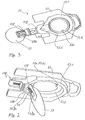
- Fig. 1 shows a dust filter bag 1 for use in a vacuum cleaner.
- the dust filter bag 1 comprises a bag 11 having a bag inlet opening 11 e and a holding plate 12 arranged on the outside of the bag 11 so that the central opening of the holding plate 12 is aligned with the bag inlet opening 11 e.
- a sealing ring 12d is formed to form an annular sealing lip.
- a closure flap 13 is articulated. The closure flap 13 is acted upon by a spring 14 in the closed position. In the closed position, the closure flap 13 rests on the annular sealing lip 12d.
- the bag 11 is made of an air-permeable filter material, preferably non-woven material, whose pore width is dimensioned such that the dust contained in the sucked-in air flow is retained in the bag 11.
- the retaining plate 12 is formed of preferably thermoplastic material.
- the sealing ring 12d is formed of an elastomer, such as rubber.
- the one in the illustration in Fig. 1 in a plane in front of the holding plate 12 arranged bag 11 is in Fig. 1 Deviating from the usual representation rules shown with a dashed thin line.
- the holding plate 12 shown in plan view from the interior of the bag 11 forth is drawn with solid lines.
- the bag 11 is welded to the opening edge of the bag inlet opening 11 e on the side facing the bag interior side of the holding plate 12, on a formed on this side of the holding plate 12 raised ring edge 12 r, which surrounds the central opening of the holding plate 12.
- the annular sealing lip 12d is formed in the central opening of the holding plate 12.
- the inner edge 12di of the annular sealing lip 12d forms the inlet opening 12e of the holding plate 12.
- FIG. 3 shows, the closure flap 13 with a holding plate side Closure flap holder 12h connected via a film hinge 13f.
- the closure flap 13 is pivotable from the closed position to the open position and vice versa.
- a pipe socket can engage the inlet opening 12e, 11e in the dust filter bag 1 inserted in the vacuum cleaner, so that the closure flap 13 is pivoted into its open position into the bag due to this engagement.
- the closing flap 13 can be pivoted into the bag 11 due to the suction pressure in its open position.
- the spring is designed as a helical spring 14.
- the holding plate 12 has, in the holding plate-side closure flap holder 12h, a retaining plate 12fa on the holding plate side, in which a first longitudinal section of the helical spring 14 supported therein is accommodated.
- the holding plate-side spring receiving 12fa is formed in the illustrated embodiment as a channel which is at least partially formed as a bore or a groove.
- the closure flap 13 has a closure flap-side spring receptacle 13fa, in which the second longitudinal section of the coil spring 14 which is supported on the closure flap 13 is included.
- the closure plate-side spring receptacle 13fa is formed as a channel which is at least partially formed as a bore or a groove.
- the spring receptacles 12fa, 13fa are arranged relative to one another such that the longitudinal axes of the receptacles are arranged perpendicular to the pivot axis of the first film hinge 13f.
- the end portion of the coil spring 14 disposed in the holder plate side spring receiver 12fa is fixed in the spring receiver 12fa.
- the arranged in the closure flap side spring receiving 13fa end portion of the coil spring 14 is axially displaceable in the spring receptacle 13fa. When pivoting the closure flap 13, this end portion of the spring in the spring seat 13fa is axially displaced.
- the coil spring 14 When pivoting the closure flap 13, the coil spring 14 is loaded about a bending axis 14 b, which is arranged according to the invention at an angle to the longitudinal axis of the coil spring 14.
- the longitudinal axis of the coil spring 14 is perpendicular to the pivot axis of the film hinge 13f and the bending axis 14b is aligned with the pivot axis of this film hinge 13f or is slightly offset parallel to the pivot axis of the film hinge 13f.
- This offset can be formed by appropriate arrangement and design of the spring 14 and its receptacles 12fa, 13fa to the interior of the bag 11 towards or in the opposite direction, ie in the direction of the interior of the bag 11 away.
- the coil spring 14 is formed as a prestressed tension spring.
- the coil spring 14 is designed such that the bending radius of the coil spring corresponds approximately to three times the diameter of the coil spring. In order to allow the coil spring 14 in the open position sufficient extent and to avoid a collision of the bending radius with the closure flap 13, the configuration of the groove is based on this specification.
- Fig. 4 shows a spring characteristic K1 of the coil spring 14 according to the invention in comparison to a spring characteristic K2 a known leaf spring, for example according to EP 1 849 392 A1 ,
- the spring force F over the spring travel s shown.
- the spring travel s is in each case proportional to the bending angle of the spring.
- the spring characteristic K2 of the leaf spring the spring characteristic of the leaf spring on a strong linear force increase, which then goes into a degressive course.
- the spring characteristic K1 of the helical spring 14 the spring characteristic of the helical spring extends degressively from the beginning.
- the characteristic curves K1 in Fig. 4 applies to a non-preloaded coil spring.
- the coil spring 14 is in the in the FIGS. 1 to 3 illustrated embodiment, however, designed as a prestressed tension spring.
- the bias is further adjustable by providing the spring with a pre-bend to be adjusted.
- the angle of the pre-bend can be advantageously set in the range of 5 ° to 30 ° so as to set a predetermined closing force of the shutter 13 in the closed position.
- the adjustment of the preload can be made by forming the angular position of the spring retainer in the support plate 12 and / or the angular position of the spring retainer in the closure flap 13. It depends on the relative angular position of the two spring retainers in the closed position of the flap.
- the bias affects the characteristic of the spring. By biasing a particularly strong degressive course is formed. Since the windings of the prestressed tension spring lie on one another with a certain preload, the force for releasing the preload must first be overcome. If this bias is overcome, the increase in force is slow and approaches a horizontal.
- Fig. 3 shows the holding plate 12 with the closure flap 13 as a one-piece injection molded part 15.
- the injection molded part 15 is formed of a thermoplastic material.
- the one-piece injection molded part 15 is in three parts. It consists of the three parts: the shutter 13, the shutter holder 12h and the holding plate 12. The three parts are connected via two film hinges 13f, 15f.
- the first film hinge 13f is formed between the shutter 13 and the shutter holder 12h.
- the second film hinge 15f is formed between the holding plate 12 and the shutter holder 12h.
- the closure flap holder 12h connected to the closure flap 13 is rotated 180 ° about the pivot axis of the second Film hinge 15f pivoted, ie folded, so that the shutter holder 12h reaches the end position in which the shutter holder 12h rests on the support plate 12 and the shutter 13 comes into the closed position.
- the coil spring 14 can be mounted, that is, inserted into the spring receptacles 12fa, 13fa described above. But it is also possible to insert the coil spring 14 already in the injection molding apparatus, so that the coil spring 14 is integrated into the injection molded part 15.
Landscapes
- Engineering & Computer Science (AREA)
- Mechanical Engineering (AREA)
- Filters For Electric Vacuum Cleaners (AREA)
Abstract
Description
- Die Erfindung betrifft einen Staubfilterbeutel nach dem Oberbegriff des Anspruchs 1 sowie ein Verfahren zur Herstellung eines Staubfilterbeutels.
- In der
DE 44 153 50 A1 wird ein Staubfilterbeutel mit einer Halteplatte beschrieben, bei der die Halteplatte mit einer Verschlussklappe ausgebildet ist, die über ein bandartiges Federelement verfügt, das die Verschlussklappe in einer die Öffnung des Staubfilterbeutels verschließenden Position hält. - Entsprechend der Federkennlinie des bandförmigen Federelements steigt die Federkraft proportional zum Öffnungswinkel der Verschlussklappe an. Da sich die Verschlussklappe bei in das Staubsauggerät eingesetztem Staubfilterbeutel in der Offenstellung befindet, treten große Kräfte auf, die in der Lagerung des Federelements plastische Verformungen bewirken. Demzufolge schließt die Verschlussklappe bei Entnahme des Staubfilterbeutels aus dem Staubsauggerät nicht mehr vollständig.
- In der
DE 19 948 909 A1 wird eine Halteplatte mit Verschlussklappe für einen Staubfilterbeutel beschrieben, wobei die Verschlussklappe über eine Blattfeder in einer Verschlussstellung gehalten wird. Die Blattfeder weist eine Bombierung auf, d. h. sie ist mit einer Wölbung ausgebildet, die unter einem Winkel von 90° zur Längsachse erstreckt ist. Zum Öffnen der Verschlussklappe muss eine relativ hohe Kraft aufgebracht werden. Um die Gegenkraft beim Öffnen aufnehmen zu können, muss die Halteplatte sehr stabil ausgebildet sein, um eine Durchbiegung der Halteplatte beim Öffnen der Verschlussklappe zu verhindern. - In der
EP 1 849 392 A1 wird eine Halteplatte mit einer Verschlussklappe beschrieben, bei der eine Bandfeder in der Verschlussstellung stark vorgespannt ist. Um die Kraft beim Öffnen der Verschlussklappe nicht zu stark ansteigen zu lassen, wird der Biegewinkel der Bandfeder dadurch begrenzt, dass das Ende der Bandfeder bei einem bestimmten Öffnungswinkel der Verschlussklappe in eine Vertiefung eintaucht, sodass eine weitere Erhöhung der Biegekraft vermieden wird. Dieser Aufbau ist relativ aufwendig, auch muss die Bandfeder stark vorgespannt werden, wobei durch plastische Verformungen im Bereich der Krafteinleitung der Federkräfte in die Halteplatte die Vorspannung, soweit reduziert wird, dass ein sicheres Verschließen der Verschlussklappe nicht mehr gewährleistet wird. - In der
DE202013100862 U1 wird eine Halteplatte mit einer Verschlussklappe beschrieben, bei der verschiedene Varianten von Federelementen Verwendung finden. Allen gemeinsam ist, dass die Biegeachse des Federelements winklig zur Drehachse der Verschlussklappe ausgerichtet ist. Neben Blattfedern und Stabfedern sind auch sogenannte Schenkelfedern vorgesehen. Allen beschriebenen Varianten ist gemeinsam, dass sie relativ aufwendig zu fertigen sind. - Aufgabe der vorliegenden Erfindung ist es, einen Staubfilterbeutel anzugeben, der zumindest einen Teil der genannten Nachteile vermeidet und kostengünstig herstellbar ist.
- Erfindungsgemäß wird diese Aufgabe mit dem Gegenstand des Anspruchs 1 gelöst. Bei dieser Lösung handelt es sich um einen Staubfilterbeutel zum Einsatz in einem Staubsauggerät. Der Staubfilterbeutel umfasst:
- einen Beutel aus Filtermaterial mit einer Beuteleinlassöffnung;
- eine Halteplatte mit einer Halteplatteneinlassöffnung;
- eine Verschlussklappe, die an der Halteplatte über ein Scharnier um eine Scharnierachse derart schwenkbar gelagert ist, dass die Verschlussklappe in einer Geschlossenstellung die Halteplatteneinlassöffnung verschließt und in einer Offenstellung die Halteplatteneinlassöffnung freigibt;
- wobei die Halteplatte im Bereich der Beuteleinlassöffnung auf der Außenseite des Beutels derart angeordnet ist, dass die Beuteleinlassöffnung mit der Halteplatteneinlassöffnung fluchtet;
- wobei die Verschlussklappe durch eine Feder in die Geschlossenstellung beaufschlagt ist, indem die Feder mit einem ersten Ende an der Verschlussklappe und mit einem zweiten Ende an der Halteplatte abgestützt ist.
- Wesentlich bei der erfindungsgemäßen Lösung ist, dass die Feder als eine Schraubenfeder ausgebildet ist und dass die Schraubenfeder mit einer koaxial zu den Schraubenwindungen der Schraubenfeder verlaufenden Längsachse ausgebildet ist.
- Die Schraubenfeder weist in ihrer Erstreckung entlang der Längsachse einen ersten Längsabschnitt auf, der an der Halteplatte abgestützt ist und sie weist einen zweiten Längsabschnitt auf, der an der Verschlussklappe abgestützt ist.
- Die Abstützung und Anordnung der Schraubenfeder ist derart ausgebildet, dass beim Verschwenken der Verschlussklappe die Schraubenfeder um eine Biegeachse belastet wird, die winkelig, vorzugsweise in einem rechten Winkel zur Längsachse der Schraubenfeder angeordnet ist.
- Der vorgeschlagene Staubfilterbeutel kann den Vorteil aufweisen, dass die Federkennlinie der um ihre Biegeachse belasteten Schraubenfeder, die winkelig zur Längsachse der Schraubenfeder angeordnet ist, einen degressiven Kraftverlauf aufweist. Der degressive Kraftverlauf der Schraubenfeder reduziert die Kräfte auf das Verschlussklappensystem in der Offenstellung der Verschlussklappe. Auf diese Weise können plastische Verformungen, die sich negativ auf die Schließkraft in der Geschlossenstellung der Verschlussklappe auswirken, vermieden werden.
- Bei vorteilhaften Ausführungen kann vorgesehen sein, dass die Biegeachse der Schraubenfeder beim Verschwenken der Verschlussklappe mit der Scharnierachse in einer gemeinsamen Linie fluchtend angeordnet ist oder bei alternativen Ausführungen, dass die Biegeachse der Schraubenfeder beim Verschwenken der Verschlussklappe zu der Scharnierachse parallel versetzt angeordnet ist.
- Zur Einstellung der Kennlinie der Feder kann vorgesehen sein, dass die Biegeachse relativ zur Scharnierachse in Richtung der Flächenerstreckung der Halteplatte und/oder der Verschlussklappe lateral versetzt angeordnet ist. Alternativ oder zusätzlich kann vorgesehen sein, dass die Biegeachse relativ zur Scharnierachse in einer Richtung senkrecht zur Flächenerstreckung der Halteplatte und/oder der Verschlussklappe angeordnet ist.
- Bei besonderen Ausführungen kann auch vorgesehen sein, dass die Biegeachse parallel versetzt in einer gemeinsamen Ebene mit der Scharnierachse angeordnet ist, wobei die gemeinsame Ebene senkrecht zur Flächenerstreckung der Halteplatte und/oder der Verschlussklappe angeordnet ist.
- Eine besonders vorteilhafte Kennlinie wird erhalten, wenn vorgesehen ist, dass die Schraubenfeder als Zugfeder oder als Druckfeder ausgebildet ist. Eine Optimierung der Kennlinie kann erhalten werden, wenn vorgesehen ist, dass die Schraubenfeder in der Geschlossenstellung der Verschlussklappe als vorgespannte Zugfeder oder als vorgespannte Druckfeder ausgebildet ist. Es kann auch vorgesehen sein, dass die Schraubenfeder in der Geschlossenstellung der Verschlussklappe mit nicht linearer Längsachse, vorzugsweise um die Biegeachse gebogener Längsachse angeordnet ist.
- Weiter kann vorgesehen sein, dass die Halteplatte eine halteplattenseitige Aufnahme aufweist, in und/oder an und/oder auf der der an der Halteplatte abgestützte erste Längsabschnitt der Schraubenfeder aufgenommen ist.
- In einer vorteilhaften Ausbildung kann vorgesehen sein, dass die halteplattenseitige Aufnahme als Kanal ausgebildet ist, der zumindest abschnittsweise als Bohrung oder als Nut ausgebildet ist.
- Die halteplattenseitige Aufnahme kann länglich ausgebildet sein mit einer Längserstreckung, die in einem spitzen Winkel zur Flächenerstreckung der Halteplatte angeordnet ist.
- Es kann vorgesehen sein, dass die Verschlussklappe eine verschlussklappenseitige Aufnahme aufweist, in und/oder an und/oder auf der der an der Verschlussklappe abgestützte zweite Längsabschnitt der Schraubenfeder aufgenommen ist.
- Die verschlussklappenseitige Aufnahme kann als Kanal ausgebildet sein, der zumindest abschnittsweise als Bohrung oder als Nut ausgebildet ist.
- Es kann auch vorgesehen sein, dass die verschlussklappenseitige Aufnahme länglich ausgebildet ist mit einer Längserstreckung, die in einem spitzen Winkel zur Flächenerstreckung der Verschlussklappe angeordnet ist.
- Es kann vorgesehen sein, dass die Schraubenfeder mit dem ersten Längsabschnitt an der Halteplatte axial festgelegt gelagert ist und mit dem zweiten Längsabschnitt an der Verschlussklappe axial verschiebbar gelagert ist oder dass die Schraubenfeder mit dem ersten Längsabschnitt an der Halteplatte axial verschiebbar gelagert ist und mit dem zweiten Längsabschnitt an der Verschlussklappe axial festgelegt gelagert ist.
- In einer alternativen Ausführung kann vorgesehen sein, dass die Schraubenfeder mit dem ersten Längsabschnitt an der Halteplatte axial festgelegt gelagert ist und mit dem zweiten Längsabschnitt an der Verschlussklappe axial festgelegt gelagert ist, oder dass die Schraubenfeder mit dem ersten Längsabschnitt an der Halteplatte axial verschiebbar gelagert ist und mit dem zweiten Längsabschnitt an der Verschlussklappe axial verschiebbar gelagert ist.
- Die Schraubenfeder kann als vorgespannte Zugfeder oder als Druckfeder ausgebildet sein.
- In einer vorteilhaften Ausführung kann vorgesehen sein, dass die Halteplatte mit der Verschlussklappe als einstückiges Kunststoffspritzgussteil, vorzugsweise aus einem Thermoplast, ausgebildet ist und das Scharnier als Filmscharnier ausgebildet ist. Das Filmscharnier ist ein Abschnitt des Kunststoffspritzgussteils, der eine mit einem Film oder einer Folie vergleichbare geringe Dicke aufweist und daher biegbar ausgebildet ist. Unter dem Begriff Filmscharnier wird ein Abschnitt eines Kunststoffteils, vorzugsweise eines Spritzgussteils verstanden, der eine mit einem Film oder einer Folie vergleichbare geringe Dicke aufweist und daher biegbar ausgebildet ist.
- Es kann vorgesehen sein, dass die Halteplatte einen Verbindungsabschnitt aufweist, der mit der Verschlussklappe über das Filmscharnier verbunden ist und über ein zweites Filmscharnier mit einem Hauptabschnitt der Halteplatte verbunden ist, der die Halteplatteneinlassöffnung aufweist.
- Weiter kann vorgesehen sein, dass an der Halteplatte eine kreisringförmige Dichtplatte aus einem gummielastischen Werkstoff angeordnet ist, an der die Verschlussklappe in der Geschlossenstellung dichtend anliegt.
- Die eingangs genannte Aufgabe wird ferner erfindungsgemäß bereits durch eine Halteplatte gelöst, die ausgebildet ist, wie sie für den vorgeschlagenen Staubfilterbeutel erläutert ist. Bei dieser Lösung handelt es sich also um eine Halteplatte für einen Staubfilterbeutel zum Einsatz in einem Staubsauggerät. Wesentlich bei dieser Halteplatte ist, dass die Halteplatte so ausgebildet ist, wie die Halteplatte eines vorangehend als erfindungsgemäß beschriebenen Staubfilterbeutels.
- Als ein bevorzugtes Verfahren zur Herstellung des vorgeschlagenen Staubfilterbeutels kann vorgesehen sein, dass die Halteplatte mit der Verschlussklappe aus einem vorzugsweise thermoplastischen Kunststoffmaterial über Spritzgießen als einstückiges Spritzgussteil in einem Spritzgusswerkzeug hergestellt wird, wobei die Schraubenfeder vor dem Spritzgussvorgang in das Spritzgusswerkzeug eingelegt wird und beim Spritzgießen teilweise mit dem thermoplastischen Kunststoffmaterial der Halteplatte und/oder der Verschlussklappe verbunden wird oder die Schraubenfeder nach dem Spritzgussvorgang in die Halteplatte und/oder in die Verschlussklappe eingelegt wird.
- Es kann vorgesehen sein, dass die Dichtplatte beim Spritzgießen teilweise mit dem thermoplastischen Kunststoffmaterial der Halteplatte verbunden wird, vorzugsweise im 2K-Verfahren, oder nach dem Spritzgießen mit der Halteplatte verklebt wird.
- Die Erfindung wird nun anhand von Ausführungsbeispielen näher erläutert. Es zeigen
- Fig. 1
- ein Ausführungsbeispiel des erfindungsgemäßen Staubfilterbeutels mit einer durch eine Verschlussklappe verschließbaren Halteplatte in der Draufsicht vom Innenraum des Beutels her;
- Fig. 2
- die Halteplatte in
Fig. 1 mit Verschlussklappe in Offenstellung als Einzelteil in perspektivischer Ansicht; - Fig. 3
- die Halteplatte mit der Verschlussklappe gemäß
Fig. 2 , jedoch als einteiliges Spritzgussteil vor der Montage; - Fig. 4
- eine Federkennlinie einer Schraubenfeder der Halteplatte in
Fig. 1 im Vergleich zu einer Federkennlinie einer Blattfeder. -
Fig. 1 zeigt einen Staubfilterbeutel 1 zum Einsatz in einem Staubsauggerät. Der Staubfilterbeutel 1 umfasst einen Beutel 11 mit einer Beuteleinlassöffnung 11 e und eine auf der Außenseite des Beutels 11 derart angeordnete Halteplatte 12, dass die zentrale Öffnung der Halteplatte 12 mit der Beuteleinlassöffnung 11e fluchtet. In der Öffnung der Halteplatte 12 ist ein Dichtungsring 12d unter Ausbildung einer ringförmigen Dichtungslippe angeformt. An der Halteplatte 12 ist eine Verschlussklappe 13 gelenkig gelagert. Die Verschlussklappe 13 wird durch eine Feder 14 in die Geschlossenstellung beaufschlagt. In der Geschlossenstellung liegt die Verschlussklappe 13 auf der ringförmigen Dichtungslippe 12d auf. Der Beutel 11 ist aus einem luftdurchlässigen Filtermaterial, vorzugsweise Vliesmaterial, ausgebildet, dessen Porenweite so bemessen ist, dass der in dem eingesaugten Luftstrom enthaltene Staub in dem Beutel 11 zurückgehalten wird. Die Halteplatte 12 ist aus vorzugsweise thermoplastischem Kunststoffmaterial ausgebildet. Der Dichtungsring 12d ist aus einem Elastomer ausgebildet, beispielsweise aus Gummi. - Der in der Darstellung in
Fig. 1 in einer Ebene vor der Halteplatte 12 angeordnete Beutel 11 ist inFig. 1 abweichend von den üblichen Darstellungsregeln mit einer gestrichelten dünnen Linie dargestellt. Die in der Draufsicht vom Innenraum des Beutels 11 her dargestellte Halteplatte 12 ist mit Volllinien gezeichnet. Der Beutel 11 ist mit dem Öffnungsrand der Beuteleinlassöffnung 11 e auf der zum Beutelinnenraum gewandten Seite der Halteplatte 12 verschweißt, und zwar auf einem auf dieser Seite der Halteplatte 12 ausgebildeten erhabenen Ringrand 12r, der die zentrale Öffnung der Halteplatte 12 umgibt. In der zentralen Öffnung der Halteplatte 12 ist die ringförmige Dichtungslippe 12d ausgebildet. Der Innenrand 12di der ringförmigen Dichtungslippe 12d bildet die Einlassöffnung 12e der Halteplatte 12. WieFigur 3 zeigt, ist die Verschlussklappe 13 mit einem halteplattenseitigen Verschlussklappenhalter 12h über ein Filmscharnier 13f verbunden. Um die Schwenkachse des Filmscharniers 13f ist die Verschlussklappe 13 von der Geschlossenstellung in die Offenstellung und umgekehrt schwenkbar. Wenn der Staubfilterbeutel 1 in das Staubsauggerät eingesetzt ist, ist im Saugbetrieb die Verschlussklappe 13 in Offenstellung (sieheFig. 2 ), so dass im Betrieb des Staubsauggerätes ein angesaugter staubbelasteter Luftstrom über die Halteplatteneinlassöffnung 12e und die Beuteleinlassöffnung 11 e in den Beutel 11 eintreten kann. - Je nach Staubsaugertyp kann in den im Staubsauger eingesetzten Staubfilterbeutel 1 ein Rohrstutzen in die Einlassöffnung 12e, 11 e eingreifen, sodass aufgrund dieses Eingriffs die Verschlussklappe 13 in ihre Offenstellung in den Beutel hineingeschwenkt ist. Bei Staubsaugertypen, bei denen kein in den Staubfilterbeutel eingreifender Rohrstutzen vorhanden ist, kann die Verschlussklappe 13 aufgrund des Saugdrucks in ihre Offenstellung in den Beutel 11 hineingeschwenkt sein.
- Was die Ausgestaltung und Anordnung der die Verschlussklappe 13 in die Geschlossenstellung beaufschlagenden Feder 14 betrifft: Bei dem dargestellten Ausführungsbeispiel ist die Feder als Schraubenfeder 14 ausgebildet. Die Halteplatte 12 weist in dem halteplattenseitigem Verschlussklappenhalter 12h eine halteplattenseitige Federaufnahme 12fa auf, in der ein darin abgestützter erster Längsabschnitt der Schraubenfeder 14 aufgenommen ist. Die halteplattenseitige Federaufnahme 12fa ist in dem dargestellten Ausführungsbeispiel als Kanal ausgebildet, der zumindest abschnittsweise als Bohrung oder als Nut ausgebildet ist. Die Verschlussklappe 13 weist eine verschlussklappenseitige Federaufnahme 13fa auf, in der der an der Verschlussklappe 13 abgestützte zweite Längsabschnitt der Schraubenfeder 14 aufgenommen ist. Die verschlussplattenseitige Federaufnahme 13fa ist als Kanal ausgebildet, der zumindest abschnittsweise als Bohrung oder als Nut ausgebildet ist.
- Die Federaufnahmen 12fa, 13fa sind so zueinander angeordnet, dass die Längsachsen der Aufnahmen senkrecht zu der Schwenkachse des ersten Filmscharniers 13f angeordnet sind. Der in der halteplattenseitigen Federaufnahme 12fa angeordnete Endabschnitt der Schraubenfeder 14 ist in der Federaufnahme 12fa fixiert. Der in der verschlussklappenseitigen Federaufnahme 13fa angeordnete Endabschnitt der Schraubenfeder 14 ist in der Federaufnahme 13fa axial verschiebbar. Beim Verschwenken der Verschlussklappe 13 wird dieser Endabschnitt der Feder in der Federaufnahme 13fa axial verschoben.
- Beim Verschwenken der Verschlussklappe 13 wird die Schraubenfeder 14 um eine Biegeachse 14b belastet, die erfindungsgemäß winkelig zur Längsachse der Schraubenfeder 14 angeordnet ist. In dem dargestellten Fall ist die Längsachse der Schraubenfeder 14 rechtwinkelig zur Schwenkachse des Filmscharniers 13f und die Biegeachse 14b fluchtet mit der Schwenkachse dieses Filmscharniers 13f oder ist parallel zur Schwenkachse des Filmscharniers 13f geringfügig versetzt. Dieser Versatz kann durch entsprechende Anordnung und Ausgestaltung der Feder 14 und deren Aufnahmen 12fa, 13fa zum Innenraum des Beutels 11 hin oder in die Gegenrichtung, d.h. in Richtung vom Innenraum des Beutels 11 weg ausgebildet sein.
- Bei dem dargestellten Ausführungsbeispiel ist die Schraubenfeder 14 als vorgespannte Zugfeder ausgebildet.
- Die Schraubenfeder 14 ist derart ausgestaltet, dass der Biegeradius der Schraubenfeder ca. dem dreifachen Durchmesser der Schraubenfeder entspricht. Um der Schraubenfeder 14 in Offenstellung genügend Ausdehnung zu erlauben und eine Kollision des Biegeradius mit der Verschlussklappe 13 zu vermeiden, orientiert sich die Ausgestaltung der Nut an dieser Vorgabe.
-
Fig. 4 zeigt eine Federkennlinie K1 der erfindungsgemäßen Schraubenfeder 14 im Vergleich zu einer Federkennlinie K2 einer bekannten Blattfeder, z.B. gemäßEP 1 849 392 A1 . Hierbei ist inFig. 4 die Federkraft F über dem Federweg s dargestellt. Der Federweg s ist jeweils proportional zu dem Biegewinkel der Feder. Wie aus der Federkennlinie K2 der Blattfeder zu erkennen ist, weist die Federkennlinie der Blattfeder einen starken linearen Kraftanstieg auf, der dann in einen degressiven Verlauf übergeht. Wie aus der Federkennlinie K1 der Schraubenfeder 14 zu erkennen ist, verläuft die Federkennlinie der Schraubenfeder von Anfang an degressiv. - Die Kennlinien K1 in
Fig. 4 gilt für eine nicht vorgespannte Schraubenfeder. Die Schraubenfeder 14 ist in dem in denFiguren 1 bis 3 dargestellten Ausführungsbeispiel jedoch als vorgespannte Zugfeder ausgebildet. Die Vorspannung ist weiterhin einstellbar, indem die Feder mit einer einzustellenden Vorbiegung versehen wird. Bei der Schraubenfeder 14 kann der Winkel der Vorbiegung vorteilhafterweise im Bereich von 5° bis 30° eingestellt werden, um so eine vorbestimmte Schließkraft der Verschlussklappe 13 in der Geschlossenstellung einzustellen. Die Einstellung der Vorspannung kann durch die Ausbildung der Winkelstellung der Federaufnahme in der Halteplatte 12 und/oder der Winkelstellung der Federaufnahme in der Verschlussklappe 13 vorgenommen werden. Hierbei kommt es auf die relative Winkelstellung der beiden Federaufnahmen in der Geschlossenstellung der Verschlussklappe an. - Die Vorspannung beeinflusst die Kennlinie der Feder. Durch die Vorspannung wird ein besonders starker degressiver Verlauf ausgebildet. Da die Windungen der vorgespannten Zugfeder mit einer gewissen Vorspannung aufeinander liegen, muss erst die Kraft zum Lösen der Vorspannung überwunden werden. Ist diese Vorspannung überwunden, erfolgt der Kraftanstieg nur noch langsam und nähert sich einer Horizontalen.
-
Fig. 3 zeigt die Halteplatte 12 mit der Verschlussklappe 13 als einstückiges Spritzgussteil 15. Das Spritzgussteil 15 ist aus einem thermoplastischen Kunststoff ausgebildet. - Das einstückige Spritzgussteil 15 ist dreiteilig. Es besteht aus den drei Teilen: die Verschlussklappe 13, der Verschlussklappenhalter 12h und die Halteplatte 12. Die drei Teile sind über zwei Filmscharniere 13f, 15f verbunden.
- Das erste Filmscharnier 13f ist zwischen der Verschlussklappe 13 und dem Verschlussklappenhalter 12h ausgebildet. Das zweite Filmscharnier 15f ist zwischen der Halteplatte 12 und dem Verschlussklappenhalter 12h ausgebildet.
- Bei der Montage wird der mit der Verschlussklappe 13 verbundene Verschlussklappenhalter 12h um 180° um die Schwenkachse des zweiten Filmscharniers 15f geschwenkt, d.h. umgeklappt, so dass der Verschlussklappenhalter 12h in die Endposition gelangt, in der der Verschlussklappenhalter 12h auf der Halteplatte 12 aufliegt und die Verschlussklappe 13 in die Geschlossenstellung gelangt. Vor diesem Umklappen im Rahmen der Montage kann die Schraubenfeder 14 montiert werden, d. h. in die weiter oben beschriebenen Federaufnahmen 12fa, 13fa eingelegt werden. Es ist aber auch möglich, die Schraubenfeder 14 bereits in die Spritzgussvorrichtung einzulegen, so dass die Schraubenfeder 14 in das Spritzgussteil 15 integriert ist.
-
- 1
- Staubfilterbeutel
- 11
- Beutel
- 11e
- Beuteleinlassöffnung
- 12
- Halteplatte
- 12d
- Dichtungsring
- 12di
- Innenrand von 12d
- 12fa
- Federaufnahme
- 12h
- Halteplatte für Verschlussklappenhalter
- 12r
- vorspringender ringförmiger Rand
- 12e
- Halteplatteneinlassöffnung
- 13
- Verschlussklappe
- 13fa
- Federaufnahme
- 13f
- erstes Filmscharnier
- 13h
- Verschlussklappenhalter
- 14
- Schraubenfeder
- 14b
- Biegeachse der Schraubenfeder
- 15
- Spritzgussteil
- 15f
- zweites Filmscharnier
- K1, K2
- Federkennlinien
- F
- Federkraft
- s
- Federweg
Claims (19)
- Staubfilterbeutel (1) zum Einsatz in einem Staubsauggerät, umfassend- einen Beutel (11) aus Filtermaterial mit einer Beuteleinlassöffnung (11e);- eine Halteplatte (12) mit einer Halteplatteneinlassöffnung (12e);- eine Verschlussklappe (13), die an der Halteplatte (12) über ein Scharnier (13f) um eine Scharnierachse derart schwenkbar gelagert ist, dass die Verschlussklappe (13) in einer Geschlossenstellung die Halteplatteneinlassöffnung (12e) verschließt und in einer Offenstellung die Halteplatteneinlassöffnung (12e) freigibt;- wobei die Halteplatte (12) im Bereich der Beuteleinlassöffnung (11 e) auf der Außenseite des Beutels (11) derart angeordnet ist, dass die Beuteleinlassöffnung (11 e) mit der Halteplatteneinlassöffnung (12e) fluchtet;- wobei die Verschlussklappe (13) durch eine Feder (14) in die Geschlossenstellung beaufschlagt ist, indem die Feder mit einem ersten Ende an der Verschlussklappe (13) und mit einem zweiten Ende an der Halteplatte (12) abgestützt ist,dadurch gekennzeichnet,
dass die Feder als eine Schraubenfeder (14) mit einer koaxial zu den Schraubenwindungen der Schraubenfeder (14) verlaufenden Längsachse ausgebildet ist,
wobei die Schraubenfeder (14) in ihrer Erstreckung entlang der Längsachse einen ersten Längsabschnitt aufweist, der an der Halteplatte (12) abgestützt ist und einen zweiten Längsabschnitt aufweist, der an der Verschlussklappe (13) abgestützt ist,
wobei die Abstützung und Anordnung der Schraubenfeder (14) derart ausgebildet ist, dass beim Verschwenken der Verschlussklappe (13) die Schraubenfeder (14) um eine Biegeachse (14b) belastet wird, die winkelig zur Längsachse der Schraubenfeder (14) angeordnet ist. - Staubfilterbeutel nach Anspruch 1,
dadurch gekennzeichnet,
dass die Biegeachse (14b) der Schraubenfeder (14) beim Verschwenken der Verschlussklappe (13) mit der Scharnierachse in einer gemeinsamen Linie fluchtend oder zu der Scharnierachse parallel versetzt angeordnet ist. - Staubfilterbeutel nach einem der vorangehenden Ansprüche,
dadurch gekennzeichnet,
dass die Biegeachse (14b) relativ zur Scharnierachse in Richtung der Flächenerstreckung der Halteplatte (12) und/oder der Verschlussklappe (13) lateral versetzt angeordnet ist. - Staubfilterbeutel nach einem der vorangehenden Ansprüche,
dadurch gekennzeichnet,
dass die Biegeachse (14b) relativ zur Scharnierachse in einer Richtung senkrecht zur Flächenerstreckung der Halteplatte (12) und/oder der Verschlussklappe (13) angeordnet ist. - Staubfilterbeutel nach einem der vorangehenden Ansprüche,
dadurch gekennzeichnet,
dass die Biegeachse (14b) parallel versetzt in einer gemeinsamen Ebene mit der Scharnierachse angeordnet ist, wobei die gemeinsame Ebene senkrecht zur Flächenerstreckung der Halteplatte (12) und/oder der Verschlussklappe (13) angeordnet ist. - Staubfilterbeutel nach einem der vorangehenden Ansprüche,
dadurch gekennzeichnet,
dass die Schraubenfeder (14) als Zugfeder oder als Druckfeder ausgebildet ist. - Staubfilterbeutel nach Anspruch 6,
dadurch gekennzeichnet,
dass die Schraubenfeder (14) in der Geschlossenstellung der Verschlussklappe als vorgespannte Zugfeder oder als vorgespannte Druckfeder ausgebildet ist. - Staubfilterbeutel nach einem der Ansprüche 6 oder 7,
dadurch gekennzeichnet,
dass die Schraubenfeder (14) in der Geschlossenstellung der Verschlussklappe mit nicht linearer Längsachse, vorzugsweise um die Biegeachse (14b) gebogener Längsachse angeordnet ist. - Staubfilterbeutel nach einem der vorangehenden Ansprüche,
dadurch gekennzeichnet,
dass die Halteplatte (12) eine halteplattenseitige Federaufnahme (12fa) aufweist, in und/oder an und/oder auf der der an der Halteplatte (12) abgestützte erste Längsabschnitt der Schraubenfeder (14) aufgenommen ist, und/oder
dass die Verschlussklappe (13) eine verschlussklappenseitige Federaufnahme (13fa) aufweist, in und/oder an und/oder auf der der an der Verschlussklappe (13) abgestützte zweite Längsabschnitt der Schraubenfeder (14) aufgenommen ist. - Staubfilterbeutel nach einem der vorangehenden Ansprüche,
dadurch gekennzeichnet,
dass die halteplattenseitige Federaufnahme (12fa) als Kanal ausgebildet ist, der zumindest abschnittsweise als Bohrung oder als Nut ausgebildet ist, und/oder
dass die verschlussklappenseitige Federaufnahme (13fa) als Kanal ausgebildet ist, der zumindest abschnittsweise als Bohrung oder als Nut ausgebildet ist. - Staubfilterbeutel nach einem der vorangehenden Ansprüche,
dadurch gekennzeichnet,
dass die halteplattenseitige Federaufnahme (12fa) länglich ausgebildet ist mit einer Längserstreckung, die in einem spitzen Winkel zur Flächenerstreckung der Halteplatte (12) angeordnet ist, und/oder dass die verschlussklappenseitige Federaufnahme (13fa) länglich ausgebildet ist mit einer Längserstreckung, die in einem spitzen Winkel zur Flächenerstreckung der Verschlussklappe (13) angeordnet ist. - Staubfilterbeutel nach einem der vorangehenden Ansprüche,
dadurch gekennzeichnet,
dass die Schraubenfeder (14) mit dem ersten Längsabschnitt halteplattenseitig axial festgelegt gelagert ist und mit dem zweiten Längsabschnitt verschlussklappenseitig axial verschiebbar gelagert ist oder,
dass die Schraubenfeder (14) mit dem ersten Längsabschnitt halteplattenseitig axial verschiebbar gelagert ist und mit dem zweiten Längsabschnitt verschlussklappenseitig axial festgelegt gelagert ist. - Staubfilterbeutel nach einem der Ansprüche 1 bis 11,
dadurch gekennzeichnet,
dass die Schraubenfeder (14) mit dem ersten Längsabschnitt halteplattenseitig axial festgelegt gelagert ist und mit dem zweiten Längsabschnitt verschlussklappenseitig axial festgelegt gelagert ist, oder
dass die Schraubenfeder (14) mit dem ersten Längsabschnitt halteplattenseitig axial verschiebbar gelagert ist und mit dem zweiten Längsabschnitt verschlussklappenseitig axial verschiebbar gelagert ist. - Staubfilterbeutel nach einem der vorangehenden Ansprüche,
dadurch gekennzeichnet,
dass die Halteplatte (12) mit der Verschlussklappe (13) als einstückiges Kunststoffspritzgussteil, vorzugsweise aus einem Thermoplast, ausgebildet ist und das Scharnier als Filmscharnier (13f) ausgebildet ist. - Staubfilterbeutel nach Anspruch 14,
dadurch gekennzeichnet,
dass die Halteplatte (12) einen Verbindungsabschnitt (12h) aufweist, der mit der Verschlussklappe (13) über das Filmscharnier verbunden ist und über ein zweites Filmscharnier (15f) mit einem Hauptabschnitt der Halteplatte (12) verbunden ist, der die Halteplatteneinlassöffnung (12e) aufweist. - Staubfilterbeutel nach einem der vorangehenden Ansprüche,
dadurch gekennzeichnet,
dass an der Halteplatte (12) eine vorzugsweise kreisringförmige Dichtung (12d) aus einem gummielastischen Werkstoff angeordnet ist, an der die Verschlussklappe (13) in der Geschlossenstellung dichtend anliegt. - Halteplatte für einen Staubfilterbeutel zum Einsatz in einem Staubsauggerät,
dadurch gekennzeichnet,
dass die Halteplatte so ausgebildet ist, wie die Halteplatte (12) eines nach einem der vorangehenden Ansprüche ausgebildeten Staubfilterbeutels. - Verfahren zur Herstellung eines Staubfilterbeutels (1) nach einem der Ansprüche 1 bis 16,
dadurch gekennzeichnet,
dass die Halteplatte (12) mit der Verschlussklappe (13) aus einem vorzugsweise thermoplastischen Kunststoffmaterial über Spritzgießen als einstückiges Spritzgussteil (15) in einem Spritzgusswerkzeug hergestellt wird, wobei die Schraubenfeder (14) vor dem Spritzgussvorgang in das Spritzgusswerkzeug eingelegt wird und beim Spritzgießen teilweise mit dem thermoplastischen Kunststoffmaterial der Halteplatte (12) und/oder der Verschlussklappe (13) verbunden wird oder die Schraubenfeder (14) nach dem Spritzgussvorgang in die Halteplatte (12) und/oder in die Verschlussklappe (13) eingelegt wird. - Verfahren zur Herstellung eines Staubfilterbeutels (1) nach Anspruch 18,
dadurch gekennzeichnet,
dass die vorzugsweise kreisringförmige Dichtung (12d) beim Spritzgießen teilweise mit dem thermoplastischen Kunststoffmaterial der Halteplatte (12) verbunden wird oder nach dem Spritzgießen mit der Halteplatte (12) verklebt wird.
Applications Claiming Priority (1)
| Application Number | Priority Date | Filing Date | Title |
|---|---|---|---|
| DE102015103517.0A DE102015103517A1 (de) | 2015-03-10 | 2015-03-10 | Staubfilterbeutel zum Einsatz in einem Staubsauggerät |
Publications (2)
| Publication Number | Publication Date |
|---|---|
| EP3066969A1 true EP3066969A1 (de) | 2016-09-14 |
| EP3066969B1 EP3066969B1 (de) | 2019-05-08 |
Family
ID=55484803
Family Applications (1)
| Application Number | Title | Priority Date | Filing Date |
|---|---|---|---|
| EP16020051.5A Active EP3066969B1 (de) | 2015-03-10 | 2016-02-24 | Staubfilterbeutel zum einsatz in einem staubsauggerät |
Country Status (2)
| Country | Link |
|---|---|
| EP (1) | EP3066969B1 (de) |
| DE (1) | DE102015103517A1 (de) |
Cited By (2)
| Publication number | Priority date | Publication date | Assignee | Title |
|---|---|---|---|---|
| CN112237396A (zh) * | 2020-11-13 | 2021-01-19 | 苏州卡比特智能科技有限公司 | 具有可拆卸尘袋组件的手持吸尘器 |
| RU2753550C1 (ru) * | 2018-02-23 | 2021-08-17 | Еврофилтерс Холдинг Н.В. | Удерживающая пластина с центрирующим устройством |
Families Citing this family (1)
| Publication number | Priority date | Publication date | Assignee | Title |
|---|---|---|---|---|
| DE102019102190A1 (de) | 2019-01-29 | 2020-07-30 | Branofilter Gmbh | Staubfilterbeuteleinrichtung mit Hybridhalteplatte |
Citations (6)
| Publication number | Priority date | Publication date | Assignee | Title |
|---|---|---|---|---|
| DE4415350A1 (de) | 1994-05-02 | 1995-11-16 | Vorwerk Co Interholding | Staubfilterbeutel für einen Staubsauger |
| DE19948909A1 (de) | 1999-10-11 | 2001-04-12 | Vorwerk Co Interholding | Filterbeutel für einen Staubsauger |
| EP1849392A1 (de) | 2006-04-25 | 2007-10-31 | Eurofilters Holding N.V | Halteplatte für einen Staubsaugerfilterbeutel |
| DE202011052208U1 (de) * | 2011-12-06 | 2013-03-08 | Wolf Pvg Gmbh & Co. Kg | Haltevorrichtung für einen Staubsaugerbeutel |
| DE202013100862U1 (de) | 2013-02-28 | 2013-03-13 | Wolf Pvg Gmbh & Co. Kg | Halteplatte für einen Staubsaugerbeutel |
| DE102012012999A1 (de) * | 2012-01-24 | 2013-07-25 | Elku Bauteile GmbH | Halteplatte für Staubsaugerbeutel mit automatischem Verschluss mit einem elastischen Element |
Family Cites Families (2)
| Publication number | Priority date | Publication date | Assignee | Title |
|---|---|---|---|---|
| DE102013101992A1 (de) * | 2013-02-28 | 2014-08-28 | Wolf Pvg Gmbh & Co. Kg | Halteplatte und Verfahren zur Herstellung einer Halteplatte |
| DE202013103508U1 (de) * | 2013-08-05 | 2013-08-22 | Wolf Pvg Gmbh & Co. Kg | Staubsaugerbeutel |
-
2015
- 2015-03-10 DE DE102015103517.0A patent/DE102015103517A1/de not_active Ceased
-
2016
- 2016-02-24 EP EP16020051.5A patent/EP3066969B1/de active Active
Patent Citations (6)
| Publication number | Priority date | Publication date | Assignee | Title |
|---|---|---|---|---|
| DE4415350A1 (de) | 1994-05-02 | 1995-11-16 | Vorwerk Co Interholding | Staubfilterbeutel für einen Staubsauger |
| DE19948909A1 (de) | 1999-10-11 | 2001-04-12 | Vorwerk Co Interholding | Filterbeutel für einen Staubsauger |
| EP1849392A1 (de) | 2006-04-25 | 2007-10-31 | Eurofilters Holding N.V | Halteplatte für einen Staubsaugerfilterbeutel |
| DE202011052208U1 (de) * | 2011-12-06 | 2013-03-08 | Wolf Pvg Gmbh & Co. Kg | Haltevorrichtung für einen Staubsaugerbeutel |
| DE102012012999A1 (de) * | 2012-01-24 | 2013-07-25 | Elku Bauteile GmbH | Halteplatte für Staubsaugerbeutel mit automatischem Verschluss mit einem elastischen Element |
| DE202013100862U1 (de) | 2013-02-28 | 2013-03-13 | Wolf Pvg Gmbh & Co. Kg | Halteplatte für einen Staubsaugerbeutel |
Cited By (2)
| Publication number | Priority date | Publication date | Assignee | Title |
|---|---|---|---|---|
| RU2753550C1 (ru) * | 2018-02-23 | 2021-08-17 | Еврофилтерс Холдинг Н.В. | Удерживающая пластина с центрирующим устройством |
| CN112237396A (zh) * | 2020-11-13 | 2021-01-19 | 苏州卡比特智能科技有限公司 | 具有可拆卸尘袋组件的手持吸尘器 |
Also Published As
| Publication number | Publication date |
|---|---|
| EP3066969B1 (de) | 2019-05-08 |
| DE102015103517A1 (de) | 2016-09-15 |
Similar Documents
| Publication | Publication Date | Title |
|---|---|---|
| DE202015101218U1 (de) | Staubfilterbeutel zum Einsatz in einem Staubsauggerät | |
| DE202013100862U1 (de) | Halteplatte für einen Staubsaugerbeutel | |
| EP2356021B1 (de) | Flügel mit einer krüger-klappe und einer spaltabdeckungsvorrichtung und entsprechendes verfahren | |
| DE102007036783A1 (de) | Handwerkzeugmaschine mit einer Staubabsaugungseinrichtung | |
| DE4343367C2 (de) | Luftklappe zum Absperren eines Luftkanals | |
| EP3066969B1 (de) | Staubfilterbeutel zum einsatz in einem staubsauggerät | |
| EP1849392B1 (de) | Halteplatte für einen Staubsaugerfilterbeutel | |
| WO2019012106A1 (de) | VORRICHTUNG ZUM STEUERN DES ÖFFNENS UND SCHLIEßENS EINES SCHLAUCHS | |
| DE4315232A1 (de) | Lagervorrichtung, insbesondere für schwenkbar gelagerte Sonnenblenden von Fahrzeugen | |
| EP2772172A2 (de) | Halteplatte und Verfahren zur Herstellung einer Halteplatte | |
| DE102017126563A1 (de) | Luftausströmer für ein Fahrzeug | |
| DE102017120003A1 (de) | Luftausströmer für ein Fahrzeug | |
| EP3460154A1 (de) | Halteelement für einen deckel oder eine klappe eines möbels | |
| DE102017125321A1 (de) | Luftausströmer für ein Fahrzeug | |
| DE102009013074B4 (de) | Anschlagpufferanordnung | |
| EP0968882B1 (de) | Klappdeckelverschluss | |
| DE3540264C2 (de) | ||
| DE3113625A1 (de) | Gegenlagerboeckchen fuer fahrzeugsonnenblenden | |
| DE4423914A1 (de) | Schnappscharnier für eine Tankklappe | |
| DE202016106293U1 (de) | Staubfilterbeutel | |
| EP1951977A1 (de) | Mechanischer türfeststeller für türen, insbesondere fahrzeugtüren | |
| DE102008013494A1 (de) | Türschließer | |
| DE202006004839U1 (de) | Rückschlagklappenvorrichtung | |
| AT528588B1 (de) | Ausstoßvorrichtung zum Ausstoßen eines relativ zu einem Möbelkorpus bewegbaren Möbelteils | |
| DE202016103306U1 (de) | Sicherheitsventil für einen Staubsauger |
Legal Events
| Date | Code | Title | Description |
|---|---|---|---|
| PUAI | Public reference made under article 153(3) epc to a published international application that has entered the european phase |
Free format text: ORIGINAL CODE: 0009012 |
|
| AK | Designated contracting states |
Kind code of ref document: A1 Designated state(s): AL AT BE BG CH CY CZ DE DK EE ES FI FR GB GR HR HU IE IS IT LI LT LU LV MC MK MT NL NO PL PT RO RS SE SI SK SM TR |
|
| AX | Request for extension of the european patent |
Extension state: BA ME |
|
| STAA | Information on the status of an ep patent application or granted ep patent |
Free format text: STATUS: REQUEST FOR EXAMINATION WAS MADE |
|
| 17P | Request for examination filed |
Effective date: 20170314 |
|
| RBV | Designated contracting states (corrected) |
Designated state(s): AL AT BE BG CH CY CZ DE DK EE ES FI FR GB GR HR HU IE IS IT LI LT LU LV MC MK MT NL NO PL PT RO RS SE SI SK SM TR |
|
| RIC1 | Information provided on ipc code assigned before grant |
Ipc: A47L 9/14 20060101AFI20181008BHEP |
|
| GRAP | Despatch of communication of intention to grant a patent |
Free format text: ORIGINAL CODE: EPIDOSNIGR1 |
|
| STAA | Information on the status of an ep patent application or granted ep patent |
Free format text: STATUS: GRANT OF PATENT IS INTENDED |
|
| INTG | Intention to grant announced |
Effective date: 20190104 |
|
| GRAS | Grant fee paid |
Free format text: ORIGINAL CODE: EPIDOSNIGR3 |
|
| GRAA | (expected) grant |
Free format text: ORIGINAL CODE: 0009210 |
|
| STAA | Information on the status of an ep patent application or granted ep patent |
Free format text: STATUS: THE PATENT HAS BEEN GRANTED |
|
| AK | Designated contracting states |
Kind code of ref document: B1 Designated state(s): AL AT BE BG CH CY CZ DE DK EE ES FI FR GB GR HR HU IE IS IT LI LT LU LV MC MK MT NL NO PL PT RO RS SE SI SK SM TR |
|
| REG | Reference to a national code |
Ref country code: GB Ref legal event code: FG4D Free format text: NOT ENGLISH |
|
| REG | Reference to a national code |
Ref country code: CH Ref legal event code: EP Ref country code: AT Ref legal event code: REF Ref document number: 1128871 Country of ref document: AT Kind code of ref document: T Effective date: 20190515 |
|
| REG | Reference to a national code |
Ref country code: IE Ref legal event code: FG4D Free format text: LANGUAGE OF EP DOCUMENT: GERMAN |
|
| REG | Reference to a national code |
Ref country code: DE Ref legal event code: R096 Ref document number: 502016004489 Country of ref document: DE |
|
| REG | Reference to a national code |
Ref country code: NL Ref legal event code: MP Effective date: 20190508 |
|
| REG | Reference to a national code |
Ref country code: LT Ref legal event code: MG4D |
|
| PG25 | Lapsed in a contracting state [announced via postgrant information from national office to epo] |
Ref country code: ES Free format text: LAPSE BECAUSE OF FAILURE TO SUBMIT A TRANSLATION OF THE DESCRIPTION OR TO PAY THE FEE WITHIN THE PRESCRIBED TIME-LIMIT Effective date: 20190508 Ref country code: HR Free format text: LAPSE BECAUSE OF FAILURE TO SUBMIT A TRANSLATION OF THE DESCRIPTION OR TO PAY THE FEE WITHIN THE PRESCRIBED TIME-LIMIT Effective date: 20190508 Ref country code: PT Free format text: LAPSE BECAUSE OF FAILURE TO SUBMIT A TRANSLATION OF THE DESCRIPTION OR TO PAY THE FEE WITHIN THE PRESCRIBED TIME-LIMIT Effective date: 20190908 Ref country code: NO Free format text: LAPSE BECAUSE OF FAILURE TO SUBMIT A TRANSLATION OF THE DESCRIPTION OR TO PAY THE FEE WITHIN THE PRESCRIBED TIME-LIMIT Effective date: 20190808 Ref country code: SE Free format text: LAPSE BECAUSE OF FAILURE TO SUBMIT A TRANSLATION OF THE DESCRIPTION OR TO PAY THE FEE WITHIN THE PRESCRIBED TIME-LIMIT Effective date: 20190508 Ref country code: AL Free format text: LAPSE BECAUSE OF FAILURE TO SUBMIT A TRANSLATION OF THE DESCRIPTION OR TO PAY THE FEE WITHIN THE PRESCRIBED TIME-LIMIT Effective date: 20190508 Ref country code: FI Free format text: LAPSE BECAUSE OF FAILURE TO SUBMIT A TRANSLATION OF THE DESCRIPTION OR TO PAY THE FEE WITHIN THE PRESCRIBED TIME-LIMIT Effective date: 20190508 Ref country code: LT Free format text: LAPSE BECAUSE OF FAILURE TO SUBMIT A TRANSLATION OF THE DESCRIPTION OR TO PAY THE FEE WITHIN THE PRESCRIBED TIME-LIMIT Effective date: 20190508 Ref country code: NL Free format text: LAPSE BECAUSE OF FAILURE TO SUBMIT A TRANSLATION OF THE DESCRIPTION OR TO PAY THE FEE WITHIN THE PRESCRIBED TIME-LIMIT Effective date: 20190508 |
|
| PG25 | Lapsed in a contracting state [announced via postgrant information from national office to epo] |
Ref country code: BG Free format text: LAPSE BECAUSE OF FAILURE TO SUBMIT A TRANSLATION OF THE DESCRIPTION OR TO PAY THE FEE WITHIN THE PRESCRIBED TIME-LIMIT Effective date: 20190808 Ref country code: RS Free format text: LAPSE BECAUSE OF FAILURE TO SUBMIT A TRANSLATION OF THE DESCRIPTION OR TO PAY THE FEE WITHIN THE PRESCRIBED TIME-LIMIT Effective date: 20190508 Ref country code: LV Free format text: LAPSE BECAUSE OF FAILURE TO SUBMIT A TRANSLATION OF THE DESCRIPTION OR TO PAY THE FEE WITHIN THE PRESCRIBED TIME-LIMIT Effective date: 20190508 Ref country code: GR Free format text: LAPSE BECAUSE OF FAILURE TO SUBMIT A TRANSLATION OF THE DESCRIPTION OR TO PAY THE FEE WITHIN THE PRESCRIBED TIME-LIMIT Effective date: 20190809 |
|
| PG25 | Lapsed in a contracting state [announced via postgrant information from national office to epo] |
Ref country code: EE Free format text: LAPSE BECAUSE OF FAILURE TO SUBMIT A TRANSLATION OF THE DESCRIPTION OR TO PAY THE FEE WITHIN THE PRESCRIBED TIME-LIMIT Effective date: 20190508 Ref country code: DK Free format text: LAPSE BECAUSE OF FAILURE TO SUBMIT A TRANSLATION OF THE DESCRIPTION OR TO PAY THE FEE WITHIN THE PRESCRIBED TIME-LIMIT Effective date: 20190508 Ref country code: RO Free format text: LAPSE BECAUSE OF FAILURE TO SUBMIT A TRANSLATION OF THE DESCRIPTION OR TO PAY THE FEE WITHIN THE PRESCRIBED TIME-LIMIT Effective date: 20190508 Ref country code: CZ Free format text: LAPSE BECAUSE OF FAILURE TO SUBMIT A TRANSLATION OF THE DESCRIPTION OR TO PAY THE FEE WITHIN THE PRESCRIBED TIME-LIMIT Effective date: 20190508 Ref country code: SK Free format text: LAPSE BECAUSE OF FAILURE TO SUBMIT A TRANSLATION OF THE DESCRIPTION OR TO PAY THE FEE WITHIN THE PRESCRIBED TIME-LIMIT Effective date: 20190508 |
|
| REG | Reference to a national code |
Ref country code: DE Ref legal event code: R097 Ref document number: 502016004489 Country of ref document: DE |
|
| PG25 | Lapsed in a contracting state [announced via postgrant information from national office to epo] |
Ref country code: SM Free format text: LAPSE BECAUSE OF FAILURE TO SUBMIT A TRANSLATION OF THE DESCRIPTION OR TO PAY THE FEE WITHIN THE PRESCRIBED TIME-LIMIT Effective date: 20190508 |
|
| PLBE | No opposition filed within time limit |
Free format text: ORIGINAL CODE: 0009261 |
|
| STAA | Information on the status of an ep patent application or granted ep patent |
Free format text: STATUS: NO OPPOSITION FILED WITHIN TIME LIMIT |
|
| PG25 | Lapsed in a contracting state [announced via postgrant information from national office to epo] |
Ref country code: TR Free format text: LAPSE BECAUSE OF FAILURE TO SUBMIT A TRANSLATION OF THE DESCRIPTION OR TO PAY THE FEE WITHIN THE PRESCRIBED TIME-LIMIT Effective date: 20190508 |
|
| 26N | No opposition filed |
Effective date: 20200211 |
|
| PG25 | Lapsed in a contracting state [announced via postgrant information from national office to epo] |
Ref country code: PL Free format text: LAPSE BECAUSE OF FAILURE TO SUBMIT A TRANSLATION OF THE DESCRIPTION OR TO PAY THE FEE WITHIN THE PRESCRIBED TIME-LIMIT Effective date: 20190508 |
|
| PG25 | Lapsed in a contracting state [announced via postgrant information from national office to epo] |
Ref country code: SI Free format text: LAPSE BECAUSE OF FAILURE TO SUBMIT A TRANSLATION OF THE DESCRIPTION OR TO PAY THE FEE WITHIN THE PRESCRIBED TIME-LIMIT Effective date: 20190508 |
|
| REG | Reference to a national code |
Ref country code: CH Ref legal event code: PL |
|
| REG | Reference to a national code |
Ref country code: BE Ref legal event code: MM Effective date: 20200229 |
|
| PG25 | Lapsed in a contracting state [announced via postgrant information from national office to epo] |
Ref country code: MC Free format text: LAPSE BECAUSE OF FAILURE TO SUBMIT A TRANSLATION OF THE DESCRIPTION OR TO PAY THE FEE WITHIN THE PRESCRIBED TIME-LIMIT Effective date: 20190508 Ref country code: LU Free format text: LAPSE BECAUSE OF NON-PAYMENT OF DUE FEES Effective date: 20200224 |
|
| PG25 | Lapsed in a contracting state [announced via postgrant information from national office to epo] |
Ref country code: CH Free format text: LAPSE BECAUSE OF NON-PAYMENT OF DUE FEES Effective date: 20200229 Ref country code: LI Free format text: LAPSE BECAUSE OF NON-PAYMENT OF DUE FEES Effective date: 20200229 |
|
| PG25 | Lapsed in a contracting state [announced via postgrant information from national office to epo] |
Ref country code: IE Free format text: LAPSE BECAUSE OF NON-PAYMENT OF DUE FEES Effective date: 20200224 |
|
| PG25 | Lapsed in a contracting state [announced via postgrant information from national office to epo] |
Ref country code: BE Free format text: LAPSE BECAUSE OF NON-PAYMENT OF DUE FEES Effective date: 20200229 |
|
| REG | Reference to a national code |
Ref country code: AT Ref legal event code: MM01 Ref document number: 1128871 Country of ref document: AT Kind code of ref document: T Effective date: 20210224 |
|
| PG25 | Lapsed in a contracting state [announced via postgrant information from national office to epo] |
Ref country code: AT Free format text: LAPSE BECAUSE OF NON-PAYMENT OF DUE FEES Effective date: 20210224 |
|
| PG25 | Lapsed in a contracting state [announced via postgrant information from national office to epo] |
Ref country code: MT Free format text: LAPSE BECAUSE OF FAILURE TO SUBMIT A TRANSLATION OF THE DESCRIPTION OR TO PAY THE FEE WITHIN THE PRESCRIBED TIME-LIMIT Effective date: 20190508 Ref country code: CY Free format text: LAPSE BECAUSE OF FAILURE TO SUBMIT A TRANSLATION OF THE DESCRIPTION OR TO PAY THE FEE WITHIN THE PRESCRIBED TIME-LIMIT Effective date: 20190508 |
|
| PG25 | Lapsed in a contracting state [announced via postgrant information from national office to epo] |
Ref country code: MK Free format text: LAPSE BECAUSE OF FAILURE TO SUBMIT A TRANSLATION OF THE DESCRIPTION OR TO PAY THE FEE WITHIN THE PRESCRIBED TIME-LIMIT Effective date: 20190508 Ref country code: IS Free format text: LAPSE BECAUSE OF FAILURE TO SUBMIT A TRANSLATION OF THE DESCRIPTION OR TO PAY THE FEE WITHIN THE PRESCRIBED TIME-LIMIT Effective date: 20190908 |
|
| P01 | Opt-out of the competence of the unified patent court (upc) registered |
Effective date: 20230526 |
|
| PGFP | Annual fee paid to national office [announced via postgrant information from national office to epo] |
Ref country code: GB Payment date: 20260223 Year of fee payment: 11 |
|
| PGFP | Annual fee paid to national office [announced via postgrant information from national office to epo] |
Ref country code: DE Payment date: 20260228 Year of fee payment: 11 |
|
| PGFP | Annual fee paid to national office [announced via postgrant information from national office to epo] |
Ref country code: IT Payment date: 20260220 Year of fee payment: 11 |
|
| PGFP | Annual fee paid to national office [announced via postgrant information from national office to epo] |
Ref country code: FR Payment date: 20260224 Year of fee payment: 11 |