EP3065693B1 - Adapter for vial access device - Google Patents
Adapter for vial access device Download PDFInfo
- Publication number
- EP3065693B1 EP3065693B1 EP14810046.4A EP14810046A EP3065693B1 EP 3065693 B1 EP3065693 B1 EP 3065693B1 EP 14810046 A EP14810046 A EP 14810046A EP 3065693 B1 EP3065693 B1 EP 3065693B1
- Authority
- EP
- European Patent Office
- Prior art keywords
- vial
- adapter
- access device
- connection element
- vial access
- Prior art date
- Legal status (The legal status is an assumption and is not a legal conclusion. Google has not performed a legal analysis and makes no representation as to the accuracy of the status listed.)
- Active
Links
- 238000009434 installation Methods 0.000 claims description 4
- 239000003814 drug Substances 0.000 description 29
- 239000012530 fluid Substances 0.000 description 28
- 229940079593 drug Drugs 0.000 description 27
- 238000007789 sealing Methods 0.000 description 27
- 230000004888 barrier function Effects 0.000 description 24
- 239000000126 substance Substances 0.000 description 24
- 230000007246 mechanism Effects 0.000 description 15
- 208000027418 Wounds and injury Diseases 0.000 description 14
- 230000006378 damage Effects 0.000 description 14
- 208000014674 injury Diseases 0.000 description 14
- 238000004806 packaging method and process Methods 0.000 description 9
- 239000007788 liquid Substances 0.000 description 8
- 239000000463 material Substances 0.000 description 8
- 239000013536 elastomeric material Substances 0.000 description 6
- 238000010606 normalization Methods 0.000 description 6
- 231100001261 hazardous Toxicity 0.000 description 3
- 244000043261 Hevea brasiliensis Species 0.000 description 2
- 206010028980 Neoplasm Diseases 0.000 description 2
- 230000008901 benefit Effects 0.000 description 2
- 229920005549 butyl rubber Polymers 0.000 description 2
- 201000011510 cancer Diseases 0.000 description 2
- 229920003052 natural elastomer Polymers 0.000 description 2
- 229920001194 natural rubber Polymers 0.000 description 2
- 229920003225 polyurethane elastomer Polymers 0.000 description 2
- 239000012858 resilient material Substances 0.000 description 2
- 239000003566 sealing material Substances 0.000 description 2
- 231100000331 toxic Toxicity 0.000 description 2
- 230000002588 toxic effect Effects 0.000 description 2
- 238000002512 chemotherapy Methods 0.000 description 1
- 229940044683 chemotherapy drug Drugs 0.000 description 1
- 230000003247 decreasing effect Effects 0.000 description 1
- 201000005787 hematologic cancer Diseases 0.000 description 1
- 208000024200 hematopoietic and lymphoid system neoplasm Diseases 0.000 description 1
- 238000002483 medication Methods 0.000 description 1
- 210000000653 nervous system Anatomy 0.000 description 1
- 210000004994 reproductive system Anatomy 0.000 description 1
- 238000011282 treatment Methods 0.000 description 1
Images


Classifications
-
- A—HUMAN NECESSITIES
- A61—MEDICAL OR VETERINARY SCIENCE; HYGIENE
- A61J—CONTAINERS SPECIALLY ADAPTED FOR MEDICAL OR PHARMACEUTICAL PURPOSES; DEVICES OR METHODS SPECIALLY ADAPTED FOR BRINGING PHARMACEUTICAL PRODUCTS INTO PARTICULAR PHYSICAL OR ADMINISTERING FORMS; DEVICES FOR ADMINISTERING FOOD OR MEDICINES ORALLY; BABY COMFORTERS; DEVICES FOR RECEIVING SPITTLE
- A61J1/00—Containers specially adapted for medical or pharmaceutical purposes
- A61J1/14—Details; Accessories therefor
- A61J1/20—Arrangements for transferring or mixing fluids, e.g. from vial to syringe
- A61J1/2003—Accessories used in combination with means for transfer or mixing of fluids, e.g. for activating fluid flow, separating fluids, filtering fluid or venting
- A61J1/2006—Piercing means
- A61J1/201—Piercing means having one piercing end
-
- A—HUMAN NECESSITIES
- A61—MEDICAL OR VETERINARY SCIENCE; HYGIENE
- A61J—CONTAINERS SPECIALLY ADAPTED FOR MEDICAL OR PHARMACEUTICAL PURPOSES; DEVICES OR METHODS SPECIALLY ADAPTED FOR BRINGING PHARMACEUTICAL PRODUCTS INTO PARTICULAR PHYSICAL OR ADMINISTERING FORMS; DEVICES FOR ADMINISTERING FOOD OR MEDICINES ORALLY; BABY COMFORTERS; DEVICES FOR RECEIVING SPITTLE
- A61J1/00—Containers specially adapted for medical or pharmaceutical purposes
- A61J1/14—Details; Accessories therefor
- A61J1/20—Arrangements for transferring or mixing fluids, e.g. from vial to syringe
- A61J1/2003—Accessories used in combination with means for transfer or mixing of fluids, e.g. for activating fluid flow, separating fluids, filtering fluid or venting
- A61J1/2048—Connecting means
- A61J1/2055—Connecting means having gripping means
-
- A—HUMAN NECESSITIES
- A61—MEDICAL OR VETERINARY SCIENCE; HYGIENE
- A61J—CONTAINERS SPECIALLY ADAPTED FOR MEDICAL OR PHARMACEUTICAL PURPOSES; DEVICES OR METHODS SPECIALLY ADAPTED FOR BRINGING PHARMACEUTICAL PRODUCTS INTO PARTICULAR PHYSICAL OR ADMINISTERING FORMS; DEVICES FOR ADMINISTERING FOOD OR MEDICINES ORALLY; BABY COMFORTERS; DEVICES FOR RECEIVING SPITTLE
- A61J1/00—Containers specially adapted for medical or pharmaceutical purposes
- A61J1/14—Details; Accessories therefor
- A61J1/20—Arrangements for transferring or mixing fluids, e.g. from vial to syringe
- A61J1/2003—Accessories used in combination with means for transfer or mixing of fluids, e.g. for activating fluid flow, separating fluids, filtering fluid or venting
- A61J1/2048—Connecting means
- A61J1/2065—Connecting means having aligning and guiding means
-
- A—HUMAN NECESSITIES
- A61—MEDICAL OR VETERINARY SCIENCE; HYGIENE
- A61J—CONTAINERS SPECIALLY ADAPTED FOR MEDICAL OR PHARMACEUTICAL PURPOSES; DEVICES OR METHODS SPECIALLY ADAPTED FOR BRINGING PHARMACEUTICAL PRODUCTS INTO PARTICULAR PHYSICAL OR ADMINISTERING FORMS; DEVICES FOR ADMINISTERING FOOD OR MEDICINES ORALLY; BABY COMFORTERS; DEVICES FOR RECEIVING SPITTLE
- A61J1/00—Containers specially adapted for medical or pharmaceutical purposes
- A61J1/14—Details; Accessories therefor
- A61J1/20—Arrangements for transferring or mixing fluids, e.g. from vial to syringe
- A61J1/2003—Accessories used in combination with means for transfer or mixing of fluids, e.g. for activating fluid flow, separating fluids, filtering fluid or venting
- A61J1/2068—Venting means
- A61J1/2072—Venting means for internal venting
-
- A—HUMAN NECESSITIES
- A61—MEDICAL OR VETERINARY SCIENCE; HYGIENE
- A61J—CONTAINERS SPECIALLY ADAPTED FOR MEDICAL OR PHARMACEUTICAL PURPOSES; DEVICES OR METHODS SPECIALLY ADAPTED FOR BRINGING PHARMACEUTICAL PRODUCTS INTO PARTICULAR PHYSICAL OR ADMINISTERING FORMS; DEVICES FOR ADMINISTERING FOOD OR MEDICINES ORALLY; BABY COMFORTERS; DEVICES FOR RECEIVING SPITTLE
- A61J1/00—Containers specially adapted for medical or pharmaceutical purposes
- A61J1/14—Details; Accessories therefor
- A61J1/20—Arrangements for transferring or mixing fluids, e.g. from vial to syringe
- A61J1/2089—Containers or vials which are to be joined to each other in order to mix their contents
-
- A—HUMAN NECESSITIES
- A61—MEDICAL OR VETERINARY SCIENCE; HYGIENE
- A61J—CONTAINERS SPECIALLY ADAPTED FOR MEDICAL OR PHARMACEUTICAL PURPOSES; DEVICES OR METHODS SPECIALLY ADAPTED FOR BRINGING PHARMACEUTICAL PRODUCTS INTO PARTICULAR PHYSICAL OR ADMINISTERING FORMS; DEVICES FOR ADMINISTERING FOOD OR MEDICINES ORALLY; BABY COMFORTERS; DEVICES FOR RECEIVING SPITTLE
- A61J1/00—Containers specially adapted for medical or pharmaceutical purposes
- A61J1/14—Details; Accessories therefor
- A61J1/20—Arrangements for transferring or mixing fluids, e.g. from vial to syringe
- A61J1/2096—Combination of a vial and a syringe for transferring or mixing their contents
Definitions
- the present disclosure relates generally to an adapter for a vial access device. More particularly, the present disclosure relates to an adapter that is transitionable between a first configuration in which the adapter is attachable to a vial access device, which is attachable to a first vial, such that the adapter shields a spike of the vial access device and a second configuration in which the adapter is attachable to a second vial.
- Health care providers reconstituting, transporting, and administering hazardous drugs, such as cancer treatments, can put health care providers at risk of exposure to these medications and present a major hazard in the health care environment. For example, nurses treating cancer patients risk being exposed to chemotherapy drugs and their toxic effects. Unintentional chemotherapy exposure can affect the nervous system, impair the reproductive system, and bring an increased risk of developing blood cancers in the future. In order to reduce the risk of health care providers being exposed to toxic drugs, the closed transfer of these drugs becomes important.
- Systems for the closed transfer of fluids include vial access devices that include a spike for drug vial access.
- the spike of a vial access device may result in a patient and/or healthcare worker receiving an inadvertent spike stick injury. Accordingly, there is a need for a component to prevent spike stick injuries.
- EP 0 783 879 describes a vial access device including a spike.
- the vial access device can be attached to a first vial, defining a first vial size. Further, with use of an adapter, the vial access device can be connected to a second vial, defining a second vial size different from the first vial size by the use of the adapter.
- a system includes a vial access device including a spike, with the vial access device attachable to a first vial defining a first vial size, an adapter transitionable between a shield position in which the adapter is attachable to the vial access device such that the adapter shields the spike of the vial access device and a vial position in which the adapter is attachable to a second vial defining a second vial size, the second vial size different than the first vial size.
- the vial access device may further include an adapter connection element and the adapter may further include an access device connection element and a vial connection element, with the adapter transitionable between the shield position in which the access device connection element is attachable to the adapter connection element of the vial access device to secure the adapter to the vial access device such that the adapter shields the spike of the vial access device and the vial position in which the vial connection element is attachable to the second vial to secure the adapter to the second vial.
- the access device connection element of the adapter may be an external latch or an internal latch.
- the vial connection element of the adapter may be a plurality of vial grip members. The plurality of vial grip members may be elastically deformable.
- the vial access device further includes a first connection element attachable to the first vial to secure the vial access device to the first vial.
- the second vial size may be less than the first vial size.
- the system may further include a first vial defining a first vial size, and a second vial defining a second vial size, where the second vial size is different than the first vial size, where the vial access device further comprises a first connection element attachable to the first vial to secure the vial access device to the first vial, and where the adapter is attachable to the second vial.
- the first connection element of the vial access device may be configured to secure the adapter to the vial access device when the adapter is in the vial position.
- the adapter may include an alignment guide configured to position the vial access device during installation of the vial access device onto the second vial when the adapter is in the vial position.
- the adapter may include a horizontal shield wall, an outer portion extending from the periphery of the horizontal shield wall, and an inner portion extending from the horizontal shield wall.
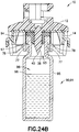
- the horizontal shield wall of the adapter may define a spike cavity that is configured to receive the spike when the adapter is in the vial position.
- the access device connection element may include a plurality of external latches spaced around a periphery of the outer portion of the adapter, with the vial access device defining a plurality of slots configured to receive the plurality of external latches when the adapter is in the shield position.
- the access device connection element may include a plurality of locking apertures spaced around a periphery of the outer portion of the adapter, with the vial access device comprising a locking protrusion configured to be received by the plurality of locking apertures when the adapter is in the shield position.
- distal refers to a direction generally toward an end of a component adapted for contact with a container, such as a vial
- proximal refers to the opposite direction of distal, i.e., away from the end of a component adapted for engagement with the container.
- a first system for the closed transfer of fluids 10 includes a vial access device 12 attachable to a first vial 80 having a first vial size 81 ( Figs. 21-22B ) and a first adapter 14 transitionable between a shield position ( Figs. 11-14B ) in which first adapter 14 is attachable to vial access device 12 such that first adapter 14 shields a spike member 38 of vial access device 12 and a vial position ( Figs.
- first adapter 14 provides reversibility between a shield configuration in which first adapter 14 shields spike member 38 of vial access device 12 to prevent spike stick injuries and an adapter configuration in which first adapter 14 allows first system 10 to accommodate a plurality of vials having different sizes.
- vial access device 12 provides substantially leak-proof sealing during engagement of a cannula with a vial, during transfer of a substance from a vial chamber to a barrel chamber via the cannula, and during disengagement of the cannula from the vial.
- first system 10 provides substantially leak-proof sealing during engagement of a cannula with a vial, during transfer of a substance from a vial chamber to a barrel chamber via the cannula, and during disengagement of the cannula from the vial.
- First system 10 is compatible with a needle and syringe assembly for accessing a medication contained within a vial for administering the medication to a patient.
- First system 10 is also compatible to be used with a drug reconstitution system.
- first system 10 is capable of accommodating a plurality of vials having different sizes.
- first vial 80 defining a first vial size 81 may be a standard drug vial of any type having an open head portion 83 covered by a pierceable septum 84 of an elastomeric material. Walls 85 of first vial 80 define vial chamber 86 for containing a first substance 88.
- First vial 80 includes flange 87 located adjacent open head portion 83. Vial septum 84 is engaged with head portion 83 of first vial 80 to seal the first substance 88 within vial chamber 86. Referring to Figs.
- second vial 90 defining a second vial size 91 may be a standard drug vial of any type having an open head portion 93 covered by a pierceable septum 94 of an elastomeric material. Walls 95 of second vial 90 define vial chamber 96 for containing a second substance 98. Second vial 90 includes flange 97 located adjacent open head portion 93. Vial septum 94 is engaged with head portion 93 of second vial 90 to seal the second substance 98 within vial chamber 96. In one aspect, second vial size 91 is less than first vial size 81.
- Vial access device 12 and first adapter 14 provide a first system 10 that is capable of accommodating a plurality of vials having different sizes, e.g., first vial 80 having first vial size 81 and second vial 90 having second vial size 91.
- vial access device 12 and first adapter 14 are compatible with a first vial 80 comprising a 20 mm vial and a second vial 90 comprising a 13 mm vial.
- vial access device 12 and first adapter 14 are compatible with a first vial 80 comprising a 28 mm vial and a second vial 90 comprising a 20 mm vial.
- vial access device 12 and first adapter 14 are compatible with a first vial 80 comprising a 32 mm vial and a second vial 90 comprising a 28 mm vial. In other aspects, it is envisioned that vial access device 12 and first adapter 14 are compatible with a first vial 80 comprising other vial sizes and a second vial 90 comprising other vial sizes, wherein the second vial size is less than the first vial size.
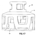
- a second system for the closed transfer of fluids 20 includes vial access device 12 attachable to first vial 80 having first vial size 81 ( Figs. 21-22B ) and a second adapter 24 transitionable between a shield position ( Figs. 17-18B ) in which second adapter 24 is attachable to vial access device 12 such that second adapter 24 shields a spike member 38 of vial access device 12 and a vial position ( Figs.
- second adapter 24 is attachable to second vial 90 defining second vial size 91, the second vial size 91 different than the first vial size 81.
- second adapter 24 provides reversibility between a shield configuration in which second adapter 24 shields spike member 38 of vial access device 12 to prevent spike stick injuries and an adapter configuration in which second adapter 24 allows second system 20 to accommodate a plurality of vials having different sizes.
- vial access device 12 provides substantially leak-proof sealing during engagement of a cannula with a vial, during transfer of a substance from a vial chamber to a barrel chamber via the cannula, and during disengagement of the cannula from the vial.
- second system 20 provides substantially leak-proof sealing during engagement of a cannula with a vial, during transfer of a substance from a vial chamber to a barrel chamber via the cannula, and during disengagement of the cannula from the vial.
- Second system 20 is compatible with a needle and syringe assembly for accessing a medication contained within a vial for administering the medication to a patient. Second system 20 is also compatible to be used with a drug reconstitution system.
- Vial access device 12 and second adapter 24 provide a second system 20 that is capable of accommodating a plurality of vials having different sizes, e.g., first vial 80 having first vial size 81 and second vial 90 having second vial size 91.
- vial access device 12 and second adapter 24 are compatible with a first vial 80 comprising a 20 mm vial and a second vial 90 comprising a 13 mm vial.
- vial access device 12 and second adapter 24 are compatible with a first vial 80 comprising a 28 mm vial and a second vial 90 comprising a 20 mm vial.
- vial access device 12 and second adapter 24 are compatible with a first vial 80 comprising a 32 mm vial and a second vial 90 comprising a 28 mm vial. In other aspects, it is envisioned that vial access device 12 and second adapter 24 are compatible with a first vial 80 comprising other vial sizes and a second vial 90 comprising other vial sizes, wherein the second vial size is less than the first vial size.
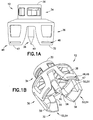
- vial access device 12 generally includes first or proximal end 30; opposing second or distal end 32; neck portion 34 disposed adjacent first end 30; body portion 36 disposed adjacent second end 32; spike member 38 including piercing tip 40; fluid transfer channel 42; pressure normalization channel 44; first adapter connection elements 46 comprising end walls 47 and slots 48; second adapter connection elements 50 comprising locking protrusions 51; and vial connection element 52 comprising vial grip members 54, hook protrusions 56, and angled walls 58.
- neck portion 34 may include a guiding groove arranged therein to guide corresponding guiding protrusions on a syringe adapter, for example, to establish a secure attachment between the syringe adapter and vial access device 12 after which fluid communication can be established.
- first end 30 of vial access device 12 may contain a pierceable barrier member.
- the pierceable barrier member provides for a liquid and gas tight seal between a piercing member and the pierceable barrier member during fluid transfer to minimize leakage and thereby prevent exposure of hazardous medicaments to a user.
- the pierceable barrier member provides a self-sealing seal that, with vial access device 12 attached to a vial, provides a leak-proof seal preventing any substance contained within the vial chamber from being exposed to a health care provider reconstituting, transporting, or administering a drug using system 10.
- the pierceable barrier member comprises a resilient material.
- the pierceable barrier member is preferably a unitary device molded of any flexible, elastomeric material conventionally used for fabricating gas-proof closures.
- the pierceable barrier member may be formed of a natural rubber material, polyurethane elastomers, butyl rubbers, or similar materials. It is contemplated that the pierceable barrier member is formed of a material having a Shore A hardness of approximately 10 to 50.
- the pierceable barrier member can have other material hardness values that would provide an appropriate self-sealing material to provide a leak-proof seal with a vial septum of a vial and an syringe adapter, thereby preventing any liquid or medication residue from being exposed to a health care provider reconstituting, transporting, or administering a drug using system 10.
- Second end 32 of vial access device 12 is substantially formed by body portion 36.
- a piercing member or spike member 38 protruding out from body portion 36 at second end 32 of vial access device 12 is a piercing member or spike member 38 which includes piercing tip 40.
- the spike member 38 extends in a direction substantially parallel with the plurality of vial grip members 54 and serves the purpose of piercing a fluid container such as first vial 80 during assembly of vial access device 12 to a first vial 80 as is shown in greater detail in Fig. 22B .
- a fluid transfer channel 42 extends through spike member 38 such that piercing tip 40 is in fluid communication with first end 30 of vial access device 12.
- the purpose of fluid transfer channel 42 is to permit a needle cannula to extend through vial access device 12 and to thereby permit fluid to be transferred through vial access device 12.
- fluid transfer channel 42 extends inside of spike member 38 as shown in Fig. ID.
- a pressure normalization channel 44 extends from enter aperture 43 to exit aperture 45.
- Pressure normalization channel 44 is arranged to provide gas communication between a pressure equalization system and the interior of a vial when the vial access device 12 is connected to a vial.
- a syringe or cannula assembly may be used to inject fluid into the vial or to withdraw fluid therefrom.
- Any suitable pressure equalization arrangement may be utilized.
- an accordion bellows pressure equalization system may be utilized as discussed in more detail below.
- a pressure equalization system with a system of the present disclosure provides a system for the closed transfer of fluids that provides substantially leak-proof sealing and pressure equalization during engagement of a cannula with a vial, during transfer of a substance from a vial chamber to a barrel chamber via the cannula, and during disengagement of the cannula from the vial.
- the vial access device 12 may be a vial access device only and not include a pressure equalization arrangement and/or sealing arrangement.
- a vial connection element 52 is disposed at second end 32 of vial access device 12.
- vial connection element 52 includes a plurality of vial grip members 54 having hook protrusions 56 and angled walls 58.
- vial grip members 54 are elastically deformable.
- Vial grip members 54 are attachable to a first vial 80 to secure vial access device 12 to the first vial 80.
- Each vial grip member 54 includes a hook protrusion 56 arranged to engage a corresponding flange 87 on a container such as first vial 80 as shown in Figs. 21-22B .
- Vial connection element 52 of vial access device 12 may be dimensioned to be attached to containers of any size and volume.
- vial connection element 52 of vial access device 12 may include other connection mechanisms for securing vial access device 12 to first vial 80 such as a threaded portion, a snap fit mechanism, locking tabs, or other similar mechanism.
- Each vial grip member 54 includes an angled wall 58 arranged to provide a lead-in surface to center and align vial access device 12 on a vial.
- vial access device 12 includes a first adapter connection element 46 and a second adapter connection element 50.
- first adapter connection element 46 comprises a plurality of slots 48. Slots 48 are spaced a distance from one another as shown in Figs. 1A-1C .
- second adapter connection element 50 comprises a plurality of locking protrusions 51. Locking protrusions 51 are spaced a distance from one another as shown in Figs. 1A-1C .
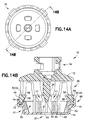
- first adapter 14 generally includes horizontal shield wall 60; outer portion 61 extending from the periphery of horizontal shield wall 60, outer portion 61 comprising outer shield wall 62; inner portion 64 extending from horizontal shield wall 60 and disposed within outer portion 61, inner portion 64 comprising a plurality of inner shield walls 65 defining spike shield area 66; spike cavity 67 defined within a central region of horizontal shield wall 60; access device connection element 68 comprising a plurality of external latches 70 defining a vial access device receiving area 72 and including a locking rib 74; alignment guides 75; and vial connection element 76 comprising vial grip members 77, hook protrusions 78, and angled walls 79.
- First adapter 14 is transitionable between a shield position ( Figs. 11-14B ) in which first adapter 14 is attachable to vial access device 12 such that first adapter 14 shields a spike member 38 of vial access device 12 and a vial position ( Figs. 15-16B and 23-24B ) in which first adapter 14 is attachable to a second vial 90 defining a second vial size 91, the second vial size 91 different than the first vial size 81.
- first adapter 14 provides reversibility between a shield configuration in which first adapter 14 shields spike member 38 of vial access device 12 to prevent spike stick injuries and an adapter or vial configuration in which first adapter 14 allows first system 10 to accommodate a plurality of vials having different sizes.
- first adapter 14 provides a physical barrier that shields spike member 38 of vial access device 12 and prevents the fingers of a user from contacting piercing tip 40 of spike member 38.
- access device connection element 68 of first adapter 14 includes a plurality of external latches 70 spaced around a periphery of outer shield wall 62 as shown in Fig. 2 .
- External latches 70 are engageable with slots 48 of vial access device 12 to attach first adapter 14 to vial access device 12 with the first adapter 14 in the shield position to shield spike member 38 of vial access device 12 as shown in Fig. 14B and as described in more detail below.
- external latches 70 are elastically deformable.
- inner shield walls 65 of first adapter 14 include a vial connection element 76.
- vial connection element 76 includes a plurality of vial grip members 77 having hook protrusions 78 and angled walls 79.
- vial grip members 77 are elastically deformable.
- Vial grip members 77 are attachable to a second vial 90 to secure first system 10 to the second vial 90.
- Each vial grip member 77 includes a hook protrusion 78 arranged to engage a corresponding flange 97 on a container such as second vial 90 as shown in Figs. 23-24B .
- Vial connection element 76 of first adapter 14 may be dimensioned to be attached to containers of any size and volume.
- vial connection element 76 of first adapter 14 may include other connection mechanisms for securing first adapter 14 to second vial 90 such as a threaded portion, a snap fit mechanism, locking tabs, or other similar mechanism.
- Each vial grip member 77 includes an angled wall 79 arranged to provide a lead-in surface to center and align first system 10 on a vial.
- first adapter 14 is attachable to vial access device 12 such that first adapter 14 shields a spike member 38 of vial access device 12 in a shield position.
- First adapter 14 is attachable to vial access device 12 by engagement of access device connection elements 68 of first adapter 14 with first adapter connection elements 46 of vial access device 12.
- end walls 47 of first adapter connection elements 46 can be positioned into respective vial access device receiving areas 72 of external latches 70 of first adapter 14 as shown in Figs. 11 and 14B . In this position, a force can be exerted on vial access device 12 to push vial access device 12 into engagement with external latches 70 of first adapter 14.
- first adapter 14 As force is exerted on vial access device 12 to axially move vial access device 12 into engagement with first adapter 14, external latches 70 of first adapter 14 cooperate with first adapter connection elements 46 of vial access device 12 and deform outward so that end walls 47 of first adapter connection elements 46 move axially downward into vial access device receiving areas 72 of external latches 70 until locking ribs 74 of external latches 70 engage respective slots 48 of first adapter connection elements 46 and lock first adapter 14 to vial access device 12 in the shield position as shown in Figs. 11-14B . In this manner, first adapter 14 is secured to vial access device 12 such that first adapter 14 is prevented from significant relative movement relative to vial access device 12.
- first adapter 14 is particularly advantageous in that it allows a user, such as a patient and/or healthcare worker, to safely handle vial access device 12 without receiving spike stick injuries from piercing tip 40 of spike member 38.
- first adapter 14 With first adapter 14 in the shield position as described above, first adapter 14 provides a physical barrier preventing the fingers of a user from contacting piercing tip 40 of spike member 38. In this manner, the user is prevented from spike stick injuries and the user can conveniently and safely handle vial access device 12 and remove vial access device 12 from packaging.
- An adapter of the present disclosure is also advantageous in that it protects the package integrity.
- first adapter 14 may be removed from vial access device 12.
- vial access device 12 can be used and attached to first vial 80 as shown in Figs. 21-22B .
- Vial grip members 54 of vial access device 12 are attachable to first vial 80 to secure vial access device 12 to first vial 80.
- Each vial grip member 54 includes a hook protrusion 56 arranged to engage a corresponding flange 87 on a container such as first vial 80 as shown in Fig.
- vial access device 12 provides substantially leak-proof sealing during engagement of a cannula with first vial 80, during transfer of a substance from vial chamber 86 to a barrel chamber via the cannula, and during disengagement of the cannula from first vial 80.
- first adapter 14 may be removed from vial access device 12.
- first adapter 14 can be used and attached to second vial 90 as shown in Figs. 23-24B .
- first adapter 14 can be rotated from the shield position as shown in Figs. 11-14B to the vial position as shown in Figs.
- first adapter 14 can be used and attached to second vial 90 as shown in Figs. 23-24B .
- Figs. 23-24B illustrate vial access device 12 and first adapter 14 attached to second vial 90
- first adapter 14 can first be attached to second vial 90 and used to align and guide vial access device 12 during its installation onto second vial 90 as described below.
- the first adapter 14 is secured to the vial access device 12 by the vial grip members 54 of the vial access device 12 engaging the bottom of the outer portion 61 of the first adapter 14.
- the vial grip members 54 may be secured to the first adapter 14 in the same manner that the vial grip members 54 are secured to the flange 87 on the first vial 80 as described above.
- Vial grip members 77 of first adapter 14 are attachable to second vial 90 to secure vial access device 12 to second vial 90 via first adapter 14 as shown in Figs. 23-24B .
- Each vial grip member 77 of first adapter 14 includes a hook protrusion 78 arranged to engage a corresponding flange 97 on a container such as second vial 90 as shown in Fig. 24B . Referring to Figs.
- first system 10 provides substantially leak-proof sealing during engagement of a cannula with second vial 90, during transfer of a substance from vial chamber 96 to a barrel chamber via the cannula, and during disengagement of the cannula from second vial 90.
- alignment guides 75 of first adapter 14 provide a functional benefit by acting as alignment guides for positioning vial access device 12 during its installation onto second vial 90.
- spike member 38 of vial access device 12 is able to extend through spike cavity 67 of first adapter 14 as shown in Fig. 16B .
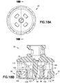
- second adapter 24 generally includes horizontal shield wall 100; outer portion 101 extending from the periphery of horizontal shield wall 100, outer portion 101 comprising outer shield wall 102; inner portion 104 extending from horizontal shield wall 100 and disposed within outer portion 101, inner portion 104 comprising a plurality of inner shield walls 105 defining spike shield area 106; spike cavity 107 defined within a central region of horizontal shield wall 100; access device connection element 108 comprising a plurality of internal latches or locking apertures 110; and vial connection element 116 comprising vial grip members 117, hook protrusions 118, and angled walls 119.
- Second adapter 24 is transitionable between a shield position ( Figs. 17-18B ) in which second adapter 24 is attachable to vial access device 12 such that second adapter 24 shields a spike member 38 of vial access device 12 and a vial position ( Figs. 19-20B and 25-26B ) in which second adapter 24 is attachable to a second vial 90 defining a second vial size 91 , the second vial size 91 different than the first vial size 81.
- second adapter 24 provides reversibility between a shield configuration in which second adapter 24 shields spike member 38 of vial access device 12 to prevent spike stick injuries and an adapter or vial configuration in which second adapter 24 allows second system 20 to accommodate a plurality of vials having different sizes.
- horizontal shield wall 100 and inner shield walls 105 together define a spike shield area 106 which is sized and configured to receive and shield spike member 38 of vial access device 12 with second adapter 24 in a shield position.
- second adapter 24 provides a physical barrier that shields spike member 38 of vial access device 12 and prevents the fingers of a user from contacting piercing tip 40 of spike member 38.
- access device connection element 108 of second adapter 24 includes a plurality of internal latches or locking apertures 100 spaced around a periphery of outer shield wall 102 as shown in Fig. 6 .
- Internal latches 100 are engageable with locking protrusions 51 of vial access device 12 to attach second adapter 24 to vial access device 12 with the second adapter 24 in the shield position to shield spike member 38 of vial access device 12 as shown in Fig. 18B and as described in more detail below.
- inner shield walls 105 of second adapter 24 include a vial connection element 116.
- vial connection element 116 includes a plurality of vial grip members 117 having hook protrusions 118 and angled walls 119.
- vial grip members 117 are elastically deformable.
- Vial grip members 117 are attachable to a second vial 90 to secure second system 20 to the second vial 90.
- Each vial grip member 117 includes a hook protrusion 118 arranged to engage a corresponding flange 97 on a container such as second vial 90 as shown in Figs. 25-26B .
- Vial connection element 116 of second adapter 24 may be dimensioned to be attached to containers of any size and volume.
- vial connection element 116 of second adapter 24 may include other connection mechanisms for securing second adapter 24 to second vial 90 such as a threaded portion, a snap fit mechanism, locking tabs, or other similar mechanism.
- Each vial grip member 117 includes an angled wall 119 arranged to provide a lead-in surface to center and align second system 20 on a vial.
- second adapter 24 is attachable to vial access device 12 such that second adapter 24 shields a spike member 38 of vial access device 12 in a shield position.
- Second adapter 24 is attachable to vial access device 12 by engagement of access device connection elements 108 of second adapter 24 with second adapter connection elements 50 of vial access device 12.
- locking protrusions 51 of second adapter connection elements 50 can be positioned into engagement with respective locking apertures 110 of second adapter 24 as shown in Figs. 17 and 18B .
- a force can be exerted on vial access device 12 to push vial access device 12 into engagement with locking apertures 110 of second adapter 24.
- vial access device 12 As force is exerted on vial access device 12 to axially move vial access device 12 into engagement with second adapter 24, locking protrusions 51 of vial access device 12 cooperate with outer shield wall 102 of second adapter 24 and deform outward so that second adapter connection elements 50 of vial access device 12 move axially downward until locking protrusions 51 of vial access device 12 snap into engagement with respective locking apertures 110 of second adapter 24 and lock second adapter 24 to vial access device 12 in the shield position as shown in Figs. 17-18B .
- second adapter 24 is secured to vial access device 12 such that second adapter 24 is prevented from significant relative movement relative to vial access device 12.
- vial access device 12 does not need to contain slots 48 when used with second adapter 24 and second system 20.
- second adapter 24 is particularly advantageous in that it allows a user, such as a patient and/or healthcare worker, to safely handle vial access device 12 without receiving spike stick injuries from piercing tip 40 of spike member 38.
- second adapter 24 With second adapter 24 in the shield position as described above, second adapter 24 provides a physical barrier preventing the fingers of a user from contacting piercing tip 40 of spike member 38. In this manner, the user is prevented from spike stick injuries and the user can conveniently and safely handle vial access device 12 and remove vial access device 12 from packaging.
- An adapter of the present disclosure is also advantageous in that it protects the package integrity.
- second adapter 24 may be removed from vial access device 12.
- vial access device 12 can be used and attached to first vial 80 as shown in Figs. 21-22B and as described above.
- second adapter 24 may be removed from vial access device 12.
- second adapter 24 can be used and attached to second vial 90 as shown in Figs. 25-26B .
- second adapter 24 can be rotated from the shield position as shown in Figs. 17-18B to the vial position as shown in Figs.
- second adapter 24 can be used and attached to second vial 90 as shown in Figs. 25-26B .
- Vial grip members 117 of second adapter 24 are attachable to second vial 90 to secure vial access device 12 to second vial 90 via second adapter 24 as shown in Figs. 25-26B .
- the second adapter 24 may be secured to the second vial 90 first with the vial access device 12 subsequently placed onto the second adapter 24.
- the second adapter 24 is secured to the vial access device 12 by the vial grip members 54 of the vial access device 12 engaging the bottom of the outer portion 101 of the second adapter 24.
- the vial grip members 54 may be secured to the second adapter 24 in the same manner that the vial grip members 54 are secured to the flange 87 on the first vial 80 as described above.
- Each vial grip member 117 of second adapter 24 includes a hook protrusion 118 arranged to engage a corresponding flange 97 on a container such as second vial 90 as shown in Fig. 26B .
- second system 20 provides substantially leak-proof sealing during engagement of a cannula with second vial 90, during transfer of a substance from vial chamber 96 to a barrel chamber via the cannula, and during disengagement of the cannula from second vial 90.
- spike member 38 of vial access device 12 is able to extend through spike cavity 107 of second adapter 24 as shown in Fig. 20B .
- a third system for the closed transfer of fluids 300 includes a vial access device or vial access device housing component 202 attachable to a first vial 80 having a first vial size 81 ( Figs. 53-54B ) and a third adapter 204 transitionable between a shield position ( Figs. 42- 46B ) in which third adapter 204 is attachable to vial access device 202 such that third adapter 204 shields a spike member 228 of vial access device 202 and a vial position ( Figs.
- third adapter 204 provides reversibility between a shield configuration in which third adapter 204 shields spike member 228 of vial access device 202 to prevent spike stick injuries and an adapter configuration in which third adapter 204 allows third system 200 to accommodate a plurality of vials having different sizes.
- vial access device 202 provides substantially leak-proof sealing during engagement of a cannula with a vial, during transfer of a substance from a vial chamber to a barrel chamber via the cannula, and during disengagement of the cannula from the vial.
- third system 200 provides substantially leak-proof sealing during engagement of a cannula with a vial, during transfer of a substance from a vial chamber to a barrel chamber via the cannula, and during disengagement of the cannula from the vial.
- the leak-proof sealing of the third system 200 substantially prevents leakage of both air and liquid during use of the third system 200.
- Third system 200 is compatible with a needle and syringe assembly for accessing a medication contained within a vial for administering the medication to a patient.
- Third system 200 is also compatible to be used with a drug reconstitution system.
- first vial 80 defining a first vial size 81 may be a standard drug vial of any type having an open head portion 83 covered by a pierceable septum 84 of an elastomeric material. Walls 85 of first vial 80 define vial chamber 86 for containing a first substance 88. First vial 80 includes flange 87 located adjacent open head portion 83. Vial septum 84 is engaged with head portion 83 of first vial 80 to seal the first substance 88 within vial chamber 86. Referring to Figs.
- second vial 90 defining a second vial size 91 may be a standard drug vial of any type having an open head portion 93 covered by a pierceable septum 94 of an elastomeric material. Walls 95 of second vial 90 define vial chamber 96 for containing a second substance 98. Second vial 90 includes flange 97 located adjacent open head portion 93. Vial septum 84 is engaged with head portion 93 of second vial 90 to seal the second substance 98 within vial chamber 96. In one aspect, second vial size 91 is less than first vial size 81.
- Vial access device 202 and third adapter 204 provide a third system 200 that is capable of accommodating a plurality of vials having different sizes, e.g., first vial 80 having first vial size 81 and second vial 90 having second vial size 91.
- vial access device 202 and third adapter 204 are compatible with a first vial 80 comprising a 20 mm vial and a second vial 90 comprising a 13 mm vial.
- vial access device 202 and third adapter 204 are compatible with a first vial 80 comprising a 28 mm vial and a second vial 90 comprising a 20 mm vial.
- vial access device 202 and third adapter 204 are compatible with a first vial 80 comprising a 32 mm vial and a second vial 90 comprising a 28 mm vial. In other aspects, it is envisioned that vial access device 202 and third adapter 204 are compatible with a first vial 80 comprising other vial sizes and a second vial 90 comprising other vial sizes, wherein the second vial size is less than the first vial size.
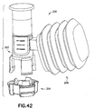
- third system 200 includes vial access device 202, third adapter 204, pressure equalization system 206, connector 208, top housing component 210, and cap component 212.
- Fig. 27 illustrates pressure equalization system 206 an expanded state, although the pressure equalization system also has a non-expanded state (not shown).
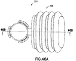
- Third system 200 includes a pressure equalization system 206 that is designed as an accordion bellows which is compressible and expandable and thus the volume of pressure equalization system 206 can thereby be increased and decreased.
- Figs. 41A-56B illustrate pressure equalization system 206 an expanded state, although the pressure equalization system also has a non-expanded state (not shown).
- Pressure equalization system 206 is either a non-expanded state or an expanded state, e.g., pressure equalization system 206 is transitionable between a non-expanded state and an expanded state.
- third system 200 includes either top housing component 210 or cap component 212 but not both.
- vial access device 202, pressure equalization system 206, connector 208, top housing component 210, and cap component 212 form a single integral component.
- vial access device 202, pressure equalization system 206, connector 208, top housing component 210, and cap component 212 are separate components that are attachable theretogether to form a vial access device housing component.
- the connector 208 is a bayonet-style connection, although the connection 208 may be embodied as any other suitable connection arrangement.
- Third system 200 provides substantially leak-proof sealing and pressure balancing during engagement of a cannula with a vial, during transfer of a substance from a vial chamber to a barrel chamber via the cannula, and during disengagement of the cannula from the vial.
- the leak-proof sealing of the third system 200 substantially prevents leakage of both air and liquid during use of the third system 200.
- Third system 200 is compatible with a needle and syringe assembly for accessing a medication contained within a vial for administering the medication to a patient.
- Third system 200 is also compatible to be used with a drug reconstitution system as will be described in more detail below.
- vial access device 202 generally includes first end 220; opposing second end 222; neck portion 224 disposed adjacent first end 220; body portion 226 disposed adjacent second end 222; spike member 228 including piercing tip 230; fluid transfer channel 232; pressure normalization channel 234; pressure chamber 238; first adapter connection elements 240 comprising locking ribs 242; second adapter connection elements 244; vial connection element 246 comprising vial grip members 248, hook protrusions 250, and angled walls 252; arm portion 254; and pressure equalization connection wall 256.
- First end 220 of vial access device 202 is substantially formed by neck portion 224.
- neck portion 224 may include a guiding groove arranged therein to guide corresponding guiding protrusions on a syringe adapter, for example, to establish a secure attachment between the syringe adapter and vial access device 202 after which fluid communication can be established.
- first end 220 of vial access device 202 may contain a pierceable barrier member.
- the pierceable barrier member provides for a liquid and gas tight seal between a piercing member and the pierceable barrier member during fluid transfer to minimize leakage and thereby prevent exposure of hazardous medicaments to a user.
- the pierceable barrier member provides a self-sealing seal that, with vial access device 202 attached to a vial, provides a leak-proof seal preventing any substance contained within the vial chamber from being exposed to a health care provider reconstituting, transporting, or administering a drug using third system 200.
- the pierceable barrier member comprises a resilient material.
- the pierceable barrier member is preferably a unitary device molded of any flexible, elastomeric material conventionally used for fabricating gas-proof closures.
- the pierceable barrier member may be formed of a natural rubber material, polyurethane elastomers, butyl rubbers, or similar materials. It is contemplated that the pierceable barrier member is formed of a material having a Shore A hardness of approximately 10 to 50.
- the pierceable barrier member can have other material hardness values that would provide an appropriate self-sealing material to provide a leak-proof seal with a vial septum of a vial and a syringe adapter, thereby preventing any liquid or medication residue from being exposed to a health care provider reconstituting, transporting, or administering a drug using third system 200.
- Second end 222 of vial access device 202 is substantially formed by body portion 226.
- a piercing member or spike member 228 protruding out from body portion 226 at second end 222 of vial access device 202 is a piercing member or spike member 228 which includes piercing tip 230.
- the spike member 228 extends in a direction substantially parallel with the plurality of vial grip members 248 and serves the purpose of piercing a fluid container such as first vial 80 during assembly of vial access device 202 to a first vial 80 as is shown in greater detail in Fig. 54B .
- a fluid transfer channel 232 extends through spike member 228 such that piercing tip 230 is in fluid communication with first end 220 of vial access device 202.
- the purpose of fluid transfer channel 232 is to permit a needle cannula to extend through vial access device 202 and to thereby permit fluid to be transferred through vial access device 202.
- fluid transfer channel 232 extends inside of spike member 228 as shown in Fig. 33B .
- a pressure normalization channel 234 extends from enter aperture 235 to exit aperture 236 and then to pressure chamber 238.
- Pressure normalization channel 234 is arranged to provide gas communication between a pressure equalization system, such as pressure equalization system 206, and the interior of a vial when the vial access device 202 is connected to a vial.
- a syringe or cannula assembly may be used to inject fluid into the vial or to withdraw fluid therefrom.
- a pressure equalization system such as pressure equalization system 206
- a system of the present disclosure provides a system for the closed transfer of fluids that provides substantially leak-proof sealing and pressure equalization during engagement of a cannula with a vial, during transfer of a substance from a vial chamber to a barrel chamber via the cannula, and during disengagement of the cannula from the vial.
- a vial connection element 246 is disposed at second end 222 of vial access device 202.
- vial connection element 246 includes a plurality of vial grip members 248 having hook protrusions 250 and angled walls 252.
- vial grip members 248 are elastically deformable. Vial grip members 248 are attachable to a first vial 80 to secure vial access device 202 to the first vial 80.
- Each vial grip member 248 includes a hook protrusion 250 arranged to engage a corresponding flange 87 on a container such as first vial 80 as shown in Figs. 53-54B .
- Vial connection element 246 of vial access device 202 may be dimensioned to be attached to containers of any size and volume.
- vial connection element 246 of vial access device 202 may include other connection mechanisms for securing vial access device 202 to first vial 80 such as a threaded portion, a snap fit mechanism, locking tabs, or other similar mechanism.
- Each vial grip member 248 includes an angled wall 252 arranged to provide a lead-in surface to center and align vial access device 202 on a vial.
- vial access device 202 includes a first adapter connection element 240 and a second adapter connection element 244. In this manner, vial access device 202 is connectable with third adapter 204 in a shield position and a vial position as discussed in more detail below.
- first adapter connection element 240 comprises a plurality of locking ribs 242. Locking ribs 242 are spaced a distance from one another as shown in Figs. 28-33B .
- pressure equalization system 206 includes receiving slots 207 and pressure equalization system 206 is attachable to pressure equalization connection wall 256 of arm portion 254 of vial access device 202 by engagement of connection wall 256 within receiving slots 207 as shown in Fig. 41B .
- third adapter 204 generally includes horizontal shield wall 270; outer portion 272 extending from the periphery of horizontal shield wall 270, outer portion 272 comprising outer shield wall 274 which defines outer vial access device compartments 276; inner portion 278 extending from horizontal shield wall 270 and disposed within outer portion 272, inner portion 278 comprising a plurality of inner shield walls 280 defining spike shield area 282; spike cavity 284 defined within a central region of horizontal shield wall 270; access device connection element 286 comprising a plurality of locking apertures 288 and a plurality of locking walls 290; and vial connection element 2 9 2 comprising vial grip members 294, hook protrusions 296, and angled walls 298.
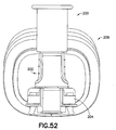
- Third adapter 204 is transitionable between a shield position ( Figs. 42-46B ) in which third adapter 204 is attachable to vial access device 202 such that third adapter 204 shields a spike member 228 of vial access device 202 and a vial position ( Figs. 47-52 and 55-56B ) in which third adapter 204 is attachable to a second vial 90 defining a second vial size 91 , the second vial size 91 different than the first vial size 81.
- third adapter 204 provides reversibility between a shield configuration in which third adapter 204 shields spike member 228 of vial access device 202 to prevent spike stick injuries and an adapter or vial configuration in which third adapter 204 allows third system 200 to accommodate a plurality of vials having different sizes.
- horizontal shield wall 270 and inner shield walls 280 together define a spike shield area 282 which is sized and configured to receive and shield spike member 228 of vial access device 202 with third adapter 204 in a shield position.
- third adapter 204 provides a physical barrier that shields spike member 228 of vial access device 202 and prevents the fingers of a user from contacting piercing tip 230 of spike member 228.
- access device connection element 286 of third adapter 204 includes a plurality of locking apertures 288 spaced around a periphery of outer shield wall 274 as shown in Fig. 35 .
- Locking apertures 288 are engageable with locking ribs 242 of vial access device 202 to attach third adapter 204 to vial access device 202 with the third adapter 204 in the shield position to shield spike member 228 of vial access device 202 as shown in Figs. 42-46B and as described in more detail below.
- inner shield walls 280 of third adapter 204 include a vial connection element 292.
- vial connection element 292 includes a plurality of vial grip members 294 having hook protrusions 296 and angled walls 298.
- vial grip members 294 are elastically deformable. Vial grip members 294 are attachable to a second vial 90 to secure third system 200 to the second vial 90.
- Each vial grip member 294 includes a hook protrusion 296 arranged to engage a corresponding flange 97 on a container such as second vial 90 as shown in Figs. 55-56B .
- Vial connection element 292 of third adapter 204 may be dimensioned to be attached to containers of any size and volume.
- vial connection element 292 of third adapter 204 may include other connection mechanisms for securing third adapter 204 to second vial 90 such as a threaded portion, a snap fit mechanism, locking tabs, or other similar mechanism.
- Each vial grip member 294 includes an angled wall 298 arranged to provide a lead-in surface to center and align third system 200 on a vial.
- third adapter 204 is attachable to vial access device 202 such that third adapter 204 shields a spike member 228 of vial access device 202 in a shield position.
- Third adapter 204 is attachable to vial access device 202 by engagement of locking apertures 288 of third adapter 204 with locking ribs 242 of vial access device 202 to attach third adapter 204 to vial access device 202 with the third adapter 204 in the shield position to shield spike member 228 of vial access device 202 as shown in Figs. 42- 46 B.
- third adapter 204 is secured to vial access device 202 such that third adapter 204 is prevented from significant relative movement relative to vial access device 202.
- third adapter 204 is particularly advantageous in that it allows a user, such as a patient and/or healthcare worker, to safely handle vial access device 202 without receiving spike stick injuries from piercing tip 230 of spike member 228.
- third adapter 204 With third adapter 204 in the shield position as described above, third adapter 204 provides a physical barrier preventing the fingers of a user from contacting piercing tip 230 of spike member 228. In this manner, the user is prevented from spike stick injuries and the user can conveniently and safely handle vial access device 202 and remove vial access device 202 from packaging.
- third adapter 204 may be removed from vial access device 202.
- vial access device 202 can be used and attached to first vial 80 as shown in Figs. 53-54B .
- Vial grip members 248 of vial access device 202 are attachable to first vial 80 to secure vial access device 202 to first vial 80.
- Each vial grip member 248 includes a hook protrusion 250 arranged to engage a corresponding flange 87 on a container such as first vial 80 as shown in Fig. 54B .
- vial access device 202 With vial access device 202 attached to first vial 80, vial access device 202 provides substantially leak-proof sealing during engagement of a cannula with first vial 80, during transfer of a substance from vial chamber 86 to a barrel chamber via the cannula, and during disengagement of the cannula from first vial 80.
- third adapter 204 may be removed from vial access device 202.
- third adapter 204 can be used and attached to second vial 90 as shown in Figs. 55-56B .
- third adapter 204 can be rotated from the shield position as shown in Figs.
- third adapter 204 can be used and attached to second vial 90 as shown in Figs. 55-56B .
- the third adapter 204 is secured to the vial access device 202 by the vial grip members 248 of the vial access device 202 engaging the bottom of the outer portion 272 of the third adapter 204.
- the vial grip members 248 may be secured to the third adapter 204 in the same manner that the vial grip members 248 are secured to the flange 87 on the first vial 80 as described above. In this manner, third adapter 204 is secured to vial access device 202 such that third adapter 204 is prevented from significant relative movement relative to vial access device 202.
- Vial grip members 294 of third adapter 204 are attachable to second vial 90 to secure vial access device 202 to second vial 90 via third adapter 204 as shown in Figs. 55-56B .
- Each vial grip member 294 of third adapter 204 includes a hook protrusion 296 arranged to engage a corresponding flange 97 on a container such as second vial 90 as shown in Fig. 56B .
- the third adapter 204 may be secured to the second vial 90 first with the vial access device 202 subsequently secured to the third adapter 204. Referring to Figs.
- third system 200 provides substantially leak-proof sealing during engagement of a cannula with second vial 90, during transfer of a substance from vial chamber 96 to a barrel chamber via the cannula, and during disengagement of the cannula from second vial 90.
- spike member 228 of vial access device 202 is able to extend through spike cavity 284 of third adapter 204 as shown in Fig. 56B .
Landscapes
- Health & Medical Sciences (AREA)
- Pharmacology & Pharmacy (AREA)
- Life Sciences & Earth Sciences (AREA)
- Animal Behavior & Ethology (AREA)
- General Health & Medical Sciences (AREA)
- Public Health (AREA)
- Veterinary Medicine (AREA)
- Physics & Mathematics (AREA)
- Fluid Mechanics (AREA)
- Medical Preparation Storing Or Oral Administration Devices (AREA)
Applications Claiming Priority (2)
| Application Number | Priority Date | Filing Date | Title |
|---|---|---|---|
| US201361900562P | 2013-11-06 | 2013-11-06 | |
| PCT/US2014/063896 WO2015069649A1 (en) | 2013-11-06 | 2014-11-04 | Adapter for vial access device |
Publications (2)
| Publication Number | Publication Date |
|---|---|
| EP3065693A1 EP3065693A1 (en) | 2016-09-14 |
| EP3065693B1 true EP3065693B1 (en) | 2019-02-06 |
Family
ID=52021414
Family Applications (1)
| Application Number | Title | Priority Date | Filing Date |
|---|---|---|---|
| EP14810046.4A Active EP3065693B1 (en) | 2013-11-06 | 2014-11-04 | Adapter for vial access device |
Country Status (8)
| Country | Link |
|---|---|
| US (2) | US10391031B2 (zh) |
| EP (1) | EP3065693B1 (zh) |
| JP (1) | JP6280216B2 (zh) |
| CN (1) | CN105873558B (zh) |
| CA (1) | CA2929480C (zh) |
| ES (1) | ES2722410T3 (zh) |
| IL (1) | IL245396B (zh) |
| WO (1) | WO2015069649A1 (zh) |
Families Citing this family (41)
| Publication number | Priority date | Publication date | Assignee | Title |
|---|---|---|---|---|
| US10076272B2 (en) | 2011-04-26 | 2018-09-18 | Velano Vascular, Inc. | Systems and methods for phlebotomy through a peripheral IV catheter |
| US8366685B2 (en) | 2011-04-26 | 2013-02-05 | Creative Vascular, Llc | Systems and methods for phlebotomy through a peripheral IV catheter |
| IL221634A0 (en) | 2012-08-26 | 2012-12-31 | Medimop Medical Projects Ltd | Universal drug vial adapter |
| GB2533714B (en) | 2013-08-07 | 2020-04-08 | Medimop Medical Projects Ltd | Liquid transfer devices for use with infusion liquid containers |
| WO2015134431A1 (en) | 2014-03-03 | 2015-09-11 | Magnolia Medical Technologies, Inc. | Apparatus and methods for disinfection of a specimen container |
| JP6358724B2 (ja) | 2015-01-05 | 2018-07-18 | ウエスト・ファーマ.サービシーズ・イスラエル,リミテッド | 正確な使用を確保するための簡易着脱式薬瓶アダプタを有するデュアルバイアルアダプタアセンブリ |
| EP3319576B1 (en) | 2015-07-16 | 2019-10-02 | West Pharma. Services IL, Ltd | Liquid drug transfer devices for secure telescopic snap fit on injection vials |
| US10039913B2 (en) | 2015-07-30 | 2018-08-07 | Carefusion 303, Inc. | Tamper-resistant cap |
| EP3380058B1 (en) | 2015-11-25 | 2020-01-08 | West Pharma Services IL, Ltd. | Dual vial adapter assemblage including drug vial adapter with self-sealing access valve |
| WO2017172364A1 (en) | 2016-03-29 | 2017-10-05 | Phipps Innovations, Llc | System, apparatus, and method for extending the useful life of medicine |
| IL245803A0 (en) | 2016-05-24 | 2016-08-31 | West Pharma Services Il Ltd | Devices with two vial adapters include an aerated drug vial adapter and an aerated liquid vial adapter |
| IL245800A0 (en) | 2016-05-24 | 2016-08-31 | West Pharma Services Il Ltd | A device with two vial adapters includes two identical vial adapters |
| IL246073A0 (en) | 2016-06-06 | 2016-08-31 | West Pharma Services Il Ltd | A fluid transport device for use with a slide-driven piston medicine pump cartridge |
| IL247376A0 (en) | 2016-08-21 | 2016-12-29 | Medimop Medical Projects Ltd | Injector assembly |
| JP6769190B2 (ja) * | 2016-09-07 | 2020-10-14 | 株式会社ジェイ・エム・エス | バイアルアダプタ |
| USD832430S1 (en) * | 2016-11-15 | 2018-10-30 | West Pharma. Services IL, Ltd. | Dual vial adapter assemblage |
| IL249408A0 (en) | 2016-12-06 | 2017-03-30 | Medimop Medical Projects Ltd | A device for transporting fluids for use with an infusion fluid container and a hand tool similar to a plunger to release a vial from it |
| CN114470485A (zh) | 2017-03-21 | 2022-05-13 | 威蓝诺血管股份有限公司 | 通过已放置的外周静脉导管进行流体输送的装置和方法 |
| EP4059556A1 (en) | 2017-03-21 | 2022-09-21 | Velano Vascular, Inc. | Methods for controlling catheter device size |
| IL251458A0 (en) | 2017-03-29 | 2017-06-29 | Medimop Medical Projects Ltd | Liquid drug delivery devices are user-operated for use in pre-prepared liquid drug delivery assemblies (rtu) |
| IL254802A0 (en) | 2017-09-29 | 2017-12-31 | Medimop Medical Projects Ltd | A device with two vial adapters includes two identical perforated vial adapters |
| USD877900S1 (en) | 2018-04-04 | 2020-03-10 | Becton Dickinson and Company Limited | Medical infusion adapter |
| USD888945S1 (en) | 2018-04-04 | 2020-06-30 | Becton Dickinson and Company Limited | Medical connector |
| USD873996S1 (en) | 2018-04-04 | 2020-01-28 | Becton Dickinson and Company Limited | Medical syringe adapter |
| USD908872S1 (en) | 2018-04-04 | 2021-01-26 | Becton Dickinson and Company Limited | Medical vial access device |
| US11224555B2 (en) | 2018-04-23 | 2022-01-18 | Hospira, Inc. | Access and vapor containment system for a drug vial and method of making and using same |
| ES2937009T3 (es) * | 2018-05-25 | 2023-03-23 | Becton Dickinson France | Conector para conectar un dispositivo de inyección médico a un recipiente |
| JP1630477S (zh) | 2018-07-06 | 2019-05-07 | ||
| JP7385661B2 (ja) * | 2018-11-30 | 2023-11-22 | ジェネンテック, インコーポレイテッド | バイアル検査方法および装置 |
| USD923812S1 (en) | 2019-01-16 | 2021-06-29 | West Pharma. Services IL, Ltd. | Medication mixing apparatus |
| JP1648075S (zh) | 2019-01-17 | 2019-12-16 | ||
| WO2020157719A1 (en) | 2019-01-31 | 2020-08-06 | West Pharma. Services Il, Ltd | Liquid transfer device |
| WO2020222220A1 (en) | 2019-04-30 | 2020-11-05 | West Pharma. Services IL, Ltd. | Liquid transfer device with dual lumen iv spike |
| JP2022545801A (ja) | 2019-08-20 | 2022-10-31 | ベラノ バスキュラー,インコーポレイテッド | 伸長型カテーテルを有する流体移送装置とその使用方法 |
| US11311458B2 (en) * | 2019-09-11 | 2022-04-26 | B Braun Medical Inc. | Binary connector for drug reconstitution |
| CN113208916A (zh) * | 2020-01-21 | 2021-08-06 | 贝克顿·迪金森公司 | 药瓶适配器装置 |
| USD956958S1 (en) | 2020-07-13 | 2022-07-05 | West Pharma. Services IL, Ltd. | Liquid transfer device |
| WO2022076908A2 (en) | 2020-10-09 | 2022-04-14 | Icu Medical, Inc. | Fluid transfer device and method of use for same |
| CA3197752A1 (en) | 2020-11-26 | 2022-06-02 | Avia Vascular, Llc | Blood collection devices, systems, and methods |
| USD1010112S1 (en) | 2021-07-03 | 2024-01-02 | KAIRISH INNOTECH Private Ltd. | Vial adapter with valve |
| KR102423037B1 (ko) * | 2021-11-29 | 2022-07-20 | 주식회사 에스티에스바이오 | 멀티 바이알 어댑터 |
Family Cites Families (11)
| Publication number | Priority date | Publication date | Assignee | Title |
|---|---|---|---|---|
| JPS552186B2 (zh) | 1973-07-20 | 1980-01-18 | ||
| US5112315A (en) * | 1990-10-04 | 1992-05-12 | Retrax, Inc. | Retractable syringe |
| US5647845A (en) * | 1995-02-01 | 1997-07-15 | Habley Medical Technology Corporation | Generic intravenous infusion system |
| US5893397A (en) | 1996-01-12 | 1999-04-13 | Bioject Inc. | Medication vial/syringe liquid-transfer apparatus |
| US20050137566A1 (en) * | 2003-12-23 | 2005-06-23 | Fowles Thomas A. | Sliding reconstitution device for a diluent container |
| FR2789369B1 (fr) * | 1999-02-10 | 2001-04-27 | Biodome | Dispositif de connexion entre un recipient et un contenant et ensemble pret a l'emploi comprenant un tel dispositif |
| US6474375B2 (en) * | 2001-02-02 | 2002-11-05 | Baxter International Inc. | Reconstitution device and method of use |
| US6875205B2 (en) * | 2002-02-08 | 2005-04-05 | Alaris Medical Systems, Inc. | Vial adapter having a needle-free valve for use with vial closures of different sizes |
| SI2463201T1 (sl) * | 2003-10-30 | 2014-06-30 | Teva Medical Ltd. | Naprava za varno obdelavo zdravila |
| JP4405446B2 (ja) | 2005-06-27 | 2010-01-27 | イーエヌ大塚製薬株式会社 | 誤接続防止用スパウト及びパウチ |
| IL221634A0 (en) * | 2012-08-26 | 2012-12-31 | Medimop Medical Projects Ltd | Universal drug vial adapter |
-
2014
- 2014-11-04 CN CN201480072024.6A patent/CN105873558B/zh active Active
- 2014-11-04 US US15/034,388 patent/US10391031B2/en active Active
- 2014-11-04 WO PCT/US2014/063896 patent/WO2015069649A1/en active Application Filing
- 2014-11-04 JP JP2016528083A patent/JP6280216B2/ja active Active
- 2014-11-04 CA CA2929480A patent/CA2929480C/en active Active
- 2014-11-04 EP EP14810046.4A patent/EP3065693B1/en active Active
- 2014-11-04 ES ES14810046T patent/ES2722410T3/es active Active
-
2016
- 2016-05-01 IL IL245396A patent/IL245396B/en unknown
-
2019
- 2019-07-11 US US16/508,938 patent/US11690786B2/en active Active
Non-Patent Citations (1)
| Title |
|---|
| None * |
Also Published As
| Publication number | Publication date |
|---|---|
| CN105873558B (zh) | 2019-07-16 |
| CN105873558A (zh) | 2016-08-17 |
| CA2929480C (en) | 2020-03-31 |
| JP2016535630A (ja) | 2016-11-17 |
| US20160287475A1 (en) | 2016-10-06 |
| US20190328613A1 (en) | 2019-10-31 |
| US10391031B2 (en) | 2019-08-27 |
| IL245396A0 (en) | 2016-06-30 |
| EP3065693A1 (en) | 2016-09-14 |
| JP6280216B2 (ja) | 2018-02-14 |
| US11690786B2 (en) | 2023-07-04 |
| IL245396B (en) | 2021-08-31 |
| ES2722410T3 (es) | 2019-08-09 |
| WO2015069649A1 (en) | 2015-05-14 |
| CA2929480A1 (en) | 2015-05-14 |
Similar Documents
| Publication | Publication Date | Title |
|---|---|---|
| US11690786B2 (en) | Adapter for vial access device | |
| US11273101B2 (en) | System with adapter for closed transfer of fluids | |
| JP6840107B2 (ja) | 流体の閉鎖移送のためのアダプタを有するシステム | |
| US10470974B2 (en) | System for closed transfer of fluids with a locking member | |
| EP2968065B1 (en) | System for closed transfer of fluids | |
| EP2968066B1 (en) | Seal system for cannula |
Legal Events
| Date | Code | Title | Description |
|---|---|---|---|
| PUAI | Public reference made under article 153(3) epc to a published international application that has entered the european phase |
Free format text: ORIGINAL CODE: 0009012 |
|
| 17P | Request for examination filed |
Effective date: 20160601 |
|
| AK | Designated contracting states |
Kind code of ref document: A1 Designated state(s): AL AT BE BG CH CY CZ DE DK EE ES FI FR GB GR HR HU IE IS IT LI LT LU LV MC MK MT NL NO PL PT RO RS SE SI SK SM TR |
|
| AX | Request for extension of the european patent |
Extension state: BA ME |
|
| DAX | Request for extension of the european patent (deleted) | ||
| RAP1 | Party data changed (applicant data changed or rights of an application transferred) |
Owner name: BECTON DICKINSON AND COMPANY LIMITED |
|
| STAA | Information on the status of an ep patent application or granted ep patent |
Free format text: STATUS: EXAMINATION IS IN PROGRESS |
|
| 17Q | First examination report despatched |
Effective date: 20170802 |
|
| GRAP | Despatch of communication of intention to grant a patent |
Free format text: ORIGINAL CODE: EPIDOSNIGR1 |
|
| STAA | Information on the status of an ep patent application or granted ep patent |
Free format text: STATUS: GRANT OF PATENT IS INTENDED |
|
| INTG | Intention to grant announced |
Effective date: 20180711 |
|
| GRAS | Grant fee paid |
Free format text: ORIGINAL CODE: EPIDOSNIGR3 |
|
| GRAJ | Information related to disapproval of communication of intention to grant by the applicant or resumption of examination proceedings by the epo deleted |
Free format text: ORIGINAL CODE: EPIDOSDIGR1 |
|
| GRAL | Information related to payment of fee for publishing/printing deleted |
Free format text: ORIGINAL CODE: EPIDOSDIGR3 |
|
| STAA | Information on the status of an ep patent application or granted ep patent |
Free format text: STATUS: EXAMINATION IS IN PROGRESS |
|
| GRAR | Information related to intention to grant a patent recorded |
Free format text: ORIGINAL CODE: EPIDOSNIGR71 |
|
| STAA | Information on the status of an ep patent application or granted ep patent |
Free format text: STATUS: GRANT OF PATENT IS INTENDED |
|
| INTC | Intention to grant announced (deleted) | ||
| GRAA | (expected) grant |
Free format text: ORIGINAL CODE: 0009210 |
|
| STAA | Information on the status of an ep patent application or granted ep patent |
Free format text: STATUS: THE PATENT HAS BEEN GRANTED |
|
| INTG | Intention to grant announced |
Effective date: 20181220 |
|
| AK | Designated contracting states |
Kind code of ref document: B1 Designated state(s): AL AT BE BG CH CY CZ DE DK EE ES FI FR GB GR HR HU IE IS IT LI LT LU LV MC MK MT NL NO PL PT RO RS SE SI SK SM TR |
|
| REG | Reference to a national code |
Ref country code: GB Ref legal event code: FG4D |
|
| REG | Reference to a national code |
Ref country code: CH Ref legal event code: EP Ref country code: AT Ref legal event code: REF Ref document number: 1094404 Country of ref document: AT Kind code of ref document: T Effective date: 20190215 |
|
| REG | Reference to a national code |
Ref country code: DE Ref legal event code: R096 Ref document number: 602014040793 Country of ref document: DE |
|
| REG | Reference to a national code |
Ref country code: IE Ref legal event code: FG4D |
|
| REG | Reference to a national code |
Ref country code: NL Ref legal event code: MP Effective date: 20190206 |
|
| REG | Reference to a national code |
Ref country code: LT Ref legal event code: MG4D |
|
| PG25 | Lapsed in a contracting state [announced via postgrant information from national office to epo] |
Ref country code: NL Free format text: LAPSE BECAUSE OF FAILURE TO SUBMIT A TRANSLATION OF THE DESCRIPTION OR TO PAY THE FEE WITHIN THE PRESCRIBED TIME-LIMIT Effective date: 20190206 Ref country code: LT Free format text: LAPSE BECAUSE OF FAILURE TO SUBMIT A TRANSLATION OF THE DESCRIPTION OR TO PAY THE FEE WITHIN THE PRESCRIBED TIME-LIMIT Effective date: 20190206 Ref country code: SE Free format text: LAPSE BECAUSE OF FAILURE TO SUBMIT A TRANSLATION OF THE DESCRIPTION OR TO PAY THE FEE WITHIN THE PRESCRIBED TIME-LIMIT Effective date: 20190206 Ref country code: PT Free format text: LAPSE BECAUSE OF FAILURE TO SUBMIT A TRANSLATION OF THE DESCRIPTION OR TO PAY THE FEE WITHIN THE PRESCRIBED TIME-LIMIT Effective date: 20190606 Ref country code: FI Free format text: LAPSE BECAUSE OF FAILURE TO SUBMIT A TRANSLATION OF THE DESCRIPTION OR TO PAY THE FEE WITHIN THE PRESCRIBED TIME-LIMIT Effective date: 20190206 Ref country code: NO Free format text: LAPSE BECAUSE OF FAILURE TO SUBMIT A TRANSLATION OF THE DESCRIPTION OR TO PAY THE FEE WITHIN THE PRESCRIBED TIME-LIMIT Effective date: 20190506 |
|
| REG | Reference to a national code |
Ref country code: ES Ref legal event code: FG2A Ref document number: 2722410 Country of ref document: ES Kind code of ref document: T3 Effective date: 20190809 |
|
| REG | Reference to a national code |
Ref country code: AT Ref legal event code: MK05 Ref document number: 1094404 Country of ref document: AT Kind code of ref document: T Effective date: 20190206 |
|
| PG25 | Lapsed in a contracting state [announced via postgrant information from national office to epo] |
Ref country code: GR Free format text: LAPSE BECAUSE OF FAILURE TO SUBMIT A TRANSLATION OF THE DESCRIPTION OR TO PAY THE FEE WITHIN THE PRESCRIBED TIME-LIMIT Effective date: 20190507 Ref country code: BG Free format text: LAPSE BECAUSE OF FAILURE TO SUBMIT A TRANSLATION OF THE DESCRIPTION OR TO PAY THE FEE WITHIN THE PRESCRIBED TIME-LIMIT Effective date: 20190506 Ref country code: HR Free format text: LAPSE BECAUSE OF FAILURE TO SUBMIT A TRANSLATION OF THE DESCRIPTION OR TO PAY THE FEE WITHIN THE PRESCRIBED TIME-LIMIT Effective date: 20190206 Ref country code: IS Free format text: LAPSE BECAUSE OF FAILURE TO SUBMIT A TRANSLATION OF THE DESCRIPTION OR TO PAY THE FEE WITHIN THE PRESCRIBED TIME-LIMIT Effective date: 20190606 Ref country code: RS Free format text: LAPSE BECAUSE OF FAILURE TO SUBMIT A TRANSLATION OF THE DESCRIPTION OR TO PAY THE FEE WITHIN THE PRESCRIBED TIME-LIMIT Effective date: 20190206 Ref country code: LV Free format text: LAPSE BECAUSE OF FAILURE TO SUBMIT A TRANSLATION OF THE DESCRIPTION OR TO PAY THE FEE WITHIN THE PRESCRIBED TIME-LIMIT Effective date: 20190206 |
|
| PG25 | Lapsed in a contracting state [announced via postgrant information from national office to epo] |
Ref country code: SK Free format text: LAPSE BECAUSE OF FAILURE TO SUBMIT A TRANSLATION OF THE DESCRIPTION OR TO PAY THE FEE WITHIN THE PRESCRIBED TIME-LIMIT Effective date: 20190206 Ref country code: CZ Free format text: LAPSE BECAUSE OF FAILURE TO SUBMIT A TRANSLATION OF THE DESCRIPTION OR TO PAY THE FEE WITHIN THE PRESCRIBED TIME-LIMIT Effective date: 20190206 Ref country code: RO Free format text: LAPSE BECAUSE OF FAILURE TO SUBMIT A TRANSLATION OF THE DESCRIPTION OR TO PAY THE FEE WITHIN THE PRESCRIBED TIME-LIMIT Effective date: 20190206 Ref country code: AL Free format text: LAPSE BECAUSE OF FAILURE TO SUBMIT A TRANSLATION OF THE DESCRIPTION OR TO PAY THE FEE WITHIN THE PRESCRIBED TIME-LIMIT Effective date: 20190206 Ref country code: EE Free format text: LAPSE BECAUSE OF FAILURE TO SUBMIT A TRANSLATION OF THE DESCRIPTION OR TO PAY THE FEE WITHIN THE PRESCRIBED TIME-LIMIT Effective date: 20190206 Ref country code: DK Free format text: LAPSE BECAUSE OF FAILURE TO SUBMIT A TRANSLATION OF THE DESCRIPTION OR TO PAY THE FEE WITHIN THE PRESCRIBED TIME-LIMIT Effective date: 20190206 |
|
| REG | Reference to a national code |
Ref country code: DE Ref legal event code: R097 Ref document number: 602014040793 Country of ref document: DE |
|
| PG25 | Lapsed in a contracting state [announced via postgrant information from national office to epo] |
Ref country code: PL Free format text: LAPSE BECAUSE OF FAILURE TO SUBMIT A TRANSLATION OF THE DESCRIPTION OR TO PAY THE FEE WITHIN THE PRESCRIBED TIME-LIMIT Effective date: 20190206 Ref country code: SM Free format text: LAPSE BECAUSE OF FAILURE TO SUBMIT A TRANSLATION OF THE DESCRIPTION OR TO PAY THE FEE WITHIN THE PRESCRIBED TIME-LIMIT Effective date: 20190206 |
|
| PLBE | No opposition filed within time limit |
Free format text: ORIGINAL CODE: 0009261 |
|
| STAA | Information on the status of an ep patent application or granted ep patent |
Free format text: STATUS: NO OPPOSITION FILED WITHIN TIME LIMIT |
|
| PG25 | Lapsed in a contracting state [announced via postgrant information from national office to epo] |
Ref country code: AT Free format text: LAPSE BECAUSE OF FAILURE TO SUBMIT A TRANSLATION OF THE DESCRIPTION OR TO PAY THE FEE WITHIN THE PRESCRIBED TIME-LIMIT Effective date: 20190206 |
|
| 26N | No opposition filed |
Effective date: 20191107 |
|
| PG25 | Lapsed in a contracting state [announced via postgrant information from national office to epo] |
Ref country code: SI Free format text: LAPSE BECAUSE OF FAILURE TO SUBMIT A TRANSLATION OF THE DESCRIPTION OR TO PAY THE FEE WITHIN THE PRESCRIBED TIME-LIMIT Effective date: 20190206 |
|
| PG25 | Lapsed in a contracting state [announced via postgrant information from national office to epo] |
Ref country code: TR Free format text: LAPSE BECAUSE OF FAILURE TO SUBMIT A TRANSLATION OF THE DESCRIPTION OR TO PAY THE FEE WITHIN THE PRESCRIBED TIME-LIMIT Effective date: 20190206 |
|
| REG | Reference to a national code |
Ref country code: CH Ref legal event code: PL |
|
| PG25 | Lapsed in a contracting state [announced via postgrant information from national office to epo] |
Ref country code: MC Free format text: LAPSE BECAUSE OF FAILURE TO SUBMIT A TRANSLATION OF THE DESCRIPTION OR TO PAY THE FEE WITHIN THE PRESCRIBED TIME-LIMIT Effective date: 20190206 Ref country code: LU Free format text: LAPSE BECAUSE OF NON-PAYMENT OF DUE FEES Effective date: 20191104 Ref country code: LI Free format text: LAPSE BECAUSE OF NON-PAYMENT OF DUE FEES Effective date: 20191130 Ref country code: CH Free format text: LAPSE BECAUSE OF NON-PAYMENT OF DUE FEES Effective date: 20191130 |
|
| REG | Reference to a national code |
Ref country code: BE Ref legal event code: MM Effective date: 20191130 |
|
| PG25 | Lapsed in a contracting state [announced via postgrant information from national office to epo] |
Ref country code: IE Free format text: LAPSE BECAUSE OF NON-PAYMENT OF DUE FEES Effective date: 20191104 |
|
| PG25 | Lapsed in a contracting state [announced via postgrant information from national office to epo] |
Ref country code: BE Free format text: LAPSE BECAUSE OF NON-PAYMENT OF DUE FEES Effective date: 20191130 |
|
| PG25 | Lapsed in a contracting state [announced via postgrant information from national office to epo] |
Ref country code: CY Free format text: LAPSE BECAUSE OF FAILURE TO SUBMIT A TRANSLATION OF THE DESCRIPTION OR TO PAY THE FEE WITHIN THE PRESCRIBED TIME-LIMIT Effective date: 20190206 |
|
| PG25 | Lapsed in a contracting state [announced via postgrant information from national office to epo] |
Ref country code: HU Free format text: LAPSE BECAUSE OF FAILURE TO SUBMIT A TRANSLATION OF THE DESCRIPTION OR TO PAY THE FEE WITHIN THE PRESCRIBED TIME-LIMIT; INVALID AB INITIO Effective date: 20141104 Ref country code: MT Free format text: LAPSE BECAUSE OF FAILURE TO SUBMIT A TRANSLATION OF THE DESCRIPTION OR TO PAY THE FEE WITHIN THE PRESCRIBED TIME-LIMIT Effective date: 20190206 |
|
| PG25 | Lapsed in a contracting state [announced via postgrant information from national office to epo] |
Ref country code: MK Free format text: LAPSE BECAUSE OF FAILURE TO SUBMIT A TRANSLATION OF THE DESCRIPTION OR TO PAY THE FEE WITHIN THE PRESCRIBED TIME-LIMIT Effective date: 20190206 |
|
| PGFP | Annual fee paid to national office [announced via postgrant information from national office to epo] |
Ref country code: GB Payment date: 20231019 Year of fee payment: 10 |
|
| PGFP | Annual fee paid to national office [announced via postgrant information from national office to epo] |
Ref country code: ES Payment date: 20231201 Year of fee payment: 10 |
|
| PGFP | Annual fee paid to national office [announced via postgrant information from national office to epo] |
Ref country code: IT Payment date: 20231019 Year of fee payment: 10 Ref country code: FR Payment date: 20231019 Year of fee payment: 10 Ref country code: DE Payment date: 20231019 Year of fee payment: 10 |