EP3065458B1 - Basisstation - Google Patents
Basisstation Download PDFInfo
- Publication number
- EP3065458B1 EP3065458B1 EP14858572.2A EP14858572A EP3065458B1 EP 3065458 B1 EP3065458 B1 EP 3065458B1 EP 14858572 A EP14858572 A EP 14858572A EP 3065458 B1 EP3065458 B1 EP 3065458B1
- Authority
- EP
- European Patent Office
- Prior art keywords
- enb
- transmission power
- information
- comp
- communication
- Prior art date
- Legal status (The legal status is an assumption and is not a legal conclusion. Google has not performed a legal analysis and makes no representation as to the accuracy of the status listed.)
- Active
Links
- 230000005540 biological transmission Effects 0.000 claims description 83
- 238000004891 communication Methods 0.000 claims description 75
- 238000010586 diagram Methods 0.000 description 17
- 238000005259 measurement Methods 0.000 description 13
- 238000000034 method Methods 0.000 description 12
- 230000008569 process Effects 0.000 description 9
- 239000011159 matrix material Substances 0.000 description 6
- 238000012986 modification Methods 0.000 description 6
- 230000004048 modification Effects 0.000 description 6
- 230000006870 function Effects 0.000 description 5
- 238000010295 mobile communication Methods 0.000 description 5
- 230000003595 spectral effect Effects 0.000 description 4
- 230000009977 dual effect Effects 0.000 description 3
- 230000001105 regulatory effect Effects 0.000 description 3
- 101000741965 Homo sapiens Inactive tyrosine-protein kinase PRAG1 Proteins 0.000 description 2
- 102100038659 Inactive tyrosine-protein kinase PRAG1 Human genes 0.000 description 2
- 238000012423 maintenance Methods 0.000 description 2
- 238000013507 mapping Methods 0.000 description 2
- 230000000452 restraining effect Effects 0.000 description 2
- 230000002776 aggregation Effects 0.000 description 1
- 238000004220 aggregation Methods 0.000 description 1
- 230000008859 change Effects 0.000 description 1
- 230000006835 compression Effects 0.000 description 1
- 238000007906 compression Methods 0.000 description 1
- 230000001276 controlling effect Effects 0.000 description 1
- 238000012937 correction Methods 0.000 description 1
- 125000004122 cyclic group Chemical group 0.000 description 1
- 230000006837 decompression Effects 0.000 description 1
- 230000000694 effects Effects 0.000 description 1
- VJYFKVYYMZPMAB-UHFFFAOYSA-N ethoprophos Chemical compound CCCSP(=O)(OCC)SCCC VJYFKVYYMZPMAB-UHFFFAOYSA-N 0.000 description 1
- 230000006872 improvement Effects 0.000 description 1
- 238000012544 monitoring process Methods 0.000 description 1
- NRNCYVBFPDDJNE-UHFFFAOYSA-N pemoline Chemical compound O1C(N)=NC(=O)C1C1=CC=CC=C1 NRNCYVBFPDDJNE-UHFFFAOYSA-N 0.000 description 1
- 238000012545 processing Methods 0.000 description 1
- 230000004044 response Effects 0.000 description 1
- 230000002123 temporal effect Effects 0.000 description 1
- 238000012546 transfer Methods 0.000 description 1
Images


Classifications
-
- H—ELECTRICITY
- H04—ELECTRIC COMMUNICATION TECHNIQUE
- H04W—WIRELESS COMMUNICATION NETWORKS
- H04W52/00—Power management, e.g. TPC [Transmission Power Control], power saving or power classes
- H04W52/04—TPC
- H04W52/30—TPC using constraints in the total amount of available transmission power
- H04W52/34—TPC management, i.e. sharing limited amount of power among users or channels or data types, e.g. cell loading
- H04W52/346—TPC management, i.e. sharing limited amount of power among users or channels or data types, e.g. cell loading distributing total power among users or channels
-
- H—ELECTRICITY
- H04—ELECTRIC COMMUNICATION TECHNIQUE
- H04W—WIRELESS COMMUNICATION NETWORKS
- H04W16/00—Network planning, e.g. coverage or traffic planning tools; Network deployment, e.g. resource partitioning or cells structures
- H04W16/24—Cell structures
- H04W16/28—Cell structures using beam steering
-
- H—ELECTRICITY
- H04—ELECTRIC COMMUNICATION TECHNIQUE
- H04W—WIRELESS COMMUNICATION NETWORKS
- H04W52/00—Power management, e.g. TPC [Transmission Power Control], power saving or power classes
- H04W52/04—TPC
- H04W52/06—TPC algorithms
- H04W52/14—Separate analysis of uplink or downlink
- H04W52/143—Downlink power control
-
- H—ELECTRICITY
- H04—ELECTRIC COMMUNICATION TECHNIQUE
- H04W—WIRELESS COMMUNICATION NETWORKS
- H04W52/00—Power management, e.g. TPC [Transmission Power Control], power saving or power classes
- H04W52/04—TPC
- H04W52/18—TPC being performed according to specific parameters
- H04W52/24—TPC being performed according to specific parameters using SIR [Signal to Interference Ratio] or other wireless path parameters
- H04W52/243—TPC being performed according to specific parameters using SIR [Signal to Interference Ratio] or other wireless path parameters taking into account interferences
-
- H—ELECTRICITY
- H04—ELECTRIC COMMUNICATION TECHNIQUE
- H04W—WIRELESS COMMUNICATION NETWORKS
- H04W52/00—Power management, e.g. TPC [Transmission Power Control], power saving or power classes
- H04W52/04—TPC
- H04W52/30—TPC using constraints in the total amount of available transmission power
- H04W52/34—TPC management, i.e. sharing limited amount of power among users or channels or data types, e.g. cell loading
-
- H—ELECTRICITY
- H04—ELECTRIC COMMUNICATION TECHNIQUE
- H04W—WIRELESS COMMUNICATION NETWORKS
- H04W52/00—Power management, e.g. TPC [Transmission Power Control], power saving or power classes
- H04W52/04—TPC
- H04W52/38—TPC being performed in particular situations
- H04W52/40—TPC being performed in particular situations during macro-diversity or soft handoff
-
- H—ELECTRICITY
- H04—ELECTRIC COMMUNICATION TECHNIQUE
- H04W—WIRELESS COMMUNICATION NETWORKS
- H04W52/00—Power management, e.g. TPC [Transmission Power Control], power saving or power classes
- H04W52/04—TPC
- H04W52/38—TPC being performed in particular situations
- H04W52/46—TPC being performed in particular situations in multi hop networks, e.g. wireless relay networks
-
- H—ELECTRICITY
- H04—ELECTRIC COMMUNICATION TECHNIQUE
- H04W—WIRELESS COMMUNICATION NETWORKS
- H04W52/00—Power management, e.g. TPC [Transmission Power Control], power saving or power classes
- H04W52/04—TPC
- H04W52/54—Signalisation aspects of the TPC commands, e.g. frame structure
-
- H—ELECTRICITY
- H04—ELECTRIC COMMUNICATION TECHNIQUE
- H04W—WIRELESS COMMUNICATION NETWORKS
- H04W72/00—Local resource management
- H04W72/50—Allocation or scheduling criteria for wireless resources
- H04W72/54—Allocation or scheduling criteria for wireless resources based on quality criteria
-
- H—ELECTRICITY
- H04—ELECTRIC COMMUNICATION TECHNIQUE
- H04B—TRANSMISSION
- H04B7/00—Radio transmission systems, i.e. using radiation field
- H04B7/02—Diversity systems; Multi-antenna system, i.e. transmission or reception using multiple antennas
- H04B7/022—Site diversity; Macro-diversity
- H04B7/024—Co-operative use of antennas of several sites, e.g. in co-ordinated multipoint or co-operative multiple-input multiple-output [MIMO] systems
-
- H—ELECTRICITY
- H04—ELECTRIC COMMUNICATION TECHNIQUE
- H04W—WIRELESS COMMUNICATION NETWORKS
- H04W92/00—Interfaces specially adapted for wireless communication networks
- H04W92/16—Interfaces between hierarchically similar devices
- H04W92/20—Interfaces between hierarchically similar devices between access points
Definitions
- the present invention relates to a base station according to the preamble of claim 1 used in a mobile communication system that supports CoMP communication.
- the CoMP communication is a communication mode in which an antenna group arranged in the same place is positioned as one "point" and a plurality of points coordinate with one another to perform communication with a user terminal.
- a point group that performs communication with a user terminal by using one time-frequency resource is called a CoMP coordinating set.
- WO 2013/062355 A1 discloses a base station according to the initially-mentioned type.
- WO 2012/124715 A1 discloses a method for controlling down link transmission power on spectral resource block basis, wherein a base station transmits a transmission power indication to neighboring base stations on spectral resource block basis, indicating for each spectral resource whether the transmission power of the base station exceeds a present threshold.
- neighboring base stations may take resource scheduling measures, so as not to assign a user equipment to a spectral resource block suffering from heavy interference.
- WO 2013/129871 A1 discloses a method for reducing inter-cell interference in cooperative multi-cell wireless communication system in which a radio resource region where communication in one direction is performed may be defined by aggregation of downlink sub-frames for which usage change of the radio resource cannot be performed due to transmission of system information.
- FUJITSU "Consideration on interference coordination for EPDCCH in small cell", 3GPP DRAFT; R1-133136-CONSIDERATION ON INTERFERENCE COORDINATION FOR EPDCCH IN SMALL CELL, 3RD GENERATION PARTNERSHIP PROJECT (3GPP), MOBILE COMPETENCE CENTRE; 650, ROUTE DES LUCIOLES; F-06921 SOPHI, vol. RAN WG1, no.
- a base station included in a CoMP coordinating set coordinates with another base station included in the CoMP coordinating set to perform communication with a user terminal, and thus, transmission power of a base station corresponding to a radio resource allocated to the user terminal (hereinafter, referred to as "coordinated resource”) is regulated.
- the present invention provides a base station according to claim 1 and a base station according to claim 2, with which it is possible to improve system capacity when the CoMP communication is performed.
- Fig. 1 is a configuration diagram of the LTE system according to the present embodiment.
- the LTE system includes a plurality of UEs (User Equipments) 100, E-UTRAN (Evolved Universal Terrestrial Radio Access Network) 10, and EPC (Evolved Packet Core) 20.
- the E-UTRAN 10 and the EPC 20 constitute a network.
- the UE 100 is a mobile radio communication apparatus and performs radio communication with a cell (a serving cell) with which a connection is established.
- the UE 100 corresponds to the user terminal.
- the E-UTRAN 10 includes a plurality of eNBs 200 (evolved Node-Bs).
- the eNB 200 corresponds to a base station.
- the eNB 200 comprises a cell and performs radio communication with the UE 100 which establishes a connection with the cell.
- the "cell” is used as a term indicating a minimum unit of a radio communication area, and is also used as a term indicating a function of performing radio communication with the UE 100.
- the eNB 200 for example, has a radio resource management (RRM) function, a routing function of user data, and a measurement control function for mobility control and scheduling.
- RRM radio resource management
- the EPC 20 includes a MME (Mobility Management Entity)/S-GW (Serving-Gateway) 300 and an OAM 400 (Operation and Maintenance).
- MME Mobility Management Entity
- S-GW Serving-Gateway
- OAM 400 Operaation and Maintenance
- the MME is a network node for performing various mobility controls for the UE 100, for example, and corresponds to a control station.
- the S-GW is a network node that performs transfer control of user data and corresponds to a mobile switching center.
- the eNBs 200 are connected mutually via an X2 interface. Furthermore, the eNB 200 is connected to the MME/S-GW 300 via an S1 interface.
- the OAM 400 is a server apparatus managed by an operator and performs maintenance and monitoring of the E-UTRAN 10.
- Fig. 2 is a block diagram of the UE 100.
- the UE 100 includes a plurality of antennas 101, a radio transceiver 110, a user interface 120, a GNSS (Global Navigation Satellite System) receiver 130, a battery 140, a memory 150, and a processor 160.
- the memory 150 constitutes a storage and the processor 160 constitutes a controller.
- the UE 100 may not have the GNSS receiver 130. Furthermore, the memory 150 may be integrally formed with the processor 160, and this set (that is, a chipset) may be called a processor 160'.
- the antennas 101 and the radio transceiver 110 are used to transmit and receive a radio signal.
- the radio transceiver 110 converts a baseband signal output from the processor 160 into the radio signal, and transmits the radio signal from the antennas 101. Furthermore, the radio transceiver 110 converts the radio signal received by the antennas 101 into the baseband signal, and outputs the baseband signal to the processor 160.
- the user interface 120 is an interface with a user carrying the UE 100, and includes, for example, a display, a microphone, a speaker, and various buttons.
- the user interface 120 receives an operation from a user and outputs a signal indicating the content of the operation to the processor 160.
- the GNSS receiver 130 receives a GNSS signal in order to obtain location information indicating a geographical location of the UE 100, and outputs the received signal to the processor 160.
- the battery 140 accumulates a power to be supplied to each block of the UE 100.
- the memory 150 stores a program to be executed by the processor 160 and information to be used for a process by the processor 160.
- the processor 160 includes a baseband processor that performs modulation and demodulation, encoding and decoding and the like of the baseband signal, and a CPU (Central Processing Unit) that performs various processes by executing the program stored in the memory 150.
- the processor 160 may further include a codec that performs coding and decoding of sound and video signals.
- the processor 160 implements various processes and various communication protocols described later.
- the processor 160 generates channel state information (CSI) on the basis of a signal received by the radio transceiver 110 (particularly, a reference signal), and then feeds back the channel state information to the serving cell.
- the channel state information includes PMI (Precoding Matrix Indicator), RI (Rank Indicator), and CQI (Channel Quality Indicator), for example.
- An "entire downlink band” or a “subband” is stipulated as the frequency unit (the target frequency band) that is to be fed back, and which one of these to use is determined in accordance with the instruction from the eNB 200.
- a subband is a frequency unit obtained by dividing the entire downlink band, and has the bandwidth of a plurality of resource blocks. The details of the information that is fed back (such as the PMI, the RI, and the CQI) are described later.
- Fig. 3 is a block diagram of the eNB 200.
- the eNB 200 includes a plurality of antennas 201, a radio transceiver 210, a network interface 220, a memory 230, and a processor 240.
- the memory 230 constitutes a storage and the processor 240 constitutes a controller.
- the memory 230 may be integrally formed with the processor 240, and this set (that is, a chipset) may be called a processor 240'.
- the antennas 201 and the radio transceiver 210 are used to transmit and receive a radio signal.
- the radio transceiver 210 converts the baseband signal output from the processor 240 into the radio signal, and transmits the radio signal from the antennas 201. Furthermore, the radio transceiver 210 converts the radio signal received by the antennas 201 into the baseband signal, and outputs the baseband signal to the processor 240.
- the network interface 220 is connected to the neighboring eNB 200 via the X2 interface and is connected to the MME/S-GW 300 via the S1 interface.
- the network interface 220 is used in communication performed on the X2 interface and communication performed on the S1 interface.
- the memory 230 stores a program to be executed by the processor 240 and information to be used for a process by the processor 240.
- the processor 240 includes a baseband processor that performs modulation and demodulation, encoding and decoding and the like of the baseband signal and a CPU that performs various processes by executing the program stored in the memory 230.
- the processor 240 implements various processes and various communication protocols described later.
- the processor 240 performs downlink multi-antenna transmission by applying the precoder matrix and the rank.
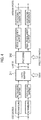
- Fig. 4 is a block diagram of the processor 240 related to the downlink multi-antenna transmission. The details of each block are described in 3GPP TS 36.211, for example. However, an overview of each block will be described herein.
- one or two codewords to be transmitted on a physical channel are scrambled, are modulated into a modulation symbol, and then are mapped to a plurality of layers by a layer mapper 241.
- the codeword is an error correction data unit.
- the rank (number of layers) is determined on the basis of the RI that is fed back.
- a precoder 242 precodes a modulation symbol of each layer by using the precoder matrix.
- the precoder matrix is determined on the basis of the PMI that is fed back.
- the precoded modulation symbol is mapped to a resource element, is converted into an OFDM signal of a temporal domain, and is output to each antenna port.
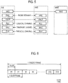
- Fig. 5 is a protocol stack diagram of a radio interface in the LTE system.
- the radio interface protocol is classified into a layer 1 to a layer 3 of an OSI reference model, wherein the layer 1 is a physical (PHY) layer.
- the layer 2 includes a MAC (Medium Access Control) layer, an RLC (Radio Link Control) layer, and a PDCP (Packet Data Convergence Protocol) layer.
- the layer 3 includes an RRC (Radio Resource Control) layer.
- the PHY layer performs encoding and decoding, modulation and demodulation, antenna mapping and demapping, and resource mapping and demapping. Between the PHY layer of the UE 100 and the PHY layer of the eNB 200, data is transmitted via the physical channel.
- the MAC layer performs preferential control of data, and a retransmission process by hybrid ARQ (an HARQ) and the like. Between the MAC layer of the UE 100 and the MAC layer of the eNB 200, data is transmitted via a transport channel.
- the MAC layer of the eNB 200 includes a MAC scheduler that determines an uplink and downlink transport format (a transport block size, a modulation and coding scheme and the like) and an allocation resource block.
- the RLC layer transmits data to an RLC layer of a reception side by using the functions of the MAC layer and the PHY layer. Between the RLC layer of the UE 100 and the RLC layer of the eNB 200, data is transmitted via a logical channel.
- the PDCP layer performs header compression and decompression, and encryption and decryption.
- the RRC layer is defined only in a control plane. Between the RRC layer of the UE 100 and the RRC layer of the eNB 200, a control message (an RRC message) for various types of setting is transmitted.
- the RRC layer controls the logical channel, the transport channel, and the physical channel in response to establishment, re-establishment, and release of a radio bearer.
- an RRC connection is established between the RRC of the UE 100 and the RRC of the eNB 200, the UE 100 is in a connection state (a RRC Connected state), and when the RRC connection is not established, the UE 100 is in an idle state (a RRC Idle state).
- a NAS (Non-Access Stratum) layer positioned above the RRC layer performs session management or mobility management, for example.
- Fig. 6 is a configuration diagram of a radio frame used in the LTE system.
- OFDMA Orthogonal Frequency Division Multiple Access
- SC-FDMA Single Carrier Frequency Division Multiple Access
- duplex scheme either an FDD (Frequency Division Duplex) scheme or a TDD (Time Division Duplex) scheme is used.
- FDD Frequency Division Duplex
- TDD Time Division Duplex
- the FDD scheme is mainly assumed.
- the radio frame is configured by 10 subframes arranged in a time direction, wherein each subframe is configured by two slots arranged in the time direction.
- Each subframe has a length of 1 ms and each slot has a length of 0.5 ms.
- Each subframe includes a plurality of resource blocks (RBs) in a frequency direction, and a plurality of symbols in the time direction. Each symbol is provided at a head thereof with a guard interval called a cyclic prefix (CP).
- the resource block includes a plurality of subcarriers in the frequency direction.
- a radio resource unit configured by one subcarrier and one symbol is called a resource element (RE).
- RE resource element
- a frequency resource can be designated by a resource block and a time resource can be designated by a subframe (or slot).
- an interval of several symbols at the head of each subframe is a control region mainly used as a physical downlink control channel (PDCCH). Furthermore, the other interval of each subframe is a region mainly used as a physical downlink shared channel (PDSCH). Furthermore, a reference signal such as a cell-specific reference signal (CRS) is distributed and arranged in each subframe.
- a reference signal such as a cell-specific reference signal (CRS) is distributed and arranged in each subframe.
- the PDCCH carries control information.
- the control information for example, includes the uplink SI (Scheduling Information), the downlink SI, and a TPC bit.
- the uplink SI is information indicating the allocation of uplink radio resources
- the downlink SI is information indicating the allocation of downlink radio resources.
- the TPC bit is information for instructing an increase or decrease in the uplink transmission power.
- the PDSCH carries the control information and/or user data.
- a downlink data region may be allocated only to the user data, or may be allocated such that the user data and the control information are multiplexed.
- both end portions in the frequency direction of each subframe are control regions mainly used as a physical uplink control channel (PUCCH). Furthermore, the center portion, in the frequency direction, of each subframe is a region mainly used as a physical uplink shared channel (PUSCH).
- PUCCH physical uplink control channel
- PUSCH physical uplink shared channel
- the PUCCH carries control information.
- the control information includes, for example, the CQI, the PMI, the RI, SR (Scheduling Request), and ACK/NACK.
- the CQI indicates a modulation and coding scheme (that is, a recommended MCS) that is preferably used in the downlink, on the basis of the reception status of the downlink.
- a modulation and coding scheme that is, a recommended MCS
- the PMI is information indicating a precoder matrix that is preferably used in the downlink.
- the PMI is information indicating a precoder matrix in which a beam is directed toward the UE serving as a transmission source of the PMI.
- the UE 100 selects the PMI to be fed back to the eNB 200.
- the RI indicates a rank that is preferably used in the downlink. For example, in order for the rank corresponding to the reception status of the UE 100 to be applied, the UE 100 selects the PMI to be fed back to the eNB 200.
- the SR is information for requesting the allocation of uplink radio resources.
- the ACK/NACK is information indicating whether or not the decoding of a signal transmitted via a downlink physical channel (for example, PDSCH) is successful.
- the PUSCH is a physical channel that carries the control information and/or user data.
- an uplink data region may be allocated only to the user data, or may be allocated such that the user data and the control information are multiplexed.
- Fig. 7 is an explanatory diagram for describing an operation overview according to the present embodiment.
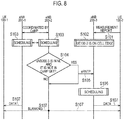
- Fig. 8 is a sequence diagram for describing an operation sequence according to the present embodiment.
- the mobile communication system has a UE 100-1, a UE 100-2, a UE 100-3, an eNB 200-1, an eNB 200-2, and an eNB 200-3.
- the eNB 200-1 and the eNB 200-2 are included in a CoMP coordinating set and perform CoMP communication with the UE 100-1.
- the eNB 200-1 and the eNB 200-2 perform CoMP communication of a DPS (Dynamic Point Selection) scheme in which a plurality of points selectively perform transmission to a user terminal with securing the same radio resource.
- the eNB 200-3 performs normal communication with the UE 100-2 and the UE 100-3 that are subordinate of a cell managed by the eNB 200-3. That is, the eNB 200-3 is not included in the CoMP coordinating set.
- the UE 100-2 is located at the edge of the cell of the eNB 200-3, and the UE 100-3 is located near the center of the cell of the eNB 200-3.
- step S101 the UE 100-2 transmits, to the eNB 200-3, a measurement report in which a reception state (received power and/or reception quality) of a reference signal from the eNB 200 is measured.
- the eNB 200-3 receives the measurement report from the UE 100-2.
- the eNB 200-3 determines, on the basis of the measurement report, whether or not the UE 100-2 is located at the edge of a cell managed by the eNB 200-3 (on the eNB 200-2 side). For example, when the received power from the eNB 200-2 is equal to or more than a predetermined value, the eNB 200-3 determines that the UE 100-2 is located at the edge of the cell of the eNB 200-3 on the eNB 200-2 side. In the present embodiment, description will be given on an assumption that the eNB 200-3 determines that the UE 100-2 is located at the edge of the cell of the eNB 200-3 on the eNB 200-2 side.
- each of the eNB 200-1 and the eNB 200-2 performs scheduling for allocating a radio resource to a UE 100 that is a subordinate of the eNB 200-1 and the eNB 200-2. Furthermore, the eNB 200-1 and the eNB 200-2 exchange scheduling information that is allocation information of the allocated radio resource. As a result, each of the eNB 200-1 and the eNB 200-2 secures the same radio resource used for the CoMP communication (hereinafter, referred to as CoMP communication resource).
- step S104 the eNB 200-2 searches, on the basis of a neighboring cell list on a neighboring eNB 200 that exists around the eNB 200-2, an eNB 200 that is a neighboring eNB 200 of the eNB 200-2 and is not included in the CoMP coordinating set with the eNB 200-2.
- the eNB 200-2 records, on the neighboring cell list, not only a neighboring eNB 200 of the eNB 200-2 but also an eNB 200 performing CoMP communication with the eNB 200-2.
- the eNB 200-2 determines, on the basis of the neighboring cell list on which an eNB 200 performing CoMP communication with the eNB 200-2 is recorded, whether or not the eNB 200-3 is a neighboring eNB 200 and whether or not the eNB 200-3 is included in the CoMP coordinating set.
- the CoMP coordinating set in this case may be an eNB 200 that is a target of coordinated transmission with the eNB 200-2 and may be an eNB 200 that currently performs coordinated transmission with the eNB 200-2, for example.
- description will be given such that the eNB 200-2 regards an eNB 200 that currently performs coordinated transmission with the eNB 200-2 as the CoMP coordinating set.
- the eNB 200-2 executes the process in step S105.
- the eNB 200-2 executes the process in step S107.
- description will be given on an assumption that the eNB 200-2 determines that the eNB 200-3 is a neighboring eNB 200 and is not included in the CoMP coordinating set.
- step S105 the eNB 200-2 transmits, to the eNB 200-3, transmission power information concerning transmission power of the eNB 200-2 corresponding to at least the CoMP communication resource.
- the eNB 200-3 receives the transmission power information.
- the transmission power information is eRNTP.
- the eRNTP includes restriction information indicating restriction on downlink transmission power of the eNB 200-2 for each resource block, and subframe information indicating a subframe concerning the restriction information.
- the subframe information includes information indicating a subframe in which at least the CoMP communication resource is located.
- the restriction information includes information indicating a radio resource of which transmission power is equal to zero.
- the subframe information is, for example, as shown in Fig. 9 , information specifying a single subframe in which the eRNTP is effective.
- the subframe information may be information specifying a range of subframe in which the eRNTP is effective.
- IE may be divided into a subframe start and a subframe end.
- the subframe information may be information specifying a subframe period during which the eRNTP is effective.
- the subframe information may be information specifying a subframe start and a subframe period
- the subframe information may be information specifying a subframe denominator (subframe modulo) and a subframe of which a subframe number that can be divided by the subframe denominator is determined as a subframe in which the eRNTP is effective
- the subframe information may be information specifying a subframe offset.
- the subframe information may be information formed by combining (a) to (c), and the eNB 200-2 may transmit each of the information of (a) to (c).
- the eNB 200-2 when the eNB 200-2 performs CS-CoMP communication in which semi-persistent scheduling (SPS) is performed, the eNB 200-2 is capable of transmitting, as the subframe information, the information specifying a subframe period during which the eRNTP is effective. It is noted that in the CS (Coordinated Scheduling)-CoMP communication, coordinated scheduling is performed among each eNB 200 that is included in the CoMP coordinating set.
- SPS semi-persistent scheduling
- step S106 the eNB 200-3 performs scheduling on the basis of the transmission power information.
- the eNB 200-3 allocates a radio resource corresponding to the CoMP communication resource, to the UE 100-2, the UE 100-2 being determined to be located at the edge of the cell of the eNB 200-3 on the eNB 200-2 side. Specifically, the eNB 200-3 allocates, to the UE 100-2, a radio resource of which the transmission power of the eNB 200-2 is equal to zero.
- step S107 the eNB 200-1 and the eNB 200-2 perform communication with the UE 100-1 by the CoMP communication. Specifically, only the eNB 200-1 transmits data to the UE 100-1 by using the CoMP communication resource, and the eNB 200-2 does not perform transmission by using the CoMP communication resource. On the other hand, the eNB 200-3 transmits data to the UE 100-2 by using the radio resource corresponding to the CoMP communication resource.
- the eNB 200-2 secures the same radio resource as the CoMP communication resource that the eNB 200-1 secures for the coordinated communication.
- the eNB 200-2 transmits, to the eNB 200-3, the transmission power information concerning the transmission power of the eNB 200-2 corresponding to at least the CoMP communication resource.
- the eNB 200-3 receives the transmission power information from the eNB 200-2.
- the eNB 200-3 allocates a radio resource to the UE 100-2 on the basis of the transmission power information.
- the eNB 200-2 is capable of recognizing the radio resource corresponding to the CoMP communication resource of which the transmission power is regulated, and thus, the eNB 200-3 takes the CoMP communication resource into consideration, then the eNB 200-3 is capable of allocating a radio resource to the UE 100-2 such that the interference from the eNB 200-2 to the UE 100-2 can be suppressed.
- the eNB 200-3 that is not included in the CoMP coordinating set actively utilizes the radio resource corresponding to the CoMP communication resource, then a throughput in the eNB 200-3 is improved, and thus, it is possible to improve the system capacity.
- the eNB 200-2 when the eNB 200-1 performs transmission to the UE 100-1 by using the CoMP communication resource, to the UE 100-1, the eNB 200-2 transmits, to the eNB 200-3, as the transmission power information, information indicating that the transmission power of the eNB 200-2 is equal to zero.
- the eNB 200-3 receives the transmission power information.
- the UE 100-2 receives an interference from the eNB 200-2 (specifically, when the received power from the eNB 200-2 is equal to or more than a predetermined value)
- the eNB 200-3 allocates, to the UE 100-2, a radio resource corresponding to the CoMP communication resource.
- the interference from the eNB 200-2 to the UE 100-2 can be suppressed, and thus, a throughput in the eNB 200-3 improves, then it is possible to improve the system capacity.
- the transmission power information includes information indicating restriction on transmission power of the eNB 200-2 for each resource block, and information indicating a subframe in which at least the CoMP communication resource is located.
- the eNB 200-2 is capable of allocating a radio resource to the UE 100-2 on the basis of the information indicating the subframe.
- the eNB 200-2 is capable of recognizing the subframe in which the CoMP communication resource is located, and thus, it is possible to appropriately allocate, to the UE 100-2, a radio resource corresponding to the CoMP communication resource.
- the eNB 200-2 records, on the neighboring cell list, an eNB 200 performing the CoMP communication with the eNB 200-2.
- the eNB 200-2 transmits the transmission power information to the eNB 200-3 on the basis of the neighboring cell list.
- the eNB 200-2 is capable of restraining from transmitting the transmission power information to an eNB 200 that is not a neighboring eNB 200 of the eNB 200-2 or to an eNB 200 performing the CoMP communication with the eNB 200-2.
- the eNB 200-2 is capable of restraining from transmitting unnecessary information to another eNB 200, and thus, it is possible to improve the system capacity.
- the eNB 200-3 when determining that the UE 100-2 is located at the edge of the cell of the eNB 200-3 on the eNB 200-2 side, the eNB 200-3 allocates, to the UE 100-2, a radio resource corresponding to the CoMP communication resource.
- the radio resource corresponding to the CoMP communication resource can be allocated to a UE 100 that easily receives an interference from the eNB 200-2, and thus, it is possible to obtain an effect of effective interference containment.
- the eNB 200-1 and the eNB 200-2 perform the CoMP communication of the DPS scheme (DPS-CoMP); however, in the present modification, the eNB 200-1 and the eNB 200-2 perform JT-CoMP in which a plurality of points simultaneously perform transmission to a UE 100 by using the same radio resource.
- DPS-CoMP DPS scheme
- JT-CoMP JT-CoMP in which a plurality of points simultaneously perform transmission to a UE 100 by using the same radio resource.
- the eNB 200-1 and the eNB 200-2 decide to reduce the transmission power.
- Each of the eNB 200-1 and the eNB 200-2 decides to perform the JT-CoMP by reducing the transmission power by a predetermined value (for example, 3 dB).
- the eNB 200-2 transmits, to the eNB 200-3, as the transmission power information, information indicating the predetermined value and the CoMP communication resource of which the transmission power is reduced.
- the eNB 200-3 allocates, on the basis of the received transmission power information, a radio resource corresponding to the CoMP communication resource, to the UE 100-2.
- the eNB 200-1 and the eNB 200-2 transmit data to the UE 100-1 by using the CoMP communication resource.
- the eNB 200-3 transmits data to the UE 100-2 by using the radio resource corresponding to the CoMP communication resource.
- the transmission power from the eNB 200-2 is reduced in the radio resource, and thus, the interference from the eNB 200-2 received in the UE 100-2 is reduced. Consequently, a throughput in the eNB 200-3 improves, and thus, it is possible to improve the system capacity.
- the information indicating restriction on the transmission power for each resource block is transmitted as the transmission power information.
- the transmission power information is information concerning increase in transmission power.
- the eNB 200-1 decides to increase transmission power corresponding to the CoMP communication resource.
- the eNB 200-1 transmits, as the transmission power information, the information concerning increase in transmission power, to an eNB 200-4 (not shown in the figure) that is a neighboring eNB 200 of the eNB 200-1 and that does not perform the CoMP communication with the eNB 200-1.
- the information concerning increase in transmission power is information indicating increase in transmission power of the eNB 200-1 for each resource block.
- the eNB 200-4 receives the transmission power information, and allocates, on the basis of the transmission power information, a radio resource different from the radio resource corresponding to the CoMP communication resource, to a UE 100 that receives an interference from the eNB 200-1.
- the eNB 200-4 is capable of performing allocation to a UE 100 by avoiding a radio resource that receives the interference from the eNB 200-1, and thus, a throughput in the eNB 200-4 is improved. Consequently, it is possible to improve the system capacity.
- the eNB 200-2 may transmit transmission power information concerning transmission power of the eNB 200-2 corresponding to only the CoMP communication resource. Furthermore, the eNB 200-2 may transmit, as the transmission power information, information indicating an ABS (Almost Blank Subframe), not the eRNTP.
- the eNB 200-3 determines, on the basis of the measurement report, whether or not the UE 100-2 is located at the edge of the cell on the eNB 200-2 side; however, this is not limiting.
- the eNB 200-3 may make such a determination on the basis of location information of the UE 100-2, for example.
- the eNB 200-3 may transmit, to the UE 100-2, setting information for transmitting a measurement report in which the eNB 200-2 and the eNB 200-3 are regarded as a CoMP coordinating set.
- a measurement target is usually a cell-specific reference signal (CRS: Cell-specific RS) as a radio signal from a neighboring cell (eNB 200-2); however, a channel-state-information reference signal (CSI-RS: Channel State Information RS) becomes the measurement target.
- CRS Cell-specific RS
- CSI-RS Channel State Information RS
- the eNB 200-3 is capable of transmitting the setting information to the UE 100-2, even though the eNB 200-2 and the eNB 200-3 are not included in the CoMP coordinating set. As a result, the eNB 200-3 receives, from the UE 100-2, the measurement report in which the measurement target is the CSI-RS, and thus, it is possible to decide an accurate MCS for the UE 100-2, in which an interference from the eNB 200-2 is considered. It is noted that even when not receiving the measurement report in which the measurement target is the CSI-RS of the eNB 200-2, the eNB 200-3 may readily decide an MCS for the UE 100-2, on the basis of RSRP of the eNB 200-2 obtained by a normal measurement report. As a result, it is possible to improve the system capacity.
- the eNB 200-2 records an eNB 200 performing the CoMP communication with the eNB 200-2 on the neighboring cell list; however, an eNB 200 performing the CoMP communication with the eNB 200-2 may be recorded on a list different from the neighboring cell list.
- the eNB 200-2 may transmit the transmission power information to an eNB 200 recorded on the neighboring cell list, without determining whether or not the eNB 200 is included in the CoMP coordinating set with the eNB 200-2.
- the eNB 200-2 and the eNB 200-3 are in a relationship of a neighboring eNB 200 with each other, and a cell managed by the eNB 200-2 (hereinafter, referred to as second cell, where necessary) and a cell managed by the eNB 200-3 (hereinafter, referred to as third cell, where necessary) are adjacent; however, this is not limiting.
- the eNB 200-3 may be installed within the second cell and the third cell may be a cell having a smaller coverage than that of the second cell. Therefore, the eNB 200-2 may be an eNB 200 that manages a macro cell, and the eNB 200-3 may be an eNB 200 that manages a pico cell or a femto cell.
- the eNB 200-3 when the eNB 200-3 supports a dual connectivity scheme in which two eNBs 200 establish connection (RRC connection/data path) with the same UE 100, and when dual connectivity with the same UE 100 is available for the eNB 200-2 and the eNB 200-3, the eNB 200-2 may transmit the transmission power information to the eNB 200-3.
- the eNB 200-3 is capable of allocating, on the basis of the transmission power information, a radio resource corresponding to the CoMP communication resource (or a radio resource different from the radio resource corresponding to the CoMP communication resource) to the UE 100 with which the dual connectivity is performed.
- the eNB 200-2 transmits the transmission power information to the neighboring eNB 200; however, this is not limiting. For example, among from a plurality of UEs 100 performing D2D communication that is direct device-to-device communication, the eNB 200-2 may transmit the transmission power information to a scheduling UE that performs allocation of a radio resource used in the D2D communication.
- the eNB 200-2 may transmit the transmission power information to a scheduling UE located within the second cell, or the eNB 200-2 may transmit, via the eNB 200-3, the transmission power information to a scheduling UE located within the third cell.
- the scheduling UE is capable of allocating, on the basis of the transmission power information, a radio resource corresponding to the CoMP communication resource (or a radio resource different from the radio resource corresponding to the CoMP communication resource) to a UE 100 that configures a group to which the scheduling UE belongs.
- the UE 100 to which the radio resource is allocated performs the D2D communication by using the radio resource.
- the scheduling UE is capable of executing a similar operation with the eNB 200-3 according to the above-described embodiment (see Fig. 8 ). It is noted that in this case, operations in the above-described step S101 and step S102 may be omitted.
- the operation in step S107 may be an operation of the scheduling UE or may be an operation of the UE 100 to which the radio resource is allocated.
- the base station according to the present invention possible to increase system capacity when CoMP communication is performed, thus they are useful in the mobile communication field.
Landscapes
- Engineering & Computer Science (AREA)
- Computer Networks & Wireless Communication (AREA)
- Signal Processing (AREA)
- Quality & Reliability (AREA)
- Mobile Radio Communication Systems (AREA)
Claims (2)
- Basisstation (200-2), die eine koordinierte Mehrpunktkommunikation (coordinated Multi-Point, CoMP) mit einem Benutzerendgerät (100) ausführt, umfassend:einen Sender (201, 210), der konfiguriert ist, um Sendeleistungsinformationen an eine benachbarte Basisstation (200-3) zu senden, die eine Beschränkung einer Downlink-Sendeleistung der Basisstation (200-2) in der CoMP-Kommunikation angeben,wobei die Sendeleistungsinformationen Folgendes umfassen:einen Schwellenwert;eine Bitfolge, die für jeden Ressourcenblock angibt, ob die Downlink-Sendeleistung den Schwellenwert überschreitet; undeine Start-Subrahmennummer, bei der die durch die Bitfolge angegebene Beschränkung gültig wird,wobei die Sendeleistungsinformationen konfiguriert sind, um die benachbarte Basisstation (200-3) zu veranlassen, bei Empfangen der Sendeleistungsinformation eine Planung auszuführen, dadurch gekennzeichnet, dassdie Sendeleistungsinformationen ferner Subrahmen-Periodeninformationen umfassen, die eine Periode von Subrahmen angeben, über die die Frequenzbereichsbeschränkung aktiv ist, einschließlich der Start-Subrahmennummer.
- Basisstation (200-3), umfassend:
einen Empfänger (201, 210), der konfiguriert ist, um von einer benachbarten Basisstation (200-2), die eine koordinierte Mehrpunktkommunikation (CoMP-Kommunikation) mit einem Benutzerendgerät (100) ausführt, Sendeleistungsinformationen zu empfangen, die eine Beschränkung der Downlink-Sendeleistung der benachbarten Basisstation (200-2) in der CoMP-Kommunikation angeben, wobei die Sendeleistungsinformationen Folgendes umfassen:einen Schwellenwert;eine Bitfolge, die für jeden Ressourcenblock angibt, ob die Downlink-Sendeleistung den Schwellenwert überschreitet; undeine Start-Subrahmennummer, bei der die durch die Bitfolge angegebene Beschränkung gültig wird,eine Steuerung (240), die konfiguriert ist, um eine Planung auf der Grundlage der Sendeleistungsinformationen auszuführen, wobei die Steuerung (240) bestimmt, dass die Beschränkung ab dem Start-Subrahmen gültig wird,dadurch gekennzeichnet, dassdie Sendeleistungsinformationen ferner Subrahmen-Periodeninformationen umfassen, die eine Periode von Subrahmen angeben, über die die Frequenzbereichsbeschränkung aktiv ist, einschließlich der Start-Subrahmennummer.
Applications Claiming Priority (2)
| Application Number | Priority Date | Filing Date | Title |
|---|---|---|---|
| JP2013224773 | 2013-10-29 | ||
| PCT/JP2014/078243 WO2015064476A1 (ja) | 2013-10-29 | 2014-10-23 | 基地局 |
Publications (3)
| Publication Number | Publication Date |
|---|---|
| EP3065458A1 EP3065458A1 (de) | 2016-09-07 |
| EP3065458A4 EP3065458A4 (de) | 2017-05-17 |
| EP3065458B1 true EP3065458B1 (de) | 2019-09-11 |
Family
ID=53004082
Family Applications (1)
| Application Number | Title | Priority Date | Filing Date |
|---|---|---|---|
| EP14858572.2A Active EP3065458B1 (de) | 2013-10-29 | 2014-10-23 | Basisstation |
Country Status (4)
| Country | Link |
|---|---|
| US (1) | US9888447B2 (de) |
| EP (1) | EP3065458B1 (de) |
| JP (1) | JPWO2015064476A1 (de) |
| WO (1) | WO2015064476A1 (de) |
Families Citing this family (2)
| Publication number | Priority date | Publication date | Assignee | Title |
|---|---|---|---|---|
| US10148395B2 (en) * | 2014-08-07 | 2018-12-04 | Nec Corporation | Radio communication system, control device, base station, information transmitting method, and information receiving method |
| US11026186B2 (en) * | 2017-10-27 | 2021-06-01 | Qualcomm Incorporated | Power control for concurrent reception |
Family Cites Families (11)
| Publication number | Priority date | Publication date | Assignee | Title |
|---|---|---|---|---|
| US8260206B2 (en) * | 2008-04-16 | 2012-09-04 | Qualcomm Incorporated | Methods and apparatus for uplink and downlink inter-cell interference coordination |
| KR101547545B1 (ko) * | 2009-04-20 | 2015-09-04 | 삼성전자주식회사 | 무선 통신 시스템의 기지국간 간섭 제거를 위한 방법 및 이를 위한 장치 |
| EP2498410B1 (de) * | 2009-10-30 | 2013-10-23 | Fujitsu Limited | Basisstation und Kommunikationsverfahren |
| CN102696256B (zh) * | 2010-01-08 | 2016-12-07 | 太阳专利信托公司 | 通信装置及通信方法 |
| CN102685864B (zh) * | 2011-03-11 | 2017-03-01 | 夏普株式会社 | 通信方法及应用该通信方法的基站 |
| WO2013062362A1 (ko) * | 2011-10-26 | 2013-05-02 | 엘지전자 주식회사 | 무선 통신 시스템에서 셀간 간섭 조정 방법 및 장치 |
| JP2013126154A (ja) * | 2011-12-15 | 2013-06-24 | Panasonic Corp | 基地局及び基地局の協調方法 |
| CN104137435B (zh) * | 2012-02-29 | 2018-03-27 | Lg电子株式会社 | 在协作多小区无线通信系统中减小小区间干扰的方法及设备 |
| US9526091B2 (en) * | 2012-03-16 | 2016-12-20 | Intel Corporation | Method and apparatus for coordination of self-optimization functions in a wireless network |
| JP5928123B2 (ja) | 2012-04-20 | 2016-06-01 | ダイキン工業株式会社 | 空気調和装置 |
| WO2014046399A1 (ko) * | 2012-09-21 | 2014-03-27 | 엘지전자 주식회사 | 무선 통신 시스템에서 주파수 도메인에서 제한적 측정 방법 및 이를 위한 장치 |
-
2014
- 2014-10-23 WO PCT/JP2014/078243 patent/WO2015064476A1/ja active Application Filing
- 2014-10-23 JP JP2015544958A patent/JPWO2015064476A1/ja active Pending
- 2014-10-23 EP EP14858572.2A patent/EP3065458B1/de active Active
-
2016
- 2016-04-27 US US15/139,849 patent/US9888447B2/en active Active
Non-Patent Citations (1)
| Title |
|---|
| None * |
Also Published As
| Publication number | Publication date |
|---|---|
| WO2015064476A1 (ja) | 2015-05-07 |
| US20160242126A1 (en) | 2016-08-18 |
| US9888447B2 (en) | 2018-02-06 |
| EP3065458A1 (de) | 2016-09-07 |
| JPWO2015064476A1 (ja) | 2017-03-09 |
| EP3065458A4 (de) | 2017-05-17 |
Similar Documents
| Publication | Publication Date | Title |
|---|---|---|
| JP6140043B2 (ja) | ユーザ端末、基地局、及びプロセッサ | |
| WO2014084029A1 (ja) | 基地局、プロセッサ、通信制御方法及びユーザ端末 | |
| JP6143524B2 (ja) | 移動通信システム、無線基地局及びユーザ端末 | |
| US9923689B2 (en) | Mobile communication system, user terminal, and processor for assigning radio resources for transmission of sounding reference signals and device to device communication resources | |
| WO2014050557A1 (ja) | 移動通信システム、基地局及びユーザ端末 | |
| US20160021676A1 (en) | Base station and communication control method | |
| JP6352280B2 (ja) | ネットワーク装置及びユーザ端末 | |
| US20150304003A1 (en) | Mobile communication system, user terminal, and processor | |
| JP6158309B2 (ja) | 基地局、プロセッサ、及び通信制御方法 | |
| JP6453760B2 (ja) | 通信制御方法及び基地局 | |
| US9866342B2 (en) | Mobile communication system, communication control method, base station, user terminal and processor | |
| US9888447B2 (en) | Base station | |
| JP6134329B2 (ja) | 移動通信システム、ユーザ端末、及びプロセッサ | |
| JP6034956B2 (ja) | 移動通信システム、基地局及びユーザ端末 | |
| JP6216026B2 (ja) | 基地局及びプロセッサ | |
| WO2015046101A1 (ja) | ユーザ端末、プロセッサ、及び通信制御方法 |
Legal Events
| Date | Code | Title | Description |
|---|---|---|---|
| PUAI | Public reference made under article 153(3) epc to a published international application that has entered the european phase |
Free format text: ORIGINAL CODE: 0009012 |
|
| 17P | Request for examination filed |
Effective date: 20160524 |
|
| AK | Designated contracting states |
Kind code of ref document: A1 Designated state(s): AL AT BE BG CH CY CZ DE DK EE ES FI FR GB GR HR HU IE IS IT LI LT LU LV MC MK MT NL NO PL PT RO RS SE SI SK SM TR |
|
| AX | Request for extension of the european patent |
Extension state: BA ME |
|
| DAX | Request for extension of the european patent (deleted) | ||
| A4 | Supplementary search report drawn up and despatched |
Effective date: 20170420 |
|
| RIC1 | Information provided on ipc code assigned before grant |
Ipc: H04W 52/46 20090101ALI20170412BHEP Ipc: H04W 52/40 20090101ALI20170412BHEP Ipc: H04W 28/16 20090101AFI20170412BHEP Ipc: H04W 52/28 20090101ALI20170412BHEP Ipc: H04W 16/28 20090101ALI20170412BHEP Ipc: H04W 52/54 20090101ALI20170412BHEP Ipc: H04W 92/20 20090101ALI20170412BHEP Ipc: H04W 52/24 20090101ALI20170412BHEP Ipc: H04W 52/34 20090101ALI20170412BHEP |
|
| STAA | Information on the status of an ep patent application or granted ep patent |
Free format text: STATUS: EXAMINATION IS IN PROGRESS |
|
| 17Q | First examination report despatched |
Effective date: 20180228 |
|
| GRAP | Despatch of communication of intention to grant a patent |
Free format text: ORIGINAL CODE: EPIDOSNIGR1 |
|
| STAA | Information on the status of an ep patent application or granted ep patent |
Free format text: STATUS: GRANT OF PATENT IS INTENDED |
|
| INTG | Intention to grant announced |
Effective date: 20190510 |
|
| GRAS | Grant fee paid |
Free format text: ORIGINAL CODE: EPIDOSNIGR3 |
|
| GRAA | (expected) grant |
Free format text: ORIGINAL CODE: 0009210 |
|
| STAA | Information on the status of an ep patent application or granted ep patent |
Free format text: STATUS: THE PATENT HAS BEEN GRANTED |
|
| AK | Designated contracting states |
Kind code of ref document: B1 Designated state(s): AL AT BE BG CH CY CZ DE DK EE ES FI FR GB GR HR HU IE IS IT LI LT LU LV MC MK MT NL NO PL PT RO RS SE SI SK SM TR |
|
| REG | Reference to a national code |
Ref country code: GB Ref legal event code: FG4D |
|
| REG | Reference to a national code |
Ref country code: CH Ref legal event code: EP |
|
| REG | Reference to a national code |
Ref country code: AT Ref legal event code: REF Ref document number: 1180094 Country of ref document: AT Kind code of ref document: T Effective date: 20190915 |
|
| REG | Reference to a national code |
Ref country code: DE Ref legal event code: R096 Ref document number: 602014053629 Country of ref document: DE Ref country code: IE Ref legal event code: FG4D |
|
| REG | Reference to a national code |
Ref country code: NL Ref legal event code: MP Effective date: 20190911 |
|
| REG | Reference to a national code |
Ref country code: LT Ref legal event code: MG4D |
|
| PG25 | Lapsed in a contracting state [announced via postgrant information from national office to epo] |
Ref country code: FI Free format text: LAPSE BECAUSE OF FAILURE TO SUBMIT A TRANSLATION OF THE DESCRIPTION OR TO PAY THE FEE WITHIN THE PRESCRIBED TIME-LIMIT Effective date: 20190911 Ref country code: BG Free format text: LAPSE BECAUSE OF FAILURE TO SUBMIT A TRANSLATION OF THE DESCRIPTION OR TO PAY THE FEE WITHIN THE PRESCRIBED TIME-LIMIT Effective date: 20191211 Ref country code: SE Free format text: LAPSE BECAUSE OF FAILURE TO SUBMIT A TRANSLATION OF THE DESCRIPTION OR TO PAY THE FEE WITHIN THE PRESCRIBED TIME-LIMIT Effective date: 20190911 Ref country code: NO Free format text: LAPSE BECAUSE OF FAILURE TO SUBMIT A TRANSLATION OF THE DESCRIPTION OR TO PAY THE FEE WITHIN THE PRESCRIBED TIME-LIMIT Effective date: 20191211 Ref country code: LT Free format text: LAPSE BECAUSE OF FAILURE TO SUBMIT A TRANSLATION OF THE DESCRIPTION OR TO PAY THE FEE WITHIN THE PRESCRIBED TIME-LIMIT Effective date: 20190911 Ref country code: HR Free format text: LAPSE BECAUSE OF FAILURE TO SUBMIT A TRANSLATION OF THE DESCRIPTION OR TO PAY THE FEE WITHIN THE PRESCRIBED TIME-LIMIT Effective date: 20190911 |
|
| PG25 | Lapsed in a contracting state [announced via postgrant information from national office to epo] |
Ref country code: RS Free format text: LAPSE BECAUSE OF FAILURE TO SUBMIT A TRANSLATION OF THE DESCRIPTION OR TO PAY THE FEE WITHIN THE PRESCRIBED TIME-LIMIT Effective date: 20190911 Ref country code: LV Free format text: LAPSE BECAUSE OF FAILURE TO SUBMIT A TRANSLATION OF THE DESCRIPTION OR TO PAY THE FEE WITHIN THE PRESCRIBED TIME-LIMIT Effective date: 20190911 Ref country code: GR Free format text: LAPSE BECAUSE OF FAILURE TO SUBMIT A TRANSLATION OF THE DESCRIPTION OR TO PAY THE FEE WITHIN THE PRESCRIBED TIME-LIMIT Effective date: 20191212 Ref country code: AL Free format text: LAPSE BECAUSE OF FAILURE TO SUBMIT A TRANSLATION OF THE DESCRIPTION OR TO PAY THE FEE WITHIN THE PRESCRIBED TIME-LIMIT Effective date: 20190911 Ref country code: ES Free format text: LAPSE BECAUSE OF FAILURE TO SUBMIT A TRANSLATION OF THE DESCRIPTION OR TO PAY THE FEE WITHIN THE PRESCRIBED TIME-LIMIT Effective date: 20190911 |
|
| REG | Reference to a national code |
Ref country code: AT Ref legal event code: MK05 Ref document number: 1180094 Country of ref document: AT Kind code of ref document: T Effective date: 20190911 |
|
| PG25 | Lapsed in a contracting state [announced via postgrant information from national office to epo] |
Ref country code: IT Free format text: LAPSE BECAUSE OF FAILURE TO SUBMIT A TRANSLATION OF THE DESCRIPTION OR TO PAY THE FEE WITHIN THE PRESCRIBED TIME-LIMIT Effective date: 20190911 Ref country code: EE Free format text: LAPSE BECAUSE OF FAILURE TO SUBMIT A TRANSLATION OF THE DESCRIPTION OR TO PAY THE FEE WITHIN THE PRESCRIBED TIME-LIMIT Effective date: 20190911 Ref country code: AT Free format text: LAPSE BECAUSE OF FAILURE TO SUBMIT A TRANSLATION OF THE DESCRIPTION OR TO PAY THE FEE WITHIN THE PRESCRIBED TIME-LIMIT Effective date: 20190911 Ref country code: PL Free format text: LAPSE BECAUSE OF FAILURE TO SUBMIT A TRANSLATION OF THE DESCRIPTION OR TO PAY THE FEE WITHIN THE PRESCRIBED TIME-LIMIT Effective date: 20190911 Ref country code: RO Free format text: LAPSE BECAUSE OF FAILURE TO SUBMIT A TRANSLATION OF THE DESCRIPTION OR TO PAY THE FEE WITHIN THE PRESCRIBED TIME-LIMIT Effective date: 20190911 Ref country code: PT Free format text: LAPSE BECAUSE OF FAILURE TO SUBMIT A TRANSLATION OF THE DESCRIPTION OR TO PAY THE FEE WITHIN THE PRESCRIBED TIME-LIMIT Effective date: 20200113 Ref country code: NL Free format text: LAPSE BECAUSE OF FAILURE TO SUBMIT A TRANSLATION OF THE DESCRIPTION OR TO PAY THE FEE WITHIN THE PRESCRIBED TIME-LIMIT Effective date: 20190911 |
|
| PG25 | Lapsed in a contracting state [announced via postgrant information from national office to epo] |
Ref country code: CZ Free format text: LAPSE BECAUSE OF FAILURE TO SUBMIT A TRANSLATION OF THE DESCRIPTION OR TO PAY THE FEE WITHIN THE PRESCRIBED TIME-LIMIT Effective date: 20190911 Ref country code: IS Free format text: LAPSE BECAUSE OF FAILURE TO SUBMIT A TRANSLATION OF THE DESCRIPTION OR TO PAY THE FEE WITHIN THE PRESCRIBED TIME-LIMIT Effective date: 20200224 Ref country code: SK Free format text: LAPSE BECAUSE OF FAILURE TO SUBMIT A TRANSLATION OF THE DESCRIPTION OR TO PAY THE FEE WITHIN THE PRESCRIBED TIME-LIMIT Effective date: 20190911 Ref country code: SM Free format text: LAPSE BECAUSE OF FAILURE TO SUBMIT A TRANSLATION OF THE DESCRIPTION OR TO PAY THE FEE WITHIN THE PRESCRIBED TIME-LIMIT Effective date: 20190911 |
|
| REG | Reference to a national code |
Ref country code: CH Ref legal event code: PL |
|
| REG | Reference to a national code |
Ref country code: DE Ref legal event code: R097 Ref document number: 602014053629 Country of ref document: DE |
|
| PLBE | No opposition filed within time limit |
Free format text: ORIGINAL CODE: 0009261 |
|
| STAA | Information on the status of an ep patent application or granted ep patent |
Free format text: STATUS: NO OPPOSITION FILED WITHIN TIME LIMIT |
|
| PG2D | Information on lapse in contracting state deleted |
Ref country code: IS |
|
| PG25 | Lapsed in a contracting state [announced via postgrant information from national office to epo] |
Ref country code: DK Free format text: LAPSE BECAUSE OF FAILURE TO SUBMIT A TRANSLATION OF THE DESCRIPTION OR TO PAY THE FEE WITHIN THE PRESCRIBED TIME-LIMIT Effective date: 20190911 Ref country code: LU Free format text: LAPSE BECAUSE OF NON-PAYMENT OF DUE FEES Effective date: 20191023 Ref country code: LI Free format text: LAPSE BECAUSE OF NON-PAYMENT OF DUE FEES Effective date: 20191031 Ref country code: CH Free format text: LAPSE BECAUSE OF NON-PAYMENT OF DUE FEES Effective date: 20191031 Ref country code: IS Free format text: LAPSE BECAUSE OF FAILURE TO SUBMIT A TRANSLATION OF THE DESCRIPTION OR TO PAY THE FEE WITHIN THE PRESCRIBED TIME-LIMIT Effective date: 20200112 |
|
| REG | Reference to a national code |
Ref country code: BE Ref legal event code: MM Effective date: 20191031 |
|
| 26N | No opposition filed |
Effective date: 20200615 |
|
| PG25 | Lapsed in a contracting state [announced via postgrant information from national office to epo] |
Ref country code: MC Free format text: LAPSE BECAUSE OF FAILURE TO SUBMIT A TRANSLATION OF THE DESCRIPTION OR TO PAY THE FEE WITHIN THE PRESCRIBED TIME-LIMIT Effective date: 20190911 Ref country code: BE Free format text: LAPSE BECAUSE OF NON-PAYMENT OF DUE FEES Effective date: 20191031 Ref country code: SI Free format text: LAPSE BECAUSE OF FAILURE TO SUBMIT A TRANSLATION OF THE DESCRIPTION OR TO PAY THE FEE WITHIN THE PRESCRIBED TIME-LIMIT Effective date: 20190911 |
|
| PG25 | Lapsed in a contracting state [announced via postgrant information from national office to epo] |
Ref country code: IE Free format text: LAPSE BECAUSE OF NON-PAYMENT OF DUE FEES Effective date: 20191023 |
|
| PG25 | Lapsed in a contracting state [announced via postgrant information from national office to epo] |
Ref country code: CY Free format text: LAPSE BECAUSE OF FAILURE TO SUBMIT A TRANSLATION OF THE DESCRIPTION OR TO PAY THE FEE WITHIN THE PRESCRIBED TIME-LIMIT Effective date: 20190911 |
|
| PG25 | Lapsed in a contracting state [announced via postgrant information from national office to epo] |
Ref country code: MT Free format text: LAPSE BECAUSE OF FAILURE TO SUBMIT A TRANSLATION OF THE DESCRIPTION OR TO PAY THE FEE WITHIN THE PRESCRIBED TIME-LIMIT Effective date: 20190911 Ref country code: HU Free format text: LAPSE BECAUSE OF FAILURE TO SUBMIT A TRANSLATION OF THE DESCRIPTION OR TO PAY THE FEE WITHIN THE PRESCRIBED TIME-LIMIT; INVALID AB INITIO Effective date: 20141023 |
|
| PG25 | Lapsed in a contracting state [announced via postgrant information from national office to epo] |
Ref country code: TR Free format text: LAPSE BECAUSE OF FAILURE TO SUBMIT A TRANSLATION OF THE DESCRIPTION OR TO PAY THE FEE WITHIN THE PRESCRIBED TIME-LIMIT Effective date: 20190911 |
|
| PG25 | Lapsed in a contracting state [announced via postgrant information from national office to epo] |
Ref country code: MK Free format text: LAPSE BECAUSE OF FAILURE TO SUBMIT A TRANSLATION OF THE DESCRIPTION OR TO PAY THE FEE WITHIN THE PRESCRIBED TIME-LIMIT Effective date: 20190911 |
|
| P01 | Opt-out of the competence of the unified patent court (upc) registered |
Effective date: 20230505 |
|
| PGFP | Annual fee paid to national office [announced via postgrant information from national office to epo] |
Ref country code: DE Payment date: 20230830 Year of fee payment: 10 |
|
| PGFP | Annual fee paid to national office [announced via postgrant information from national office to epo] |
Ref country code: GB Payment date: 20240829 Year of fee payment: 11 |
|
| PGFP | Annual fee paid to national office [announced via postgrant information from national office to epo] |
Ref country code: FR Payment date: 20240909 Year of fee payment: 11 |