EP3063261B1 - Deckel für zellkulturbehälter - Google Patents
Deckel für zellkulturbehälter Download PDFInfo
- Publication number
- EP3063261B1 EP3063261B1 EP14799361.2A EP14799361A EP3063261B1 EP 3063261 B1 EP3063261 B1 EP 3063261B1 EP 14799361 A EP14799361 A EP 14799361A EP 3063261 B1 EP3063261 B1 EP 3063261B1
- Authority
- EP
- European Patent Office
- Prior art keywords
- cover
- valve arrangement
- valve
- cell culture
- culture container
- Prior art date
- Legal status (The legal status is an assumption and is not a legal conclusion. Google has not performed a legal analysis and makes no representation as to the accuracy of the status listed.)
- Active
Links
- 238000004113 cell culture Methods 0.000 title claims description 87
- 230000005291 magnetic effect Effects 0.000 claims description 56
- 239000012530 fluid Substances 0.000 claims description 47
- 239000012528 membrane Substances 0.000 claims description 16
- 239000000463 material Substances 0.000 claims description 8
- 229920003023 plastic Polymers 0.000 claims description 7
- 238000001746 injection moulding Methods 0.000 claims description 6
- 239000004033 plastic Substances 0.000 claims description 6
- 238000005086 pumping Methods 0.000 claims description 6
- 239000000696 magnetic material Substances 0.000 claims description 3
- 229920001169 thermoplastic Polymers 0.000 claims description 3
- 229920001296 polysiloxane Polymers 0.000 claims description 2
- 238000013461 design Methods 0.000 description 8
- 230000008901 benefit Effects 0.000 description 6
- 238000004519 manufacturing process Methods 0.000 description 5
- 238000000034 method Methods 0.000 description 5
- 230000001464 adherent effect Effects 0.000 description 4
- 230000015572 biosynthetic process Effects 0.000 description 4
- 238000004140 cleaning Methods 0.000 description 4
- 238000005755 formation reaction Methods 0.000 description 4
- 229920002725 thermoplastic elastomer Polymers 0.000 description 4
- 238000009423 ventilation Methods 0.000 description 4
- 230000000712 assembly Effects 0.000 description 3
- 238000000429 assembly Methods 0.000 description 3
- 238000011109 contamination Methods 0.000 description 3
- 238000010168 coupling process Methods 0.000 description 3
- 238000005859 coupling reaction Methods 0.000 description 3
- 230000002209 hydrophobic effect Effects 0.000 description 3
- 238000007373 indentation Methods 0.000 description 3
- 230000003993 interaction Effects 0.000 description 3
- 239000002609 medium Substances 0.000 description 3
- 235000015097 nutrients Nutrition 0.000 description 3
- 238000012545 processing Methods 0.000 description 3
- 238000007789 sealing Methods 0.000 description 3
- 239000000243 solution Substances 0.000 description 3
- 238000013459 approach Methods 0.000 description 2
- 230000008878 coupling Effects 0.000 description 2
- 230000000694 effects Effects 0.000 description 2
- 239000000945 filler Substances 0.000 description 2
- 230000005484 gravity Effects 0.000 description 2
- 239000007788 liquid Substances 0.000 description 2
- 230000007246 mechanism Effects 0.000 description 2
- 238000003032 molecular docking Methods 0.000 description 2
- 230000002093 peripheral effect Effects 0.000 description 2
- 230000008569 process Effects 0.000 description 2
- 239000000523 sample Substances 0.000 description 2
- 239000012815 thermoplastic material Substances 0.000 description 2
- 230000004913 activation Effects 0.000 description 1
- 235000013361 beverage Nutrition 0.000 description 1
- 230000003749 cleanliness Effects 0.000 description 1
- 239000002131 composite material Substances 0.000 description 1
- 238000010276 construction Methods 0.000 description 1
- 230000003247 decreasing effect Effects 0.000 description 1
- 230000006735 deficit Effects 0.000 description 1
- 230000001419 dependent effect Effects 0.000 description 1
- 238000006073 displacement reaction Methods 0.000 description 1
- 238000009826 distribution Methods 0.000 description 1
- 230000003670 easy-to-clean Effects 0.000 description 1
- 230000007613 environmental effect Effects 0.000 description 1
- 239000003302 ferromagnetic material Substances 0.000 description 1
- 239000007789 gas Substances 0.000 description 1
- 239000001963 growth medium Substances 0.000 description 1
- 238000002347 injection Methods 0.000 description 1
- 239000007924 injection Substances 0.000 description 1
- 238000003780 insertion Methods 0.000 description 1
- 230000037431 insertion Effects 0.000 description 1
- 238000009434 installation Methods 0.000 description 1
- 238000012423 maintenance Methods 0.000 description 1
- 230000000704 physical effect Effects 0.000 description 1
- 230000010287 polarization Effects 0.000 description 1
- 239000011148 porous material Substances 0.000 description 1
- 238000012958 reprocessing Methods 0.000 description 1
- 230000000284 resting effect Effects 0.000 description 1
- 230000011664 signaling Effects 0.000 description 1
- 230000006641 stabilisation Effects 0.000 description 1
- 238000011105 stabilization Methods 0.000 description 1
- 238000003860 storage Methods 0.000 description 1
- 238000004381 surface treatment Methods 0.000 description 1
Images


Classifications
-
- C—CHEMISTRY; METALLURGY
- C12—BIOCHEMISTRY; BEER; SPIRITS; WINE; VINEGAR; MICROBIOLOGY; ENZYMOLOGY; MUTATION OR GENETIC ENGINEERING
- C12M—APPARATUS FOR ENZYMOLOGY OR MICROBIOLOGY; APPARATUS FOR CULTURING MICROORGANISMS FOR PRODUCING BIOMASS, FOR GROWING CELLS OR FOR OBTAINING FERMENTATION OR METABOLIC PRODUCTS, i.e. BIOREACTORS OR FERMENTERS
- C12M23/00—Constructional details, e.g. recesses, hinges
- C12M23/38—Caps; Covers; Plugs; Pouring means
-
- C—CHEMISTRY; METALLURGY
- C12—BIOCHEMISTRY; BEER; SPIRITS; WINE; VINEGAR; MICROBIOLOGY; ENZYMOLOGY; MUTATION OR GENETIC ENGINEERING
- C12M—APPARATUS FOR ENZYMOLOGY OR MICROBIOLOGY; APPARATUS FOR CULTURING MICROORGANISMS FOR PRODUCING BIOMASS, FOR GROWING CELLS OR FOR OBTAINING FERMENTATION OR METABOLIC PRODUCTS, i.e. BIOREACTORS OR FERMENTERS
- C12M23/00—Constructional details, e.g. recesses, hinges
- C12M23/40—Manifolds; Distribution pieces
-
- C—CHEMISTRY; METALLURGY
- C12—BIOCHEMISTRY; BEER; SPIRITS; WINE; VINEGAR; MICROBIOLOGY; ENZYMOLOGY; MUTATION OR GENETIC ENGINEERING
- C12M—APPARATUS FOR ENZYMOLOGY OR MICROBIOLOGY; APPARATUS FOR CULTURING MICROORGANISMS FOR PRODUCING BIOMASS, FOR GROWING CELLS OR FOR OBTAINING FERMENTATION OR METABOLIC PRODUCTS, i.e. BIOREACTORS OR FERMENTERS
- C12M29/00—Means for introduction, extraction or recirculation of materials, e.g. pumps
-
- C—CHEMISTRY; METALLURGY
- C12—BIOCHEMISTRY; BEER; SPIRITS; WINE; VINEGAR; MICROBIOLOGY; ENZYMOLOGY; MUTATION OR GENETIC ENGINEERING
- C12M—APPARATUS FOR ENZYMOLOGY OR MICROBIOLOGY; APPARATUS FOR CULTURING MICROORGANISMS FOR PRODUCING BIOMASS, FOR GROWING CELLS OR FOR OBTAINING FERMENTATION OR METABOLIC PRODUCTS, i.e. BIOREACTORS OR FERMENTERS
- C12M37/00—Means for sterilizing, maintaining sterile conditions or avoiding chemical or biological contamination
-
- C—CHEMISTRY; METALLURGY
- C12—BIOCHEMISTRY; BEER; SPIRITS; WINE; VINEGAR; MICROBIOLOGY; ENZYMOLOGY; MUTATION OR GENETIC ENGINEERING
- C12M—APPARATUS FOR ENZYMOLOGY OR MICROBIOLOGY; APPARATUS FOR CULTURING MICROORGANISMS FOR PRODUCING BIOMASS, FOR GROWING CELLS OR FOR OBTAINING FERMENTATION OR METABOLIC PRODUCTS, i.e. BIOREACTORS OR FERMENTERS
- C12M41/00—Means for regulation, monitoring, measurement or control, e.g. flow regulation
- C12M41/40—Means for regulation, monitoring, measurement or control, e.g. flow regulation of pressure
Definitions
- the present invention relates to a cover for cell culture containers, such as are commonly used for the industrial cultivation of adherent cells in laboratories in the pharmaceutical and biotechnology industries.
- Cell culture containers are known in the field of cell culture, which are generally made of transparent plastic, are often disposable or single-use containers and have one or more screw caps.
- the cell culture containers are used to multiply or cultivate cells and to observe the growth. To do this, the cells to be cultivated are placed in the container (often in the form of a bottle) together with a suitable nutrient medium, where they can multiply under the appropriate environmental conditions.
- the interior of the cell culture vessel comprises a volume, which is therefore referred to as the culture volume.
- the ambient conditions are usually an ambient temperature of 37°C with a CO 2 content of 5% and a relative humidity (rH) of 95%.
- the cells either have to be harvested for further use or divided into several new cell culture containers. In some cases it is also necessary to exchange the culture medium during cultivation (cell maintenance).
- the term fluid is used herein to summarize the exchange of nutrient medium and/or the removal of adherent cells, optionally with or without nutrient medium.
- the above-mentioned process steps in the cell culture are carried out manually with the aid of hand pipettes under a sterile hood by appropriately trained technical assistants. i.e. the lids of the cell culture containers are unscrewed by hand and then closed again manually after filling or removal. Shaking machines and other laboratory equipment specially designed for this purpose are already replacing sub-processes so that all activities do not have to be carried out manually.
- the cell culture containers currently in use have screw caps or closures, which are optionally designed with or without a ventilation membrane to ensure a targeted CO 2 exchange with the cells inside the bottle.
- An important aspect of these ventilation or filter membranes is that the pore size of the membrane does not exceed 0.22 ⁇ m so that the membrane can still be considered a sterile membrane.
- cell culture containers with pierceable membranes which are designed, for example, as hydrophobic filter membranes, such as e.g. B. the "AutoFlask” cell culture flask offered by Greiner Bio-One.
- Cell culture containers of this type are optimized for automated processes, are compatible with a variety of cell culture and liquid handling systems and have, for example, a physical surface treatment for adherent cells.
- a disadvantage of such products is that the user is limited precisely to the design, the size and the surface properties. For this reason, such systems have hitherto only been used to a limited extent.
- the German patent application DE 10 2013 201 069 The applicant is directed to a cell culture system with a fluid supply interface and a cell culture container specially designed for this purpose, with the cell culture container having a filling and/or ventilation opening and at least one counter-coupling formation which is separate from the filling and/or ventilation opening and which is used for the production and is designed to release a coupling engagement with a corresponding coupling formation of the fluid supply interface.
- This cell culture system or this cell culture container is also specially adapted to the corresponding system or interface, which is why the standard cell culture containers used up to now can only be used in part or to a very limited extent. To a whole laboratory or a production with such Equipping new types of cell culture containers therefore requires very high investments.
- the U.S. 2011/223076 A1 discloses a fitting for a bioreactor vessel.
- the fitting includes a plurality of ports suitable for insertion of sensors or probes and for delivery of a sample, and a valve assembly for a cleaning port.
- the DE 42 07 346 A1 discloses a control device for a valve of a rotary filler for the beverage industry, which has a valve with a valve tappet mounted movably in a valve housing between an open and a closed position and a tappet magnet arranged in this. Furthermore, there is at least one control magnet arranged outside of the valve housing, which, when the rotary filler rotates, passes through a contact position that interacts with the tappet magnet.
- At least part of the valve housing is made of a magnetizable material, to which the plunger magnet adheres after passing through the contact point, and a reverse-magnetically polarized separating magnet is arranged downstream of the control magnet, which separates the plunger magnet solves, whereby the valve tappet can be arranged in a bistable manner.
- US5848622 discloses a closure for a bioreactor vessel, consisting of a cover (20) with a distribution element (24) and a valve element (28).
- the valve element (24) has the function that the bioreactor vessel is vented when the lid is opened manually.
- the object of the present invention to provide a technical teaching for a lid of a cell culture container, the lid not only overcoming the disadvantages described above, but also being able to be used with standard cell culture containers used to date, being inexpensive to produce and simple structure.
- a cover for a cell culture container which encloses a culture volume and has an opening with a valve arrangement, suitable for filling the cell culture container with a fluid and/or for pumping fluid out of the cell culture container, and an equalization opening for aerating the cell culture container and/or is suitable for pressure equalization during filling or pumping out, wherein the valve arrangement can be switched magnetically between an open position and a closed position and can be connected to a fluid supply interface and can be switched in a non-contact manner with magnetic elements.
- existing cell culture containers can easily be used in an automated cell culture system. Converting from manual processing to an essentially automated cell culture system only requires investing in new lids for existing cell culture vessels.
- the compensating opening integrated in the lid or closure eliminates the need for an additional opening in the cell culture container. A proper CO 2 exchange is thus guaranteed. This also ensures a sufficient volume flow when filling or emptying the cell culture container.
- the structure of the lid is simple and its production is inexpensive, in particular in comparison to the special production of an entire cell culture container for an automated cell culture system.
- Automated cell culture systems or installations with a cell culture container equipped with the lid according to the invention can be used in a simple manner by the valve arrangement, which is designed to be switchable without contact.
- the ability to switch without contact allows for a simple structure and particularly simple handling, since no cables or other connections have to be connected to the cover in order to open or close the valve arrangement.
- this makes it possible to clean an automated cell culture system in a simple manner, in contrast to switching mechanisms of valve arrangements, which can only be opened or closed by touch and can only be cleaned with great effort due to the complex structure.
- the equalization opening is designed either as an opening and/or as a membrane. The equalization opening can thus be opened or closed during the filling or emptying process, depending on whether the volume flow is to be increased or decreased.
- the design as a membrane is important for the CO 2 exchange in the resting state, ie when there is no removal, filling or pumping out.
- the compensating opening such as a membrane of this type, can also be protected from damage, for example by a grid, without having to accept any impairments in its function. If the cover has a substantially cylindrical shape, the Compensation opening may be arranged on the lateral surface or on the end face of the lid.
- valve arrangement and the opening of the cell culture container are particularly preferably arranged coaxially. This means that when the cover is cylindrical, the valve arrangement is arranged essentially in the middle of the end face of the cover, i.e. in the extension of the common axis. In this arrangement, the compensation opening is advantageously arranged on the lateral surface.
- the compensation opening is designed in such a way that it is closed when the valve arrangement is not connected to the fluid supply interface and is open when the valve arrangement is connected to the fluid supply interface.
- this is done by means of a mechanical sliding mechanism that has a return spring.
- the cover can be releasably connected to the opening of the cell culture container by means of a threaded connection, a bayonet connection, a press-fit connection, a snap or plug-in connection or a combination thereof.
- the connection by means of a thread i.e. the classic screw cap, will be the main connection option used because the cell culture containers used to date have an opening with a screw thread. It is noted at this point that the corresponding connection can also be provided with seals.
- the valve arrangement particularly advantageously comprises a magnetic ball valve, a magnetic element being arranged on the side of the valve arrangement near the container and a ball made of magnetic material being arranged on the side of the valve arrangement remote from the container.
- the magnetic ball valve has the advantage that it takes up hardly any space, is simple in design and the side of the lid with the ball that is far from the container can be cleaned relatively easily. This means that one of the essential requirements of an automatic cell culture system is met, namely contamination of the cell cultures as far as possible to reduce.
- the ball valve is controlled by the control unit within the fluid supply interface.
- the magnetic forces of the ball and the magnetic element act on the valve seat in such a way that the corresponding elements attract each other and the ball thus sits relatively firmly on the valve seat, preventing fluid from flowing into or out of the cell culture container.
- the magnetic elements controlled by the control unit of the fluid supply interface are arranged in the vicinity of the ball and dimensioned such that activation of the magnetic elements generates a magnetic field that moves the ball out of its closed position and thus the flow path is released for the fluid.
- the valve seat is preferably conical or hemispherical.
- the ball in the closed state, the ball is effectively held on the valve seat and can only be moved away from there with a corresponding minimal force.
- the valve seat it is also possible for the valve seat to be of flat design. Cleaning is then possible in a particularly effective manner since the intermediate spaces are more accessible for the cleaning liquid.
- the valve seat comprises a thermoplastic material such as TPE, silicone or the like, with the thermoplastic material preferably having a Shore A hardness of about 25 to about 50. Materials of this type give the valve seat an essentially easily deformable property and thus lead to an improved sealing effect of the valve arrangement. It is also possible that the valve seat is made from different materials by two-component injection molding.
- the cover is preferably produced in one piece from plastic by means of injection molding, and the valve arrangement can be pressed onto it with a press fit.
- injection molding is a proven, technically mature and very inexpensive manufacturing variant. A simple construction is provided by simply plugging on the valve arrangement.
- individual components of the valve arrangement can also be made of plastic using the injection molding process, including injection molding with two or more components. These can be easily assembled with the other components and the cover elements to form the cover according to the invention. That's it It is also possible to design the lid as a one-time/disposable item in order to avoid the expense of reprocessing after use.
- the cover has a further valve arrangement as a compensating opening.
- another valve arrangement can take over its function.
- a siphon for example, can be used to separate the valve assemblies.
- valve arrangements in the cover, preferably next to one another.
- the requirements for cleanliness and the avoidance of contamination can be met even more, e.g. by using one valve arrangement only for the introduction and another valve arrangement only for the pumping out or discharge.
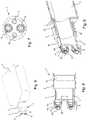
- FIG. 1 shows a perspective view of a preferred first embodiment of a lid 1 according to the invention, which has a substantially cylindrical lid housing 3 as the lateral surface, a connection piece 5 remote from the container, on the outer surface of which there is a compensation opening 7, and a valve arrangement 9 arranged at the other end of the connection piece 5.
- the valve assembly 9 includes a magnetic ball valve, which is explained in more detail with reference to the following figures.
- the compensating opening 7 is at least partially covered with a cover 11 which has a plurality of openings 13 and protects a membrane which may be underneath.
- the compensating opening 7 is arranged essentially on the peripheral or lateral surface of the connection piece 5 .
- the diameter of the cover housing 3 is dimensioned such that the connecting piece 5 and the valve arrangement 9 do not protrude beyond the outer surface in the radial direction.
- FIG. 12 shows a cross-sectional view of the embodiment of the lid 1 according to the invention 1 .
- the interior of the lid housing 3 is not shown threaded to mate with a corresponding threaded port stud or neck of a cell culture vessel.
- cover-container connections can also be used, such as bayonet lock connections, press-fit connections, plug-in connections or the like.
- the equalization opening 7 is equipped with a hydrophobic membrane 15, which enables an exchange of CO 2 (or other gases) between the interior of the cell culture container and the outside environment, in particular during storage of the cell culture container.
- the valve arrangement 9 comprises a socket or extension 19 at the end close to the container, which is connected to the connecting piece 5, and a valve housing 17 arranged at the end of the socket 19 remote from the container.
- a magnetic element 21 is arranged inside the valve housing 17 and at the end of the valve housing remote from the container
- a valve seat 25 is arranged at 17, which has a conical shape that tapers inwards, so that a magnetic ball 23 is arranged on the valve seat 25 from the outside.
- the valve seat 25 is formed from a thermoplastic plastics material. Examples of such a material are the thermoplastic elastomers (TPE) available under the trade name Mediprene 500300M from Elasto or under the trade name Thermolast M TM4RST from Kraiburg TPE. It goes without saying that the person skilled in the art can optionally also use similar plastic materials or composite materials with similar physical properties.
- the magnetic element 21 is designed as a permanent magnet, with ferromagnetic materials also being suitable.
- the ball 23 is also made of magnetic material, i.e. as a permanent magnet or as a ferromagnet, and it has a magnetic orientation which is opposite to the magnetic polarity of the magnetic element 21, in such a way that in the normal state, i.e. in the state in which the cover 1 is screwed or placed onto a cell culture container, the ball 23 and the magnetic element 21 attract each other and block the valve opening in the valve seat 25 sufficiently so that no fluid can get out of or into the cell culture container.
- all elements of the valve assembly 9, with the exception of the magnetically designed components, the magnetic element 21 and the ball 23, can be formed integrally with the other sections of the cover, e.g. embodied by a single injection molded component into which the magnetic element 21 are arranged from the inside and the ball 23 from the outside.
- a type of bellows element is arranged between the connecting piece 5 and the cover housing 3, which offers a certain degree of flexibility for the elements arranged on the connecting piece 5 in relation to the cover housing 3, but fluid-tightness between the connecting piece 5 and cover housing 3 is ensured at all times.
- the bellows element is not affected by the fact that the cover housing 3 is one piece with the connection piece 5 .
- FIG 3 shows a cross-sectional view of with reference to FIG Figures 1 and 2 described preferred embodiment of the lid according to the invention.
- a description of the elements is omitted at this point and the detailed description is referred to 2 referred.
- FIG. 4 shows a perspective representation of a further embodiment of the cover according to the invention.
- the compensating opening 7 is essentially integrated into the lateral surface of the cylindrical connecting piece 5 in that the openings 13 extend slit-like in the circumferential direction parallel to one another over a predetermined angular range of the circumference of the connecting piece 5 .
- the membrane 15 is arranged, for example, on the inner surface of the connection piece 5 in such a way that it covers the openings 13 from the inside.
- a cover 11 as in the first embodiment is the one in this embodiment 4 unavailable. All other elements of this second embodiment are the same as those with reference to FIG Figures 1 to 3 described elements of the first embodiment are identical.
- figure 5 shows a perspective representation of a lid according to the invention according to the first embodiment, which is screwed onto a cell culture container and docked at a fluid connection interface of a cell culture system.
- the cover 1 is fastened in a known manner inside its cover housing 3 by means of a thread on a corresponding threaded connector of an opening of the cell culture container.
- the valve assembly is 9 (in figure 5 not visible) docked to a corresponding connection formation of a fluid supply interface 6 of a cell culture system.
- the fluid supply interface 6 has four connection formations 8 to which corresponding supply containers for storing fluids or for receiving fluids in the operating state of the cell culture system are connected.
- connection formations 8 to which corresponding supply containers for storing fluids or for receiving fluids in the operating state of the cell culture system are connected.
- the control unit and the corresponding signaling means to control the valve arrangement 9 without contact, i.e. in particular to move the magnetic ball away from the valve seat of the valve arrangement 9 in such a way that a fluid flow path is made possible depending on the wiring or control of the fluid supply interface 6.
- the docking principle and the control within the fluid supply interface is described below with reference to the Figures 10 and 11 described in more detail.
- FIG. 6 shows a perspective view of a cell culture container with a lid according to a further embodiment of the present invention, in which a commercially available cell culture container 4 is equipped with a lid 1 according to the invention, which has not just one but two valve assemblies 9 as a significant difference from the previously described embodiments .
- the two valve arrangements 9 are arranged parallel to one another in the axial direction on the essentially cylindrical connection piece 5 , namely on the side of the lid 1 remote from the container.
- the valve arrangements 9 are of essentially identical design and are arranged essentially symmetrically with respect to the center point of the end face of the connection piece 5, which is circular in this case.
- FIG 7 is a front view of the lid 1 according to FIG 6 illustrated second embodiment. It can be seen that the end face of the connecting piece 5 has, in addition to the two valve arrangements 9, two indentations 10 which are suitable for automatically screwing on or unscrewing the cover 1 and/or for centering and thus aligning the cover 1 with respect to the cell culture container 4.
- the depressions are 10 also suitable for aligning the cover 1 with respect to the fluid supply interface 6. It should be noted at this point that the indentations 10 are not holes in the end face of the connection piece 5, but merely recesses with a sufficient depth to ensure the function described above.
- indentations 10 do not have to be arranged in the end face; there can also be more or only one depression 10 .
- shape of the recess 10 does not necessarily have to be circular. It can be rectangular, square, star-shaped, polygonal or of any other shape.
- FIG. 8 shows a cross-sectional view of a lid according to the in the Figures 6 and 7 illustrated further embodiment of the present invention.
- the cover 1 has two valve arrangements 9 in the axial direction, which are aligned parallel to one another and are of essentially identical design. Its elements are identical to those described in relation to the first preferred embodiment. For this reason, it will not be repeated here.
- valve arrangements 9 instead of one fluid flow path, two possible fluid flow paths can form when the cover 1 is docked, depending on whether the corresponding valve arrangements 9 are open or not. It is understood that the control of the two valve assemblies 9 from the 8 illustrated embodiment can be done independently. In particular, it is also possible that when one of the valve arrangements 9 is open and a fluid flows through, the other valve arrangement can be used as a pressure compensation opening in order to control the volume flow or its filling/emptying rate.
- the compensating opening 7 is provided by the membrane 15 which is arranged on the peripheral surface of the connecting piece 5 .
- the lid housing 3 is provided with a threaded section 12 in its interior which matches a corresponding threaded section on the threaded socket of the cell culture container.
- the radial expansion of the connection piece 5 provided with the two valve arrangements 9 does not protrude beyond the cover housing 3 .
- FIG. 9 shows a detail of a perspective cross-sectional view of the in 6 shown cover with connected cell culture container.
- the cover housing 3 of the cover 1 has a threaded section 12 on its inside, which fits together with a corresponding threaded section on the threaded socket 14 of the cell culture container 4 .
- the completely screwed-on state of the cover 1 is shown, whereby it can be seen that the open end of the threaded connector 14 of the cell culture container 4 abuts the stepped stop between the housing cover 3 and the connection piece 5 .
- the cover 1 is thus firmly screwed onto the cell culture container 4, with the stop described above providing additional stabilization of the connection.
- the lid according to the invention can also be used on cell culture containers which have more than one opening for attaching a lid.
- the main advantage of the present invention lies in equipping existing cell culture containers with a corresponding interface so that the existing cell culture containers can be connected to an automated cell culture system.
- the cover according to the invention in particular the valve arrangement, can include a device that prevents elements of the valve arrangement, such as the magnetic ball in the case of a magnetic ball valve, from getting lost, especially in the non-docked state.
- This can be a type of attachable or detachable (lattice) cage, preferably made of plastic, which is placed on the cover around the valve arrangement(s). It is conceivable that this cage automatically pivots to the side when the cover is docked onto the fluid supply interface or can also be removed by hand.
- valve arrangement 9 is shown on the right side of the inventive cover 1 according to the first embodiment shown here; the fluid supply interface 6 into which the valve arrangement 9 of the cover 1 is inserted can be seen on the left-hand side.
- the valve arrangement 9 is pushed into the empty space 18 , specifically in the center in such a way that the magnetic ball 23 of the valve arrangement 9 can still move essentially freely on the valve seat 25 .
- the valve arrangement 9 engages with the fluid supply interface 6 via the end ring surface of the valve seat 25 with a counter-sealing surface 20 of the fluid supply interface 6 . This fluid-tight contact of the end ring surface with the counter-sealing surface 20 ensures that no fluid can get outside the fluid flow path.
- the valve arrangement 9 is open, i.e.
- the control arrangement 24 comprises a switching arrangement 32 and a roller 28.
- the rotatable roller 28 has a (in 11 not shown) electromotive drive for rotation about the roll axis and a plurality of magnetic elements 30, which are designed as permanent magnets in the illustrated embodiment.
- the magnetic elements 30 are preferably oriented such that their NS polarization direction coincides with a radial direction extending from the roll axis. At the axial positions of the in 11 magnetic elements 30 shown, further magnetic elements 30 can be arranged along the circumference of the roller 28 .
- a switching arrangement 32 is provided between the fluid supply interface 6 and the roller 28 in order to enable precise switching of the valve arrangements docked at the fluid supply interface 6 .
- exactly one magnetic element 26 is provided on the switching arrangement 32, which is designed here as a permanent magnet.
- Each magnetic element 26 is arranged in a channel, the magnetic element 26 between a roll-near and is displaceably mounted in a position remote from the roller or closer to the valve arrangement.
- the magnetic elements 26 are selected in such a way that the magnetic field emanating from them and acting on the balls 23 of the corresponding valve arrangement 9 is stronger, at least in the position away from the roller, than the magnetic field emanating from the magnetic elements 21 on the valve seat 25 and acting on the ball 23. Furthermore, the magnetic elements 26 are preferably arranged polarized along their displacement axis, for example in such a way that a pole such as the north pole points to the associated valve arrangement and the respective opposite pole, i.e. the south pole, points to the roller 28 .
- the switching arrangement 32 is preferably arranged in such a way that the magnetic elements 26 in the channels are prestressed by gravity into their position closer to the rollers, in which, for example, the two 11 magnetic elements arranged on the right.
- the magnetic elements 26 can be shifted from their position closer to the roller to their position further away from the roller or closer to the valve arrangement by the magnetic fields emanating from the magnetic elements 30, for example by lying opposite one another of poles of the same orientation, i.e. of poles that repel each other.
- the magnetic elements 30 and the magnetic elements 26 will attract each other and thus exert an attractive force in addition to the force of gravity.
- electromagnets can also be used as actuators in order to cause the valves to open and close.
- piezoelectric valves can also be used or other valves known to the person skilled in the art, which are easy to clean, especially on the side remote from the container, in order to avoid contamination in the automated cell culture system as far as possible .
- a cover for a cell culture container which can be used with standard cell culture containers used to date, is inexpensive to produce and has a simple structure.
Landscapes
- Health & Medical Sciences (AREA)
- Chemical & Material Sciences (AREA)
- Life Sciences & Earth Sciences (AREA)
- Organic Chemistry (AREA)
- Wood Science & Technology (AREA)
- Engineering & Computer Science (AREA)
- Bioinformatics & Cheminformatics (AREA)
- Zoology (AREA)
- General Engineering & Computer Science (AREA)
- Sustainable Development (AREA)
- Microbiology (AREA)
- Biochemistry (AREA)
- Biomedical Technology (AREA)
- General Health & Medical Sciences (AREA)
- Genetics & Genomics (AREA)
- Biotechnology (AREA)
- Clinical Laboratory Science (AREA)
- Analytical Chemistry (AREA)
- Molecular Biology (AREA)
- Apparatus Associated With Microorganisms And Enzymes (AREA)
Description
- Die vorliegende Erfindung betrifft einen Deckel für Zellkulturbehälter, wie sie üblicherweise zur industriemäßigen Kultivierung von adhärenten Zellen in Laboren der Pharma- bzw. Biotechnologieindustrie eingesetzt werden.
- Auf dem Gebiet der Zellkultur bekannt sind Zellkulturbehälter, die in der Regel aus durchsichtigem Kunststoff, häufig als Wegwerf- oder Einwegbehälter, ausgebildet sind und über einen oder mehrere Schraubverschlüsse verfügen. Die Zellkulturbehälter werden dazu verwendet, um Zellen zu vermehren bzw. zu kultivieren und dabei das Wachstum zu beobachten. Dazu werden die zu kultivierenden Zellen zusammen mit einem geeigneten Nährmedium in den Behälter (oft in Flaschenform) hineingegeben, wo sie sich bei entsprechenden Umgebungsbedingungen vermehren können. Das Innere des Zellkulturbehälters umfasst ein Volumen, das deshalb als Kulturvolumen bezeichnet wird. Die Umgebungsbedingungen sind in der Regel eine Umgebungstemperatur von 37°C mit einem CO2-Gehalt von 5 % sowie einer relativen Luftfeuchtigkeit (rH) von 95 %. Sobald ein gewisser Abdeckungsgrad der Oberfläche des Zellkulturbehälters mit den adhärenten Zellen erreicht ist (Konfluenzgrad), müssen die Zellen entweder für die weitere Verwendung geerntet oder auf mehrere neue Zellkulturbehälter aufgeteilt werden. In manchen Fällen ist es auch notwendig, während der Kultivierung das Nährmedium auszutauschen (cell maintenance). Für den Austausch von Nährmedium und/oder die Entnahme von adhärenten Zellen, gegebenenfalls mit oder ohne Nährmedium, wird hierin zusammenfassend der Begriff Fluid verwendet.
- Bei kleinen Mengen von zu kultivierenden Zellen, d. h. im einfachsten Fall, werden die oben genannten Prozessschritte in der Zellkultur manuell unter Zuhilfenahme von Handpipetten unter einem Sterilabzug durch entsprechend ausgebildete technische Assistenten durchgeführt. D. h. die Deckel der Zellkulturbehälter werden per Hand abgeschraubt und nach Befüllung bzw. Entnahme auch wieder manuell verschlossen. Eigens dafür vorgesehene Schüttelmaschinen und andere Laborgeräte ersetzen bereits Teilprozessvorgänge, um nicht sämtliche Tätigkeiten manuell durchführen zu müssen.
- Für größere Mengen von Zellkulturen sind im Markt vollautomatisierte Lösungen bekannt, die sämtliche auszuführenden Schritte mit mechanischen Robotern durchführen, wie z. B. 6-Achs-Roboter der Firmen TAP oder Kawasaki. Bei diesen Roboterlösungen können die-
10180 P 4981 WO
selben Zellkulturbehälter wie bei der manuellen Bearbeitung verwendet werden, was die Kosten für eine Neuanschaffung von Zellkulturbehältern vermeidet. Nachteilig an den automatisierten Roboterlösungen ist jedoch, dass der Durchsatz und die Geschwindigkeit der Verarbeitung sehr begrenzt und eine sinnvolle Parallelisierung bzw. Verschachtelung der Prozessschritte kaum möglich ist. - Die derzeit im Einsatz befindlichen Zellkulturbehälter verfügen über Schraubdeckel bzw. -verschlüsse, die wahlweise mit oder ohne Belüftungsmembran ausgeführt sind, um einen gezielten CO2-Austausch mit den Zellen im Inneren der Flasche zu gewährleisten. Ein wichtiger Aspekt bei diesen Belüftungs- oder Filtermembranen ist, dass die Porengröße der Membran 0,22 µm nicht überschreitet, damit die Membran noch als Sterilmembran angesehen werden kann.
- Des Weiteren existieren noch Sonderbauformen von Zellkulturbehältern mit Durchstechmembranen, die beispielsweise als hydrophobe Filtermembranen ausgebildet sind, wie z. B. die von der Firma Greiner Bio-One angebotene Zellkulturflasche "AutoFlask". Derartige Zellkulturbehälter sind für Automatisierungsprozesse optimiert, mit einer Vielfalt von Zellkultur- und Liquid Handling Systemen kompatibel und weisen beispielsweise ein physikalische Oberflächenbehandlung für adhärente Zellen auf. Nachteilig an derartigen Produkten ist jedoch, dass der Benutzer genau auf die Bauform, die Größe und die Oberflächeneigenschaften eingeschränkt ist. Aus diesem Grund finden derartige Systeme bisher nur begrenzt Einsatz.
- Die deutsche Patentanmeldung
DE 10 2013 201 069 der Anmelderin ist auf eine Zellkulturanlage mit einer Fluid-Versorgungsschnittstelle und einem speziell dafür konzipierten Zellkulturbehälter gerichtet, wobei der Zellkulturbehälter eine Einfüll- oder/und Belüftungsöffnung, sowie mindestens eine von der Einfüll- oder/und Belüftungsöffnung gesondert ausgebildete Gegenkopplungsformation aufweist, welche zur Herstellung und zur Lösung eines Kopplungseingriffs mit einer entsprechenden Kopplungsformation der Fluid-Versorgungsschnittstelle ausgebildet ist. Diese Zellkulturanlage bzw. dieser Zellkulturbehälter ist ebenfalls speziell an die entsprechende Anlage bzw. Schnittstelle angepasst, weshalb die bisher verwendeten Standard-Zellkulturbehälter nur zum Teil oder sehr eingeschränkt verwendet werden können. Um ein ganzes Labor bzw. eine Fertigung mit derartigen neuartigen Zellkulturbehältern auszustatten, sind deshalb sehr hohe Investitionen erforderlich. - Die
US 2011/223076 A1 offenbart ein Anschlussstück für ein Bioreaktorgefäß. Das Anschlussstück weist eine Mehrzahl von Anschlüssen auf, die zum einen zur Einführung von Fühlern oder Sonden und zum anderen zur Zuführung einer Probe geeignet sind, sowie eine Ventilanordnung für einen Reinigungsanschluss. - Die
DE 42 07 346 A1 offenbart eine Steuervorrichtung für ein Ventil eines Rotationsfüllers für die Getränkeindustrie, die ein Ventil mit einem in einem Ventilgehäuse zwischen einer Öffnungs- und einer Schließstellung bewegbar gelagerten Ventilstößel und einen in diesem angeordneten Stößelmagneten aufweist. Weiterhin ist wenigstens ein außerhalb des Ventilgehäuses angeordneter Steuermagnet vorhanden, welcher bei Drehung des Rotationsfüllers eine mit dem Stößelmagneten wechselwirkende Kontaktstellung durchläuft. Zur Vereinfachung der Steuervorrichtung und zur Sicherung von Öffnungs- bzw. Schließstellung besteht wenigstens ein Teil des Ventilgehäuses aus einem magnetisierbaren Material, an welchem der Stößelmagnet nach Durchlaufen der Kontaktstelle haftet, und ein zum Steuermagneten nachgeordneter und umgekehrt magnetisch gepolter Trennmagnet ist angeordnet, der den Stößelmagnet löst, wodurch der Ventilstößel bistabil anordenbar ist.US5848622 offenbart einen Verschluss für ein Bioreaktorgefäß, bestehend aus einem Deckel (20) mit einem Verteilelement (24) sowie einem Ventilelement (28). Das Ventilelement (24) hat die Funktion, dass beim manuellen Öffnen des Deckels das Bioreaktorgefäß entlüftet wird. - Es ist daher die Aufgabe der vorliegenden Erfindung, eine technische Lehre für einen Deckel eines Zellkulturbehälters anzugeben, wobei der Deckel die nicht nur die oben beschriebenen Nachteile überwindet, sondern auch mit bisher verwendeten Standard-Zellkulturbehältern verwendet werden kann, günstig herzustellen ist, und einen einfachen Aufbau aufweist.
- Diese Aufgabe wird durch den Gegenstand des Anspruchs 1 gelöst. Vorteilhafte Ausführungsformen sind in den abhängigen Ansprüchen beschrieben.
- Erfindungsgemäß wird ein Deckel für einen Zellkulturbehälter bereitgestellt, der ein Kulturvolumen umschließt und eine Öffnung aufweist, mit einer Ventilanordnung, geeignet zum Befüllen des Zellkulturbehälters mit einem Fluid und/oder zum Abpumpen von Fluid aus dem Zellkulturbehälter, und einer Ausgleichsöffnung, die zur Belüftung des Zellkulturbehälters und/oder zum Druckausgleich während des Befüllens oder Abpumpens geeignet ist, wobei die Ventilanordnung zwischen einer Durchlassstellung und einer Sperrstellung magnetisch schaltbar und an eine Fluid-Versorgungsschnittstelle anschließbar und als berührungslos schaltbar mit magnetischen Elementen ausgebildet ist. Durch die Integration der Ventilanordnung in den Deckel bzw.
- Verschluss können bereits vorhandene Zellkulturbehälter problemlos in einer automatisierten Zellkulturanlage verwendet werden. Die Umrüstung von einer manuellen Verarbeitung zu einer im Wesentlichen automatisierten Zellkulturanlage erfordert damit lediglich die Investitionen in neue Deckel für bereits vorhandene Zellkulturbehälter. Durch die in den Deckel bzw. Verschluss integrierte Ausgleichsöffnung entfällt die Anforderung nach einer weiteren Öffnung im Zellkulturbehälter. Ein ordnungsgemäßer CO2 Austausch ist damit gewährleistet. Ebenso ist dadurch ein ausreichender Volumenstrom beim Befüllen bzw. Entleeren des Zellkulturbehälters gesichert. Zudem ist der Aufbau des Deckels einfach und seine Herstellung kostengünstig, insbesondere im Vergleich zur speziellen Herstellung eines gesamten Zellkulturbehälters für eine automatisierte Zellkulturanlage.
- Durch die als berührungslos schaltbar ausgebildete Ventilanordnung lassen sich automatisierte Zellkultursysteme bzw. -anlagen mit einem mit dem erfindungsgemäßen Deckel ausgestatteten Zellkulturbehälter auf einfache Weise nutzen. Die berührungslose Schaltbarkeit erlaubt einen einfachen Aufbau sowie eine besonders einfache Handhabung, da keine Kabel oder sonstige Verbindungen mit dem Deckel verbunden werden müssen, um die Öffnung bzw. das Schließen der Ventilanordnung zu bewirken. Dies ermöglicht es insbesondere, eine automatisierte Zellkulturanlage auf einfache Weise zu reinigen, im Gegensatz zu Schaltmechanismen von Ventilanordnungen, die nur durch Berührung zu öffnen bzw. zu schließen sind und durch den komplexen Aufbau nur mit hohem Aufwand zu reinigen sind. Mit besonderem Vorteil ist die Ausgleichsöffnung wahlweise als sich öffnen lassend und/oder als Membran ausgebildet. Damit kann die Ausgleichsöffnung während des Befüll- oder Entleerungsvorgangs geöffnet oder geschlossen werden, je nachdem, ob der Volumenstrom erhöht oder herabgesetzt werden soll. Die Ausbildung als Membran, vorzugsweise hydrophobe Membran, ist für den CO2 Austausch im Ruhezustand wichtig, d.h. dann, wenn keine Entnahme, Befüllung bzw. kein Abpumpen stattfindet. Auch kann die Ausgleichsöffnung wie z.B. eine derartige Membran beispielsweise durch ein Gitter vor Beschädigungen geschützt sein ohne Beeinträchtigungen in ihrer Funktion hinnehmen zu müssen. Sofern der Deckel im Wesentlichen eine zylindrische Form aufweist, kann die Ausgleichsöffnung auf der Mantelfläche oder auch auf der Stirnfläche des Deckels angeordnet sein.
- Besonders bevorzugt sind die Ventilanordnung und die Öffnung des Zellkulturbehälters koaxial angeordnet. D.h. dass die Ventilanordnung bei einer Zylinderform des Deckels im Wesentlichen in der Mitte der Stirnfläche des Deckels angeordnet ist, also in Verlängerung der gemeinsamen Achse. Bei dieser Anordnung ist die Ausgleichsöffnung vorteilhafter Weise auf der Mantelfläche angeordnet.
- Mit weiterem Vorteil ist die Ausgleichsöffnung derart gestaltet, dass sie bei nicht an die Fluid-Versorgungsschnittstelle angeschlossener Ventilanordnung geschlossen ist und bei an die Fluid-Versorgungsschnittstelle angeschlossener Ventilanordnung geöffnet ist. Dies entspricht einer Andockfunktion, nach der die Ausgleichsöffnung erst dann geöffnet ist, wenn die Ventilanordnung des Deckels in dem Gegenstück, d.h. dem Port der Fluid-Versorgungsschnittstelle angeordnet ist. Beispielsweise erfolgt dies mittels eines mechanischen Schiebemechanismus, der eine Rückstellfeder aufweist.
- Vorteilhafterweise ist der Deckel mit der Öffnung des Zellkulturbehälters mittels einer Gewindeverbindung, einer Bajonettverschlussverbindung, einer Presssitzverbindung, einer Schnapp- oder Steckverbindung oder einer Kombination daraus lösbar verbindbar. Die Verbindung mittels Gewinde, also der klassische Schraubverschluss, wird die hauptsächlich eingesetzte Verbindungsmöglichkeit sein, weil die bisher verwendeten Zellkulturbehälter über eine Öffnung mit einem Schraubgewinde verfügen. Es wird an dieser Stelle bemerkt, dass die entsprechende Verbindung auch mit Dichtungen versehen sein kann.
- Mit besonderem Vorteil umfasst die Ventilanordnung ein magnetisches Kugelventil, wobei auf der behälternahen Seite der Ventilanordnung am Ventilsitz ein Magnetelement und auf der behälterfernen Seite der Ventilanordnung eine Kugel aus magnetischem Material angeordnet ist. Das magnetische Kugelventil hat den Vorteil, dass es kaum Fläche verbraucht, einfach aufgebaut ist und die behälterferne Seite des Deckels mit der Kugel relativ einfach gereinigt werden kann und damit eine wesentliche Anforderung an ein automatisches Zellkultursystem erfüllt ist, nämlich Kontaminationen der Zellkulturen so weit wie möglich zu reduzieren. Wie weiter unten ausführlicher beschrieben erfolgt die Steuerung des Kugelventils durch die Steuerungseinheit innerhalb der Fluid-Versorgungsschnittstelle. In geschlossenem Zustand wirken die magnetischen Kräfte der Kugel und das Magnetelement am Ventilsitz derart, dass sich die entsprechenden Elemente anziehen und somit die Kugel relativ fest auf dem Ventilsitz aufsitzt und damit Fluid daran gehindert ist, in den Zellkulturbehälter hinein oder aus ihm heraus zu strömen. Die von der Steuerungseinheit der Fluid-Versorgungsschnittstelle angesteuerten magnetischen Elemente sind im angedockten Zustand derart in der Nähe der Kugel angeordnet und so dimensioniert, dass eine Aktivierung der magnetischen Elemente ein magnetisches Feld erzeugt, das die Kugel aus ihrer geschlossenen Position heraus bewegt und damit der Strömungsweg für das Fluid freigegeben ist.
- Bevorzugterweise ist der Ventilsitz konisch oder halbkugelförmig ausgebildet. Damit wird im geschlossenen Zustand die Kugel wirksam auf dem Ventilsitz gehalten und kann nur mit einer entsprechenden Minimalkraft von dort wegbewegt werden. Grundsätzlich ist es allerdings auch möglich, dass der Ventilsitz flach ausgebildet ist. Eine Reinigung ist dann besonders effektiv möglich, da die Zwischenräume für die Reinigungsflüssigkeit besser zugänglich sind.
- Vorteilhafte Weise umfasst der Ventilsitz ein thermoplastisches Kunststoffmaterial wie TPE, Silikon oder dergleichen, wobei das thermoplastische Kunststoffmaterial bevorzugt eine Shore A Härte von etwa 25 bis etwa 50 aufweist. Derartige Materialien verleihen dem Ventilsitz eine im Wesentlichen leicht verformbare Eigenschaft und führen damit zu einer verbesserten Dichtwirkung der Ventilanordnung. Möglich ist es dabei auch, dass der Ventilsitz aus unterschiedlichen Materialien durch Zwei-Komponenten-Spritzguss hergestellt wird.
- Bevorzugt ist der Deckel mit Ausnahme der Ventilanordnung einstückig aus Kunststoff mittels Spritzguss hergestellt, und die Ventilanordnung ist im Presssitz darauf aufsteckbar. Spritzguss ist bei den einschlägigen Kunststoffen wie PP, PE, PVC und dergleichen eine bewährte, technisch ausgereifte und sehr preisgünstige Herstellungsvariante. Durch das einfache Aufstecken der Ventilanordnung ist eine einfache Konstruktion gegeben. Optional können einzelne Bestandteile der Ventilanordnung (bei Ausbildung als magnetisches Kugelventil alle bis auf die magnetische Kugel und das Magnetelement) ebenfalls aus Kunststoff im Spritzgussverfahren hergestellt sein, auch durch Spritzguss mit zwei oder mehr Komponenten. Diese lassen sich mit den anderen Bestandteilen und den Deckelelementen auf einfache Art und Weise zu dem erfindungsgemäßen Deckel montieren. Damit ist es auch möglich, den Deckel als Einmal- /Wegwerfartikel auszugestalten, um den Aufwand für die Wiederaufbereitung nach Verwendung zu vermeiden.
- Mit weiterem Vorteil weist der Deckel als Ausgleichsöffnung eine weitere Ventilanordnung auf. Anstatt einer eigenen "einfachen" Ausgleichsöffnung kann eine weitere Ventilanordnung deren Funktion übernehmen. Zur Trennung der Ventilanordnungen kann beispielsweise ein Siphon verwendet werden.
- Es ist erfindungsgemäß auch möglich, mehrere Ventilanordnungen in dem Deckel, vorzugsweise nebeneinander, anzuordnen. Damit kann den Anforderungen an die Reinheit bzw. die Vermeidung von Kontamination noch stärker Rechnung getragen werden, z.B. in dem man eine Ventilanordnung nur für das Einleiten und eine weitere Ventilanordnung nur für das Abpumpen bzw. Herausleiten verwendet.
- Die Erfindung wird nachfolgend ausführlich unter Bezugnahme auf in den Zeichnungen dargestellte Ausführungsbeispiele erläutert. Es zeigen:
- Fig. 1
- eine perspektivische Darstellung einer bevorzugten Ausführungsform des erfindungsgemäßen Deckels für einen Zellkulturbehälter;
- Fig. 2
- eine perspektivische Querschnittsansicht des erfindungsgemäßen Deckels aus
Fig. 1 ; - Fig. 3
- eine Querschnittsansicht des erfindungsgemäßen Deckels aus
Fig. 1 ; - Fig. 4
- eine perspektivische Ansicht einer zweiten Ausführungsform des erfindungsgemäßen Deckels;
- Fig. 5
- einen erfindungsgemäßen Deckeln gemäß der ersten Ausführungsform, aufgesetzt auf einen Zellkulturbehälter sowie angedockt an eine Fluid-Verbindungsschnittstelle eines Zellkultursystems;
- Fig. 6
- eine perspektivische Ansicht eines Zellkulturbehälters mit einem Deckel gemäß einer weiteren Ausführungsform der vorliegenden Erfindung;
- Fig. 7
- eine Vorderansicht des Deckels aus
Fig. 6 ; - Fig. 8
- eine Querschnittansicht eines Deckel gemäß der in den
Fig. 6 und 7 dargestellten weiteren Ausführungsform der vorliegenden Erfindung; - Fig. 9
- ein Detail einer perspektivischen Querschnittansicht des in
Fig. 6 dargestellten Deckels mit Zellkulturbehälter; - Fig. 10
- eine Querschnittsansicht eines Details der Darstellung aus
Fig. 5 ; und - Fig. 11
- eine schematische Darstellung, die beispielhaft die Interaktion zwischen dem erfindungsgemäßen Deckel und einem Zellkultursystem gemäß einer bevorzugten Ausführungsform der Erfindung.
-
Fig. 1 zeigt in perspektivischer Darstellung eine bevorzugte erste Ausführungsform eines erfindungsgemäßen Deckels 1, der ein im Wesentlichen zylinderförmiges Deckelgehäuse 3 als Mantelfläche, ein behälterfernes Anschlussstück 5, an dessen Außenfläche sich eine Ausgleichsöffnung 7 befindet, sowie eine am anderen Ende des Anschlussstücks 5 angeordnete Ventilanordnung 9 aufweist. Die Ventilanordnung 9 umfasst ein magnetisches Kugelventil, das unter Bezugnahme auf die nachfolgenden Figuren näher erläutert wird. Die Ausgleichsöffnung 7 ist in dieser Ausführungsform zumindest teilweise mit einer Abdeckung 11 bedeckt, die mehrere Öffnungen 13 aufweist und eine gegebenenfalls darunter liegende Membran schützt. Die Ausgleichsöffnung 7 ist im Wesentlichen auf der Umfangs- bzw. Mantelfläche des Anschlussstücks 5 angeordnet. Der Durchmesser des Deckelgehäuses 3 ist so bemessen, dass das Anschlussstück 5 und die Ventilanordnung 9 in radialer Richtung nicht über die Mantelfläche hinausragen. Dies hat den Vorteil, dass bei einer Lagerung der erfindungsgemäßen Deckel 1 die empfindlichen Elemente wie die Ventilanordnung 9 oder die Ausgleichsöffnung 7 nicht bzw. in nur geringem Maße beschädigt werden können, wenn mehrere Deckel 1 zusammen, insbesondere nebeneinander, gelagert sind. InFig. 1 ist auch gut erkennbar, dass die Ventilanordnung 9 eine relativ kleine Oberfläche aufweist, so dass die zu reinigende Fläche bei einem Fluidwechsel möglichst gering ist. -
Fig. 2 zeigt eine Querschnittsansicht der Ausführungsform des erfindungsgemäßen Deckels 1 ausFig. 1 . In der dargestellten Ausführungsform ist das Innere des Deckelgehäuses 3 nicht mit einem Gewinde abgebildet, das auf einen entsprechenden, mit einem Gewinde versehenen Öffnungsstutzen oder -ansatz eines Zellkulturbehälters passt. Es versteht sich, dass neben den üblichen Gewindeverbindungen auch andere Arten von Deckel-Behälter-Verbindungen verwendet werden können wie z.B. Bajonettverschlussverbindungen, Presssitzverbindungen, Steckverbindungen oder dergleichen. Die Ausgleichsöffnung 7 ist neben einer (äußeren) Abdeckung 11 mit einer hydrophoben Membran 15 ausgestattet, die einen Austausch von CO2 (oder anderen Gasen) zwischen dem Inneren des Zellkulturbehälters und der äußeren Umgebung insbesondere während der Lagerung des Zellkulturbehälters ermöglicht. - Die Ventilanordnung 9 umfasst am behälternahen Ende einen Stutzen oder Ansatz 19, der mit dem Anschlussstück 5 verbunden ist, sowie ein am behälterfernen Ende des Stutzens 19 angeordnetes Ventilgehäuse 17. In dem Ventilgehäuse 17 ist innen ein Magnetelement 21 angeordnet, und am behälterfernen Ende des Ventilgehäuses 17 ist ein Ventilsitz 25 angeordnet, der eine konisch nach innen zulaufende Form aufweist, so dass von außen eine magnetische Kugel 23 auf dem Ventilsitz 25 angeordnet ist. In der dargestellten Ausführungsform ist der Ventilsitz 25 aus einem thermoplastischen Kunststoffmaterial ausgebildet. Beispiele für ein derartiges Material sind die thermoplastischen Elastomere (TPE), die unter dem Handelsnamen Mediprene 500300M von der Firma Elasto oder unter dem Handelsnamen Thermolast M TM4RST von der Firma Kraiburg TPE erhältlich sind. Es versteht sich, dass der Fachmann optional auch ähnliche Kunststoffmaterialien oder Verbundwerkstoffe mit ähnlichen physikalischen Eigenschaften verwenden kann.
- Das Magnetelement 21 ist in der dargestellten Ausführungsform als Permanentmagnet ausgebildet, wobei auch ferromagnetische Materialien geeignet sind. Die Kugel 23 ist ebenfalls aus magnetischem Material ausgebildet, also als Permanentmagnet oder als Ferromagnet, und sie weist eine magnetische Ausrichtung auf, die entgegengesetzt der magnetischen Polung des Magnetelements 21 ist, und zwar derart, dass im normalen Zustand, d.h. in dem Zustand, in dem der Deckel 1 auf einen Zellkulturbehälter aufgeschraubt bzw. aufgesetzt ist, die Kugel 23 und das Magnetelement 21 sich anziehen und die Ventilöffnung im Ventilsitz 25 ausreichend versperren, so dass kein Fluid aus dem Zellkulturbehälter heraus bzw. dort hinein gelangen kann.
- Es ist anzumerken, dass als besondere Ausführungsform alle Elemente der Ventilanordnung 9 mit Ausnahme der magnetisch ausgebildeten Bauteile, dem Magnetelement 21 sowie der Kugel 23, integral mit den anderen Abschnitten des Deckels ausgebildet sein können, beispielsweise verkörpert durch ein einziges Spritzgussbauteil, in das das Magnetelement 21 von innen sowie die Kugel 23 von außen angeordnet sind.
- Zwischen dem Anschlussstück 5 und dem Deckelgehäuse 3 ist eine Art Balgenelement angeordnet, das für einen gewissen Grad an Flexibilität der an dem Anschlussstück 5 angeordneten Elemente bezogen auf das Deckelgehäuse 3 bietet, wobei jedoch jederzeit eine Fluiddichtigkeit zwischen Anschlussstück 5 und Deckelgehäuse 3 gewährleistet ist. Das Balgenelement wird durch die Einstückigkeit des Deckelgehäuses 3 zusammen mit dem Anschlussstück 5 nicht beeinflusst. Mit anderen Worten, es ist möglich, einen erfindungsgemäßen Deckel 1 als ein integrales Spritzgussteil umfassend das Deckelgehäuse 3, Anschlussstück 5 und dazwischen liegendem Balgenelement auszubilden.
-
Fig. 3 zeigt eine Querschnittsdarstellung der unter Bezugnahme auf dieFig. 1 und 2 beschriebenen bevorzugten Ausführungsform des erfindungsgemäßen Deckels. Um Wiederholungen zu vermeiden, wird an dieser Stelle auf eine Beschreibung der Elemente verzichtet und auf die ausführliche Beschreibung zuFig. 2 verwiesen. -
Fig. 4 zeigt eine perspektivische Darstellung einer weiteren Ausführungsform des erfindungsgemäßen Deckels. Der Unterschied zu der in denFig. 1 bis 3 dargestellten Ausführungsform liegt darin, dass die Ausgleichsöffnung 7 im Wesentlichen in die Mantelfläche des zylinderförmigen Anschlussstücks 5 integriert ist, indem die Öffnungen 13 sich schlitzartig in Umfangsrichtung parallel zueinander über einen vorbestimmten Winkelbereich des Umfangs des Anschlussstücks 5 erstrecken. Die Membran 15 ist dabei beispielsweise auf der Innenfläche des Anschlussstücks 5 derart angeordnet, so dass sie die Öffnungen 13 von innen abdeckt. Eine Abdeckung 11 wie in der ersten Ausführungsform ist in dieser Ausführungsform derFig. 4 nicht vorhanden. Alle weiteren Elemente dieser zweiten Ausführungsform sind mit denen der unter Bezugnahme auf dieFig. 1 bis 3 beschriebenen Elemente der ersten Ausführungsform identisch. -
Fig. 5 zeigt eine perspektivische Darstellung eines erfindungsgemäßen Deckels gemäß der ersten Ausführungsform, der auf einen Zellkulturbehälter aufgeschraubt und an eine Fluid-Verbindungsschnittstelle eines Zellkultursystems angedockt ist. Der Deckel 1 ist im Inneren seines Deckelgehäuses 3 mittels eines Gewindes an einem entsprechenden Gewindestutzen einer Öffnung des Zellkulturbehälters in bekannter Weise befestigt. Auf der behälterfernen Seite ist die Ventilanordnung 9 (inFig. 5 nicht sichtbar) an einer entsprechenden Anschlussformation einer Fluid-Versorgungsschnittstelle 6 eines Zellkultursystems angedockt. - Die Fluid-Versorgungsschnittstelle 6 weist vier Anschlussformationen 8 auf, an die entsprechende Versorgungsbehälter für die Bevorratung von Fluiden bzw. zur Aufnahme von Fluiden im Betriebszustand des Zellkultursystems angeschlossen werden. In
Fig. 5 nicht sichtbar dargestellt sind die Steuereinheit sowie die entsprechenden Signalmittel, um die Ventilanordnung 9 berührungslos zu steuern, d. h. insbesondere die magnetische Kugel vom Ventilsitz der Ventilanordnung 9 derart wegzubewegen, so dass ein Fluiddurchflusspfad je nach Beschaltung bzw. Steuerung der Fluid-Versorgungsschnittstelle 6 ermöglicht wird. Das Andockprinzip sowie die Steuerung innerhalb der Fluid-Versorgungsschnittstelle wird unten unter Bezugnahme auf dieFig. 10 und 11 näher beschrieben. -
Fig. 6 zeigt eine perspektivische Ansicht eines Zellkulturbehälters mit einem Deckel gemäß einer weiteren Ausführungsform der vorliegenden Erfindung, bei der ein handelsüblich erhältlicher Zellkulturbehälter 4 mit einem erfindungsgemäßen Deckel 1 ausgestattet ist, der als wesentlicher Unterschied zu den zuvor beschriebenen Ausführungsformen nicht nur eine, sondern zwei Ventilanordnungen 9 aufweist. Die beiden Ventilanordnungen 9 sind parallel zueinander in axialer Richtung auf dem im Wesentlichen zylinderförmigen Anschlussstück 5 angeordnet, und zwar auf der behälterfernen Seite des Deckels 1. Die Ausgleichsöffnung 7 ist auf der Umfangsfläche des Anschlussstücks 5 angeordnet. Die Ventilanordnungen 9 sind im Wesentlichen identisch ausgebildet und im Wesentlichen symmetrisch bezüglich des Mittelpunkts der hier kreisförmigen Stirnfläche des Anschlussstücks 5 angeordnet. -
Fig. 7 ist eine Vorderansicht des Deckels 1 gemäß der inFig. 6 dargestellten zweiten Ausführungsform. Man erkennt, dass die Stirnfläche des Anschlussstücks 5 neben den beiden Ventilanordnungen 9 noch zwei Vertiefungen 10 aufweist, die zum automatischen Aufschrauben bzw. Abschrauben des Deckels 1 und/oder zum Zentrieren und damit Ausrichten des Deckels 1 bezüglich des Zellkulturbehälters 4 geeignet sind. Die Vertiefungen 10 sind auch dazu geeignet, um den Deckel 1 bezüglich der Fluid-Versorgungsschnittstelle 6 auszurichten. Es ist an dieser Stelle anzumerken, dass die Vertiefungen 10 keine Löcher in der Stirnfläche des Anschlussstücks 5 sind, sondern lediglich Ausnehmungen mit einer ausreichenden Tiefe, um die oben beschriebene Funktion zu gewährleisten. - Es versteht sich, dass erfindungsgemäß nicht exakt zwei Vertiefungen 10 in der Stirnfläche angeordnet sein müssen; es können auch mehr oder lediglich eine Vertiefung 10 vorhanden sein. Des Weiteren muss die Form der Vertiefung 10 nicht notwendigerweise kreisförmig sein. Sie kann rechteckig, quadratisch, sternförmig, polygonal oder andersartig ausgebildet sein.
-
Fig. 8 zeigt eine Querschnittsansicht eines Deckels gemäß der in denFig. 6 und 7 dargestellten weiteren Ausführungsform der vorliegenden Erfindung. Wie bereits oben erläutert, weist der Deckel 1 in axialer Richtung zwei Ventilanordnungen 9 auf, die parallel zueinander ausgerichtet sind und im Wesentlichen identisch ausgebildet sind. Ihre Elemente sind identisch zu denen, die in Bezug auf die erste bevorzugte Ausführungsform beschrieben wurden. Aus diesem Grund wird auf eine Wiederholung an dieser Stelle verzichtet. - Man erkennt, dass sich anstatt einem Fluidströmungspfad bei angedocktem Deckel 1 zwei mögliche Fluidströmungspfade ausbilden können, je nachdem ob die entsprechenden Ventilanordnungen 9 geöffnet sind oder nicht. Es versteht sich, dass die Steuerung der beiden Ventilanordnungen 9 aus der in
Fig. 8 dargestellten Ausführungsform unabhängig voneinander erfolgen kann. Insbesondere ist es auch möglich, dass, wenn eine der Ventilanordnungen 9 geöffnet ist und ein Fluid durchströmt, die andere Ventilanordnung als Druckausgleichsöffnung verwendet werden kann, um den Volumenstrom bzw. dessen Befüll- / Entleerrate zu steuern. Die Ausgleichsöffnung 7 ist in der hier dargestellten Ausführungsform durch die Membran 15 vorgesehen, die auf der Umfangsfläche des Anschlussstückes 5 angeordnet ist. - Im Gegensatz zu den zuvor dargestellten Ausführungsformen ist in dieser Ausführungsform des Deckels 1 das Deckelgehäuse 3 in seinem Innern mit einem Gewindeabschnitt 12 versehen, das zu einem entsprechenden Gewindeabschnitt auf dem Gewindestutzen des Zellkulturbehälters passt. Auch in dieser Ausführungsform erkennt man, dass die radiale Ausdehnung des mit den beiden Ventilanordnungen 9 versehenen Anschlussstücks 5 nicht über das Deckelgehäuse 3 hinausragt.
-
Fig. 9 zeigt ein Detail einer perspektivischen Querschnittansicht des inFig. 6 dargestellten Deckels mit angeschlossenem Zellkulturbehälter. Wie bereits unter Bezugnahme aufFig. 8 beschrieben, weist das Deckelgehäuse 3 des Deckels 1 auf seiner Innenseite einen Gewindeabschnitt 12 auf, der mit einem entsprechenden Gewindeabschnitt auf dem Gewindestutzen 14 des Zellkulturbehälters 4 zusammenpasst. InFig. 9 ist der vollständig aufgeschraubte Zustand des Deckels 1 dargestellt, wobei man erkennt, dass das offene Ende des Gewindestutzens 14 des Zellkulturbehälters 4 an den stufenförmigen Anschlag zwischen Gehäusedeckel 3 und Anschlussstück 5 anstößt. Damit ist der Deckel 1 auf den Zellkulturbehälter 4 fest aufgeschraubt, wobei der zuvor beschriebene Anschlag eine zusätzliche Stabilisierung der Verbindung bereitstellt. - Es versteht sich, dass der erfindungsgemäße Deckel auch auf Zellkulturbehältern eingesetzt werden kann, die mehr als eine Öffnung zur Anbringung eines Deckels aufweisen. Der Hauptvorteil der vorliegenden Erfindung liegt jedoch darin, bereits existierende Zellkulturbehälter mit einer entsprechenden Schnittstelle auszurüsten, damit die bereits existierenden Zellkulturbehälter an ein automatisiertes Zellkultursystem angeschlossen werden können.
- Weiterhin ist anzumerken, dass der erfindungsgemäße Deckel, insbesondere die Ventilanordnung eine Vorrichtung umfassen kann, die verhindert, dass vor allem im nicht angedockten Zustand Elemente der Ventilanordnung wie z.B. die magnetische Kugel im Falle eines magnetischen Kugelventils nicht verloren geht. Dabei kann es sich um eine Art aufsteckbaren bzw. abnehmbaren (Gitter-) Käfig, vorzugsweise aus Kunststoff, handeln, der um die Ventilanordnung(en) herum auf den Deckel aufgesetzt wird. Es ist dabei vorstellbar, dass dieser Käfig bei Andocken des Deckels an die Fluid-Versorgungsschnittstelle automatisch zur Seite schwenkt oder auch per Hand entfernt werden kann.
- Unter Bezugnahme auf die
Fig. 10 und 11 soll nun kurz die Funktionsweise der Interaktion eines erfindungsgemäßen Deckels mit einer Fluid-Versorgungsschnittstelle näher erläutert werden. - In
Fig. 10 ist auf der rechten Seite der erfindungsgemäße Deckel 1 gemäß der ersten hier dargestellten Ausführungsform abgebildet; auf der linken Seite ist die Fluid-Versorgungsschnittstelle 6 zu erkennen, in die die Ventilanordnung 9 des Deckels 1 eingeschoben wird. Dabei wird die Ventilanordnung 9 in den Leerraum 18 eingeschoben, und zwar derart mittig, dass die magnetische Kugel 23 der Ventilanordnung 9 sich noch im Wesentlichen frei auf dem Ventilsitz 25 bewegen kann. Der Eingriff der Ventilanordnung 9 mit der Fluid-Versorgungsschnittstelle 6 kommt über die Stirnringfläche des Ventilsitzes 25 mit einer Gegendichtfläche 20 der Fluid-Versorgungsschnittstelle 6 zustande. Durch diese fluiddichte Anlage der Stirnringfläche auf der Gegendichtfläche 20 ist gewährleistet, dass kein Fluid außerhalb des Fluidströmungspfades gelangen kann. Bei geöffneter Ventilanordnung 9, d. h. wenn die Kugel 23 der Ventilanordnung 9 nicht mehr dichtend auf dem Ventilsitz 25 angeordnet ist, dann ergibt sich ein Fluidströmungspfad von dem Strömungsraum 22 der Fluid-Versorgungsschnittstelle 6 an der Kugel 23 vorbei in das Innere des Deckels 1 und damit in das Kulturvolumen des Zellkulturbehälters 4 (inFig. 10 nicht dargestellt). - Anhand der
Fig. 11 soll nun die Interaktion zwischen der Ventilanordnung 9 bzw. dem Deckel 1 und der Fluid-Versorgungsschnittstelle 6 mittels der Steueranordnung 24 erläutert werden. Die Steueranordnung 24 umfasst eine Vermittlungsanordnung 32 und eine Walze 28. Die drehbare Walze 28 weist einen (inFig. 11 nicht dargestellten) elektromotorischen Antrieb zur Drehung um die Walzenachse und einer Mehrzahl von magnetischen Elemente 30 auf, die im dargestellten Ausführungsbeispiel als Permanentmagnete ausgeführt sind. Die magnetischen Elemente 30 sind vorzugsweise derart orientiert, dass ihre N-S-Polarisierungsrichtung mit einer von der Walzenachse ausgehenden radialen Richtung übereinstimmt. An den axialen Positionen der inFig. 11 dargestellten magnetischen Elemente 30 können entlang des Umfangs der Walze 28 weitere magnetische Elemente 30 angeordnet sein. - Zwischen der Fluid-Versorgungsschnittstelle 6 und der Walze 28 ist in dem dargestellten Beispiel eine Vermittlungsanordnung 32 vorgesehen, um eine präzises Schalten der an der Fluid-Versorgungsschnittstelle 6 angedockten Ventilanordnungen zu ermöglichen. Für jede mögliche Ventilanordnung 9 ist auf der Vermittlungsanordnung 32 genau ein Magnetelement 26 vorgesehen, das hier als Permanentmagnet ausgebildet ist. Jedes Magnetelement 26 ist dabei in einem Kanal angeordnet, wobei das Magnetelement 26 zwischen einer walzennahen sowie in einer walzenfernen bzw. ventilanordnungsnäheren Stellung verschieblich gelagert ist.
- Die Magnetelemente 26 sind dabei derart ausgewählt, dass das von ihnen ausgehende und auf die Kugeln 23 der entsprechenden Ventilanordnung 9 wirkende Magnetfeld zumindest in der walzenfernen Stellung stärker ist als das von den Magnetelemente 21 am Ventilsitz 25 ausgehende und auf die Kugel 23 wirkende Magnetfeld. Weiter sind die Magnetelemente 26 vorzugsweise längs ihrer Verlagerungsachse polarisiert angeordnet, etwa derart, das ein Pol wie der Nordpol zu der jeweils zugeordneten Ventilanordnung hinweist und der jeweils entgegengesetzte Pol, also der Südpol, zur Walze 28 hin zeigt.
- Die Vermittlungsanordnung 32 ist bevorzugt derart angeordnet, dass die Magnetelemente 26 in den Kanälen durch die durch die Schwerkraft in ihre walzennähere Stellung vorgespannt sind, in der sich beispielhaft die beiden in
Fig. 11 rechts angeordneten Magnetelemente befinden. - Durch entsprechende Orientierung der magnetischen Elemente 30 können bei Annäherung dieser magnetischen Elemente 30 an die Magnetelemente 26 der Vermittlungsanordnung 32 die Magnetelemente 26 durch die von den magnetischen Elementen 30 ausgehenden Magnetfelder von ihrer walzennäheren Stellung in ihre walzenferne bzw. ventilanordnungsnähere Stellung verlagert werden, etwa durch Gegenüberliegen von Polen gleicher Orientierung, also von sich abstoßenden Polen. In gleicher Weise werden sich die magnetischen Elemente 30 und die Magnetelemente 26 bei entgegengesetzt angeordneten Polen anziehen und damit zusätzlich zur Schwerkraft eine Anziehungskraft ausüben.
- Bei Annäherung eines Magnetelements 26 der Vermittlungsanordnung 32 an die entsprechende Ventilanordnung wird die magnetische Kugel 23 durch das in seiner ventilanordnungsnäheren Stellung befindliche Magnetelement 26 stärker angezogen als durch das Magnetelement 21 der eigenen Ventilanordnung 9. Die Kugel 23 bewegt sich daher aus seiner Sperrstellung in die Öffnungsstellung, wobei der Fluiddurchlass durch die Ventilanordnung freigegeben wird. Man erkennt, dass die behälterferne Seite der Ventilanordnung 9 im Wesentlichen lediglich auf der Stirnseite, also dort wo die Kugel 23 angeordnet ist, gereinigt werden muss, wenn die Fluid-Versorgungsschnittstelle 6 sich im Reinigungsmodus befindet.
- Alternativ zu der oben beschriebenen Ausgestaltung der Steuereinheit 24 können auch Elektromagnete als Aktoren verwendet werden, um das Öffnen und Schließen der Ventile zu bewirken. Schließlich sei auch erwähnt, dass anstatt von magnetischen Kugelventilen in der Ventilanordnung des erfindungsgemäßen Deckels auch piezoelektrische Ventile eingesetzt werden können oder andere dem Fachmann bekannte Ventile, die insbesondere auf der behälterfernen Seite leicht zu reinigen sind, um Kontaminationen im automatisierten Zellkultursystem soweit wie möglich zu vermeiden.
- Mit dem erfindungsgemäßen Gegenstand wird ein Deckel für einen Zellkulturbehälter bereitgestellt, der mit bisher verwendeten Standard-Zellkulturbehältern verwendet werden kann, günstig herzustellen ist, und einen einfachen Aufbau aufweist.
Claims (13)
- Deckel (1) für einen Zellkulturbehälter (4), der ein Kulturvolumen umschließt und eine Öffnung aufweist, miteiner Ventilanordnung (9), geeignet zum Befüllen des Zellkulturbehälters (4) mit einem Fluid und/oder zum Abpumpen von Fluid aus dem Zellkulturbehälter (4), dadurch gekennzeichnet, dasser eine Ausgleichsöffnung (7) aufweist, die zur Belüftung des Zellkulturbehälters (4) und/oder zum Druckausgleich während des Befüllens oder Abpumpens geeignet ist, wobei die Ventilanordnung (9) zwischen einer Durchlassstellung und einer Sperrstellung magnetisch schaltbar und an eine Fluid-Versorgungsschnittstelle (6) anschließbar und als berührungslos schaltbar mit magnetischen Elementen ausgebildet ist.
- Deckel (1) nach Anspruch 1, dadurch gekennzeichnet, dass die Ausgleichsöffnung (7) wahlweise als sich öffnen lassend und/oder als Membran (15) ausgebildet ist.
- Deckel (1) nach einem der vorhergehenden Ansprüche, dadurch gekennzeichnet, dass die Ventilanordnung (9) und die Öffnung des Zellkulturbehälters (4) koaxial angeordnet sind.
- Deckel (1) nach einem der vorhergehenden Ansprüche, dadurch gekennzeichnet, dass die Ausgleichsöffnung (7) derart gestaltet ist, dass sie bei nicht an die Fluid-Versorgungsschnittstelle (6) angeschlossener Ventilanordnung (9) geschlossen ist und bei an die Fluid-Versorgungsschnittstelle (6) angeschlossener Ventilanordnung (9) geöffnet ist.
- Deckel (1) nach einem der vorhergehenden Ansprüche, dadurch gekennzeichnet, dass der Deckel (1) mit der Öffnung des Zellkulturbehälters (4) mittels einer Gewindeverbindung, einer Bajonettverschlussverbindung, einer Presssitzverbindung, einer Schnapp- oder Steckverbindung oder einer Kombination daraus lösbar verbindbar ist.
- Deckel (1) nach einem der vorhergehenden Ansprüche, dadurch gekennzeichnet, dass die Ventilanordnung (9) ein magnetisches Kugelventil umfasst, wobei auf der behälternahen Seite der Ventilanordnung (9) am Ventilsitz (25) ein Magnetelement (21) und auf der behälterfernen Seite der Ventilanordnung (9) eine Kugel (23) aus magnetischem Material angeordnet ist.
- Deckel (1) nach Anspruch 6, dadurch gekennzeichnet, dass der Ventilsitz (25) ein thermoplastisches Kunststoffmaterial wie TPE, Silikon oder dergleichen aufweist.
- Deckel (1) nach Anspruch 7, dadurch gekennzeichnet, dass das thermoplastische Kunststoffmaterial eine Shore A Härte von etwa 25 bis etwa 50 aufweist.
- Deckel (1) nach einem der Ansprüche 6 bis 8, dadurch gekennzeichnet, dass der Ventilsitz (25) konisch oder halbkugelförmig ausgebildet ist.
- Deckel (1) nach einem der vorhergehenden Ansprüche, dadurch gekennzeichnet, dass er mit Ausnahme der Ventilanordnung (9) einstückig aus Kunststoff mittels Spritzguss hergestellt ist, und dass die Ventilanordnung (9) im Presssitz darauf aufsteckbar ist.
- Deckel (1) nach Anspruch 10, dadurch gekennzeichnet, dass er als Einmal- /Wegwerfartikel ausgebildet ist.
- Deckel (1) nach einem der vorhergehenden Ansprüche, dadurch gekennzeichnet, dass er als Ausgleichsöffnung (7) eine weitere Ventilanordnung (9) aufweist.
- Zellkulturbehälter (4), der ein Kulturvolumen umschließt und eine Öffnung aufweist, mit einem Deckel (1) nach einem der vorhergehenden Ansprüche.
Applications Claiming Priority (2)
| Application Number | Priority Date | Filing Date | Title |
|---|---|---|---|
| DE201310112049 DE102013112049A1 (de) | 2013-10-31 | 2013-10-31 | Deckel für Zellkulturbehälter |
| PCT/EP2014/073197 WO2015063136A1 (de) | 2013-10-31 | 2014-10-29 | Deckel für zellkulturbehälter |
Publications (2)
| Publication Number | Publication Date |
|---|---|
| EP3063261A1 EP3063261A1 (de) | 2016-09-07 |
| EP3063261B1 true EP3063261B1 (de) | 2022-11-30 |
Family
ID=51903876
Family Applications (1)
| Application Number | Title | Priority Date | Filing Date |
|---|---|---|---|
| EP14799361.2A Active EP3063261B1 (de) | 2013-10-31 | 2014-10-29 | Deckel für zellkulturbehälter |
Country Status (6)
| Country | Link |
|---|---|
| US (1) | US10465156B2 (de) |
| EP (1) | EP3063261B1 (de) |
| JP (1) | JP6322705B2 (de) |
| CN (1) | CN105765052B (de) |
| DE (1) | DE102013112049A1 (de) |
| WO (1) | WO2015063136A1 (de) |
Families Citing this family (4)
| Publication number | Priority date | Publication date | Assignee | Title |
|---|---|---|---|---|
| US10465809B2 (en) * | 2013-02-22 | 2019-11-05 | Nsi International, Inc. | Valve assembly for expandable bladder and method of manufacturing the same |
| DE102016210850A1 (de) * | 2016-06-17 | 2017-12-21 | Hamilton Bonaduz Ag | Fluidversorgungsschnittstelle mit Rückspülvorrichtung, Verwendung einer solchen Fluidversorgungsschnittstelle zur Bewirtschaftung von Zellkulturbehältern und Zellkultur-Bewirtschaftungsanlage |
| JP6907681B2 (ja) * | 2017-04-28 | 2021-07-21 | 横浜ゴム株式会社 | バイアスタイヤ |
| DE102020110209A1 (de) | 2020-04-14 | 2021-10-14 | Bürkert Werke GmbH & Co. KG | Fluidmodul, Fluidsystem und Verfahren zum Reinigen eines Fluidmoduls |
Citations (1)
| Publication number | Priority date | Publication date | Assignee | Title |
|---|---|---|---|---|
| US5848622A (en) * | 1996-08-13 | 1998-12-15 | Argonaut Technologies Incorporated | Closure device and method for venting, cannulating and pressurizing a vessel |
Family Cites Families (29)
| Publication number | Priority date | Publication date | Assignee | Title |
|---|---|---|---|---|
| US4651574A (en) * | 1985-04-05 | 1987-03-24 | Spencer R Wilson | Sample injection means |
| DE3720049A1 (de) * | 1987-06-16 | 1988-12-29 | Braun Melsungen Ag | Bioreaktor |
| NL8702896A (nl) * | 1987-12-02 | 1989-07-03 | Douwes Vastgoed B V | Monsternemer. |
| US4823623A (en) * | 1988-04-06 | 1989-04-25 | Norton Company | Device for transfer of fluid into sealable vials |
| JPH02130481U (de) * | 1989-04-06 | 1990-10-26 | ||
| CN2107468U (zh) * | 1991-12-31 | 1992-06-17 | 华中农业大学 | 一种小型液体深层通气培养装置 |
| DE4207346A1 (de) | 1992-03-07 | 1993-09-09 | Kronseder Maschf Krones | Steuervorrichtung fuer ein ventil eines rotationsfuellers |
| US5350080A (en) * | 1993-02-10 | 1994-09-27 | Hyclone Laboratories | Multi-access port for use in a cell culture media system |
| US6066497A (en) * | 1994-08-16 | 2000-05-23 | Powell Biological Machines Limited | Cell culture apparatus |
| DE69931787T2 (de) * | 1999-11-11 | 2007-05-24 | The Provost, Fellows And Scholars Of The College Of The Holy And Undivided Trinity Of Queen Elizabeth Near Dublin | Vorrichtung und Verfahren zur Verabreichung von Tropfen |
| WO2002034875A1 (en) * | 2000-10-24 | 2002-05-02 | Alexander Robert Powell | Cell culture apparatus |
| WO2005051682A2 (en) * | 2003-11-21 | 2005-06-09 | Amtrol, Inc. | Valve for a non-refillable pressurized container |
| CN2680004Y (zh) * | 2004-02-06 | 2005-02-23 | 王深 | 植物组织培养简便式瓶盖 |
| EP1591517A1 (de) * | 2004-04-30 | 2005-11-02 | Ismatec SA, Laboratoriumstechnik | Deckel für Bioreaktorflaschen und/oder Zentrifugenröhrchen |
| JP2006094758A (ja) * | 2004-09-29 | 2006-04-13 | Japan Science & Technology Agency | ボトルキャップ構造体 |
| WO2009009771A1 (en) * | 2007-07-12 | 2009-01-15 | Oldenburg Kevin R | Disposable spinner flask |
| JP4831011B2 (ja) * | 2007-08-03 | 2011-12-07 | ニプロ株式会社 | 培養容器、培養容器用蓋体及び細胞培養方法 |
| TWI325401B (en) * | 2007-12-17 | 2010-06-01 | Duen Gang Mou | Vessel structure |
| US8999702B2 (en) * | 2008-06-11 | 2015-04-07 | Emd Millipore Corporation | Stirred tank bioreactor |
| SI2251407T1 (sl) * | 2009-05-12 | 2016-09-30 | Eppendorf Ag | Bioreaktor za enkratno uporabo in postopek za njegovo proizvodnjo |
| US20110201100A1 (en) * | 2010-01-19 | 2011-08-18 | Millipore Corporation | Single use cell culture bioreactor manifold system |
| CH702769B1 (de) * | 2010-02-22 | 2019-07-31 | Reseachem Gmbh | Dosiervorrichtung und Verfahren zur Dosierung eines Fluids in ein Reaktionsgefäss. |
| US8250937B2 (en) * | 2010-03-10 | 2012-08-28 | Asepco | Aseptic manifold and probe assembly |
| EP2576758B1 (de) * | 2010-06-07 | 2017-08-02 | Jean-Louis Roux Dit Buisson | Fotobioreaktor mit kontinuierlichem oder halbkontinuierlichem strom und anwendungsverfahren |
| JP2014515605A (ja) * | 2011-03-28 | 2014-07-03 | コーニング インコーポレイテッド | 耐キンク性コネクタを備えた容器蓋 |
| US9005959B2 (en) * | 2011-05-01 | 2015-04-14 | Therapeutic Proteins International, LLC | Bioreactor exhaust |
| US9797006B2 (en) * | 2012-04-10 | 2017-10-24 | Keck Graduate Institute Of Applied Life Sciences | System and cartridge for efficient nucleic acid testing |
| CN102941962A (zh) | 2012-10-30 | 2013-02-27 | 无锡耐思生物科技有限公司 | 透气的细胞培养瓶的瓶口瓶盖结构 |
| DE102013201069A1 (de) * | 2013-01-23 | 2014-07-24 | Hamilton Bonaduz Ag | Zellkulturanlage zur Kultivierung adhärenter Zellen sowie Fluid-Versorgungsschnittstelle und Zellkulturbehälter für eine derartige Zellkulturanlage |
-
2013
- 2013-10-31 DE DE201310112049 patent/DE102013112049A1/de not_active Withdrawn
-
2014
- 2014-10-29 US US15/031,775 patent/US10465156B2/en active Active
- 2014-10-29 WO PCT/EP2014/073197 patent/WO2015063136A1/de active Application Filing
- 2014-10-29 CN CN201480059997.6A patent/CN105765052B/zh active Active
- 2014-10-29 EP EP14799361.2A patent/EP3063261B1/de active Active
- 2014-10-29 JP JP2016526884A patent/JP6322705B2/ja active Active
Patent Citations (1)
| Publication number | Priority date | Publication date | Assignee | Title |
|---|---|---|---|---|
| US5848622A (en) * | 1996-08-13 | 1998-12-15 | Argonaut Technologies Incorporated | Closure device and method for venting, cannulating and pressurizing a vessel |
Also Published As
| Publication number | Publication date |
|---|---|
| EP3063261A1 (de) | 2016-09-07 |
| CN105765052A (zh) | 2016-07-13 |
| US20160244708A1 (en) | 2016-08-25 |
| US10465156B2 (en) | 2019-11-05 |
| JP6322705B2 (ja) | 2018-05-09 |
| JP2016534728A (ja) | 2016-11-10 |
| CN105765052B (zh) | 2018-05-25 |
| DE102013112049A1 (de) | 2015-04-30 |
| WO2015063136A1 (de) | 2015-05-07 |
Similar Documents
| Publication | Publication Date | Title |
|---|---|---|
| EP3063261B1 (de) | Deckel für zellkulturbehälter | |
| EP2497744B1 (de) | Verschließwerkzeug | |
| DE60125914T2 (de) | Wegwerf-fluidtrenneinrichtung und verteilersystem mit leicht austauschbarem bestandteil | |
| EP2948538B1 (de) | Zellkulturanlage zur kultivierung adhärenter zellen sowie fluid-versorgungsschnittstelle mit zellkulturbehälter | |
| EP2459148B1 (de) | Verschlusssystem für eine auslaufgeschützte flasche für kindernahrung | |
| EP2361599A1 (de) | Vorrichtung zum Zuführen oder Entnehmen einer Flüssigkeit in ein oder aus einem Behältnis | |
| DE102008050991B4 (de) | Filter- und Aufbereitungsvorrichtung | |
| EP2444117A1 (de) | Schutzkappe für einen Konnektor | |
| DE202016008866U1 (de) | Ventil, Ventilbetätigungsvorrichtung, Kartusche und Adapter für ein Flüssigkeitsbehandlungssystem | |
| WO2012080310A1 (de) | Vorrichtung für die entnahme einer flüssigkeit aus einem behälter | |
| DE102008060773A1 (de) | Verschluss für einen Behälter | |
| EP3169767B1 (de) | Handhabungseinrichtung mit einer ventilleitungsanordnung | |
| WO2015051389A1 (de) | Abnahmebaugruppe, insbesondere für blutproben | |
| DE102005029588A1 (de) | Tintenkartusche | |
| WO2017140849A1 (de) | Ventileinheit für eine anlage zur herstellung einer medizinischen zubereitung | |
| WO2017216237A1 (de) | Fluidversorgungsschnittstelle mit rückspülvorrichtung, verwendung einer solchen fluidversorgungsschnittstelle | |
| EP2030688A1 (de) | Verschlussanordnung mit Balg | |
| EP2517974B1 (de) | Trinkflasche | |
| DE202016008566U1 (de) | Flüssigkeitsbehandlungskartusche und Flüssigkeitsbehandlungssystem | |
| DE102009022417A1 (de) | Tropfkammer für ein Infusionsgerät und Infusionsgerät mit einer Tropfkammer | |
| EP1862315A2 (de) | Tintenkartusche | |
| DE102016108873B4 (de) | Vorrichtung zum Aufbewahren und dosierten Abgeben eines sterilen Fluids | |
| WO2005033565A1 (de) | Verteilervorrichtung für ventile | |
| AT402634B (de) | Gerät zur behandlung eines fluids gerät zur behandlung eines fluids | |
| EP2395896B1 (de) | Haushaltsgeschirrspülmaschine und verfahren zum versorgen einer oder mehrerer spülflüssigkeits-sprüheinrichtung |
Legal Events
| Date | Code | Title | Description |
|---|---|---|---|
| PUAI | Public reference made under article 153(3) epc to a published international application that has entered the european phase |
Free format text: ORIGINAL CODE: 0009012 |
|
| 17P | Request for examination filed |
Effective date: 20160404 |
|
| AK | Designated contracting states |
Kind code of ref document: A1 Designated state(s): AL AT BE BG CH CY CZ DE DK EE ES FI FR GB GR HR HU IE IS IT LI LT LU LV MC MK MT NL NO PL PT RO RS SE SI SK SM TR |
|
| AX | Request for extension of the european patent |
Extension state: BA ME |
|
| DAX | Request for extension of the european patent (deleted) | ||
| STAA | Information on the status of an ep patent application or granted ep patent |
Free format text: STATUS: EXAMINATION IS IN PROGRESS |
|
| 17Q | First examination report despatched |
Effective date: 20190626 |
|
| STAA | Information on the status of an ep patent application or granted ep patent |
Free format text: STATUS: EXAMINATION IS IN PROGRESS |
|
| GRAP | Despatch of communication of intention to grant a patent |
Free format text: ORIGINAL CODE: EPIDOSNIGR1 |
|
| STAA | Information on the status of an ep patent application or granted ep patent |
Free format text: STATUS: GRANT OF PATENT IS INTENDED |
|
| INTG | Intention to grant announced |
Effective date: 20220613 |
|
| GRAS | Grant fee paid |
Free format text: ORIGINAL CODE: EPIDOSNIGR3 |
|
| GRAA | (expected) grant |
Free format text: ORIGINAL CODE: 0009210 |
|
| STAA | Information on the status of an ep patent application or granted ep patent |
Free format text: STATUS: THE PATENT HAS BEEN GRANTED |
|
| AK | Designated contracting states |
Kind code of ref document: B1 Designated state(s): AL AT BE BG CH CY CZ DE DK EE ES FI FR GB GR HR HU IE IS IT LI LT LU LV MC MK MT NL NO PL PT RO RS SE SI SK SM TR |
|
| REG | Reference to a national code |
Ref country code: CH Ref legal event code: EP Ref country code: GB Ref legal event code: FG4D Free format text: NOT ENGLISH |
|
| REG | Reference to a national code |
Ref country code: AT Ref legal event code: REF Ref document number: 1534700 Country of ref document: AT Kind code of ref document: T Effective date: 20221215 Ref country code: DE Ref legal event code: R096 Ref document number: 502014016451 Country of ref document: DE |
|
| REG | Reference to a national code |
Ref country code: IE Ref legal event code: FG4D Free format text: LANGUAGE OF EP DOCUMENT: GERMAN |
|
| REG | Reference to a national code |
Ref country code: LT Ref legal event code: MG9D |
|
| REG | Reference to a national code |
Ref country code: NL Ref legal event code: MP Effective date: 20221130 |
|
| PG25 | Lapsed in a contracting state [announced via postgrant information from national office to epo] |
Ref country code: SE Free format text: LAPSE BECAUSE OF FAILURE TO SUBMIT A TRANSLATION OF THE DESCRIPTION OR TO PAY THE FEE WITHIN THE PRESCRIBED TIME-LIMIT Effective date: 20221130 Ref country code: PT Free format text: LAPSE BECAUSE OF FAILURE TO SUBMIT A TRANSLATION OF THE DESCRIPTION OR TO PAY THE FEE WITHIN THE PRESCRIBED TIME-LIMIT Effective date: 20230331 Ref country code: NO Free format text: LAPSE BECAUSE OF FAILURE TO SUBMIT A TRANSLATION OF THE DESCRIPTION OR TO PAY THE FEE WITHIN THE PRESCRIBED TIME-LIMIT Effective date: 20230228 Ref country code: LT Free format text: LAPSE BECAUSE OF FAILURE TO SUBMIT A TRANSLATION OF THE DESCRIPTION OR TO PAY THE FEE WITHIN THE PRESCRIBED TIME-LIMIT Effective date: 20221130 Ref country code: FI Free format text: LAPSE BECAUSE OF FAILURE TO SUBMIT A TRANSLATION OF THE DESCRIPTION OR TO PAY THE FEE WITHIN THE PRESCRIBED TIME-LIMIT Effective date: 20221130 Ref country code: ES Free format text: LAPSE BECAUSE OF FAILURE TO SUBMIT A TRANSLATION OF THE DESCRIPTION OR TO PAY THE FEE WITHIN THE PRESCRIBED TIME-LIMIT Effective date: 20221130 |
|
| PG25 | Lapsed in a contracting state [announced via postgrant information from national office to epo] |
Ref country code: RS Free format text: LAPSE BECAUSE OF FAILURE TO SUBMIT A TRANSLATION OF THE DESCRIPTION OR TO PAY THE FEE WITHIN THE PRESCRIBED TIME-LIMIT Effective date: 20221130 Ref country code: PL Free format text: LAPSE BECAUSE OF FAILURE TO SUBMIT A TRANSLATION OF THE DESCRIPTION OR TO PAY THE FEE WITHIN THE PRESCRIBED TIME-LIMIT Effective date: 20221130 Ref country code: LV Free format text: LAPSE BECAUSE OF FAILURE TO SUBMIT A TRANSLATION OF THE DESCRIPTION OR TO PAY THE FEE WITHIN THE PRESCRIBED TIME-LIMIT Effective date: 20221130 Ref country code: IS Free format text: LAPSE BECAUSE OF FAILURE TO SUBMIT A TRANSLATION OF THE DESCRIPTION OR TO PAY THE FEE WITHIN THE PRESCRIBED TIME-LIMIT Effective date: 20230330 Ref country code: HR Free format text: LAPSE BECAUSE OF FAILURE TO SUBMIT A TRANSLATION OF THE DESCRIPTION OR TO PAY THE FEE WITHIN THE PRESCRIBED TIME-LIMIT Effective date: 20221130 Ref country code: GR Free format text: LAPSE BECAUSE OF FAILURE TO SUBMIT A TRANSLATION OF THE DESCRIPTION OR TO PAY THE FEE WITHIN THE PRESCRIBED TIME-LIMIT Effective date: 20230301 |
|
| P01 | Opt-out of the competence of the unified patent court (upc) registered |
Effective date: 20230521 |
|
| PG25 | Lapsed in a contracting state [announced via postgrant information from national office to epo] |
Ref country code: NL Free format text: LAPSE BECAUSE OF FAILURE TO SUBMIT A TRANSLATION OF THE DESCRIPTION OR TO PAY THE FEE WITHIN THE PRESCRIBED TIME-LIMIT Effective date: 20221130 |
|
| PG25 | Lapsed in a contracting state [announced via postgrant information from national office to epo] |
Ref country code: SM Free format text: LAPSE BECAUSE OF FAILURE TO SUBMIT A TRANSLATION OF THE DESCRIPTION OR TO PAY THE FEE WITHIN THE PRESCRIBED TIME-LIMIT Effective date: 20221130 Ref country code: RO Free format text: LAPSE BECAUSE OF FAILURE TO SUBMIT A TRANSLATION OF THE DESCRIPTION OR TO PAY THE FEE WITHIN THE PRESCRIBED TIME-LIMIT Effective date: 20221130 Ref country code: EE Free format text: LAPSE BECAUSE OF FAILURE TO SUBMIT A TRANSLATION OF THE DESCRIPTION OR TO PAY THE FEE WITHIN THE PRESCRIBED TIME-LIMIT Effective date: 20221130 Ref country code: DK Free format text: LAPSE BECAUSE OF FAILURE TO SUBMIT A TRANSLATION OF THE DESCRIPTION OR TO PAY THE FEE WITHIN THE PRESCRIBED TIME-LIMIT Effective date: 20221130 Ref country code: CZ Free format text: LAPSE BECAUSE OF FAILURE TO SUBMIT A TRANSLATION OF THE DESCRIPTION OR TO PAY THE FEE WITHIN THE PRESCRIBED TIME-LIMIT Effective date: 20221130 |
|
| PG25 | Lapsed in a contracting state [announced via postgrant information from national office to epo] |
Ref country code: SK Free format text: LAPSE BECAUSE OF FAILURE TO SUBMIT A TRANSLATION OF THE DESCRIPTION OR TO PAY THE FEE WITHIN THE PRESCRIBED TIME-LIMIT Effective date: 20221130 Ref country code: AL Free format text: LAPSE BECAUSE OF FAILURE TO SUBMIT A TRANSLATION OF THE DESCRIPTION OR TO PAY THE FEE WITHIN THE PRESCRIBED TIME-LIMIT Effective date: 20221130 |
|
| REG | Reference to a national code |
Ref country code: DE Ref legal event code: R097 Ref document number: 502014016451 Country of ref document: DE |
|
| PLBE | No opposition filed within time limit |
Free format text: ORIGINAL CODE: 0009261 |
|
| STAA | Information on the status of an ep patent application or granted ep patent |
Free format text: STATUS: NO OPPOSITION FILED WITHIN TIME LIMIT |
|
| PGFP | Annual fee paid to national office [announced via postgrant information from national office to epo] |
Ref country code: GB Payment date: 20230920 Year of fee payment: 10 |
|
| 26N | No opposition filed |
Effective date: 20230831 |
|
| PG25 | Lapsed in a contracting state [announced via postgrant information from national office to epo] |
Ref country code: SI Free format text: LAPSE BECAUSE OF FAILURE TO SUBMIT A TRANSLATION OF THE DESCRIPTION OR TO PAY THE FEE WITHIN THE PRESCRIBED TIME-LIMIT Effective date: 20221130 |
|
| PGFP | Annual fee paid to national office [announced via postgrant information from national office to epo] |
Ref country code: FR Payment date: 20230920 Year of fee payment: 10 |
|
| PGFP | Annual fee paid to national office [announced via postgrant information from national office to epo] |
Ref country code: DE Payment date: 20230920 Year of fee payment: 10 Ref country code: CH Payment date: 20231102 Year of fee payment: 10 |