EP3063032B1 - Method for operating a hybrid drive device and corresponding hybrid drive device - Google Patents
Method for operating a hybrid drive device and corresponding hybrid drive device Download PDFInfo
- Publication number
- EP3063032B1 EP3063032B1 EP14802591.9A EP14802591A EP3063032B1 EP 3063032 B1 EP3063032 B1 EP 3063032B1 EP 14802591 A EP14802591 A EP 14802591A EP 3063032 B1 EP3063032 B1 EP 3063032B1
- Authority
- EP
- European Patent Office
- Prior art keywords
- drive unit
- rotational speed
- operating mode
- torque
- setpoint
- Prior art date
- Legal status (The legal status is an assumption and is not a legal conclusion. Google has not performed a legal analysis and makes no representation as to the accuracy of the status listed.)
- Active
Links
Images

Classifications
-
- B—PERFORMING OPERATIONS; TRANSPORTING
- B60—VEHICLES IN GENERAL
- B60W—CONJOINT CONTROL OF VEHICLE SUB-UNITS OF DIFFERENT TYPE OR DIFFERENT FUNCTION; CONTROL SYSTEMS SPECIALLY ADAPTED FOR HYBRID VEHICLES; ROAD VEHICLE DRIVE CONTROL SYSTEMS FOR PURPOSES NOT RELATED TO THE CONTROL OF A PARTICULAR SUB-UNIT
- B60W10/00—Conjoint control of vehicle sub-units of different type or different function
- B60W10/04—Conjoint control of vehicle sub-units of different type or different function including control of propulsion units
- B60W10/06—Conjoint control of vehicle sub-units of different type or different function including control of propulsion units including control of combustion engines
-
- B—PERFORMING OPERATIONS; TRANSPORTING
- B60—VEHICLES IN GENERAL
- B60W—CONJOINT CONTROL OF VEHICLE SUB-UNITS OF DIFFERENT TYPE OR DIFFERENT FUNCTION; CONTROL SYSTEMS SPECIALLY ADAPTED FOR HYBRID VEHICLES; ROAD VEHICLE DRIVE CONTROL SYSTEMS FOR PURPOSES NOT RELATED TO THE CONTROL OF A PARTICULAR SUB-UNIT
- B60W20/00—Control systems specially adapted for hybrid vehicles
- B60W20/10—Controlling the power contribution of each of the prime movers to meet required power demand
-
- B—PERFORMING OPERATIONS; TRANSPORTING
- B60—VEHICLES IN GENERAL
- B60K—ARRANGEMENT OR MOUNTING OF PROPULSION UNITS OR OF TRANSMISSIONS IN VEHICLES; ARRANGEMENT OR MOUNTING OF PLURAL DIVERSE PRIME-MOVERS IN VEHICLES; AUXILIARY DRIVES FOR VEHICLES; INSTRUMENTATION OR DASHBOARDS FOR VEHICLES; ARRANGEMENTS IN CONNECTION WITH COOLING, AIR INTAKE, GAS EXHAUST OR FUEL SUPPLY OF PROPULSION UNITS IN VEHICLES
- B60K6/00—Arrangement or mounting of plural diverse prime-movers for mutual or common propulsion, e.g. hybrid propulsion systems comprising electric motors and internal combustion engines ; Control systems therefor, i.e. systems controlling two or more prime movers, or controlling one of these prime movers and any of the transmission, drive or drive units Informative references: mechanical gearings with secondary electric drive F16H3/72; arrangements for handling mechanical energy structurally associated with the dynamo-electric machine H02K7/00; machines comprising structurally interrelated motor and generator parts H02K51/00; dynamo-electric machines not otherwise provided for in H02K see H02K99/00
- B60K6/20—Arrangement or mounting of plural diverse prime-movers for mutual or common propulsion, e.g. hybrid propulsion systems comprising electric motors and internal combustion engines ; Control systems therefor, i.e. systems controlling two or more prime movers, or controlling one of these prime movers and any of the transmission, drive or drive units Informative references: mechanical gearings with secondary electric drive F16H3/72; arrangements for handling mechanical energy structurally associated with the dynamo-electric machine H02K7/00; machines comprising structurally interrelated motor and generator parts H02K51/00; dynamo-electric machines not otherwise provided for in H02K see H02K99/00 the prime-movers consisting of electric motors and internal combustion engines, e.g. HEVs
- B60K6/42—Arrangement or mounting of plural diverse prime-movers for mutual or common propulsion, e.g. hybrid propulsion systems comprising electric motors and internal combustion engines ; Control systems therefor, i.e. systems controlling two or more prime movers, or controlling one of these prime movers and any of the transmission, drive or drive units Informative references: mechanical gearings with secondary electric drive F16H3/72; arrangements for handling mechanical energy structurally associated with the dynamo-electric machine H02K7/00; machines comprising structurally interrelated motor and generator parts H02K51/00; dynamo-electric machines not otherwise provided for in H02K see H02K99/00 the prime-movers consisting of electric motors and internal combustion engines, e.g. HEVs characterised by the architecture of the hybrid electric vehicle
- B60K6/46—Series type
-
- B—PERFORMING OPERATIONS; TRANSPORTING
- B60—VEHICLES IN GENERAL
- B60K—ARRANGEMENT OR MOUNTING OF PROPULSION UNITS OR OF TRANSMISSIONS IN VEHICLES; ARRANGEMENT OR MOUNTING OF PLURAL DIVERSE PRIME-MOVERS IN VEHICLES; AUXILIARY DRIVES FOR VEHICLES; INSTRUMENTATION OR DASHBOARDS FOR VEHICLES; ARRANGEMENTS IN CONNECTION WITH COOLING, AIR INTAKE, GAS EXHAUST OR FUEL SUPPLY OF PROPULSION UNITS IN VEHICLES
- B60K6/00—Arrangement or mounting of plural diverse prime-movers for mutual or common propulsion, e.g. hybrid propulsion systems comprising electric motors and internal combustion engines ; Control systems therefor, i.e. systems controlling two or more prime movers, or controlling one of these prime movers and any of the transmission, drive or drive units Informative references: mechanical gearings with secondary electric drive F16H3/72; arrangements for handling mechanical energy structurally associated with the dynamo-electric machine H02K7/00; machines comprising structurally interrelated motor and generator parts H02K51/00; dynamo-electric machines not otherwise provided for in H02K see H02K99/00
- B60K6/20—Arrangement or mounting of plural diverse prime-movers for mutual or common propulsion, e.g. hybrid propulsion systems comprising electric motors and internal combustion engines ; Control systems therefor, i.e. systems controlling two or more prime movers, or controlling one of these prime movers and any of the transmission, drive or drive units Informative references: mechanical gearings with secondary electric drive F16H3/72; arrangements for handling mechanical energy structurally associated with the dynamo-electric machine H02K7/00; machines comprising structurally interrelated motor and generator parts H02K51/00; dynamo-electric machines not otherwise provided for in H02K see H02K99/00 the prime-movers consisting of electric motors and internal combustion engines, e.g. HEVs
- B60K6/42—Arrangement or mounting of plural diverse prime-movers for mutual or common propulsion, e.g. hybrid propulsion systems comprising electric motors and internal combustion engines ; Control systems therefor, i.e. systems controlling two or more prime movers, or controlling one of these prime movers and any of the transmission, drive or drive units Informative references: mechanical gearings with secondary electric drive F16H3/72; arrangements for handling mechanical energy structurally associated with the dynamo-electric machine H02K7/00; machines comprising structurally interrelated motor and generator parts H02K51/00; dynamo-electric machines not otherwise provided for in H02K see H02K99/00 the prime-movers consisting of electric motors and internal combustion engines, e.g. HEVs characterised by the architecture of the hybrid electric vehicle
- B60K6/48—Parallel type
-
- B—PERFORMING OPERATIONS; TRANSPORTING
- B60—VEHICLES IN GENERAL
- B60W—CONJOINT CONTROL OF VEHICLE SUB-UNITS OF DIFFERENT TYPE OR DIFFERENT FUNCTION; CONTROL SYSTEMS SPECIALLY ADAPTED FOR HYBRID VEHICLES; ROAD VEHICLE DRIVE CONTROL SYSTEMS FOR PURPOSES NOT RELATED TO THE CONTROL OF A PARTICULAR SUB-UNIT
- B60W10/00—Conjoint control of vehicle sub-units of different type or different function
- B60W10/04—Conjoint control of vehicle sub-units of different type or different function including control of propulsion units
- B60W10/08—Conjoint control of vehicle sub-units of different type or different function including control of propulsion units including control of electric propulsion units, e.g. motors or generators
-
- B—PERFORMING OPERATIONS; TRANSPORTING
- B60—VEHICLES IN GENERAL
- B60W—CONJOINT CONTROL OF VEHICLE SUB-UNITS OF DIFFERENT TYPE OR DIFFERENT FUNCTION; CONTROL SYSTEMS SPECIALLY ADAPTED FOR HYBRID VEHICLES; ROAD VEHICLE DRIVE CONTROL SYSTEMS FOR PURPOSES NOT RELATED TO THE CONTROL OF A PARTICULAR SUB-UNIT
- B60W20/00—Control systems specially adapted for hybrid vehicles
- B60W20/40—Controlling the engagement or disengagement of prime movers, e.g. for transition between prime movers
-
- B—PERFORMING OPERATIONS; TRANSPORTING
- B60—VEHICLES IN GENERAL
- B60W—CONJOINT CONTROL OF VEHICLE SUB-UNITS OF DIFFERENT TYPE OR DIFFERENT FUNCTION; CONTROL SYSTEMS SPECIALLY ADAPTED FOR HYBRID VEHICLES; ROAD VEHICLE DRIVE CONTROL SYSTEMS FOR PURPOSES NOT RELATED TO THE CONTROL OF A PARTICULAR SUB-UNIT
- B60W50/00—Details of control systems for road vehicle drive control not related to the control of a particular sub-unit, e.g. process diagnostic or vehicle driver interfaces
- B60W2050/0001—Details of the control system
- B60W2050/0002—Automatic control, details of type of controller or control system architecture
- B60W2050/0008—Feedback, closed loop systems or details of feedback error signal
-
- B—PERFORMING OPERATIONS; TRANSPORTING
- B60—VEHICLES IN GENERAL
- B60W—CONJOINT CONTROL OF VEHICLE SUB-UNITS OF DIFFERENT TYPE OR DIFFERENT FUNCTION; CONTROL SYSTEMS SPECIALLY ADAPTED FOR HYBRID VEHICLES; ROAD VEHICLE DRIVE CONTROL SYSTEMS FOR PURPOSES NOT RELATED TO THE CONTROL OF A PARTICULAR SUB-UNIT
- B60W2510/00—Input parameters relating to a particular sub-units
- B60W2510/06—Combustion engines, Gas turbines
- B60W2510/0638—Engine speed
- B60W2510/0652—Speed change rate
-
- B—PERFORMING OPERATIONS; TRANSPORTING
- B60—VEHICLES IN GENERAL
- B60W—CONJOINT CONTROL OF VEHICLE SUB-UNITS OF DIFFERENT TYPE OR DIFFERENT FUNCTION; CONTROL SYSTEMS SPECIALLY ADAPTED FOR HYBRID VEHICLES; ROAD VEHICLE DRIVE CONTROL SYSTEMS FOR PURPOSES NOT RELATED TO THE CONTROL OF A PARTICULAR SUB-UNIT
- B60W2510/00—Input parameters relating to a particular sub-units
- B60W2510/06—Combustion engines, Gas turbines
- B60W2510/0695—Inertia
-
- B—PERFORMING OPERATIONS; TRANSPORTING
- B60—VEHICLES IN GENERAL
- B60W—CONJOINT CONTROL OF VEHICLE SUB-UNITS OF DIFFERENT TYPE OR DIFFERENT FUNCTION; CONTROL SYSTEMS SPECIALLY ADAPTED FOR HYBRID VEHICLES; ROAD VEHICLE DRIVE CONTROL SYSTEMS FOR PURPOSES NOT RELATED TO THE CONTROL OF A PARTICULAR SUB-UNIT
- B60W2710/00—Output or target parameters relating to a particular sub-units
- B60W2710/06—Combustion engines, Gas turbines
- B60W2710/0644—Engine speed
-
- B—PERFORMING OPERATIONS; TRANSPORTING
- B60—VEHICLES IN GENERAL
- B60W—CONJOINT CONTROL OF VEHICLE SUB-UNITS OF DIFFERENT TYPE OR DIFFERENT FUNCTION; CONTROL SYSTEMS SPECIALLY ADAPTED FOR HYBRID VEHICLES; ROAD VEHICLE DRIVE CONTROL SYSTEMS FOR PURPOSES NOT RELATED TO THE CONTROL OF A PARTICULAR SUB-UNIT
- B60W2710/00—Output or target parameters relating to a particular sub-units
- B60W2710/06—Combustion engines, Gas turbines
- B60W2710/0666—Engine torque
-
- B—PERFORMING OPERATIONS; TRANSPORTING
- B60—VEHICLES IN GENERAL
- B60Y—INDEXING SCHEME RELATING TO ASPECTS CROSS-CUTTING VEHICLE TECHNOLOGY
- B60Y2200/00—Type of vehicle
- B60Y2200/90—Vehicles comprising electric prime movers
- B60Y2200/92—Hybrid vehicles
-
- B—PERFORMING OPERATIONS; TRANSPORTING
- B60—VEHICLES IN GENERAL
- B60Y—INDEXING SCHEME RELATING TO ASPECTS CROSS-CUTTING VEHICLE TECHNOLOGY
- B60Y2300/00—Purposes or special features of road vehicle drive control systems
- B60Y2300/18—Propelling the vehicle
- B60Y2300/182—Selecting between different operative modes, e.g. comfort and performance modes
-
- B—PERFORMING OPERATIONS; TRANSPORTING
- B60—VEHICLES IN GENERAL
- B60Y—INDEXING SCHEME RELATING TO ASPECTS CROSS-CUTTING VEHICLE TECHNOLOGY
- B60Y2300/00—Purposes or special features of road vehicle drive control systems
- B60Y2300/43—Control of engines
-
- F—MECHANICAL ENGINEERING; LIGHTING; HEATING; WEAPONS; BLASTING
- F02—COMBUSTION ENGINES; HOT-GAS OR COMBUSTION-PRODUCT ENGINE PLANTS
- F02N—STARTING OF COMBUSTION ENGINES; STARTING AIDS FOR SUCH ENGINES, NOT OTHERWISE PROVIDED FOR
- F02N11/00—Starting of engines by means of electric motors
- F02N11/08—Circuits or control means specially adapted for starting of engines
- F02N11/0814—Circuits or control means specially adapted for starting of engines comprising means for controlling automatic idle-start-stop
- F02N11/0818—Conditions for starting or stopping the engine or for deactivating the idle-start-stop mode
-
- Y—GENERAL TAGGING OF NEW TECHNOLOGICAL DEVELOPMENTS; GENERAL TAGGING OF CROSS-SECTIONAL TECHNOLOGIES SPANNING OVER SEVERAL SECTIONS OF THE IPC; TECHNICAL SUBJECTS COVERED BY FORMER USPC CROSS-REFERENCE ART COLLECTIONS [XRACs] AND DIGESTS
- Y02—TECHNOLOGIES OR APPLICATIONS FOR MITIGATION OR ADAPTATION AGAINST CLIMATE CHANGE
- Y02T—CLIMATE CHANGE MITIGATION TECHNOLOGIES RELATED TO TRANSPORTATION
- Y02T10/00—Road transport of goods or passengers
- Y02T10/60—Other road transportation technologies with climate change mitigation effect
- Y02T10/62—Hybrid vehicles
-
- Y—GENERAL TAGGING OF NEW TECHNOLOGICAL DEVELOPMENTS; GENERAL TAGGING OF CROSS-SECTIONAL TECHNOLOGIES SPANNING OVER SEVERAL SECTIONS OF THE IPC; TECHNICAL SUBJECTS COVERED BY FORMER USPC CROSS-REFERENCE ART COLLECTIONS [XRACs] AND DIGESTS
- Y10—TECHNICAL SUBJECTS COVERED BY FORMER USPC
- Y10S—TECHNICAL SUBJECTS COVERED BY FORMER USPC CROSS-REFERENCE ART COLLECTIONS [XRACs] AND DIGESTS
- Y10S903/00—Hybrid electric vehicles, HEVS
- Y10S903/902—Prime movers comprising electrical and internal combustion motors
- Y10S903/903—Prime movers comprising electrical and internal combustion motors having energy storing means, e.g. battery, capacitor
- Y10S903/93—Conjoint control of different elements
Definitions
- the invention relates to a method for operating a hybrid drive unit with a first drive unit and a second drive unit, a drive torque of the hybrid drive unit being generated in a first mode only by means of the first drive unit and in a second mode of operation by the first drive unit and the second drive unit together, and wherein when switching from the first operating mode to the second operating mode, an actual speed of the second drive unit is matched to a target speed which corresponds to the actual speed of the first drive unit.
- the invention also relates to a hybrid drive device.
- the hybrid drive device has at least two drive units, namely the first drive unit and the second drive unit.
- Electrical machines, internal combustion engines or the like in any combination can be provided as drive units.
- the first drive unit is an electrical machine and the second drive unit is an internal combustion engine.
- the drive torque should be generated or provided solely with the aid of the first drive unit.
- the second drive unit is deactivated and / or decoupled from the first drive unit. Accordingly, there is no operative connection between the first drive unit and the second drive unit.
- the first drive unit is designed as an electrical machine
- the hybrid drive device is operated purely electrically in the first operating mode, in particular a motor vehicle that has the hybrid drive device is driven purely electrically.
- the first drive unit and the second drive unit should generate the drive torque together.
- both the first drive unit and the second drive unit each provide a non-zero portion of the drive torque.
- the second drive unit is deactivated in the first operating mode or has at least a low speed, in particular a lower speed than the first drive unit. Accordingly, it is necessary to set the actual speed of the second drive unit to adjust the target speed when switching from the first operating mode to the second operating mode.
- the set speed is preferably that speed at which the second drive unit must be operated in order to be coupled to the first drive unit, in particular without any loss of comfort.
- the setpoint speed corresponds to the actual speed of the first drive unit, in particular taking into account a gear ratio of a transmission that may be provided between the first drive unit and the second drive unit.
- DE 10 2010 030800 A1 a method for calculating a first time profile of a variable characteristic of the setpoint speed when the speed changes in a motor vehicle.
- the pamphlet DE 10 2008 036166 A1 shows a method for controlling the operation of a hybrid vehicle, in particular a change from an electric motor operation to a hybrid operation.
- a setpoint speed gradient is selected from a plurality of setpoint speed gradients and a setpoint torque determined on the basis of the setpoint speed gradient is selected once at the beginning of the adjustment is set on the second drive unit, the setpoint torque being determined from the setpoint speed gradient by means of a control system by regulating an actual speed gradient to the setpoint speed gradient, and wherein the control system comprises a pre-control, the setpoint torque being determined from a moment of inertia of the second drive unit and the setpoint speed gradient .
- the start-up of the second drive unit is preferably carried out as a function of the situation with different requirements for connection duration and comfort.
- the speed gradient during the adjustment of the actual speed of the second drive unit is decisive for the connection duration. The greater the speed gradient, the faster the desired target speed is reached by the actual speed. On the other hand, a small speed gradient brings about an increase in comfort, in particular if it is selected to be comparatively small if the actual speed has almost reached the target speed.
- the setpoint speed gradient should first be established, by means of which the adjustment of the actual speed to the setpoint speed can or should be achieved.
- the target torque is then determined and set on the second drive unit.
- the setpoint torque is available as a function of the selected setpoint speed gradient.
- the target speed gradient is selected only once at the beginning of the switchover and is then constant until the switchover is ended, that is, until the second operating mode is reached or the actual speed reaches the target speed.
- the setpoint speed gradient can alternatively also be determined several times, for example as a function of the actual speed or the difference between the setpoint speed and the actual speed.
- the setpoint torque After the setpoint torque has been set on the second drive unit, it is preferably set in a controlling and / or regulating manner such that the actual torque corresponds to the setpoint torque. Regulation of the second drive unit or the actual torque of the second drive unit to the setpoint torque is preferably provided.
- the invention provides that the setpoint torque is determined from the setpoint speed gradient by means of a control system.
- the setpoint torque is therefore set in such a way that the actual speed gradient resulting from the actual torque corresponds to the setpoint speed gradient or approaches it.
- the setpoint speed gradient corresponds to a reference variable, the setpoint torque to a manipulated variable and the actual torque or the actual speed gradient determined from this to a control variable of a control loop of the hybrid drive device.
- a control deviation is determined from the setpoint speed gradient and the actual speed gradient, which is present in particular as the difference between the setpoint speed gradient and the actual speed gradient.
- This control deviation is fed to a controller or a control element of the control system. This then determines the required manipulated variable or the required target torque in order to regulate the actual speed gradient to the target speed gradient.
- a preferred embodiment of the invention provides that the control has at least one P control element, I control element and / or D control element.
- the regulation or the regulator have at least one regulating element which can take on the aforementioned configurations. It goes without saying that several control elements can also be provided, so that a P controller, I controller, PI controller, PD controller or PID controller is present. Particularly preferably, only one P control element is provided, so that a P controller is implemented. Alternatively, both a P control element and an I control element and therefore a PI controller are provided.
- the invention further provides that the regulation includes a pre-control, the setpoint torque being determined from the moment of inertia and the setpoint speed gradient.
- the pilot control is provided, by means of which the setpoint torque is selected independently of the control deviation.
- the setpoint torque that results from the precontrol is particularly preferably available as a function of the setpoint speed gradient.
- the moment of inertia, in particular of the second drive unit is used as a further input variable, which is in particular constant.
- the setpoint torque determined during this is adapted on the basis of the present control deviation.
- the setpoint speed gradient is selected once at the start of the equalization.
- the setpoint speed gradient is available as a constant that cannot be changed.
- the setpoint speed gradient is selected from a plurality of setpoint speed gradients at the beginning of the equalization.
- the plurality of target speed gradients includes different driving dynamics levels, with a first driving dynamics level being assigned a first target speed gradient, a second driving dynamics level being assigned a second target speed gradient and a third driving dynamics level being assigned a third target speed gradient, the first target speed gradient being smaller than the second target speed gradient and this in turn being smaller than the third target speed gradient .
- the first driving dynamics level is a comfort level
- the second driving dynamics level is a dynamic level
- the third driving dynamics level is a sport level.
- the setpoint speed gradient is retained, for example, during the entire equalization, that is to say until the complete switchover from the first operating mode to the second operating mode.
- the invention further relates to a hybrid drive device, in particular for carrying out the method according to the above statements, with a first drive unit and a second drive unit, the hybrid drive device being designed to generate a drive torque of the hybrid drive device in a first operating mode only by means of the first drive unit and in a second Generate operating mode by means of the first drive unit and the second drive unit together, wherein when switching from the first operating mode to the second operating mode, an actual speed of the second drive unit is adjusted to a target speed that corresponds to the actual speed of the first drive unit.
- the hybrid drive device is designed to adjust the actual speed once at the beginning of the adjustment to select a setpoint speed gradient from a plurality of setpoint speed gradients and to set a setpoint torque determined on the basis of the setpoint speed gradient on the second drive unit, the setpoint torque being controlled from the setpoint speed gradient is determined by regulating an actual speed gradient to the setpoint speed gradient, and wherein the control comprises a pilot control, the setpoint torque from a moment of inertia of the second drive unit and the setpoint speed gradient is determined.
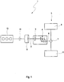
- the Figure 1 shows a schematic representation of a hybrid drive device 1, with an output shaft 2, which is connected, for example, via a clutch 3, in particular a starting clutch, and / or a transmission 4, in particular a gearbox, to an axle 5 of a motor vehicle not shown here.
- a clutch 3 in particular a starting clutch
- a transmission 4 in particular a gearbox
- an axle differential 7 On an output shaft 6 of the transmission 4 there is, for example, an axle differential 7 by means of which a torque provided on the output shaft 2 or the output shaft 6 is distributed to the wheels 8 of the axle 5 or the motor vehicle.
- the hybrid drive device 1 has a first drive unit 9 and a second drive unit 10.
- the first drive unit is arranged directly on the output shaft 2 of the hybrid drive device 1, that is, it is permanently operatively connected to it.
- the output shaft 2 and the second drive unit 10 there can be a separating clutch 11, by means of which the operative connection between the second drive unit 10 on the one hand and the output shaft 2 or the first drive unit 9 on the other hand can be interrupted or established.
- the first drive unit 9 is, for example, an electrical machine, while the second drive unit 10 is designed as an internal combustion engine.
- a drive torque of the hybrid drive device which is applied to the output shaft 2 is to be generated only by means of the first drive unit 9.
- a second operating mode it is provided to generate the drive torque jointly with the aid of the first drive unit 9 and the second drive unit 10, so that both each provide a non-zero portion of this drive torque.
- the separating clutch 11 is preferably opened, while in the second operating mode it is at least partially, in particular completely, closed. Complete closing is to be understood as meaning a state of the separating clutch 11 in which no clutch slip occurs.
- the second drive unit 10 is usually deactivated, that is, it has a speed of zero, or is operated at a low speed, in particular a speed that is lower than the speed of the first drive unit 9. In the latter embodiment, a possibly between the drive unit 9 and the output shaft 2 present translation are taken into account.
- an actual speed of the second drive unit 10 When switching from the first operating mode to the second operating mode, an actual speed of the second drive unit 10 must be matched to a setpoint speed. In the exemplary embodiment shown here, this target speed corresponds to the actual speed of the output shaft 2 or of the first drive unit 9.
- this target speed corresponds to the actual speed of the output shaft 2 or of the first drive unit 9.
- the target speed may have to be selected differently.
- the Figure 2 shows a block diagram of a method for operating the hybrid drive device 1.
- the hybrid drive device 1 is operated in the first operating mode, in which the drive torque is provided solely by means of the first drive unit 9.
- the second drive unit 10 is preferably deactivated.
- a setpoint speed gradient is determined, in particular on the basis of the driving dynamics level.
- query 14 can also be omitted and a constant setpoint speed gradient can always be used.
- a setpoint torque is determined from the setpoint speed gradient and set on the second drive unit 10.
- a regulation preferably takes place an actual speed gradient resulting from the actual speed of the second drive unit 10 to the previously selected target speed gradient. This is provided, for example, with the help of a P controller, which in this respect has a P control element.
- a pre-control can be provided in which the setpoint torque is determined from the moment of inertia of the second drive unit 10 and the setpoint speed gradient.
- operation 16 proceeds to operation 17.
- the second operating mode of the hybrid drive device 1 is present. It is now periodically checked within the scope of a query 18 whether the second operating mode should be continued or whether the second drive unit 10 should be uncoupled or deactivated. In the first case a branch is made to operation 17, in the latter case to operation 12. The method accordingly begins again from the beginning.
Description
Die Erfindung betrifft ein Verfahren zum Betreiben einer Hybridantriebseinrichtung mit einem ersten Antriebsaggregat und einem zweiten Antriebsaggregat, wobei ein Antriebsmoment der Hybridantriebseinrichtung in einer ersten Betriebsart nur mittels des ersten Antriebsaggregat und in einer zweiten Betriebsart von dem ersten Antriebsaggregat und dem zweiten Antriebsaggregat gemeinsam erzeugt wird, und wobei bei einem Umschalten von der ersten Betriebsart auf die zweite Betriebsart eine Istdrehzahl des zweiten Antriebsaggregats an eine Solldrehzahl angeglichen wird, die der Istdrehzahl des ersten Antriebsaggregats entspricht. Die Erfindung betrifft weiterhin eine Hybridantriebseinrichtung.The invention relates to a method for operating a hybrid drive unit with a first drive unit and a second drive unit, a drive torque of the hybrid drive unit being generated in a first mode only by means of the first drive unit and in a second mode of operation by the first drive unit and the second drive unit together, and wherein when switching from the first operating mode to the second operating mode, an actual speed of the second drive unit is matched to a target speed which corresponds to the actual speed of the first drive unit. The invention also relates to a hybrid drive device.
Die Hybridantriebseinrichtung weist wenigstens zwei Antriebsaggregate auf, nämlich das erste Antriebsaggregat und das zweite Antriebsaggregat. Als Antriebsaggregate können elektrische Maschinen, Brennkraftmaschinen oder dergleichen in beliebiger Kombination vorgesehen sein. Beispielsweise ist das erste Antriebsaggregat eine elektrische Maschine und das zweite Antriebsaggregat eine Brennkraftmaschine. In der ersten Betriebsart soll das Antriebsmoment allein mit Hilfe des ersten Antriebsaggregats erzeugt beziehungsweise bereitgestellt werden. Das bedeutet, dass das zweite Antriebsaggregat deaktiviert und/oder von dem ersten Antriebsaggregat abgekuppelt ist. Entsprechend liegt keine Wirkverbindung zwischen dem ersten Antriebsaggregat und dem zweiten Antriebsaggregat vor. Falls das erste Antriebsaggregat als elektrische Maschine ausgebildet ist, liegt insoweit in der ersten Betriebsart ein rein elektrischer Betrieb der Hybridantriebseinrichtung, insbesondere ein rein elektrisches Fahren eines Kraftfahrzeugs, welches die Hybridantriebseinrichtung aufweist, vor.The hybrid drive device has at least two drive units, namely the first drive unit and the second drive unit. Electrical machines, internal combustion engines or the like in any combination can be provided as drive units. For example, the first drive unit is an electrical machine and the second drive unit is an internal combustion engine. In the first operating mode, the drive torque should be generated or provided solely with the aid of the first drive unit. This means that the second drive unit is deactivated and / or decoupled from the first drive unit. Accordingly, there is no operative connection between the first drive unit and the second drive unit. If the first drive unit is designed as an electrical machine, the hybrid drive device is operated purely electrically in the first operating mode, in particular a motor vehicle that has the hybrid drive device is driven purely electrically.
In der zweiten Betriebsart sollen dagegen das erste Antriebsaggregat und das zweite Antriebsaggregat das Antriebsmoment gemeinsam erzeugen. Das bedeutet, dass sowohl das erste Antriebsaggregat als auch das zweite Antriebsaggregat jeweils einen von Null verschiedenen Anteil des Antriebsmoments bereitstellen. Üblicherweise ist jedoch in der ersten Betriebsart das zweite Antriebsaggregat deaktiviert oder weist zumindest eine geringe Drehzahl auf, insbesondere eine geringere Drehzahl als das erste Antriebsaggregat. Entsprechend ist es notwendig, die Istdrehzahl des zweiten Antriebsaggregats an die Solldrehzahl anzugleichen, wenn von der ersten Betriebsart auf die zweite Betriebsart umgeschaltet wird. Die Solldrehzahl ist bevorzugt diejenige Drehzahl, bei welcher das zweite Antriebsaggregat betrieben werden muss, um mit dem ersten Antriebsaggregat gekuppelt zu werden, insbesondere ohne Komforteinbußen. Beispielsweise entspricht die Solldrehzahl der Istdrehzahl des ersten Antriebsaggregats, insbesondere unter Berücksichtigung einer Übersetzung eines zwischen dem ersten Antriebsaggregat und dem zweiten Antriebsaggregat unter Umständen vorgesehenen Getriebes.In the second operating mode, on the other hand, the first drive unit and the second drive unit should generate the drive torque together. This means that both the first drive unit and the second drive unit each provide a non-zero portion of the drive torque. Usually, however, the second drive unit is deactivated in the first operating mode or has at least a low speed, in particular a lower speed than the first drive unit. Accordingly, it is necessary to set the actual speed of the second drive unit to adjust the target speed when switching from the first operating mode to the second operating mode. The set speed is preferably that speed at which the second drive unit must be operated in order to be coupled to the first drive unit, in particular without any loss of comfort. For example, the setpoint speed corresponds to the actual speed of the first drive unit, in particular taking into account a gear ratio of a transmission that may be provided between the first drive unit and the second drive unit.
Aus dem Stand der Technik ist beispielsweise die Druckschrift
Weiterhin ist die Druckschrift
Zudem beschreibt die Druckschrift
Die Druckschrift
Es ist nun Aufgabe der Erfindung, ein Verfahren zum Betreiben einer Hybridantriebseinrichtung vorzuschlagen welches Vorteile gegenüber dem Stand der Technik aufweist, insbesondere das Umschalten von der ersten Betriebsart auf die zweite Betriebsart schnell und mit hohem Komfort durchführen kann.It is now the object of the invention to propose a method for operating a hybrid drive device which has advantages over the prior art, in particular which can switch from the first operating mode to the second operating mode quickly and with great convenience.
Dies wird erfindungsgemäß mit einem Verfahren mit den Merkmalen des Anspruchs 1 erreicht. Dabei ist vorgesehen, dass zum Angleichen der Istdrehzahl einmalig zu Beginn des Angleichens ein Solldrehzahlgradient aus einer Mehrzahl von Solldrehzahlgradienten ausgewählt und ein anhand des Solldrehzahlgradienten bestimmtes Solldrehmoment an dem zweiten Antriebsaggregat eingestellt wird, wobei das Solldrehmoment mittels einer Regelung aus dem Solldrehzahlgradienten ermittelt wird, indem ein Istdrehzahlgradient auf den Solldrehzahlgradient geregelt wird, und wobei die Regelung eine Vorsteuerung umfasst, wobei das Solldrehmoment aus einem Trägheitsmoment des zweiten Antriebsaggregats und dem Solldrehzahlgradienten bestimmt wird.According to the invention, this is achieved with a method having the features of
Der Zustart des zweiten Antriebsaggregats, insbesondere der Brennkraftmaschine, wird bevorzugt situationsabhängig mit unterschiedlichen Anforderungen an Zuschaltdauer und Komfort vorgenommen. Ausschlaggebend für die Zuschaltdauer ist der Drehzahlgradient während des Angleichens der Istdrehzahl des zweiten Antriebsaggregats. Je größer der Drehzahlgradient ist, umso schneller wird die gewünschte Solldrehzahl durch die Istdrehzahl erreicht. Andererseits bewirkt ein kleiner Drehzahlgradient eine Erhöhung des Komforts, insbesondere wenn er, falls die Istdrehzahl die Solldrehzahl nahezu erreicht hat, vergleichsweise klein gewählt wird.The start-up of the second drive unit, in particular the internal combustion engine, is preferably carried out as a function of the situation with different requirements for connection duration and comfort. The speed gradient during the adjustment of the actual speed of the second drive unit is decisive for the connection duration. The greater the speed gradient, the faster the desired target speed is reached by the actual speed. On the other hand, a small speed gradient brings about an increase in comfort, in particular if it is selected to be comparatively small if the actual speed has almost reached the target speed.
Aus diesem Grund soll zunächst der Solldrehzahlgradient festgelegt werden, mittels welchem das Angleichen der Istdrehzahl an die Solldrehzahl erreicht werden kann beziehungsweise vorgenommen werden soll. Anhand dieses Solldrehzahlgradienten wird nachfolgend das Solldrehmoment ermittelt und an dem zweiten Antriebsaggregat eingestellt. Das Solldrehmoment liegt insoweit als Funktion von dem ausgewählten Solldrehzahlgradienten vor. Beispielsweise wird der Solldrehzahlgradient lediglich einmalig zu Beginn des Umschaltens ausgewählt und ist nachfolgend bis zum Beenden des Umschaltens, also bis zum Erreichen der zweiten Betriebsart beziehungsweise dem Erreichen der Solldrehzahl durch die Istdrehzahl, konstant. Durch das Ermitteln des Solldrehmoments aus dem Solldrehzahlgradienten ist dabei sichergestellt, dass das Angleichen der Istdrehzahl an die Solldrehzahl ausreichend rasch und mit hohem Komfort, also insbesondere ohne Ruckeln, vorgenommen werden kann. Selbstverständlich kann alternativ auch der Solldrehzahlgradient mehrfach bestimmt werden, beispielsweise in Abhängigkeit von der Istdrehzahl beziehungsweise der Differenz zwischen Solldrehzahl und Istdrehzahl.For this reason, the setpoint speed gradient should first be established, by means of which the adjustment of the actual speed to the setpoint speed can or should be achieved. On the basis of this target speed gradient, the target torque is then determined and set on the second drive unit. To this extent, the setpoint torque is available as a function of the selected setpoint speed gradient. For example, the target speed gradient is selected only once at the beginning of the switchover and is then constant until the switchover is ended, that is, until the second operating mode is reached or the actual speed reaches the target speed. By determining the setpoint torque from the setpoint speed gradient, it is ensured that the adjustment of the actual speed to the setpoint speed can be carried out sufficiently quickly and with a high level of comfort, that is to say in particular without jerking. Of course, the setpoint speed gradient can alternatively also be determined several times, for example as a function of the actual speed or the difference between the setpoint speed and the actual speed.
Nach dem Einstellen des Solldrehmoments an dem zweiten Antriebsaggregat wird dieses bevorzugt steuernd und/oder regelnd derart eingestellt, dass das Istdrehmoment dem Solldrehmoment entspricht. Bevorzugt ist eine Regelung des zweiten Antriebsaggregats beziehungsweise des Istdrehmoments des zweiten Antriebsaggregats auf das Solldrehmoment vorgesehen.After the setpoint torque has been set on the second drive unit, it is preferably set in a controlling and / or regulating manner such that the actual torque corresponds to the setpoint torque. Regulation of the second drive unit or the actual torque of the second drive unit to the setpoint torque is preferably provided.
Die Erfindung sieht vor, dass das Solldrehmoment mittels einer Regelung aus dem Solldrehzahlgradienten ermittelt wird. Das Solldrehmoment wird also derart eingestellt, dass der sich aus dem Istdrehmoment ergebende Istdrehzahlgradient dem Solldrehzahlgradient entspricht beziehungsweise sich diesem annähert. Der Solldrehzahlgradient entspricht insoweit einer Führungsgröße, das Solldrehmoment einer Stellgröße und das Istdrehmoment beziehungsweise der aus diesem ermittelte Istdrehzahlgradient einer Regelgröße eines Regelkreises der Hybridantriebseinrichtung. Aus dem Solldrehzahlgradient und dem Istdrehzahlgradient wird beispielsweise eine Regelabweichung ermittelt, welche insbesondere als Differenz zwischen dem Solldrehzahlgradient und dem Istdrehzahlgradient vorliegt. Diese Regelabweichung wird einem Regler beziehungsweise einem Regelglied der Regelung zugeführt. Diese ermittelt nachfolgend die notwendige Stellgröße beziehungsweise das notwendige Solldrehmoment, um den Istdrehzahlgradient auf den Solldrehzahlgradient zu regeln.The invention provides that the setpoint torque is determined from the setpoint speed gradient by means of a control system. The setpoint torque is therefore set in such a way that the actual speed gradient resulting from the actual torque corresponds to the setpoint speed gradient or approaches it. To this extent, the setpoint speed gradient corresponds to a reference variable, the setpoint torque to a manipulated variable and the actual torque or the actual speed gradient determined from this to a control variable of a control loop of the hybrid drive device. For example, a control deviation is determined from the setpoint speed gradient and the actual speed gradient, which is present in particular as the difference between the setpoint speed gradient and the actual speed gradient. This control deviation is fed to a controller or a control element of the control system. This then determines the required manipulated variable or the required target torque in order to regulate the actual speed gradient to the target speed gradient.
Eine bevorzugte Ausgestaltung der Erfindung sieht vor, dass die Regelung wenigstens ein P-Regelglied, I-Regelglied und/oder ein D-Regelglied aufweist. Die Regelung beziehungsweise der Regler verfügen über wenigstens ein Regelglied, welches die genannten Ausgestaltungen annehmen kann. Selbstverständlich können auch mehrere Regelglieder vorgesehen sein, sodass insoweit ein P-Regler, I-Regler, PI-Regler, PD-Regler oder PID-Regler vorliegt. Besonders bevorzugt ist lediglich ein P-Regelglied vorgesehen, sodass ein P-Regler realisiert ist. Alternativ sind sowohl ein P-Regelglied als auch ein I-Regelglied und mithin ein PI-Regler vorgesehen.A preferred embodiment of the invention provides that the control has at least one P control element, I control element and / or D control element. The regulation or the regulator have at least one regulating element which can take on the aforementioned configurations. It goes without saying that several control elements can also be provided, so that a P controller, I controller, PI controller, PD controller or PID controller is present. Particularly preferably, only one P control element is provided, so that a P controller is implemented. Alternatively, both a P control element and an I control element and therefore a PI controller are provided.
Die Erfindung sieht weiter vor, dass die Regelung eine Vorsteuerung umfasst, wobei das Solldrehmoment aus dem Trägheitsmoment und dem Solldrehzahlgradienten bestimmt wird. Neben dem Regler beziehungsweise dem wenigstens einen Regelglied ist also die Vorsteuerung vorgesehen, mittels welcher unabhängig von der Regelabweichung das Solldrehmoment gewählt wird. Besonders bevorzugt liegt das Solldrehmoment, welches aus der Vorsteuerung resultiert, als Funktion von dem Solldrehzahlgradienten vor. Als weitere Eingangsgröße, welche insbesondere konstant ist, wird das Trägheitsmoment, insbesondere des zweiten Antriebsaggregats, herangezogen. Der Solldrehzahlgradient kann im Rahmen der Vorsteuerung durch die Beziehung ![]()
![]()
Erfindungsgemäß ist vorgesehen, dass der Solldrehzahlgradient einmalig zu Beginn des Angleichens gewählt wird. Beispielsweise liegt der Solldrehzahlgradient als nicht veränderbare Konstante vor. Es kann jedoch auch vorgesehen sein, den Solldrehzahlgradienten aus einer Mehrzahl von Solldrehzahlgradienten zu Beginn des Angleichens auszuwählen. Beispielsweise umfasst die Mehrzahl der Solldrehzahlgradienten unterschiedliche Fahrdynamikstufen, wobei einer ersten Fahrdynamikstufe ein erster Solldrehzahlgradient, einer zweiten Fahrdynamikstufe ein zweiter Solldrehzahlgradient und einer dritten Fahrdynamikstufe ein dritter Solldrehzahlgradient zugeordnet, wobei der erste Solldrehzahlgradient kleiner als der zweite Solldrehzahlgradient ist und dieser wiederum kleiner als der dritte Solldrehzahlgradient. Insoweit ist die erste Fahrdynamikstufe eine Komfortstufe, die zweite Fahrdynamikstufe eine Dynamikstufe und die dritte Fahrdynamikstufe eine Sportstufe. Der Solldrehzahlgradient wird beispielsweise während des gesamten Angleichens, also bis zum vollständigen Umschalten von der ersten Betriebsart auf die zweite Betriebsart beibehalten.According to the invention it is provided that the setpoint speed gradient is selected once at the start of the equalization. For example, the setpoint speed gradient is available as a constant that cannot be changed. However, it can also be provided that the setpoint speed gradient is selected from a plurality of setpoint speed gradients at the beginning of the equalization. For example, the plurality of target speed gradients includes different driving dynamics levels, with a first driving dynamics level being assigned a first target speed gradient, a second driving dynamics level being assigned a second target speed gradient and a third driving dynamics level being assigned a third target speed gradient, the first target speed gradient being smaller than the second target speed gradient and this in turn being smaller than the third target speed gradient . In this respect, the first driving dynamics level is a comfort level, the second driving dynamics level is a dynamic level and the third driving dynamics level is a sport level. The setpoint speed gradient is retained, for example, during the entire equalization, that is to say until the complete switchover from the first operating mode to the second operating mode.
Die Erfindung betrifft weiterhin eine Hybridantriebseinrichtung, insbesondere zur Durchführung des Verfahrens gemäß den vorstehenden Ausführungen, mit einem ersten Antriebsaggregat und einem zweiten Antriebsaggregat, wobei die Hybridantriebseinrichtung dazu ausgebildet ist, ein Antriebsmoment der Hybridantriebseinrichtung in einer ersten Betriebsart nur mittels des ersten Antriebsaggregats und in einer zweiten Betriebsart mittels des ersten Antriebsaggregats und des zweiten Antriebsaggregats gemeinsam zu erzeugen, wobei bei einem Umschalten von der ersten Betriebsart auf die zweite Betriebsart eine Istdrehzahl des zweiten Antriebsaggregats an eine Solldrehzahl angeglichen wird, die der Istdrehzahl des ersten Antriebsaggregats entspricht. Dabei ist vorgesehen, dass die Hybridantriebseinrichtung dazu ausgebildet ist, zum Angleichen der Istdrehzahl einmalig zu Beginn des Angleichens einen Solldrehzahlgradient aus einer Mehrzahl von Solldrehzahlgradienten auszuwählen und ein anhand des Solldrehzahlgradienten bestimmtes Solldrehmoment an dem zweiten Antriebsaggregat einzustellen, wobei das Solldrehmoment mittels einer Regelung aus dem Solldrehzahlgradienten ermittelt wird, indem ein Istdrehzahlgradient auf den Solldrehzahlgradient geregelt wird, und wobei die Regelung eine Vorsteuerung umfasst, wobei das Solldrehmoment aus einem Trägheitsmoment des zweiten Antriebsaggregats und dem Solldrehzahlgradienten bestimmt wird. Auf die Vorteile einer derartigen Ausgestaltung der Hybridantriebseinrichtung beziehungsweise einer derartigen Vorgehensweise wurde bereits hingewiesen. Die Hybridantriebseinrichtung und das Verfahren können gemäß den vorstehenden Ausführungen weitergebildet sein, sodass insoweit auf diese verwiesen wird.The invention further relates to a hybrid drive device, in particular for carrying out the method according to the above statements, with a first drive unit and a second drive unit, the hybrid drive device being designed to generate a drive torque of the hybrid drive device in a first operating mode only by means of the first drive unit and in a second Generate operating mode by means of the first drive unit and the second drive unit together, wherein when switching from the first operating mode to the second operating mode, an actual speed of the second drive unit is adjusted to a target speed that corresponds to the actual speed of the first drive unit. It is provided that the hybrid drive device is designed to adjust the actual speed once at the beginning of the adjustment to select a setpoint speed gradient from a plurality of setpoint speed gradients and to set a setpoint torque determined on the basis of the setpoint speed gradient on the second drive unit, the setpoint torque being controlled from the setpoint speed gradient is determined by regulating an actual speed gradient to the setpoint speed gradient, and wherein the control comprises a pilot control, the setpoint torque from a moment of inertia of the second drive unit and the setpoint speed gradient is determined. Reference has already been made to the advantages of such a configuration of the hybrid drive device or such a procedure. The hybrid drive device and the method can be developed in accordance with the above statements, so that reference is made to them in this respect.
Die Erfindung wird nachfolgend anhand der in der Zeichnung dargestellten Ausführungsbeispiele näher erläutert, ohne dass eine Beschränkung der Erfindung erfolgt. Dabei zeigt:
Figur 1- eine schematische Darstellung einer Hybridantriebseinrichtung, und
Figur 2- ein Blockschaltbild eines Verfahrens zum Betreiben der Hybridantriebseinrichtung.
- Figure 1
- a schematic representation of a hybrid drive device, and
- Figure 2
- a block diagram of a method for operating the hybrid drive device.
Die
Die Hybridantriebseinrichtung 1 verfügt über ein erstes Antriebsaggregat 9 sowie ein zweites Antriebsaggregat 10. Beispielsweise ist das erste Antriebsaggregat unmittelbar auf der Abtriebswelle 2 der Hybridantriebseinrichtung 1 angeordnet, also permanent mit dieser wirkverbunden. In der Wirkverbindung zwischen der Abtriebswelle 2 und dem zweiten Antriebsaggregat 10 kann eine Trennkupplung 11 vorliegen, mittels welcher die Wirkverbindung zwischen dem zweiten Antriebsaggregat 10 einerseits sowie der Abtriebswelle 2 beziehungsweise dem ersten Antriebsaggregat 9 andererseits unterbrochen oder hergestellt werden kann. Das erste Antriebsaggregat 9 liegt beispielsweise als elektrische Maschine vor, während das zweite Antriebsaggregat 10 als Brennkraftmaschine ausgeführt ist.The
In einer ersten Betriebsart der Hybridantriebseinrichtung soll nun ein Antriebsmoment der Hybridantriebseinrichtung, welches an der Abtriebswelle 2 anliegt, nur mittels des ersten Antriebsaggregats 9 erzeugt werden. In einer zweiten Betriebsart ist es dagegen vorgesehen, das Antriebsmoment mit Hilfe des ersten Antriebsaggregats 9 und des zweiten Antriebsaggregats 10 gemeinsam zu erzeugen, sodass beide jeweils einen von Null verschiedenen Anteil dieses Antriebsmoments bereitstellen. In der ersten Betriebsart ist insoweit die Trennkupplung 11 bevorzugt geöffnet, während sie in der zweiten Betriebsart zumindest teilweise, insbesondere vollständig, geschlossen ist. Unter dem vollständigen Schließen ist dabei ein Zustand der Trennkupplung 11 zu verstehen, in welchem kein Kupplungsschlupf auftritt.In a first operating mode of the hybrid drive device, a drive torque of the hybrid drive device, which is applied to the
In der ersten Betriebsart ist das zweite Antriebsaggregat 10 üblicherweise deaktiviert, weist also eine Drehzahl von Null auf, oder wird allenfalls mit einer geringen Drehzahl betrieben, insbesondere einer Drehzahl, welche kleiner ist als die Drehzahl des ersten Antriebsaggregats 9. Bei letzterer Ausführungsform muss selbstverständlich eine unter Umständen zwischen dem Antriebsaggregat 9 und der Abtriebswelle 2 vorliegende Übersetzung berücksichtigt werden. Bei einem Umschalten von der ersten Betriebsart auf die zweite Betriebsart muss eine Istdrehzahl des zweiten Antriebsaggregats 10 an eine Solldrehzahl angeglichen werden. Bei dem hier dargestellten Ausführungsbeispiel entspricht diese Solldrehzahl der Istdrehzahl der Abtriebswelle 2 beziehungsweise des ersten Antriebsaggregats 9. Selbstverständlich sind jedoch auch andere Ausführungsformen realisierbar, bei welchen unter Umständen die Solldrehzahl anders gewählt werden muss.In the first operating mode, the
Die
Nachfolgend wird in einer Operation 15 ein Solldrehzahlgradient ermittelt, insbesondere anhand der Fahrdynamikstufe. Selbstverständlich kann die Abfrage 14 auch entfallen und stets ein konstanter Solldrehzahlgradient verwendet werden. Nachfolgend wird im Rahmen einer Operation 16 aus dem Solldrehzahlgradienten ein Solldrehmoment ermittelt und an dem zweiten Antriebsaggregat 10 eingestellt. Bevorzugt erfolgt dabei ein Regeln eines sich aus der Istdrehzahl des zweiten Antriebsaggregats 10 ergebenden Istdrehzahlgradienten auf den zuvor ausgewählten Solldrehzahlgradienten. Dies ist beispielsweise mit Hilfe eines P-Reglers vorgesehen, welcher insoweit über ein P-Regelglied verfügt.Subsequently, in an
Zudem kann eine Vorsteuerung vorgesehen sein, bei welcher das Solldrehmoment aus dem Trägheitsmoment des zweiten Antriebsaggregats 10 und dem Solldrehzahlgradienten ermittelt wird. Sobald die Istdrehzahl des zweiten Antriebsaggregats 10 die Solldrehzahl erreicht hat, wird aus der Operation 16 zu der Operation 17 fortgeschritten. In dieser liegt insoweit die zweite Betriebsart der Hybridantriebseinrichtung 1 vor. Periodisch wird nun im Rahmen einer Abfrage 18 überprüft, ob die zweite Betriebsart fortgeführt werden soll oder ob das zweite Antriebsaggregat 10 abgekuppelt beziehungsweise deaktiviert werden soll. In erstem Fall wird zu der Operation 17 verzweigt, in letzterem zu der Operation 12. Entsprechend beginnt das Verfahren erneut von Beginn an.In addition, a pre-control can be provided in which the setpoint torque is determined from the moment of inertia of the
Mit Hilfe des vorstehend beschriebenen Verfahrens ist ein äußerst rasches, jedoch gleichzeitig komfortables Angleichen der Istdrehzahl des zweiten Antriebsaggregats 10 an die Solldrehzahl möglich. Insbesondere ist es nicht notwendig, mit Kennfeldern dasjenige Solldrehmoment zu ermitteln, mit welchem der gewünschte Drehzahlgradient zumindest näherungsweise erhalten werden kann. Vielmehr ist stattdessen eine Regelung des Istdrehzahlgradienten auf den Solldrehzahlgradienten vorgesehen. Zumindest wird jedoch das Solldrehmoment aus dem zuvor ausgewählten Solldrehzahlgradienten bestimmt und anschließend an dem zweiten Antriebsaggregat 10 eingestellt.With the aid of the method described above, it is possible to adapt the actual speed of the
- 11
- HybridantriebseinrichtungHybrid propulsion device
- 22
- AbtriebswelleOutput shaft
- 33
- Kupplungcoupling
- 44th
- Getriebetransmission
- 55
- Achseaxis
- 66th
- AusgangswelleOutput shaft
- 77th
- AchsdifferentialAxle differential
- 88th
- Radwheel
- 99
- 1. Antriebsaggregat1. Drive unit
- 1010
- 2. Antriebsaggregat2. Drive unit
- 1111
- TrennkupplungDisconnect clutch
- 1212
- Operationsurgery
- 1313
- Abfragequery
- 1414th
- Abfragequery
- 1515th
- Operationsurgery
- 1616
- Operationsurgery
- 1717th
- Operationsurgery
- 1818th
- Abfragequery
Claims (3)
- Method for operating a hybrid drive apparatus (1) having a first drive unit (9) and a second drive unit (10), wherein a drive torque of the hybrid drive apparatus (1) is produced only by means of the first drive unit (9) in a first operating mode and is produced jointly by the first drive unit (9) and the second drive unit (10) in a second operating mode, and wherein an actual rotational speed of the second drive unit (10) is brought into line with a target rotational speed upon a switchover from the first operating mode to the second operating mode, which corresponds to the actual rotational speed of the first drive unit (9), characterised in that, in order to bring the actual rotational speed into line, once at the beginning of bringing into line, a target rotational speed gradient is selected from a plurality of target rotational speed gradients and a target torque, determined on the basis of the target rotational speed gradients, is set at the second drive unit (10), wherein the target torque is determined by means of a control from the target rotational speed gradients, while an actual rotational speed gradient is controlled on the target rotational speed gradient, and wherein the control comprises a pre-control, wherein the target torque is determined on the basis of a moment of inertia of the second drive unit and the target rotational speed gradients.
- Method according to claim 1, characterised in that the control has at least a P-control element, an I-control element and/or a D-control element.
- Hybrid drive apparatus(1), in particular for implementing the method according to one or more of the preceding claims, having a first drive unit (9) and a second drive unit (10), wherein the hybrid drive apparatus (1) is designed to produce a drive torque of the hybrid drive apparatus (1) only by means of the first drive unit (9) in a first operating mode and jointly by means of the first drive unit (9) and the second drive unit (10) in a second operating mode, wherein an actual rotational speed of the second drive unit (10) is brought line with a target rotational speed upon a switchover from the first operating mode to the second operating mode, which corresponds to the actual rotational speed of the first drive unit (9), characterised in that the hybrid drive apparatus (1) is designed, in order to bring the actual rotational speed into line, once at the beginning of bringing into line, to select a target rotational speed gradient from a plurality of target rotational speed gradients and to set a target torque determined on the basis of the target rotational speed gradients at the second drive unit (10), wherein the target torque is determined by means of a control from the target rotational speed gradients, while an actual rotational speed gradient is controlled on the target rotational speed gradient, and wherein the control comprises a pre-control, wherein the target torque is determined on the basis of a moment of inertia of the second drive unit and the target rotational speed gradients.
Applications Claiming Priority (2)
| Application Number | Priority Date | Filing Date | Title |
|---|---|---|---|
| DE102013017946.7A DE102013017946B8 (en) | 2013-10-29 | 2013-10-29 | Method for operating a hybrid drive device and corresponding hybrid drive device |
| PCT/EP2014/002903 WO2015062721A2 (en) | 2013-10-29 | 2014-10-29 | Method for operating a hybrid drive device and corresponding hybrid drive device |
Publications (2)
| Publication Number | Publication Date |
|---|---|
| EP3063032A2 EP3063032A2 (en) | 2016-09-07 |
| EP3063032B1 true EP3063032B1 (en) | 2021-01-13 |
Family
ID=51951769
Family Applications (1)
| Application Number | Title | Priority Date | Filing Date |
|---|---|---|---|
| EP14802591.9A Active EP3063032B1 (en) | 2013-10-29 | 2014-10-29 | Method for operating a hybrid drive device and corresponding hybrid drive device |
Country Status (6)
| Country | Link |
|---|---|
| US (1) | US9758152B2 (en) |
| EP (1) | EP3063032B1 (en) |
| JP (1) | JP2016540693A (en) |
| CN (1) | CN105683014B (en) |
| DE (1) | DE102013017946B8 (en) |
| WO (1) | WO2015062721A2 (en) |
Families Citing this family (2)
| Publication number | Priority date | Publication date | Assignee | Title |
|---|---|---|---|---|
| KR102281654B1 (en) * | 2017-06-08 | 2021-07-29 | 현대자동차주식회사 | Hybrid vehicle and method for controlling thereof |
| WO2019146401A1 (en) * | 2018-01-29 | 2019-08-01 | トヨタ自動車株式会社 | Control device for hybrid vehicles |
Citations (1)
| Publication number | Priority date | Publication date | Assignee | Title |
|---|---|---|---|---|
| DE102008036166A1 (en) * | 2008-08-02 | 2010-02-04 | Daimler Ag | Method for controlling operation of hybrid vehicle, particularly change from electric motor operation to hybrid operation and from hybrid operation to electric motor operation, involves starting internal combustion engine |
Family Cites Families (22)
| Publication number | Priority date | Publication date | Assignee | Title |
|---|---|---|---|---|
| US6581705B2 (en) * | 2001-06-29 | 2003-06-24 | Ford Global Technologies, Llc | Method for starting an engine in a parallel hybrid electric vehicle |
| WO2006132020A1 (en) * | 2005-06-07 | 2006-12-14 | Aisin Aw Co., Ltd. | Hybrid drive device |
| JP5371200B2 (en) * | 2006-05-24 | 2013-12-18 | 日産自動車株式会社 | An engine start control device for a hybrid vehicle and an engine start control method for a hybrid vehicle. |
| US7691021B2 (en) * | 2006-06-09 | 2010-04-06 | Hyundai Motor Company | Power train for hybrid electric vehicles and method of controlling the same |
| DE102006031684A1 (en) * | 2006-07-08 | 2008-01-10 | Zf Friedrichshafen Ag | Motor vehicle hybrid drive, with an automatic gearbox, closes the clutch between the motors when starting the combustion motor while driving with the electromotor |
| KR100815307B1 (en) * | 2006-08-08 | 2008-03-19 | 현대자동차주식회사 | Power Delivery Apparatus for Hybrid Vehicle |
| DE102006054740A1 (en) | 2006-11-21 | 2008-06-12 | Dr.Ing.H.C. F. Porsche Ag | Method and device for switching on an internal combustion engine in a hybrid vehicle drive |
| JP2009051401A (en) * | 2007-08-28 | 2009-03-12 | Denso Corp | Control device and control system for vehicle |
| DE102008002383A1 (en) * | 2008-06-12 | 2009-12-17 | Zf Friedrichshafen Ag | Method for controlling a hybrid powertrain |
| DE102008002382A1 (en) * | 2008-06-12 | 2009-12-17 | Zf Friedrichshafen Ag | Method for controlling a hybrid powertrain |
| DE102008064291A1 (en) * | 2008-12-20 | 2010-07-15 | Volkswagen Ag | Vehicle i.e. hybrid vehicle, has electrical machine indirectly connected with transmission, where electrical machine and internal-combustion engine are connected by separation clutch i.e. dosed proportional clutch, in detachable manner |
| JP5170569B2 (en) * | 2009-03-31 | 2013-03-27 | アイシン・エィ・ダブリュ株式会社 | Hybrid drive device |
| DE102010030800A1 (en) * | 2010-07-01 | 2012-01-05 | Bayerische Motoren Werke Aktiengesellschaft | Method for computation of time-dependent sequences of two parameters during rotation speed change in e.g. motor car, involves computing two time-dependent sequences based on target rotational speed parameter or its change |
| US8618752B2 (en) * | 2010-07-21 | 2013-12-31 | Superior Electron, Llc | System, architecture, and method for minimizing power consumption and increasing performance in electric vehicles |
| DE112010005907T5 (en) * | 2010-09-27 | 2013-07-18 | Toyota Jidosha Kabushiki Kaisha | Control device for a hybrid vehicle |
| JP5382467B2 (en) * | 2011-04-20 | 2014-01-08 | アイシン・エィ・ダブリュ株式会社 | Vehicle drive device |
| JP2012254739A (en) * | 2011-06-09 | 2012-12-27 | Toyota Motor Corp | Control device of hybrid vehicle |
| JP5807560B2 (en) * | 2011-07-06 | 2015-11-10 | アイシン・エィ・ダブリュ株式会社 | Control device |
| US20140180522A1 (en) * | 2011-08-11 | 2014-06-26 | Toyota Jidosha Kabushiki Kaisha | Hybrid vehicle control device |
| WO2013102945A1 (en) * | 2012-01-04 | 2013-07-11 | トヨタ自動車株式会社 | Vehicle control device |
| DE102012003020A1 (en) * | 2012-02-15 | 2013-08-22 | Audi Ag | Control system for speed control of a drive motor |
| DE102012018222B4 (en) * | 2012-09-14 | 2016-11-10 | Audi Ag | Method and control system for the electronic control of the speed of at least one drive motor of a motor vehicle |
-
2013
- 2013-10-29 DE DE102013017946.7A patent/DE102013017946B8/en not_active Expired - Fee Related
-
2014
- 2014-10-29 EP EP14802591.9A patent/EP3063032B1/en active Active
- 2014-10-29 JP JP2016550951A patent/JP2016540693A/en active Pending
- 2014-10-29 CN CN201480059233.7A patent/CN105683014B/en active Active
- 2014-10-29 US US15/032,762 patent/US9758152B2/en active Active
- 2014-10-29 WO PCT/EP2014/002903 patent/WO2015062721A2/en active Application Filing
Patent Citations (1)
| Publication number | Priority date | Publication date | Assignee | Title |
|---|---|---|---|---|
| DE102008036166A1 (en) * | 2008-08-02 | 2010-02-04 | Daimler Ag | Method for controlling operation of hybrid vehicle, particularly change from electric motor operation to hybrid operation and from hybrid operation to electric motor operation, involves starting internal combustion engine |
Also Published As
| Publication number | Publication date |
|---|---|
| DE102013017946B8 (en) | 2015-07-30 |
| US9758152B2 (en) | 2017-09-12 |
| CN105683014A (en) | 2016-06-15 |
| US20160339899A1 (en) | 2016-11-24 |
| DE102013017946A1 (en) | 2015-04-30 |
| WO2015062721A3 (en) | 2015-09-03 |
| JP2016540693A (en) | 2016-12-28 |
| EP3063032A2 (en) | 2016-09-07 |
| WO2015062721A2 (en) | 2015-05-07 |
| DE102013017946B4 (en) | 2015-07-16 |
| CN105683014B (en) | 2018-05-01 |
Similar Documents
| Publication | Publication Date | Title |
|---|---|---|
| EP2665632B1 (en) | Method and device for operating a drive device | |
| AT515103B1 (en) | METHOD FOR STARTING AN INTERNAL COMBUSTION ENGINE | |
| WO2008043590A1 (en) | Method for operating a parallel hybrid drive | |
| DE102015208402A1 (en) | Method and control device for operating a drive train | |
| WO2017202419A1 (en) | Method for operating a drivetrain of a hybrid vehicle, and drivetrain of a hybrid vehicle | |
| DE102015004118A1 (en) | Method for operating a drive device for a motor vehicle and corresponding drive device | |
| DE102017216392A1 (en) | Method and control device for operating a motor vehicle | |
| EP3063032B1 (en) | Method for operating a hybrid drive device and corresponding hybrid drive device | |
| EP3351449B1 (en) | Method for operating a drive device for a motor vehicle and corresponding drive device | |
| DE102013226611A1 (en) | Method for operating a hybrid drive device | |
| DE102012224211A1 (en) | Method for operating hybrid car, involves adjusting objective rotation speed of combustion engine based on operating point of drive unit if actual rotation speed of combustion engine reaches target rotation speed or tolerance range | |
| DE102013200825A1 (en) | Method for operating hybrid vehicle e.g. motor car, involves determining time sequence for closing between engine and electrical machine, and between switched clutch and switching element based on operating point of drive unit | |
| DE102006020934B4 (en) | Drive train device of a vehicle | |
| EP3075620B1 (en) | Method for performing a gear change in parallel hybrid vehicles | |
| DE10138998A1 (en) | Device for controlling shift process for load switchable gearbox controls couplings with which gearbox input shaft speed can be adjusted superimposed on output shaft torque adjustment | |
| DE102017200783A1 (en) | Method for operating a drive train and control device of a motor vehicle | |
| EP3351446B1 (en) | Method for operating a drive device for a motor vehicle and corresponding drive device | |
| WO2010057731A1 (en) | Method for detecting a developing torque for a hybrid drive | |
| DE102017200786A1 (en) | Method and control device for operating a motor vehicle | |
| DE102018119273A1 (en) | Method for restarting a drive element in a drive train | |
| WO2010112257A1 (en) | Method and apparatus for operating a hybrid vehicle | |
| DE102012104506B4 (en) | Method and device for speed control of a drive device of a motor vehicle and corresponding control element for activating and deactivating the method | |
| EP3669097B1 (en) | Method for calibrating a drive system for an axle of a motor vehicle | |
| DE102016203434A1 (en) | Method for adapting a gripping point of a separating clutch for a vehicle | |
| DE102014209395A1 (en) | Method for reducing drag torque fluctuations during electrical starting |
Legal Events
| Date | Code | Title | Description |
|---|---|---|---|
| PUAI | Public reference made under article 153(3) epc to a published international application that has entered the european phase |
Free format text: ORIGINAL CODE: 0009012 |
|
| 17P | Request for examination filed |
Effective date: 20160530 |
|
| AK | Designated contracting states |
Kind code of ref document: A2 Designated state(s): AL AT BE BG CH CY CZ DE DK EE ES FI FR GB GR HR HU IE IS IT LI LT LU LV MC MK MT NL NO PL PT RO RS SE SI SK SM TR |
|
| AX | Request for extension of the european patent |
Extension state: BA ME |
|
| DAX | Request for extension of the european patent (deleted) | ||
| STAA | Information on the status of an ep patent application or granted ep patent |
Free format text: STATUS: EXAMINATION IS IN PROGRESS |
|
| 17Q | First examination report despatched |
Effective date: 20190509 |
|
| GRAP | Despatch of communication of intention to grant a patent |
Free format text: ORIGINAL CODE: EPIDOSNIGR1 |
|
| STAA | Information on the status of an ep patent application or granted ep patent |
Free format text: STATUS: GRANT OF PATENT IS INTENDED |
|
| INTG | Intention to grant announced |
Effective date: 20201105 |
|
| GRAS | Grant fee paid |
Free format text: ORIGINAL CODE: EPIDOSNIGR3 |
|
| GRAA | (expected) grant |
Free format text: ORIGINAL CODE: 0009210 |
|
| STAA | Information on the status of an ep patent application or granted ep patent |
Free format text: STATUS: THE PATENT HAS BEEN GRANTED |
|
| AK | Designated contracting states |
Kind code of ref document: B1 Designated state(s): AL AT BE BG CH CY CZ DE DK EE ES FI FR GB GR HR HU IE IS IT LI LT LU LV MC MK MT NL NO PL PT RO RS SE SI SK SM TR |
|
| REG | Reference to a national code |
Ref country code: GB Ref legal event code: FG4D Free format text: NOT ENGLISH |
|
| REG | Reference to a national code |
Ref country code: CH Ref legal event code: EP |
|
| REG | Reference to a national code |
Ref country code: DE Ref legal event code: R096 Ref document number: 502014015199 Country of ref document: DE |
|
| REG | Reference to a national code |
Ref country code: IE Ref legal event code: FG4D Free format text: LANGUAGE OF EP DOCUMENT: GERMAN |
|
| REG | Reference to a national code |
Ref country code: AT Ref legal event code: REF Ref document number: 1354294 Country of ref document: AT Kind code of ref document: T Effective date: 20210215 |
|
| REG | Reference to a national code |
Ref country code: NL Ref legal event code: MP Effective date: 20210113 |
|
| REG | Reference to a national code |
Ref country code: LT Ref legal event code: MG9D |
|
| PG25 | Lapsed in a contracting state [announced via postgrant information from national office to epo] |
Ref country code: GR Free format text: LAPSE BECAUSE OF FAILURE TO SUBMIT A TRANSLATION OF THE DESCRIPTION OR TO PAY THE FEE WITHIN THE PRESCRIBED TIME-LIMIT Effective date: 20210414 Ref country code: HR Free format text: LAPSE BECAUSE OF FAILURE TO SUBMIT A TRANSLATION OF THE DESCRIPTION OR TO PAY THE FEE WITHIN THE PRESCRIBED TIME-LIMIT Effective date: 20210113 Ref country code: FI Free format text: LAPSE BECAUSE OF FAILURE TO SUBMIT A TRANSLATION OF THE DESCRIPTION OR TO PAY THE FEE WITHIN THE PRESCRIBED TIME-LIMIT Effective date: 20210113 Ref country code: PT Free format text: LAPSE BECAUSE OF FAILURE TO SUBMIT A TRANSLATION OF THE DESCRIPTION OR TO PAY THE FEE WITHIN THE PRESCRIBED TIME-LIMIT Effective date: 20210513 Ref country code: LT Free format text: LAPSE BECAUSE OF FAILURE TO SUBMIT A TRANSLATION OF THE DESCRIPTION OR TO PAY THE FEE WITHIN THE PRESCRIBED TIME-LIMIT Effective date: 20210113 Ref country code: BG Free format text: LAPSE BECAUSE OF FAILURE TO SUBMIT A TRANSLATION OF THE DESCRIPTION OR TO PAY THE FEE WITHIN THE PRESCRIBED TIME-LIMIT Effective date: 20210413 Ref country code: NL Free format text: LAPSE BECAUSE OF FAILURE TO SUBMIT A TRANSLATION OF THE DESCRIPTION OR TO PAY THE FEE WITHIN THE PRESCRIBED TIME-LIMIT Effective date: 20210113 Ref country code: NO Free format text: LAPSE BECAUSE OF FAILURE TO SUBMIT A TRANSLATION OF THE DESCRIPTION OR TO PAY THE FEE WITHIN THE PRESCRIBED TIME-LIMIT Effective date: 20210413 |
|
| PG25 | Lapsed in a contracting state [announced via postgrant information from national office to epo] |
Ref country code: PL Free format text: LAPSE BECAUSE OF FAILURE TO SUBMIT A TRANSLATION OF THE DESCRIPTION OR TO PAY THE FEE WITHIN THE PRESCRIBED TIME-LIMIT Effective date: 20210113 Ref country code: RS Free format text: LAPSE BECAUSE OF FAILURE TO SUBMIT A TRANSLATION OF THE DESCRIPTION OR TO PAY THE FEE WITHIN THE PRESCRIBED TIME-LIMIT Effective date: 20210113 Ref country code: LV Free format text: LAPSE BECAUSE OF FAILURE TO SUBMIT A TRANSLATION OF THE DESCRIPTION OR TO PAY THE FEE WITHIN THE PRESCRIBED TIME-LIMIT Effective date: 20210113 Ref country code: SE Free format text: LAPSE BECAUSE OF FAILURE TO SUBMIT A TRANSLATION OF THE DESCRIPTION OR TO PAY THE FEE WITHIN THE PRESCRIBED TIME-LIMIT Effective date: 20210113 |
|
| PG25 | Lapsed in a contracting state [announced via postgrant information from national office to epo] |
Ref country code: IS Free format text: LAPSE BECAUSE OF FAILURE TO SUBMIT A TRANSLATION OF THE DESCRIPTION OR TO PAY THE FEE WITHIN THE PRESCRIBED TIME-LIMIT Effective date: 20210513 |
|
| REG | Reference to a national code |
Ref country code: DE Ref legal event code: R097 Ref document number: 502014015199 Country of ref document: DE |
|
| PG25 | Lapsed in a contracting state [announced via postgrant information from national office to epo] |
Ref country code: CZ Free format text: LAPSE BECAUSE OF FAILURE TO SUBMIT A TRANSLATION OF THE DESCRIPTION OR TO PAY THE FEE WITHIN THE PRESCRIBED TIME-LIMIT Effective date: 20210113 Ref country code: EE Free format text: LAPSE BECAUSE OF FAILURE TO SUBMIT A TRANSLATION OF THE DESCRIPTION OR TO PAY THE FEE WITHIN THE PRESCRIBED TIME-LIMIT Effective date: 20210113 Ref country code: SM Free format text: LAPSE BECAUSE OF FAILURE TO SUBMIT A TRANSLATION OF THE DESCRIPTION OR TO PAY THE FEE WITHIN THE PRESCRIBED TIME-LIMIT Effective date: 20210113 |
|
| PLBE | No opposition filed within time limit |
Free format text: ORIGINAL CODE: 0009261 |
|
| STAA | Information on the status of an ep patent application or granted ep patent |
Free format text: STATUS: NO OPPOSITION FILED WITHIN TIME LIMIT |
|
| PG25 | Lapsed in a contracting state [announced via postgrant information from national office to epo] |
Ref country code: RO Free format text: LAPSE BECAUSE OF FAILURE TO SUBMIT A TRANSLATION OF THE DESCRIPTION OR TO PAY THE FEE WITHIN THE PRESCRIBED TIME-LIMIT Effective date: 20210113 Ref country code: SK Free format text: LAPSE BECAUSE OF FAILURE TO SUBMIT A TRANSLATION OF THE DESCRIPTION OR TO PAY THE FEE WITHIN THE PRESCRIBED TIME-LIMIT Effective date: 20210113 Ref country code: DK Free format text: LAPSE BECAUSE OF FAILURE TO SUBMIT A TRANSLATION OF THE DESCRIPTION OR TO PAY THE FEE WITHIN THE PRESCRIBED TIME-LIMIT Effective date: 20210113 Ref country code: ES Free format text: LAPSE BECAUSE OF FAILURE TO SUBMIT A TRANSLATION OF THE DESCRIPTION OR TO PAY THE FEE WITHIN THE PRESCRIBED TIME-LIMIT Effective date: 20210113 |
|
| 26N | No opposition filed |
Effective date: 20211014 |
|
| PG25 | Lapsed in a contracting state [announced via postgrant information from national office to epo] |
Ref country code: AL Free format text: LAPSE BECAUSE OF FAILURE TO SUBMIT A TRANSLATION OF THE DESCRIPTION OR TO PAY THE FEE WITHIN THE PRESCRIBED TIME-LIMIT Effective date: 20210113 |
|
| PG25 | Lapsed in a contracting state [announced via postgrant information from national office to epo] |
Ref country code: SI Free format text: LAPSE BECAUSE OF FAILURE TO SUBMIT A TRANSLATION OF THE DESCRIPTION OR TO PAY THE FEE WITHIN THE PRESCRIBED TIME-LIMIT Effective date: 20210113 |
|
| PG25 | Lapsed in a contracting state [announced via postgrant information from national office to epo] |
Ref country code: IT Free format text: LAPSE BECAUSE OF FAILURE TO SUBMIT A TRANSLATION OF THE DESCRIPTION OR TO PAY THE FEE WITHIN THE PRESCRIBED TIME-LIMIT Effective date: 20210113 |
|
| REG | Reference to a national code |
Ref country code: CH Ref legal event code: PL |
|
| PG25 | Lapsed in a contracting state [announced via postgrant information from national office to epo] |
Ref country code: IS Free format text: LAPSE BECAUSE OF FAILURE TO SUBMIT A TRANSLATION OF THE DESCRIPTION OR TO PAY THE FEE WITHIN THE PRESCRIBED TIME-LIMIT Effective date: 20210513 |
|
| REG | Reference to a national code |
Ref country code: BE Ref legal event code: MM Effective date: 20211031 |
|
| PG25 | Lapsed in a contracting state [announced via postgrant information from national office to epo] |
Ref country code: MC Free format text: LAPSE BECAUSE OF FAILURE TO SUBMIT A TRANSLATION OF THE DESCRIPTION OR TO PAY THE FEE WITHIN THE PRESCRIBED TIME-LIMIT Effective date: 20210113 |
|
| PG25 | Lapsed in a contracting state [announced via postgrant information from national office to epo] |
Ref country code: LU Free format text: LAPSE BECAUSE OF NON-PAYMENT OF DUE FEES Effective date: 20211029 Ref country code: BE Free format text: LAPSE BECAUSE OF NON-PAYMENT OF DUE FEES Effective date: 20211031 |
|
| PG25 | Lapsed in a contracting state [announced via postgrant information from national office to epo] |
Ref country code: LI Free format text: LAPSE BECAUSE OF NON-PAYMENT OF DUE FEES Effective date: 20211031 Ref country code: CH Free format text: LAPSE BECAUSE OF NON-PAYMENT OF DUE FEES Effective date: 20211031 |
|
| PG25 | Lapsed in a contracting state [announced via postgrant information from national office to epo] |
Ref country code: IE Free format text: LAPSE BECAUSE OF NON-PAYMENT OF DUE FEES Effective date: 20211029 |
|
| REG | Reference to a national code |
Ref country code: AT Ref legal event code: MM01 Ref document number: 1354294 Country of ref document: AT Kind code of ref document: T Effective date: 20211029 |
|
| PGFP | Annual fee paid to national office [announced via postgrant information from national office to epo] |
Ref country code: FR Payment date: 20221021 Year of fee payment: 9 |
|
| PG25 | Lapsed in a contracting state [announced via postgrant information from national office to epo] |
Ref country code: AT Free format text: LAPSE BECAUSE OF NON-PAYMENT OF DUE FEES Effective date: 20211029 |
|
| PGFP | Annual fee paid to national office [announced via postgrant information from national office to epo] |
Ref country code: GB Payment date: 20221019 Year of fee payment: 9 Ref country code: DE Payment date: 20221031 Year of fee payment: 9 |
|
| PG25 | Lapsed in a contracting state [announced via postgrant information from national office to epo] |
Ref country code: HU Free format text: LAPSE BECAUSE OF FAILURE TO SUBMIT A TRANSLATION OF THE DESCRIPTION OR TO PAY THE FEE WITHIN THE PRESCRIBED TIME-LIMIT; INVALID AB INITIO Effective date: 20141029 |
|
| PG25 | Lapsed in a contracting state [announced via postgrant information from national office to epo] |
Ref country code: CY Free format text: LAPSE BECAUSE OF FAILURE TO SUBMIT A TRANSLATION OF THE DESCRIPTION OR TO PAY THE FEE WITHIN THE PRESCRIBED TIME-LIMIT Effective date: 20210113 |
|
| P01 | Opt-out of the competence of the unified patent court (upc) registered |
Effective date: 20230530 |