EP3669097B1 - Method for calibrating a drive system for an axle of a motor vehicle - Google Patents
Method for calibrating a drive system for an axle of a motor vehicle Download PDFInfo
- Publication number
- EP3669097B1 EP3669097B1 EP17758829.0A EP17758829A EP3669097B1 EP 3669097 B1 EP3669097 B1 EP 3669097B1 EP 17758829 A EP17758829 A EP 17758829A EP 3669097 B1 EP3669097 B1 EP 3669097B1
- Authority
- EP
- European Patent Office
- Prior art keywords
- clutch
- torque
- drive
- drive unit
- output shaft
- Prior art date
- Legal status (The legal status is an assumption and is not a legal conclusion. Google has not performed a legal analysis and makes no representation as to the accuracy of the status listed.)
- Active
Links
- 238000000034 method Methods 0.000 title claims description 45
- 230000005540 biological transmission Effects 0.000 claims description 16
- 238000010586 diagram Methods 0.000 claims description 15
- 230000001419 dependent effect Effects 0.000 claims description 8
- 238000012937 correction Methods 0.000 description 17
- 230000008878 coupling Effects 0.000 description 8
- 238000010168 coupling process Methods 0.000 description 8
- 238000005859 coupling reaction Methods 0.000 description 8
- 238000013519 translation Methods 0.000 description 7
- 230000001105 regulatory effect Effects 0.000 description 6
- FGUUSXIOTUKUDN-IBGZPJMESA-N C1(=CC=CC=C1)N1C2=C(NC([C@H](C1)NC=1OC(=NN=1)C1=CC=CC=C1)=O)C=CC=C2 Chemical compound C1(=CC=CC=C1)N1C2=C(NC([C@H](C1)NC=1OC(=NN=1)C1=CC=CC=C1)=O)C=CC=C2 FGUUSXIOTUKUDN-IBGZPJMESA-N 0.000 description 3
- 239000013598 vector Substances 0.000 description 3
- 230000006978 adaptation Effects 0.000 description 2
- 239000012530 fluid Substances 0.000 description 2
- 241001261858 Alsodes Species 0.000 description 1
- 238000013459 approach Methods 0.000 description 1
- 238000013461 design Methods 0.000 description 1
- 238000011161 development Methods 0.000 description 1
- 230000018109 developmental process Effects 0.000 description 1
- 230000000694 effects Effects 0.000 description 1
- 230000007935 neutral effect Effects 0.000 description 1
- 230000000737 periodic effect Effects 0.000 description 1
- 239000013589 supplement Substances 0.000 description 1
- 238000012360 testing method Methods 0.000 description 1
Images

Classifications
-
- F—MECHANICAL ENGINEERING; LIGHTING; HEATING; WEAPONS; BLASTING
- F16—ENGINEERING ELEMENTS AND UNITS; GENERAL MEASURES FOR PRODUCING AND MAINTAINING EFFECTIVE FUNCTIONING OF MACHINES OR INSTALLATIONS; THERMAL INSULATION IN GENERAL
- F16D—COUPLINGS FOR TRANSMITTING ROTATION; CLUTCHES; BRAKES
- F16D48/00—External control of clutches
- F16D48/06—Control by electric or electronic means, e.g. of fluid pressure
-
- B—PERFORMING OPERATIONS; TRANSPORTING
- B60—VEHICLES IN GENERAL
- B60W—CONJOINT CONTROL OF VEHICLE SUB-UNITS OF DIFFERENT TYPE OR DIFFERENT FUNCTION; CONTROL SYSTEMS SPECIALLY ADAPTED FOR HYBRID VEHICLES; ROAD VEHICLE DRIVE CONTROL SYSTEMS FOR PURPOSES NOT RELATED TO THE CONTROL OF A PARTICULAR SUB-UNIT
- B60W50/00—Details of control systems for road vehicle drive control not related to the control of a particular sub-unit, e.g. process diagnostic or vehicle driver interfaces
- B60W50/06—Improving the dynamic response of the control system, e.g. improving the speed of regulation or avoiding hunting or overshoot
-
- B—PERFORMING OPERATIONS; TRANSPORTING
- B60—VEHICLES IN GENERAL
- B60W—CONJOINT CONTROL OF VEHICLE SUB-UNITS OF DIFFERENT TYPE OR DIFFERENT FUNCTION; CONTROL SYSTEMS SPECIALLY ADAPTED FOR HYBRID VEHICLES; ROAD VEHICLE DRIVE CONTROL SYSTEMS FOR PURPOSES NOT RELATED TO THE CONTROL OF A PARTICULAR SUB-UNIT
- B60W10/00—Conjoint control of vehicle sub-units of different type or different function
- B60W10/02—Conjoint control of vehicle sub-units of different type or different function including control of driveline clutches
- B60W10/023—Fluid clutches
-
- B—PERFORMING OPERATIONS; TRANSPORTING
- B60—VEHICLES IN GENERAL
- B60W—CONJOINT CONTROL OF VEHICLE SUB-UNITS OF DIFFERENT TYPE OR DIFFERENT FUNCTION; CONTROL SYSTEMS SPECIALLY ADAPTED FOR HYBRID VEHICLES; ROAD VEHICLE DRIVE CONTROL SYSTEMS FOR PURPOSES NOT RELATED TO THE CONTROL OF A PARTICULAR SUB-UNIT
- B60W10/00—Conjoint control of vehicle sub-units of different type or different function
- B60W10/04—Conjoint control of vehicle sub-units of different type or different function including control of propulsion units
- B60W10/08—Conjoint control of vehicle sub-units of different type or different function including control of propulsion units including control of electric propulsion units, e.g. motors or generators
-
- B—PERFORMING OPERATIONS; TRANSPORTING
- B60—VEHICLES IN GENERAL
- B60W—CONJOINT CONTROL OF VEHICLE SUB-UNITS OF DIFFERENT TYPE OR DIFFERENT FUNCTION; CONTROL SYSTEMS SPECIALLY ADAPTED FOR HYBRID VEHICLES; ROAD VEHICLE DRIVE CONTROL SYSTEMS FOR PURPOSES NOT RELATED TO THE CONTROL OF A PARTICULAR SUB-UNIT
- B60W2510/00—Input parameters relating to a particular sub-units
- B60W2510/02—Clutches
-
- B—PERFORMING OPERATIONS; TRANSPORTING
- B60—VEHICLES IN GENERAL
- B60W—CONJOINT CONTROL OF VEHICLE SUB-UNITS OF DIFFERENT TYPE OR DIFFERENT FUNCTION; CONTROL SYSTEMS SPECIALLY ADAPTED FOR HYBRID VEHICLES; ROAD VEHICLE DRIVE CONTROL SYSTEMS FOR PURPOSES NOT RELATED TO THE CONTROL OF A PARTICULAR SUB-UNIT
- B60W2510/00—Input parameters relating to a particular sub-units
- B60W2510/08—Electric propulsion units
- B60W2510/081—Speed
-
- B—PERFORMING OPERATIONS; TRANSPORTING
- B60—VEHICLES IN GENERAL
- B60W—CONJOINT CONTROL OF VEHICLE SUB-UNITS OF DIFFERENT TYPE OR DIFFERENT FUNCTION; CONTROL SYSTEMS SPECIALLY ADAPTED FOR HYBRID VEHICLES; ROAD VEHICLE DRIVE CONTROL SYSTEMS FOR PURPOSES NOT RELATED TO THE CONTROL OF A PARTICULAR SUB-UNIT
- B60W2510/00—Input parameters relating to a particular sub-units
- B60W2510/08—Electric propulsion units
- B60W2510/083—Torque
-
- B—PERFORMING OPERATIONS; TRANSPORTING
- B60—VEHICLES IN GENERAL
- B60W—CONJOINT CONTROL OF VEHICLE SUB-UNITS OF DIFFERENT TYPE OR DIFFERENT FUNCTION; CONTROL SYSTEMS SPECIALLY ADAPTED FOR HYBRID VEHICLES; ROAD VEHICLE DRIVE CONTROL SYSTEMS FOR PURPOSES NOT RELATED TO THE CONTROL OF A PARTICULAR SUB-UNIT
- B60W2510/00—Input parameters relating to a particular sub-units
- B60W2510/08—Electric propulsion units
- B60W2510/085—Power
-
- F—MECHANICAL ENGINEERING; LIGHTING; HEATING; WEAPONS; BLASTING
- F16—ENGINEERING ELEMENTS AND UNITS; GENERAL MEASURES FOR PRODUCING AND MAINTAINING EFFECTIVE FUNCTIONING OF MACHINES OR INSTALLATIONS; THERMAL INSULATION IN GENERAL
- F16D—COUPLINGS FOR TRANSMITTING ROTATION; CLUTCHES; BRAKES
- F16D2500/00—External control of clutches by electric or electronic means
- F16D2500/10—System to be controlled
- F16D2500/104—Clutch
- F16D2500/10406—Clutch position
- F16D2500/10412—Transmission line of a vehicle
-
- F—MECHANICAL ENGINEERING; LIGHTING; HEATING; WEAPONS; BLASTING
- F16—ENGINEERING ELEMENTS AND UNITS; GENERAL MEASURES FOR PRODUCING AND MAINTAINING EFFECTIVE FUNCTIONING OF MACHINES OR INSTALLATIONS; THERMAL INSULATION IN GENERAL
- F16D—COUPLINGS FOR TRANSMITTING ROTATION; CLUTCHES; BRAKES
- F16D2500/00—External control of clutches by electric or electronic means
- F16D2500/10—System to be controlled
- F16D2500/106—Engine
- F16D2500/1066—Hybrid
-
- F—MECHANICAL ENGINEERING; LIGHTING; HEATING; WEAPONS; BLASTING
- F16—ENGINEERING ELEMENTS AND UNITS; GENERAL MEASURES FOR PRODUCING AND MAINTAINING EFFECTIVE FUNCTIONING OF MACHINES OR INSTALLATIONS; THERMAL INSULATION IN GENERAL
- F16D—COUPLINGS FOR TRANSMITTING ROTATION; CLUTCHES; BRAKES
- F16D2500/00—External control of clutches by electric or electronic means
- F16D2500/30—Signal inputs
- F16D2500/302—Signal inputs from the actuator
- F16D2500/3024—Pressure
-
- F—MECHANICAL ENGINEERING; LIGHTING; HEATING; WEAPONS; BLASTING
- F16—ENGINEERING ELEMENTS AND UNITS; GENERAL MEASURES FOR PRODUCING AND MAINTAINING EFFECTIVE FUNCTIONING OF MACHINES OR INSTALLATIONS; THERMAL INSULATION IN GENERAL
- F16D—COUPLINGS FOR TRANSMITTING ROTATION; CLUTCHES; BRAKES
- F16D2500/00—External control of clutches by electric or electronic means
- F16D2500/30—Signal inputs
- F16D2500/302—Signal inputs from the actuator
- F16D2500/3027—Torque
-
- F—MECHANICAL ENGINEERING; LIGHTING; HEATING; WEAPONS; BLASTING
- F16—ENGINEERING ELEMENTS AND UNITS; GENERAL MEASURES FOR PRODUCING AND MAINTAINING EFFECTIVE FUNCTIONING OF MACHINES OR INSTALLATIONS; THERMAL INSULATION IN GENERAL
- F16D—COUPLINGS FOR TRANSMITTING ROTATION; CLUTCHES; BRAKES
- F16D2500/00—External control of clutches by electric or electronic means
- F16D2500/30—Signal inputs
- F16D2500/304—Signal inputs from the clutch
- F16D2500/3041—Signal inputs from the clutch from the input shaft
- F16D2500/30415—Speed of the input shaft
-
- F—MECHANICAL ENGINEERING; LIGHTING; HEATING; WEAPONS; BLASTING
- F16—ENGINEERING ELEMENTS AND UNITS; GENERAL MEASURES FOR PRODUCING AND MAINTAINING EFFECTIVE FUNCTIONING OF MACHINES OR INSTALLATIONS; THERMAL INSULATION IN GENERAL
- F16D—COUPLINGS FOR TRANSMITTING ROTATION; CLUTCHES; BRAKES
- F16D2500/00—External control of clutches by electric or electronic means
- F16D2500/30—Signal inputs
- F16D2500/304—Signal inputs from the clutch
- F16D2500/3042—Signal inputs from the clutch from the output shaft
- F16D2500/30426—Speed of the output shaft
-
- F—MECHANICAL ENGINEERING; LIGHTING; HEATING; WEAPONS; BLASTING
- F16—ENGINEERING ELEMENTS AND UNITS; GENERAL MEASURES FOR PRODUCING AND MAINTAINING EFFECTIVE FUNCTIONING OF MACHINES OR INSTALLATIONS; THERMAL INSULATION IN GENERAL
- F16D—COUPLINGS FOR TRANSMITTING ROTATION; CLUTCHES; BRAKES
- F16D2500/00—External control of clutches by electric or electronic means
- F16D2500/50—Problem to be solved by the control system
- F16D2500/502—Relating the clutch
- F16D2500/50245—Calibration or recalibration of the clutch touch-point
- F16D2500/50251—During operation
-
- F—MECHANICAL ENGINEERING; LIGHTING; HEATING; WEAPONS; BLASTING
- F16—ENGINEERING ELEMENTS AND UNITS; GENERAL MEASURES FOR PRODUCING AND MAINTAINING EFFECTIVE FUNCTIONING OF MACHINES OR INSTALLATIONS; THERMAL INSULATION IN GENERAL
- F16D—COUPLINGS FOR TRANSMITTING ROTATION; CLUTCHES; BRAKES
- F16D2500/00—External control of clutches by electric or electronic means
- F16D2500/50—Problem to be solved by the control system
- F16D2500/502—Relating the clutch
- F16D2500/50245—Calibration or recalibration of the clutch touch-point
- F16D2500/50266—Way of detection
- F16D2500/50281—Transmitted torque
-
- F—MECHANICAL ENGINEERING; LIGHTING; HEATING; WEAPONS; BLASTING
- F16—ENGINEERING ELEMENTS AND UNITS; GENERAL MEASURES FOR PRODUCING AND MAINTAINING EFFECTIVE FUNCTIONING OF MACHINES OR INSTALLATIONS; THERMAL INSULATION IN GENERAL
- F16D—COUPLINGS FOR TRANSMITTING ROTATION; CLUTCHES; BRAKES
- F16D2500/00—External control of clutches by electric or electronic means
- F16D2500/70—Details about the implementation of the control system
- F16D2500/702—Look-up tables
- F16D2500/70205—Clutch actuator
- F16D2500/70217—Pressure
-
- F—MECHANICAL ENGINEERING; LIGHTING; HEATING; WEAPONS; BLASTING
- F16—ENGINEERING ELEMENTS AND UNITS; GENERAL MEASURES FOR PRODUCING AND MAINTAINING EFFECTIVE FUNCTIONING OF MACHINES OR INSTALLATIONS; THERMAL INSULATION IN GENERAL
- F16D—COUPLINGS FOR TRANSMITTING ROTATION; CLUTCHES; BRAKES
- F16D2500/00—External control of clutches by electric or electronic means
- F16D2500/70—Details about the implementation of the control system
- F16D2500/702—Look-up tables
- F16D2500/70252—Clutch torque
Definitions
- the present invention relates to a method for calibrating a drive system for an axle of a motor vehicle.
- the drive system comprises at least one electric machine as the drive unit, a drive shaft driven by the drive unit, a first output shaft and a second output shaft as well as a first coupling connecting the drive shaft to the first output shaft and a second coupling connecting the drive shaft to the second output shaft.
- a control unit is also provided for regulating the drive unit and the clutches and for determining the rotational speeds of the drive shaft and the output shafts.
- the clutches are assigned to the output shafts on a common axis.
- Such drive systems are z. B. provided for the forwarding and needs-based distribution of a torque provided by the drive unit.
- the clutches used are usually calibrated as part of an end-of-line test before being put into operation for the first time, so that a control unit can actuate the clutches depending on the operating point.
- the state or (optimal) operating point of the clutches can change over the course of the operating time, e.g. B. as a result of Vcrschlciß.
- the further applied actuation pressures of the clutches originally required to transmit a torque can result in the transmission or distribution of the torque calculated by the control unit no longer taking place or no longer taking place in accordance with the desired specifications.
- a new calibration of the couplings, e.g. B. as part of a workshop visit is then required. Such a visit to the workshop is undesirable because it is inconvenient for the user of the vehicle.
- the object of the present invention to at least partially solve the disadvantages and problems mentioned at the beginning and in particular to propose a method suitable for this (re) calibration of a drive system (during operation).
- the method is intended to make it possible that, depending on a first torque provided by the drive unit, a correct actuation pressure is applied to the clutches predominantly or even at any point in time during operation of the drive system. This is intended to enable the fastest and most precise transmission and distribution of the first torque via the couplings to the wheels of an axle over the running time.
- the method for calibration relates in particular to the regulation of the clutches of the drive system, so that they are checked or actuated at predetermined times or even at any time by a calibrated actuation pressure and thus a first torque provided by the drive unit in the desired manner on the wheels of a common axle of the motor vehicle can be transmitted.
- the method for regulating a drive system in which two clutches are provided on a common axle of the motor vehicle, one wheel of the motor vehicle being connected to the drive unit of the motor vehicle in a torque-transmitting manner via each of the two clutches.
- the two clutches can replace the otherwise common differential, which can be used to compensate for different speeds of the wheels.
- multi-disk clutches are used as clutches in which the outer disks are rotatably connected to an outer disk carrier and inner disks with an inner disk carrier and each disk carrier is rotatably connected to the drive shaft or the respective output shaft.
- a closing force acting in an axial direction as a result of the actuation pressure
- the disks, in other clutches the friction partners are brought into contact with one another, so that a torque can be transmitted from the drive shaft via the coupling to the respective output shaft.
- the actuation pressure of the respective clutch required for the transmission of a first torque of the drive unit can be unknown. Further z. B. in the course of the operation of the drive system, the actuation pressure of the clutch required for the transmission of the first torque (and / or the torque divided between the first clutch and the second clutch). In particular, the actuation pressure and / or its change can be different for the first clutch and the second clutch.
- a “calibration” here comprises in particular a reliably reproducible determination and documentation of the deviation of the desired and actually transmitted torques.
- a correction can be included as a further process, taking into account the determined deviation during the subsequent use of the drive system. This can further lead to an integrated adjustment and / or adjustment of the control of the drive unit if, for. B. the detected deviation is unacceptably high. After each adjustment, the control of the drive unit can be checked again in order to check the changes made.
- a first torque is provided by the drive unit and, based on an operating point (which is defined, for example, by a request from a driver of the motor vehicle), is transmitted to the wheels and, if necessary, divided.
- a first torque is provided on the drive unit for a specifiable operating point.
- This can e.g. B. generated by the drive unit on the basis of a request from a driver of the motor vehicle, e.g. B. by pressing a pedal.
- the operating point can be predetermined in such a way that the torques are to be distributed unevenly on the output shafts.
- both clutches transmit the same amount of torque but a desired total torque is incorrect, it can also be useful to correct both clutches in the same way, as explained below, until the total torque is correct.
- the average error can also be reduced in this case, even if the distribution of the torques between the two clutches does not necessarily improve significantly.
- a first actuation pressure for the first clutch and a second actuation pressure for the second clutch are determined from a first characteristic map.
- the two actuation pressures are intended to bring about an operating point-dependent transmission and distribution of the first torque to the two output shafts (possibly taking into account a translation between the drive unit and the output shafts).
- the first torque can also be divided into unequal proportions, e.g. B. due to different traction conditions on the wheels, due to cornering and / or due to an active chassis control (“torque control" ), in which the torques are essentially freely distributed to the wheels depending on a desired driving behavior (understeer, oversteer, neutral) can.
- a first target torque is to be transmitted via the first clutch and a second target torque is to be transmitted via the second clutch, the target torques being the sum of the first one provided by the drive unit Torque, especially taking into account a translation between the drive unit and the output shafts.
- respectively specified actuation pressures can be stored or predetermined for different operating points and first torques, which are to be applied to the clutches for transmission and, if necessary, division of the first torque.
- the two clutches can, for. B. due to wear and / or a calibration that has not yet been carried out during the initial start-up of the drive system, deviations occur in the desired or specified application of the actuating pressures. These deviations are expressed by the actual differential speeds that can be determined.
- step c) a first actual differential speed between the first output shaft and the drive shaft and a second actual differential speed between the second output shaft and the drive shaft are determined.
- the slip between the at least one output shaft and the drive shaft can generate frictional heat in the clutch. This can at least damage the Lead clutch. If the actuation pressure is too high, it cannot be ensured that the torque provided by the drive unit will be transmitted to the output shafts in the desired manner and distribution.
- the actual differential speeds as well as the speeds of the drive unit can be determined by means of the control unit. This can e.g. B. determine the drive shaft speed and the speeds of the output shafts via speed sensors.
- a setpoint differential speed between the two output shafts and the drive shaft is specified.
- This so-called micro-slip on the respective clutches makes it possible to determine exactly what kind of torque is transmitted over both clutches in total.
- the setpoint differential speed is particularly dependent on the operating point and is present or is set in this way at a constant drive shaft speed and constant speed of the output shafts.
- step d1) the following process d1) can be carried out: setting a first calibrated actuation pressure for the first clutch until a first setpoint differential speed is reached, and setting a second calibrated actuation pressure for the second clutch until a second setpoint differential speed is reached .
- step d2) the following process d2) can be carried out: Setting a first calibrated torque on the drive unit until a first setpoint differential speed is reached on the first clutch and a second setpoint differential speed on the second clutch.
- the actuation pressures or the first torque on the drive unit are - provided there is an undesired deviation - up or down based on the actual differential speed determined in step c) and applied to the clutch until a predetermined target differential speed is applied to the respective clutch is present.
- Steps c) and d) can be carried out iteratively until a predefined setpoint differential speed is present at the respective clutch.
- a proportional change in the actuation pressures is not made here, but rather only when the operating point in step a) requires an equal distribution of the first torque to the clutches.
- the creation of the new map can be done arithmetically, with which in particular the calculation of a corrector vector / map and / or the continuous multiplication of the previous map with a determined correction vector is recorded.
- the creation of the new map can take place in such a way that an already stored map is selected and / or activated as a function of the determined deviation.
- the second map replaces in particular that first map, so that when the drive system is subsequently actuated, even when steps a) and b) are carried out, the second map can be accessed.
- the calibrated actuation pressures from the second map replace the actuation pressures from the first map.
- the first characteristic diagram can be replaced by the second characteristic diagram, so that a new first characteristic diagram is available.
- the first torque to be transmitted can be determined at least from the electrical motor current applied to the electrical machine.
- the first operating pressure applied in step b) can correspond to a first torque that can theoretically be transmitted to the first clutch, and the second operating pressure can correspond to a second torque that can theoretically be transmitted to the second clutch.
- Step c) can be used to detect a discrepancy between a total target torque to be transmitted jointly by both clutches (sum of first and second target torque) and a theoretically transmittable total torque (sum of theoretically transmittable first and second torque). This deviation can be corrected by setting the calibrated actuation pressures or the calibrated first torque on the drive axle according to step d). This deviation is taken into account when creating the second characteristic diagram.
- the theoretically transferable torque is in particular a torque assigned to the applied operating pressure in accordance with the existing characteristic diagram.
- the sum of the theoretically transmittable torques can accordingly have a deviation from the first torque provided by the drive unit (and thus a deviation from a sum of the first setpoint torque and the second setpoint torque). This deviation can be determined on the basis of the differential speeds in step c) and can now be corrected (for example iteratively) and / or its extent determined by a calibration in accordance with step d).
- the characteristics map can be created or modified in step e).
- the proposed method is set up in such a way that it is assumed that the greater part of the error or the deviation of the total torque is present in the clutch with the stronger actuation (that is, the clutch with the higher actuation pressure). It is therefore proposed in particular to adjust the actuation pressure of this clutch stored in the characteristic map first (and alone) or (when both actuation pressures change) to a greater extent than the actuation pressure of the weaker actuated clutch.
- This adaptation of the first characteristic map can generally take place by means of correction factors, especially for specific operating points by means of correction vectors or correction characteristic maps, or by creating a new characteristic map.
- step c) With each subsequent actuation or with each subsequent implementation of the method, it can be determined again whether there is a discrepancy between the sum of the theoretically transmittable torques and the (then applied) first torque is present. This can be verified in step c) by determining the differential speeds.
- At least one of the two clutches can be a hydraulically operated clutch, preferably both clutches.
- the operating pressure is transmitted to the clutch via a hydraulic fluid.
- the hydraulic fluid can be pressurized by a pump (which can also be operated electrically).
- At least one of the two clutches can be an electrically operated clutch, preferably both clutches.
- the operating pressure is generated directly by an electric machine, e.g. B. by a rotatable on the machine ramp arrangement.
- At least one electrical motor current and a motor speed of the drive unit are detected by means of the control unit.
- the motor speed of the drive unit can be determined via the drive shaft speed of the drive shaft or vice versa.
- steps a) to e) are carried out continuously. This means in particular that every time steps a) to d) are carried out, step e) is also carried out. Continuous accordingly means in particular that step e) is always initiated in predefinable operating points or driving situations.
- steps a) to e) are carried out periodically (at predetermined times). I. E. in particular that steps a) to d) are carried out several times in succession without step e) being at least initiated.
- a period is determined as a function of at least one of the following parameters: the time, the operating time of the drive system, the more or less intensive stress on the drive system.
- a period can span one or more days, or between 10 hours and 100 hours of operation. The period can be variable in particular as a function of the stress on the drive system.
- one wheel of the common axle of the motor vehicle can be connected to the drive unit in a torque-transmitting manner.
- At least one clutch is preferred, in particular both clutches are a multi-disc clutch.
- a gear with a variable transmission ratio can be arranged between the drive unit and the output shafts.
- Variable translation means in particular that there is not a single constant translation, but that the translation can be changed, e.g. B. in stages or continuously.
- no gear or a gear with a single fixed gear ratio can be arranged between the drive unit and the output shafts.
- the two clutches for the transmission of torques are arranged on an axle of a motor vehicle, so that by actuating the first clutch a first wheel of an axle and by actuating the second clutch a second wheel of the same axle of the motor vehicle is connected to the drive unit in a torque-transmitting manner.
- the clutches are therefore in particular not a motor vehicle clutch which is arranged between the drive unit and a switchable transmission of the motor vehicle.
- Such couplings which are arranged jointly on an axle, must (often) process sudden changes in a first torque and pass this on to the wheels in a predetermined manner.
- a constant or periodic adaptation of the characteristics map when the motor vehicle is in operation is therefore particularly advantageous.
- first primarily (only) serve to distinguish between several similar objects, sizes or processes, i.e. in particular no dependency and / or sequence of these objects, sizes or prescribe processes to each other. Should a dependency and / or sequence be required this is explicitly stated here or it is obvious to the person skilled in the art when studying the specifically described embodiment.
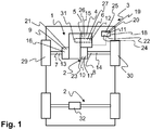
- Fig. 1 shows a motor vehicle 3 with a drive system 1 for driving a first wheel 29 and a second wheel 30 of a common axle 2 of the motor vehicle 3.
- the drive system 1 comprises an electric machine 4 as the drive unit 5, a drive shaft 6 driven by the drive unit 5, a first output shaft 7 and a second output shaft 8 as well as a first coupling 9 connecting the drive shaft 6 to the first output shaft 7 and a second coupling 10 connecting the drive shaft 6 to the second output shaft 8 and the two clutches 9, 10 and for determining speeds 12, 13, 14 of the drive shaft 6 and the two output shafts 7, 8.
- a drive system 1 is shown in which two clutches 9, 10 are provided on a common axle 2 of the motor vehicle 3, with one wheel 29, 30 of the motor vehicle 3 connected to the drive unit 5 of the motor vehicle 3 via each of the two clutches 9, 10 Is connected to transmit torque.
- the two clutches 9, 10 replace an otherwise common differential 32 (shown here on the other axle of the motor vehicle), by means of which different speeds of the wheels can be compensated.
- the calibration method relates to the regulation of the clutches 9, 10 of the drive system 1, so that they can be actuated at any time by a calibrated actuation pressure 21, 23. In this way, a first torque 15 provided by the drive unit 5 can be transmitted in the desired manner (and distribution) to the wheels 29, 30 of a common axle 2 of the motor vehicle 3.
- a calibration of the actuation pressure 16, 17, 21, 23 is also possible during the operation of the drive system 1.
- a first torque 15 is provided by the drive unit 5 and this is transmitted (proportionally) to the wheels 29, 30 on the basis of an existing operating point (which is defined, for example, by a request from a driver of the motor vehicle 3).
- a first torque 15 is provided on the drive unit 5.
- This can e.g. B. generated by the drive unit on the basis of a request from a driver of the motor vehicle 3.
- a first actuation pressure 16 for the first clutch 9 and a second actuation pressure 17 for the second clutch 10 are determined in the control unit 11 from a first characteristic map 18.
- the actuation pressures 16, 17 are intended to effect an operating point-dependent transmission and distribution of the first torque 15 to the output shafts 7, 8.
- the first torque 15 can also be divided up differently. Different actuation pressures 16, 17 can be stored in the first characteristic map 18 for different operating points and first torques 15, which are to be applied to the clutches 9, 10 for the transmission and, if necessary, the division of the first torque 15.
- a first actual differential speed 19 between the first output shaft 7 and the drive shaft 6 and a second actual differential speed 20 between the second output shaft 8 and the drive shaft 6 are determined.
- These actual differential speeds 19, 20 allow a conclusion to be drawn about the set and actually applied actuation pressures of the clutches 9, 10. If the actuation pressure is too high, the actual differential speed 19, 20 is "0" revolutions per minute. If the actuation pressure is too low, the actual differential speed 19, 20 will be not equal to "0" revolutions per minute and in particular be lower than a predetermined setpoint differential speed 22, 24.
- the drive shaft speed 12 is higher than the first speed 13 or second speed 14 of the respective output shaft 7, 8.
- the actual differential speeds 19, 20 as well as the speed of the drive unit 5 are determined via the control unit 11. This can determine the drive shaft speed 12 and the speeds 13, 14 of the output shafts 7, 8 via speed sensors.
- a setpoint differential speed 22, 24 between the output shafts 7, 8 and the drive shaft 6 is specified. This so-called micro-slip on the respective clutches 9, 10 makes it possible to determine exactly what kind of torque is transmitted in total via the clutches 9, 10. However, it is not possible to draw conclusions about the actual distribution of the first torque 15 to the clutches 9, 10.
- This setpoint differential speed 22, 24 is particularly dependent on the operating point and is present at a constant drive shaft speed 12 and constant speed 13, 14 of the output shafts 7, 8.
- the applied actuation pressures 16, 17 that are too high or too low correspond to a first torque 35 theoretically transmittable on the first clutch 9 (according to first characteristic map 18) and a second torque 36 theoretically transmittable on the second clutch 10 (according to first characteristic map 18).
- the sum of the theoretically transmittable torques 39 can accordingly have a deviation from the first torque 15 provided by the drive unit 5. This deviation can now be corrected by a calibration according to step d).
- step d) a first calibrated actuation pressure 21 for the first clutch 9 can be set until a first setpoint differential speed 22 is reached and a second calibrated actuation pressure 23 for the second clutch 10 is set until a second setpoint differential speed 24 is reached .
- the actuation pressure is therefore regulated up or down, taking into account the actual differential speed 19, 20 determined in step c), and is applied to the clutch 9, 10 is applied until a predetermined setpoint differential speed 22, 24 is present at the respective clutch 9, 10.
- a second characteristic map 25 is created taking into account the calibrated actuation pressures 21, 23 or the calibrated first torque on the drive unit 5.
- the second characteristic map 25 replaces in particular the first characteristic map 18, so that when the drive system 1 is subsequently actuated, even when steps a) and b) are carried out, the second characteristic map 25 can be accessed.
- the corrected actuation pressures from the newly created or second characteristic map 25 thus replace the actuation pressures 16, 17 from the first characteristic map 18.
- the first characteristic diagram 18 can be replaced by the second characteristic diagram 25, so that a new first characteristic diagram 18 is available.
- the second characteristic map 25 can be created by way of example and simply by multiplying first correction factors 40 for the first clutch 9 and second correction factors 41 for the second clutch 10 by the first characteristic map 18.
- the first torque 15 to be transmitted can be determined at least from the electric motor current 26 applied to the electric machine 4.
- At least one electrical motor current 26 and a motor speed 27 of the drive unit 5 are detected via the control unit 11.
- the motor speed 27 of the drive unit 5 can be determined via the drive shaft speed 12 of the drive shaft 6 or vice versa.
- Fig. 2 shows a sequence of the method. On the remarks too Fig. 1 is referred to.
- a first torque 15 is provided on the drive unit 5.
- step b) a first actuation pressure 16 for the first clutch 9 and a second actuation pressure 17 for the second clutch 10 are determined in the control unit 11 from a first characteristic map 18.
- step c) a first actual differential speed 19 between the first speed 13 of the first output shaft 7 and the drive shaft speed 12 of the drive shaft 6 and a second actual differential speed 20 between the second speed 14 of the second output shaft 8 and the drive shaft speed 12 of the drive shaft 6 determined.
- a setpoint differential speed 22, 24 between the output shafts 7, 8 and the drive shaft 6 is specified.
- a first calibrated actuation pressure 21 for the first clutch 9 can be set in step d) until a first setpoint differential speed 22 is reached, and a second calibrated actuation pressure 23 for the second clutch 10 can be set until a second setpoint differential speed 24 is reached.
- the actuation pressure is regulated up or down taking into account the actual differential speed 19, 20 determined in step c) and applied to the clutch 9, 10 until a predetermined target differential speed 22, 24 is present at the respective clutch 9, 10.
- step e a second characteristic map 25 is created taking into account the calibrated actuation pressures 21, 23 or the calibrated first torque on the drive unit 5.
- step f the first characteristic diagram 18 can be replaced by the second characteristic diagram 25, so that a new first characteristic diagram 18 is available.
- Fig. 3 shows a representation of the curves of the torques 34 over time 28 and the correction factors 33 during the method. On the remarks on the Fig. 1 and 2 is referred to.
- a first torque 15 is provided on the drive unit 5.
- step b) a first actuation pressure 16 for the first clutch 9 and a second actuation pressure 17 for the second clutch 10 are determined in the control unit 11 from a first characteristic map 18.
- the operating pressures 16, 17 applied which may be too high or too low, correspond to a first torque 35 theoretically transmittable on the first clutch 9 (initially higher than a first target torque 37 actually to be transmitted) and a second torque theoretically transmittable on the second clutch 10 36 (initially less than a second setpoint torque 38 that is actually to be transmitted).
- the sum of the theoretically transmittable torques 39 can accordingly have a deviation from the total setpoint torque. This deviation can be identified by calibrating the actuation pressures or the drive torque according to step d).
- step e) by creating a second characteristic map 25 (here in a very simple form by multiplying the first characteristic map 18 by the correction factor 40 for the first clutch 9 and correction factor 41 for the second clutch 10) a new first / second actuation pressure 16, 17 for step b) can be determined.
- the correction factors 40, 41 are iteratively determined in the context of step e), as shown, in order to obtain an adapted or second characteristic map 25.
- step e) begins as soon as the first torque 15 is to be transmitted to different degrees via the first clutch 9 and the second clutch 10 (first point in time 42).
- the target differential speeds 22, 24 according to steps a) to d
- the characteristics map is adapted exclusively for the more strongly activated clutch, so that the curve of the theoretically transmittable torque approaches the curve of the setpoint torque.
- the method is carried out in further intervals (third interval 46, fourth interval 47) as described above for the first two intervals 43, 45 until a deviation of the sum of the theoretically transmittable torques 39 from the first torque 15 is no longer present, or one The limit value falls below (i.e. the actual differential speeds 13, 14 can no longer be corrected).
- the first correction factor 40 corresponds to the ratio (quotient) of the first setpoint torque 37 and the theoretically transmittable first Torque 35.
- the second correction factor 41 corresponds to the ratio (quotient) of the second setpoint torque 38 and the theoretically transmittable second torque 36.
Description
Die vorliegende Erfindung betrifft ein Verfahren zur Kalibrierung eines Antriebssystems für eine Achse eines Kraftfahrzeuges. Das Antriebssystem umfasst zumindest eine elektrische Maschine als Antriebseinheit, eine von der Antriebseinheit angetriebene Antriebswelle, eine erste Abtriebswelle und eine zweite Abtriebswelle sowie eine die Antriebswelle mit der ersten Abtriebswelle verbindende erste Kupplung und eine die Antriebswelle mit der zweiten Abtriebswelle verbindende zweite Kupplung. Weiter ist eine Steuereinheit zur Regelung der Antriebseinheit und der Kupplungen sowie zur Ermittlung von Drehzahlen der Antriebswelle und der Abtriebswellen vorgesehen. Die Kupplungen sind den Abtriebswellen einer gemeinsamen Achse zugeordnet.The present invention relates to a method for calibrating a drive system for an axle of a motor vehicle. The drive system comprises at least one electric machine as the drive unit, a drive shaft driven by the drive unit, a first output shaft and a second output shaft as well as a first coupling connecting the drive shaft to the first output shaft and a second coupling connecting the drive shaft to the second output shaft. A control unit is also provided for regulating the drive unit and the clutches and for determining the rotational speeds of the drive shaft and the output shafts. The clutches are assigned to the output shafts on a common axis.
Derartige Antriebssysteme sind z. B. für die Weiterleitung und bedarfsgerechte Aufteilung eines von der Antriebseinheit bereitgestellten Drehmoments vorgesehen. Die eingesetzten Kupplungen werden üblicherweise vor der ersten Inbetriebnahme im Rahmen eines End-of-Line Tests kalibriert, so dass eine Steuereinheit die Kupplungen je nach Betriebspunkt betätigen kann. Der Zustand bzw. (optimale) Betriebspunkt der Kupplungen kann sich jedoch im Laufe der Betriebszeit verändern, z. B. infolge von Vcrschlciß. Damit können die weiter applizierten, zur Übertragung eines Drehmoments ursprünglich erforderlichen Betätigungsdrücke der Kupplungen nach einer bestimmten Betriebszeit dazu führen, dass die von der Steuereinheit berechnete Weiterleitung bzw. Aufteilung des Drehmoments nicht mehr bzw. nicht mehr entsprechend den gewünschten Vorgaben erfolgt. Eine neue Kalibrierung der Kupplungen, z. B. im Rahmen eines Werkstattaufenthalts, ist dann erforderlich. Ein solcher Werkstattaufenthalt ist jedoch unerwünscht, weil für den Nutzer des Fahrzeugs damit Unannehmlichkeiten verbunden sind.Such drive systems are z. B. provided for the forwarding and needs-based distribution of a torque provided by the drive unit. The clutches used are usually calibrated as part of an end-of-line test before being put into operation for the first time, so that a control unit can actuate the clutches depending on the operating point. However, the state or (optimal) operating point of the clutches can change over the course of the operating time, e.g. B. as a result of Vcrschlciß. After a certain operating time, the further applied actuation pressures of the clutches originally required to transmit a torque can result in the transmission or distribution of the torque calculated by the control unit no longer taking place or no longer taking place in accordance with the desired specifications. A new calibration of the couplings, e.g. B. as part of a workshop visit is then required. Such a visit to the workshop is undesirable because it is inconvenient for the user of the vehicle.
Als Stand der Technik wird z.B.
Hiervon ausgehend ist es Aufgabe der vorliegenden Erfindung, die eingangs genannten Nachteile und Probleme zumindest teilweise zu lösen und insbesondere ein hierfür geeignetes Verfahren zur (Nach-)Kalibrierung eines Antriebssystems (während des Betriebes) vorzuschlagen. Das Verfahren soll ermöglichen, dass in Abhängigkeit von einem durch die Antriebseinheit bereitgestellten ersten Drehmoment überwiegend oder gar zu jedem Zeitpunkt während eines Betriebs des Antriebssystems ein korrekter Betätigungsdruck an den Kupplungen angelegt wird. Dadurch soll eine möglichst schnelle und genaue Übertragung und Aufteilung des ersten Drehmoments über die Kupplungen auf die Räder einer Achse über Laufzeit ermöglicht werden.Based on this, it is the object of the present invention to at least partially solve the disadvantages and problems mentioned at the beginning and in particular to propose a method suitable for this (re) calibration of a drive system (during operation). The method is intended to make it possible that, depending on a first torque provided by the drive unit, a correct actuation pressure is applied to the clutches predominantly or even at any point in time during operation of the drive system. This is intended to enable the fastest and most precise transmission and distribution of the first torque via the couplings to the wheels of an axle over the running time.
Hierzu trägt ein Verfahren gemäß den Merkmalen des Patentanspruchs 1 bei. Vorteilhafte Weiterbildungen sind Gegenstand der abhängigen Patentansprüche. Die in den Patentansprüchen einzeln aufgeführten Merkmale sind in technologisch sinnvoller Weise miteinander kombinierbar und können durch erläuternde Sachverhalte aus der Beschreibung und Details aus den Figuren ergänzt werden, wobei weitere Ausführungsvarianten der Erfindung aufgezeigt werden.A method according to the features of
Es wird ein Verfahren zur Kalibrierung eines Antriebssystems für eine Achse eines Kraftfahrzeuges vorgeschlagen. Das Antriebssystem umfasst zumindest
- eine elektrische Maschine als Antriebseinheit,
- eine von der Antriebseinheit angetriebene Antriebswelle,
- eine erste Abtriebswelle und eine zweite Abtriebswelle,
- eine die Antriebswelle mit der ersten Abtriebswelle verbindende erste Kupplung,
- eine die Antriebswelle mit der zweiten Abtriebswelle verbindende zweite Kupplung, und
- eine Steuereinheit zur Regelung der Antriebseinheit und der Kupplungen sowie zur Ermittlung von Drehzahlen der Antriebswelle und der Abtriebswellen.
- an electric machine as a drive unit,
- a drive shaft driven by the drive unit,
- a first output shaft and a second output shaft,
- a first clutch connecting the input shaft to the first output shaft,
- a second clutch connecting the input shaft to the second output shaft, and
- a control unit for regulating the drive unit and the clutches and for determining the speeds of the drive shaft and the output shafts.
Das Verfahren weist zumindest die folgenden Schritte auf:
- a) Bereitstellen eines ersten Drehmoments an der Antriebseinheit für einen Betriebspunkt, wobei in dem Betriebspunkt insbesondere eine ungleiche Verteilung der Drehmomente auf die Abtriebswellen erfolgen soll;
- b) Ermitteln eines ersten Betätigungsdrucks für die erste Kupplung, Ermitteln eines (von dem ersten Betätigungsdruck unterschiedlichen) zweiten Betätigungsdrucks für die zweite Kupplung aus einem ersten Kennfeld und Applizieren der (ersten und zweiten) Betätigungsdrücke zur betriebspunktabhängigen Übertragung und Aufteilung des ersten Drehmoments (ggf. unter Berücksichtigung einer Übersetzung zwischen der Antriebseinheit und den Abtriebswellen) auf die (ersten und zweiten) Abtriebswellen;
- c) Ermitteln einer ersten Ist-Differenzdrehzahl zwischen der ersten Abtriebswelle und der Antriebswelle und einer zweiten Ist-Differenzdrehzahl zwischen der zweiten Abtriebswelle und der Antriebswelle;
- d) entweder: Einstellen eines ersten kalibrierten Betätigungsdrucks für die erste Kupplung bis eine erste Soll-Differenzdrehzahl erreicht ist, und Einstellen eines zweiten kalibrierten Betätigungsdrucks für die zweite Kupplung bis eine zweite Soll-Differenzdrehzahl erreicht ist,
oder: Einstellen eines ersten kalibrierten Drehmoments an der Antriebseinheit bis eine erste Soll-Differenzdrehzahl an der ersten Kupplung und eine zweite Soll-Differenzdrehzahl an der zweiten Kupplung erreicht ist; - e) Erstellen eines zweiten Kennfelds unter Berücksichtigung der (ersten und zweiten) kalibrierten Betätigungsdrücke oder des ersten kalibrierten Drehmoments an der Antriebseinheit, wobei entweder zunächst der höhere Wert der (ersten/zweiten) Betätigungsdrücke geändert wird oder beide (erste und zweite) Betätigungsdrücke gleichzeitig in einer von ihrem Wert abhängigen Gewichtung geändert werden.
- a) Provision of a first torque on the drive unit for an operating point, with an uneven distribution of the torques to the output shafts in particular to take place at the operating point;
- b) Determination of a first actuation pressure for the first clutch, determination of a second actuation pressure (different from the first actuation pressure) for the second clutch from a first characteristic map and application of the (first and second) actuation pressures for the operating point-dependent transmission and distribution of the first torque (if necessary) taking into account a translation between the drive unit and the output shafts) to the (first and second) output shafts;
- c) determining a first actual differential speed between the first output shaft and the drive shaft and a second actual differential speed between the second output shaft and the drive shaft;
- d) either: setting a first calibrated actuation pressure for the first clutch until a first setpoint differential speed is reached, and setting a second calibrated actuation pressure for the second clutch until a second setpoint differential speed is reached,
or: setting a first calibrated torque on the drive unit until a first setpoint differential speed is reached on the first clutch and a second setpoint differential speed on the second clutch; - e) Creation of a second map taking into account the (first and second) calibrated actuation pressures or the first calibrated torque on the drive unit, whereby either the higher value of the (first / second) actuation pressures is changed first or both (first and second) actuation pressures at the same time in a weighting dependent on their value can be changed.
Die obige (nicht abschließende) Einteilung der Verfahrensschritte in a) bis e) soll vorrangig nur zur Unterscheidung dienen und keine Reihenfolge und/oder Abhängigkeit erzwingen. Auch die Häufigkeit der Verfahrensschritte z. B. während der Einrichtung und/oder des Betriebes des Antriebssystems kann variieren. Ebenso ist möglich, dass Verfahrensschritte einander zumindest teilweise zeitlich überlagern und/oder dass einzelne oder mehrere Verfahrensschritte wiederholt werden.The above (non-exhaustive) division of the process steps into a) to e) should primarily only serve to distinguish and not enforce a sequence and / or dependency. The frequency of the process steps z. B. during setup and / or operation of the drive system may vary. It is also possible that method steps overlap one another at least partially in time and / or that individual or several method steps are repeated.
Das Verfahren zur Kalibrierung betrifft insbesondere die Regelung der Kupplungen des Antriebssystems, so dass diese zu vorgegebenen Zeitpunkten oder sogar jeder Zeit durch einen kalibrierten Betätigungsdruck überprüft bzw. betätigt werden und damit ein von der Antriebseinheit bereitgestelltes erstes Drehmoment in gewünschter Weise auf die Räder einer gemeinsamen Achse des Kraftfahrzeuges übertragen werden kann.The method for calibration relates in particular to the regulation of the clutches of the drive system, so that they are checked or actuated at predetermined times or even at any time by a calibrated actuation pressure and thus a first torque provided by the drive unit in the desired manner on the wheels of a common axle of the motor vehicle can be transmitted.
Insbesondere ist das Verfahren zur Regelung eines Antriebssystems vorgesehen, bei dem an einer gemeinsamen Achse des Kraftfahrzeuges zwei Kupplungen vorgesehen sind, wobei über jede der zwei Kupplungen jeweils ein Rad des Kraftfahrzeuges mit der Antriebseinheit des Kraftfahrzeuges drehmomentübertragend verbunden wird. Die zwei Kupplungen können das sonst übliche Differential ersetzen, durch das unterschiedliche Drehzahlen der Räder ausgeglichen werden können.In particular, the method for regulating a drive system is provided in which two clutches are provided on a common axle of the motor vehicle, one wheel of the motor vehicle being connected to the drive unit of the motor vehicle in a torque-transmitting manner via each of the two clutches. The two clutches can replace the otherwise common differential, which can be used to compensate for different speeds of the wheels.
Der Aufbau derartiger Kupplungen und Antriebssysteme kann wie folgt beschrieben werden. Es können z. B. Lamellenkupplungen als Kupplungen eingesetzt werden, bei denen Außenlamellen mit einem Lamellenaußenträger und Innenlamellen mit einem Lamelleninnenträger drehfest verbunden sind und jeder Lamellenträger mit der Antriebswelle oder der jeweiligen Abtriebswelle drehfest verbunden ist. Infolge einer Beaufschlagung mit einer in einer axialen Richtung wirkenden Schließkraft (infolge des Betätigungsdrucks) werden die Lamellen, bei anderen Kupplungen die Reibpartner, miteinander in Kontakt gebracht, so dass ein Drehmoment von der Antriebswelle über die Kupplung auf die jeweilige Abtriebswelle übertragen werden kann.The structure of such clutches and drive systems can be described as follows. It can e.g. B. multi-disk clutches are used as clutches in which the outer disks are rotatably connected to an outer disk carrier and inner disks with an inner disk carrier and each disk carrier is rotatably connected to the drive shaft or the respective output shaft. As a result of the application of a closing force acting in an axial direction (as a result of the actuation pressure), the disks, in other clutches the friction partners, are brought into contact with one another, so that a torque can be transmitted from the drive shaft via the coupling to the respective output shaft.
Vor einer ersten Inbetriebnahme des Antriebssystems kann der für die Übertragung eines ersten Drehmoments der Antriebseinheit erforderliche Betätigungsdruck der jeweiligen Kupplung unbekannt sein. Weiter kann sich z. B. im Laufe des Betriebs des Antriebssystems der für die Übertragung des ersten Drehmoments (und/oder des auf die erste Kupplung und zweite Kupplung aufgeteilten Drehmoments) erforderliche Betätigungsdruck der Kupplung verändern. Insbesondere kann der Betätigungsdruck und/oder auch dessen Veränderung für die erste Kupplung und die zweite Kupplung unterschiedlich sein.Before the drive system is started up for the first time, the actuation pressure of the respective clutch required for the transmission of a first torque of the drive unit can be unknown. Further z. B. in the course of the operation of the drive system, the actuation pressure of the clutch required for the transmission of the first torque (and / or the torque divided between the first clutch and the second clutch). In particular, the actuation pressure and / or its change can be different for the first clutch and the second clutch.
Eine "Kalibrierung" umfasst hierbei insbesondere eine zuverlässig reproduzierbare Feststellung und Dokumentation der Abweichung der gewünschten und tatsächlich übertragenen Drehmomente. Als weiterer Prozess kann unter Berücksichtigung der ermittelten Abweichung bei der anschließenden Benutzung des Antriebssystems eine Korrektur umfasst sein. Das kann weiter zu einem integrierten Abgleich und/oder einer Justierung der Regelung der Antriebseinheit führen, wenn z. B. die festgestellte Abweichung unzulässig hoch ist. Nach jeder Justierung kann eine erneute Überprüfung der Regelung der Antriebseinheit stattfinden, um die durchgeführten Änderungen zu prüfen.A “calibration” here comprises in particular a reliably reproducible determination and documentation of the deviation of the desired and actually transmitted torques. A correction can be included as a further process, taking into account the determined deviation during the subsequent use of the drive system. This can further lead to an integrated adjustment and / or adjustment of the control of the drive unit if, for. B. the detected deviation is unacceptably high. After each adjustment, the control of the drive unit can be checked again in order to check the changes made.
Mit dem hier vorgeschlagenen Verfahren ist nun eine Kalibrierung des Betätigungsdrucks auch während des Betriebs des Antriebssystems möglich. Dazu wird (lediglich) ein erstes Drehmoment durch die Antriebseinheit bereitgestellt und aufgrund eines vorliegenden Betriebspunktes (der z. B. durch eine Anforderung eines Fahrers des Kraftfahrzeuges definiert ist) auf die Räder übertragen und dabei ggf. aufgeteilt.With the method proposed here, it is now possible to calibrate the actuation pressure even while the drive system is in operation. For this purpose, (only) a first torque is provided by the drive unit and, based on an operating point (which is defined, for example, by a request from a driver of the motor vehicle), is transmitted to the wheels and, if necessary, divided.
Im Rahmen des Schritts a) wird ein erstes Drehmoment an der Antriebseinheit für einen vorgebbaren Betriebspunkt bereitgestellt. Dieses kann z. B. aufgrund einer Anforderung eines Fahrers des Kraftfahrzeuges durch die Antriebseinheit erzeugt werden, z. B. durch Betätigung eines Pedals.As part of step a), a first torque is provided on the drive unit for a specifiable operating point. This can e.g. B. generated by the drive unit on the basis of a request from a driver of the motor vehicle, e.g. B. by pressing a pedal.
Der Betriebspunkt kann so vorbestimmt sein, dass ungleiche Verteilung der Drehmomente auf die Abtriebswellen erfolgen soll.The operating point can be predetermined in such a way that the torques are to be distributed unevenly on the output shafts.
In dem Betriebspunkt, in dem beide Kupplungen gleichviel Drehmoment übertragen jedoch ein gewünschtes Summenmoment nicht stimmt, kann es ebenfalls sinnvoll sein, beide Kupplungen gleichermaßen wie nachfolgend erläutert zu korrigieren bis das Summenmoment stimmt. Der durchschnittliche Fehler kann auch in diesem Fall reduziert werden, auch wenn nicht zwangsweise die Verteilung der Drehmomente auf die beiden Kupplungen deutlich besser wird.At the operating point at which both clutches transmit the same amount of torque but a desired total torque is incorrect, it can also be useful to correct both clutches in the same way, as explained below, until the total torque is correct. The average error can also be reduced in this case, even if the distribution of the torques between the two clutches does not necessarily improve significantly.
In Schritt b) werden ein erster Betätigungsdruck für die erste Kupplung und ein zweiter Betätigungsdruck für die zweite Kupplung aus einem ersten Kennfeld ermittelt. Die beiden Betätigungsdrücke sollen eine betriebspunktabhängige Übertragung und Aufteilung des ersten Drehmoments auf die beiden Abtriebswellen bewirken (ggf. unter Berücksichtigung einer Übersetzung zwischen der Antriebseinheit und der Abtriebswellen). Dabei kann das erste Drehmoment auch zu ungleichen Anteilen aufgeteilt werden, z. B. aufgrund unterschiedlicher Traktionsbedingungen an den Rädern, aufgrund von Kurvenfahrten und/oder aufgrund einer aktiven Fahrwerkssteuerung ("torque control"), bei der Drehmomente in Abhängigkeit von einem gewünschten Fahrverhalten (Untersteuern, Übersteuern, Neutral) im Wesentlichen frei auf die Räder aufgeteilt werden können.In step b), a first actuation pressure for the first clutch and a second actuation pressure for the second clutch are determined from a first characteristic map. The two actuation pressures are intended to bring about an operating point-dependent transmission and distribution of the first torque to the two output shafts (possibly taking into account a translation between the drive unit and the output shafts). The first torque can also be divided into unequal proportions, e.g. B. due to different traction conditions on the wheels, due to cornering and / or due to an active chassis control ("torque control" ), in which the torques are essentially freely distributed to the wheels depending on a desired driving behavior (understeer, oversteer, neutral) can.
Über die erste Kupplung soll insbesondere ein erstes Soll-Drehmoment und über die zweite Kupplung ein zweites Soll-Drehmoment übertragen werden, wobei die Soll-Drehmomente in Summe dem von der Antriebseinheit bereitgestellten ersten Drehmoment, insbesondere unter Berücksichtigung einer Übersetzung zwischen der Antriebseinheit und der Abtriebswellen, entsprechen.In particular, a first target torque is to be transmitted via the first clutch and a second target torque is to be transmitted via the second clutch, the target torques being the sum of the first one provided by the drive unit Torque, especially taking into account a translation between the drive unit and the output shafts.
In dem ersten Kennfeld können also für unterschiedliche Betriebspunkte und erste Drehmomente jeweils spezifizierte Betätigungsdrücke hinterlegt bzw. vorgegeben sein, die an den Kupplungen zur Übertragung und ggf. Aufteilung des ersten Drehmoments anzulegen sind.In the first characteristic diagram, therefore, respectively specified actuation pressures can be stored or predetermined for different operating points and first torques, which are to be applied to the clutches for transmission and, if necessary, division of the first torque.
Bei den beiden Kupplungen können z. B. aufgrund von Verschleiß und/oder einer noch nicht durchgeführten Kalibrierung bei der Erstinbetriebnahme des Antriebssystems Abweichungen bei der gewünschten bzw. vorgegebenen Applizierung der Betätigungsdrücke auftreten. Diese Abweichungen äußern sich durch ermittelbare Ist-Differenzdrehzahlen.The two clutches can, for. B. due to wear and / or a calibration that has not yet been carried out during the initial start-up of the drive system, deviations occur in the desired or specified application of the actuating pressures. These deviations are expressed by the actual differential speeds that can be determined.
In Schritt c) werden eine erste Ist-Differenzdrehzahl zwischen der ersten Abtriebswelle und der Antriebswelle und eine zweite Ist-Differenzdrehzahl zwischen der zweiten Abtriebswelle und der Antriebswelle ermittelt.In step c), a first actual differential speed between the first output shaft and the drive shaft and a second actual differential speed between the second output shaft and the drive shaft are determined.
Diese Ist-Differenzdrehzahlen (Werte einschließlich "Null") erlauben einen Rückschluss auf die eingestellten und tatsächlich applizierten Betätigungsdrücke der Kupplungen. Bei einem zu hohen Betätigungsdruck beträgt die Ist-Differenzdrehzahl den Wert 0 Umdrehungen pro Minute. Bei einem zu niedrigen Betätigungsdruck ist die Ist-Differenzdrehzahl ungleich 0 Umdrehungen pro Minute und insbesondere niedriger als eine vorbestimmte Soll-Differenzdrehzahl. Bei einem zu niedrigen Betätigungsdruck ist die Antriebswellen-Drehzahl höher als die erste bzw. zweite Drehzahl der jeweiligen Abtriebswelle.These actual differential speeds (values including "zero") allow a conclusion to be drawn about the set and actually applied actuation pressures of the clutches. If the actuation pressure is too high, the actual differential speed is 0 revolutions per minute. If the actuation pressure is too low, the actual differential speed is not equal to 0 revolutions per minute and, in particular, is lower than a predetermined setpoint differential speed. If the actuation pressure is too low, the drive shaft speed is higher than the first or second speed of the respective output shaft.
Bei einem zu niedrigen Betätigungsdruck kann durch den Schlupf zwischen der mindestens einen Abtriebswelle und der Antriebswelle Reibungswärme in der Kupplung generiert werden. Diese kann zumindest zu einer Beschädigung der Kupplung führen. Bei einem zu hohen Betätigungsdruck kann nicht sichergestellt werden, dass das von der Antriebseinheit bereitgestellte Drehmoment in der gewünschten Weise und Aufteilung auf die Abtriebswellen übertragen wird.If the actuation pressure is too low, the slip between the at least one output shaft and the drive shaft can generate frictional heat in the clutch. This can at least damage the Lead clutch. If the actuation pressure is too high, it cannot be ensured that the torque provided by the drive unit will be transmitted to the output shafts in the desired manner and distribution.
Die Ist-Differenzdrehzahlen wie auch die Drehzahlen der Antriebseinheit können mittels der Steuereinheit ermittelt werden. Diese kann z. B. über Drehzahlsensoren die Antriebswellen-Drehzahl und die Drehzahlen der Abtriebswellen ermitteln.The actual differential speeds as well as the speeds of the drive unit can be determined by means of the control unit. This can e.g. B. determine the drive shaft speed and the speeds of the output shafts via speed sensors.
Insbesondere wird eine Soll-Differenzdrehzahl zwischen den beiden Abtriebswellen und der Antriebswelle vorgegeben. Dieser sogenannte Mikro-Schlupf an den jeweiligen Kupplungen ermöglicht es, dass exakt bestimmbar ist, was für ein Drehmoment über beide Kupplungen in Summe übertragen wird. Eine Ermittlung des über jede einzelne Kupplung übertragenen Drehmoments, also die tatsächliche Verteilung des ersten Drehmoments, ist nicht ermittelbar. Die Soll-Differenzdrehzahl ist insbesondere betriebspunktabhängig und liegt bei konstanter Antriebswellen-Drehzahl und konstanter Drehzahl der Abtriebswellen vor bzw. wird so eingestellt.In particular, a setpoint differential speed between the two output shafts and the drive shaft is specified. This so-called micro-slip on the respective clutches makes it possible to determine exactly what kind of torque is transmitted over both clutches in total. A determination of the torque transmitted via each individual clutch, that is to say the actual distribution of the first torque, cannot be determined. The setpoint differential speed is particularly dependent on the operating point and is present or is set in this way at a constant drive shaft speed and constant speed of the output shafts.
Im Rahmen von Schritt d) kann folgender Prozess d1) durchgeführt werden: Einstellen eines ersten kalibrierten Betätigungsdrucks für die erste Kupplung bis eine erste Soll-Differenzdrehzahl erreicht ist, und Einstellen eines zweiten kalibrierten Betätigungsdrucks für die zweite Kupplung bis eine zweite Soll-Differenzdrehzahl erreicht ist.As part of step d), the following process d1) can be carried out: setting a first calibrated actuation pressure for the first clutch until a first setpoint differential speed is reached, and setting a second calibrated actuation pressure for the second clutch until a second setpoint differential speed is reached .
Im Rahmen von Schritt d) kann folgender Prozess d2) durchgeführt werden: Einstellen eines ersten kalibrierten Drehmoments an der Antriebseinheit bis eine erste Soll-Differenzdrehzahl an der ersten Kupplung und eine zweite Soll-Differenzdrehzahl an der zweiten Kupplung erreicht ist.In the context of step d), the following process d2) can be carried out: Setting a first calibrated torque on the drive unit until a first setpoint differential speed is reached on the first clutch and a second setpoint differential speed on the second clutch.
Die Prozesse d1) und d2) können alternativ durchgeführt werden.The processes d1) and d2) can be carried out alternatively.
Die Betätigungsdrücke oder das erste Drehmoment an der Antriebseinheit werden - vorausgesetzt es liegt eine unerwünschte Abweichung vor - ausgehend von der in Schritt c) ermittelten Ist-Differenzdrehzahl hoch- oder heruntergeregelt und an der Kupplung angelegt, bis eine vorbestimmte Soll-Differenzdrehzahl an der jeweiligen Kupplung vorliegt.The actuation pressures or the first torque on the drive unit are - provided there is an undesired deviation - up or down based on the actual differential speed determined in step c) and applied to the clutch until a predetermined target differential speed is applied to the respective clutch is present.
Die Schritte c) und d) können dabei iterativ durchgeführt werden, bis eine vorgegebene Soll-Differenzdrehzahl an der jeweiligen Kupplung vorliegt.Steps c) and d) can be carried out iteratively until a predefined setpoint differential speed is present at the respective clutch.
In Schritt e) wird ein zweites Kennfeld unter Berücksichtigung der kalibrierten Betätigungsdrücke oder des ersten kalibrierten Drehmoments an der Antriebseinheit aus Schritt d) erstellt. Bei der Erstellung des zweiten Kennfelds
- wird zunächst der höhere Wert der Betätigungsdrücke (also des ersten Betätigungsdrucks und des zweiten Betätigungsdrucks) geändert oder
- es werden beide Betätigungsdrücke gleichzeitig geändert, nämlich in einer von ihrem Wert abhängigen Gewichtung.
- the higher value of the actuation pressures (i.e. the first actuation pressure and the second actuation pressure) is initially changed or
- Both actuation pressures are changed at the same time, namely in a weighting that depends on their value.
Eine proportionale Änderung der Betätigungsdrücke wird hier also insbesondere nicht vorgenommen, sondern bevorzugt nur dann, wenn der Betriebspunkt in Schritt a) eine gleiche Verteilung des ersten Drehmoments auf die Kupplungen erfordert.In particular, a proportional change in the actuation pressures is not made here, but rather only when the operating point in step a) requires an equal distribution of the first torque to the clutches.
Die Erstellung des neuen Kennfeldes kann rechnerisch erfolgen, womit insbesondere die Berechnung eines Korrektor-Vektors/Kennfeldes und/oder die kontinuierliche Multiplikation des vorherigen Kennfeldes mit einem ermittelten Korrekturvektor erfasst ist. Die Erstellung des neuen Kennfeldes kann so erfolgen, dass ein bereits gespeichertes Kennfeld in Abhängigkeit der ermittelten Abweichung ausgewählt und/oder aktiviert wird. Das zweite Kennfeld ersetzt insbesondere das erste Kennfeld, so dass bei einer nachfolgenden Betätigung des Antriebssystems, auch bei Durchführung der Schritte a) und b), auf das zweite Kennfeld zurückgegriffen werden kann. Die kalibrierten Betätigungsdrücke aus dem zweiten Kennfeld ersetzen also die Betätigungsdrücke aus dem ersten Kennfeld.The creation of the new map can be done arithmetically, with which in particular the calculation of a corrector vector / map and / or the continuous multiplication of the previous map with a determined correction vector is recorded. The creation of the new map can take place in such a way that an already stored map is selected and / or activated as a function of the determined deviation. The second map replaces in particular that first map, so that when the drive system is subsequently actuated, even when steps a) and b) are carried out, the second map can be accessed. The calibrated actuation pressures from the second map replace the actuation pressures from the first map.
Insbesondere kann in einem weiteren Schritt f) das erste Kennfeld durch das zweite Kennfeld ersetzt werden, so dass ein neues erstes Kennfeld vorliegt.In particular, in a further step f), the first characteristic diagram can be replaced by the second characteristic diagram, so that a new first characteristic diagram is available.
Insbesondere kann das zu übertragende erste Drehmoment zumindest aus dem an der elektrischen Maschine anliegenden elektrischen Motorstrom ermittelt werden.In particular, the first torque to be transmitted can be determined at least from the electrical motor current applied to the electrical machine.
Der in Schritt b) applizierte erste Betriebsdruck kann einem an der ersten Kupplung theoretisch übertragbaren ersten Drehmoment und der zweite Betriebsdruck einem an der zweiten Kupplung theoretisch übertragbaren zweiten Drehmoment entsprechen.The first operating pressure applied in step b) can correspond to a first torque that can theoretically be transmitted to the first clutch, and the second operating pressure can correspond to a second torque that can theoretically be transmitted to the second clutch.
Durch Schritt c) kann eine Abweichung zwischen einem durch beide Kupplung gemeinsam zu übertragenden summarischen Soll-Drehmoment (Summe aus erstem und zweitem Soll-Drehmoment) und einem theoretisch übertragbaren summarischen Drehmoment (Summe aus theoretisch übertragbaren ersten und zweiten Drehmoment) feststellbar sein. Diese Abweichung ist durch eine Einstellung der kalibrierten Betätigungsdrücke oder des kalibrierten ersten Drehmoments an der Antriebsachse gemäß Schritt d) korrigierbar. Diese Abweichung wird bei der Erstellung des zweiten Kennfelds berücksichtigt.Step c) can be used to detect a discrepancy between a total target torque to be transmitted jointly by both clutches (sum of first and second target torque) and a theoretically transmittable total torque (sum of theoretically transmittable first and second torque). This deviation can be corrected by setting the calibrated actuation pressures or the calibrated first torque on the drive axle according to step d). This deviation is taken into account when creating the second characteristic diagram.
Das theoretisch übertragbare Drehmoment ist insbesondere ein gemäß dem vorhandenen Kennfeld dem applizierten Betriebsdruck zugeordnetes Drehmoment.The theoretically transferable torque is in particular a torque assigned to the applied operating pressure in accordance with the existing characteristic diagram.
Die in Schritt b) ggf. zu hohen oder zu niedrigen applizierten Betriebsdrücke entsprechen einem an der ersten Kupplung theoretisch übertragbaren ersten Drehmoment (zunächst z. B. höher oder geringer als ein tatsächlich zu übertragendes erstes Soll-Drehmoment) und einem an der zweiten Kupplung theoretisch übertragbaren zweiten Drehmoment (zunächst z. B. höher oder geringer als ein tatsächlich zu übertragendes zweites Soll-Drehmoment). Die Summe der theoretisch übertragbaren Drehmomente kann entsprechend eine Abweichung von dem von der Antriebseinheit bereitgestellten ersten Drehmoment (und damit eine Abweichung von einer Summe des ersten Soll-Drehmoments und des zweiten Soll-Drehmoments) aufweisen. Diese Abweichung kann anhand der Differenzdrehzahlen in Schritt c) ermittelt und nun durch eine Kalibrierung gemäß Schritt d) (z. B. iterativ) korrigiert und/oder in seinem Ausmaß bestimmt werden.The operating pressures applied in step b), which may be too high or too low, correspond to a first torque that can theoretically be transmitted to the first clutch (initially, for example, higher or lower than a first target torque to be actually transmitted) and a second torque that can theoretically be transmitted to the second clutch (initially, for example, higher or lower than a second target torque to be actually transmitted). The sum of the theoretically transmittable torques can accordingly have a deviation from the first torque provided by the drive unit (and thus a deviation from a sum of the first setpoint torque and the second setpoint torque). This deviation can be determined on the basis of the differential speeds in step c) and can now be corrected (for example iteratively) and / or its extent determined by a calibration in accordance with step d).
In Abhängigkeit der Abweichung der summarischen bereitgestellten bzw. theoretischen Drehmomente kann das Kennfeld in Schritt e) erstellt bzw. modifiziert werden.Depending on the deviation of the total provided or theoretical torques, the characteristics map can be created or modified in step e).
Das vorgeschlagene Verfahren ist insbesondere so eingerichtet, dass davon ausgegangen wird, dass der größere Teil des Fehlers bzw. der Abweichung des summarischen Drehmoments bei der Kupplung mit der stärkeren Aktuierung vorliegt (also die Kupplung mit dem höheren Betätigungsdruck). Es wird also insbesondere vorgeschlagen, den im Kennfeld hinterlegten Betätigungsdruck dieser Kupplung zuerst (und alleine) oder (bei Änderung beider Betätigungsdrücke) stärker anzupassen als den Betätigungsdruck der schwächer aktuierten Kupplung. Diese Anpassung des ersten Kennfeldes kann generell mittels Korrekturfaktoren, speziell für spezifische Betriebspunkte mittels Korrekturvektoren oder Korrekturkennfelder oder durch Erstellung eines neuen Kennfeldes geschehen.In particular, the proposed method is set up in such a way that it is assumed that the greater part of the error or the deviation of the total torque is present in the clutch with the stronger actuation (that is, the clutch with the higher actuation pressure). It is therefore proposed in particular to adjust the actuation pressure of this clutch stored in the characteristic map first (and alone) or (when both actuation pressures change) to a greater extent than the actuation pressure of the weaker actuated clutch. This adaptation of the first characteristic map can generally take place by means of correction factors, especially for specific operating points by means of correction vectors or correction characteristic maps, or by creating a new characteristic map.
Bei jeder folgenden Aktuierung bzw. bei jeder folgenden Durchführung des Verfahrens kann erneut ermittelt werden, ob eine Abweichung der Summe der theoretisch übertragbaren Drehmomente von dem (dann angelegten) ersten Drehmoment vorliegt. Dies kann jeweils in Schritt c) durch Ermittlung der Differenzdrehzahlen verifiziert werden.With each subsequent actuation or with each subsequent implementation of the method, it can be determined again whether there is a discrepancy between the sum of the theoretically transmittable torques and the (then applied) first torque is present. This can be verified in step c) by determining the differential speeds.
Zumindest eine der beiden Kupplungen kann eine hydraulisch betätigte Kupplung sein, bevorzugt sind das beide Kupplungen. Bei einer hydraulisch betätigten Kupplung wird der Betätigungsdruck über ein Hydraulikfluid auf die Kupplung übertragen. Das Hydraulikfluid kann über eine (auch elektrisch betreibbare) Pumpe unter Druck gesetzt werden.At least one of the two clutches can be a hydraulically operated clutch, preferably both clutches. In the case of a hydraulically operated clutch, the operating pressure is transmitted to the clutch via a hydraulic fluid. The hydraulic fluid can be pressurized by a pump (which can also be operated electrically).
Zumindest eine der beiden Kupplungen kann eine elektrisch betätigte Kupplung sein, bevorzugt sind das beide Kupplungen. Bei einer elektrisch betätigten Kupplung wird der Betätigungsdruck unmittelbar durch eine elektrische Maschine erzeugt, z. B. durch eine über die Maschine verdrehbare Rampenanordnung.At least one of the two clutches can be an electrically operated clutch, preferably both clutches. In the case of an electrically operated clutch, the operating pressure is generated directly by an electric machine, e.g. B. by a rotatable on the machine ramp arrangement.
Insbesondere werden mittels der Steuereinheit zumindest ein elektrischer Motorstrom und eine Motordrehzahl der Antriebseinheit erfasst. Die Motordrehzahl der Antriebseinheit kann über die Antriebswellen-Drehzahl der Antriebswelle ermittelt werden oder umgekehrt.In particular, at least one electrical motor current and a motor speed of the drive unit are detected by means of the control unit. The motor speed of the drive unit can be determined via the drive shaft speed of the drive shaft or vice versa.
Insbesondere werden die Schritte a) bis e) kontinuierlich durchgeführt. Das meint insbesondere, dass jedes Mal, wenn die Schritte a) bis d) durchgeführt werden, auch der Schritt e) ausgeführt wird. Kontinuierlich heißt demnach insbesondere, dass der Schritt e) in vorgebbaren Betriebspunkten bzw. Fahrsituationen immer eingeleitet wird.In particular, steps a) to e) are carried out continuously. This means in particular that every time steps a) to d) are carried out, step e) is also carried out. Continuous accordingly means in particular that step e) is always initiated in predefinable operating points or driving situations.
Gemäß einer anderen Ausgestaltung des Verfahrens werden die Schritte a) bis e) periodisch (zu vorgebbaren Zeitpunkten) durchgeführt. D. h. insbesondere, dass die Schritte a) bis d) mehrmals aufeinanderfolgend durchgeführt werden, ohne dass der Schritt e) zumindest eingeleitet wird. Insbesondere wird eine Periode in Abhängigkeit von zumindest einem der folgenden Parameter bestimmt: der Zeit, der Betriebsdauer des Antriebssystems, der mehr oder weniger intensiven Beanspruchung des Antriebssystems. Eine Periode kann einen oder mehrere Tage umfassen oder zwischen 10 Stunden und 100 Stunden Betriebsdauer. Die Periode kann insbesondere in Abhängigkeit von der Beanspruchung des Antriebsystems variabel sein.According to another embodiment of the method, steps a) to e) are carried out periodically (at predetermined times). I. E. in particular that steps a) to d) are carried out several times in succession without step e) being at least initiated. In particular, a period is determined as a function of at least one of the following parameters: the time, the operating time of the drive system, the more or less intensive stress on the drive system. A period can span one or more days, or between 10 hours and 100 hours of operation. The period can be variable in particular as a function of the stress on the drive system.
Insbesondere kann infolge der Betätigung jeder der Kupplungen jeweils ein Rad der gemeinsamen Achse des Kraftfahrzeuges mit der Antriebseinheit drehmomentübertragend verbunden werden.In particular, as a result of the actuation of each of the clutches, one wheel of the common axle of the motor vehicle can be connected to the drive unit in a torque-transmitting manner.
Bevorzugt ist zumindest eine Kupplung, insbesondere sind beide Kupplungen, eine Lamellenkupplung.At least one clutch is preferred, in particular both clutches are a multi-disc clutch.
Zwischen der Antriebseinheit und den Abtriebswellen kann ein Getriebe mit einer variablen Übersetzung angeordnet sein. Variable Übersetzung bedeutet insbesondere, dass nicht eine einzige konstante Übersetzung vorliegt, sondern dass die Übersetzung verändert werden kann, z. B. in Stufen oder auch kontinuierlich.A gear with a variable transmission ratio can be arranged between the drive unit and the output shafts. Variable translation means in particular that there is not a single constant translation, but that the translation can be changed, e.g. B. in stages or continuously.
Zwischen der Antriebseinheit und den Abtriebswellen kann alternativ kein Getriebe oder ein Getriebe mit einer einzigen festen Übersetzung angeordnet sein.Alternatively, no gear or a gear with a single fixed gear ratio can be arranged between the drive unit and the output shafts.
Die Eigenschaften, der Aufbau und/oder die Funktionsweise des jeweils vorliegende Getriebe ist bei dem Verfahren wie vorstehend beschrieben zu berücksichtigen.The properties, the structure and / or the mode of operation of the respective transmission must be taken into account in the method as described above.
Es wird weiter ein Kraftfahrzeug vorgeschlagen, zumindest aufweisend ein Antriebssystem für zumindest eine Achse des Kraftfahrzeuges. Das Antriebssystem umfasst zumindest
- eine elektrische Maschine als Antriebseinheit,
- eine von der Antriebseinheit angetriebene Antriebswelle,
- eine erste Abtriebswelle und eine zweite Abtriebswelle sowie
- eine die Antriebswelle mit der ersten Abtriebswelle verbindende erste Kupplung und
- eine die Antriebswelle mit der zweiten Abtriebswelle verbindende zweite Kupplung und weiter
- eine Steuereinheit zur Regelung der Antriebseinheit und der Kupplungen sowie zur Ermittlung von Drehzahlen der Antriebswelle und der Abtriebswellen,
- an electric machine as a drive unit,
- a drive shaft driven by the drive unit,
- a first output shaft and a second output shaft as well
- a first clutch connecting the drive shaft to the first output shaft and
- a second clutch connecting the drive shaft to the second output shaft, and further
- a control unit for regulating the drive unit and the clutches as well as for determining the speeds of the drive shaft and the output shafts,
Insbesondere sind die beiden Kupplungen zur Übertragung von Drehmomenten an einer Achse eines Kraftfahrzeuges angeordnet, so dass durch das Betätigen der ersten Kupplung ein erstes Rad einer Achse und durch das Betätigen der zweiten Kupplung ein zweites Rad derselben Achse des Kraftfahrzeuges mit der Antriebseinheit drehmomentübertragend verbunden wird. Die Kupplungen sind also insbesondere keine Kupplung eines Kraftfahrzeuges, die zwischen der Antriebseinheit und einem schaltbaren Getriebe des Kraftfahrzeuges angeordnet ist. Derartige, gemeinsam an einer Achse angeordnete Kupplungen müssen (oft) sprunghafte Änderungen eines ersten Drehmoments verarbeiten und dieses in vorbestimmter Weise an die Räder weiterleiten. Eine ständige bzw. periodische Anpassung des Kennfelds im Betrieb des Kraftfahrzeuges (und nicht nur bei Werkstattaufenthalten oder bei der Erstinbetriebnahme) ist daher besonders vorteilhaft.In particular, the two clutches for the transmission of torques are arranged on an axle of a motor vehicle, so that by actuating the first clutch a first wheel of an axle and by actuating the second clutch a second wheel of the same axle of the motor vehicle is connected to the drive unit in a torque-transmitting manner. The clutches are therefore in particular not a motor vehicle clutch which is arranged between the drive unit and a switchable transmission of the motor vehicle. Such couplings, which are arranged jointly on an axle, must (often) process sudden changes in a first torque and pass this on to the wheels in a predetermined manner. A constant or periodic adaptation of the characteristics map when the motor vehicle is in operation (and not only when visiting the workshop or when starting up for the first time) is therefore particularly advantageous.
Vorsorglich sei angemerkt, dass die hier verwendeten Zahlwörter ("erste", "zweite",...) vorrangig (nur) zur Unterscheidung von mehreren gleichartigen Gegenständen, Größen oder Prozessen dienen, also insbesondere keine Abhängigkeit und/oder Reihenfolge dieser Gegenstände, Größen oder Prozesse zueinander zwingend vorgeben. Sollte eine Abhängigkeit und/oder Reihenfolge erforderlich sein, ist dies hier explizit angegeben oder es ergibt sich offensichtlich für den Fachmann beim Studium der konkret beschriebenen Ausgestaltung.As a precaution, it should be noted that the numerals used here ("first", "second", ...) primarily (only) serve to distinguish between several similar objects, sizes or processes, i.e. in particular no dependency and / or sequence of these objects, sizes or prescribe processes to each other. Should a dependency and / or sequence be required this is explicitly stated here or it is obvious to the person skilled in the art when studying the specifically described embodiment.
Die Erfindung sowie das technische Umfeld werden nachfolgend anhand der Figuren näher erläutert. Es ist darauf hinzuweisen, dass die Erfindung durch die gezeigten Ausführungsbeispiele nicht beschränkt werden soll. Insbesondere ist, soweit nicht explizit anders dargestellt, auch möglich, Teilaspekte der in den Figuren erläuterten Sachverhalte zu extrahieren und mit anderen Bestandteilen und Erkenntnissen aus der vorliegenden Beschreibung und/oder Figuren zu kombinieren. Gleiche Bezugszeichen bezeichnen gleiche Gegenstände, so dass ggf. Erläuterungen aus anderen Figuren ergänzend herangezogen werden können. Es zeigen schematisch:
- Fig. 1:
- ein Kraftfahrzeug mit einem Antriebssystem zum Antrieb jeweils eines Rades des Kraftfahrzeugs;
- Fig. 2:
- einen Ablauf eines Verfahrens zur Kalibrierung eines Antriebssystems; und
- Fig. 3:
- eine Darstellung der Verläufe der Drehmomente über der Zeit während eines Verfahrens zur Kalibrierung eines Antriebssystems.
- Fig. 1:
- a motor vehicle with a drive system for driving one wheel of the motor vehicle at a time;
- Fig. 2:
- a sequence of a method for calibrating a drive system; and
- Fig. 3:
- a representation of the curves of the torques over time during a method for calibrating a drive system.
Hier ist ein Antriebssystem 1 dargestellt, bei dem an einer gemeinsamen Achse 2 des Kraftfahrzeuges 3 zwei Kupplungen 9, 10 vorgesehen sind, wobei über jede der zwei Kupplung 9, 10 jeweils ein Rad 29, 30 des Kraftfahrzeuges 3 mit der Antriebseinheit 5 des Kraftfahrzeuges 3 drehmomentübertragend verbunden wird. Die zwei Kupplungen 9, 10 ersetzen ein sonst übliches Differential 32 (hier an der anderen Achse des Kraftfahrzeugs dargestellt), durch das unterschiedliche Drehzahlen der Räder ausgeglichen werden können.Here, a
Zwischen der Antriebseinheit 5 und den Abtriebswellen 7, 8 ist ein Getriebe 31 mit einer variablen Übersetzung angeordnet.Between the drive unit 5 and the
Das Verfahren zur Kalibrierung betrifft die Regelung der Kupplungen 9, 10 des Antriebssystems 1, so dass diese zu jeder Zeit durch einen kalibrierten Betätigungsdruck 21, 23 betätigt werden können. Damit kann ein von der Antriebseinheit 5 bereitgestelltes erstes Drehmoment 15 in gewünschter Weise (und Verteilung) auf die Räder 29, 30 einer gemeinsamen Achse 2 des Kraftfahrzeuges 3 übertragen werden.The calibration method relates to the regulation of the
Mit dem hier vorgeschlagenen Verfahren ist eine Kalibrierung des Betätigungsdrucks 16, 17, 21, 23 auch während des Betriebs des Antriebssystems 1 möglich. Dazu wird ein erstes Drehmoment 15 durch die Antriebseinheit 5 bereitgestellt und dieses aufgrund eines vorliegenden Betriebspunktes (der z. B. durch eine Anforderung eines Fahrers des Kraftfahrzeuges 3 definiert ist) auf die Räder 29, 30 (anteilig) übertragen.With the method proposed here, a calibration of the
Im Rahmen des Schritts a) wird ein erstes Drehmoment 15 an der Antriebseinheit 5 bereitgestellt. Dieses kann z. B. aufgrund einer Anforderung eines Fahrers des Kraftfahrzeuges 3 durch die Antriebseinheit erzeugt werden.As part of step a), a
In Schritt b) wird in der Steuereinheit 11 ein erster Betätigungsdruck 16 für die erste Kupplung 9 und ein zweiter Betätigungsdruck 17 für die zweite Kupplung 10 aus einem ersten Kennfeld 18 ermittelt. Die Betätigungsdrücke 16, 17 sollen eine betriebspunktabhängige Übertragung und Aufteilung des ersten Drehmoments 15 auf die Abtriebswellen 7, 8 bewirken. Dabei kann das erste Drehmoment 15 auch unterschiedlich aufgeteilt werden. In dem ersten Kennfeld 18 können für unterschiedliche Betriebspunkte und erste Drehmomente 15 unterschiedliche Betätigungsdrücke 16, 17 hinterlegt sein, die an den Kupplungen 9, 10 zur Übertragung und ggf. Aufteilung des ersten Drehmoments 15 anzulegen sind.In step b), a
In Schritt c) werden eine erste Ist-Differenzdrehzahl 19 zwischen der ersten Abtriebswelle 7 und der Antriebswelle 6 und eine zweite Ist-Differenzdrehzahl 20 zwischen der zweiten Abtriebswelle 8 und der Antriebswelle 6 ermittelt. Diese Ist-Differenzdrehzahlen 19, 20 erlauben einen Rückschluss auf die eingestellten und tatsächlich applizierten Betätigungsdrücke der Kupplungen 9, 10. Bei einem zu hohen Betätigungsdruck beträgt die Ist-Differenzdrehzahl 19, 20 "0" Umdrehungen pro Minute. Bei einem zu niedrigen Betätigungsdruck wird die Ist-Differenzdrehzahl 19, 20 ungleich "0" Umdrehungen pro Minute betragen und insbesondere niedriger sein als eine vorbestimmte Soll-Differenzdrehzahl 22, 24. Dabei ist die Antriebswellen-Drehzahl 12 höher als die erste Drehzahl 13 bzw. zweite Drehzahl 14 der jeweiligen Abtriebswelle 7, 8.In step c), a first actual
Die Ist-Differenzdrehzahlen 19, 20, wie auch die Drehzahl der Antriebseinheit 5 werden über die Steuereinheit 11 ermittelt. Diese kann über Drehzahlsensoren die Antriebswellen-Drehzahl 12 und die Drehzahlen 13, 14 der Abtriebswellen 7, 8 ermitteln.The actual differential speeds 19, 20 as well as the speed of the drive unit 5 are determined via the control unit 11. This can determine the
Es wird eine Soll-Differenzdrehzahl 22, 24 zwischen den Abtriebswellen 7, 8 und der Antriebswelle 6 vorgegeben. Dieser sogenannte Mikro-Schlupf an den jeweiligen Kupplungen 9, 10 ermöglicht es, dass exakt bestimmbar ist, was für ein Drehmoment über die Kupplungen 9, 10 in Summe übertragen wird. Ein Rückschluss auf die tatsächliche Verteilung des ersten Drehmoments 15 auf die Kupplungen 9, 10 ist aber nicht möglich. Diese Soll-Differenzdrehzahl 22, 24 ist insbesondere betriebspunktabhängig und liegt bei konstanter Antriebswellen-Drehzahl 12 und konstanter Drehzahl 13, 14 der Abtriebswellen 7, 8 vor.A
Die zu hohen oder zu niedrigen applizierten Betätigungsdrücke 16, 17 entsprechen einem an der ersten Kupplung 9 theoretisch übertragbaren ersten Drehmoment 35 (gemäß erstem Kennfeld 18) und einem an der zweiten Kupplung 10 theoretisch übertragbaren zweiten Drehmoment 36 (gemäß erstem Kennfeld 18). Die Summe der theoretisch übertragbaren Drehmomente 39 kann entsprechend eine Abweichung von dem von der Antriebseinheit 5 bereitgestellten ersten Drehmoment 15 aufweisen. Diese Abweichung kann nun durch eine Kalibrierung gemäß Schritt d) korrigiert werden.The applied
In Schritt d) kann ein erster kalibrierter Betätigungsdruck 21 für die erste Kupplung 9 eingestellt werden, bis eine erste Soll-Differenzdrehzahl 22 erreicht ist und ein zweiter kalibrierter Betätigungsdruck 23 für die zweite Kupplung 10 eingestellt werden, bis eine zweite Soll-Differenzdrehzahl 24 erreicht ist. In Schritt d) kann - ggf. alternativ - ein kalibriertes erstes Drehmoments an der Antriebseinheit 5 eingestellt werden, bis die erste Soll-Differenzdrehzahl 22 und die zweite Soll-Differenzdrehzahl 24 erreicht ist.In step d), a first calibrated
Der Betätigungsdruck wird also unter Berücksichtigung der in Schritt c) ermittelten Ist-Differenzdrehzahl 19, 20 hoch- oder heruntergeregelt und an der Kupplung 9, 10 angelegt, bis eine vorbestimmte Soll-Differenzdrehzahl 22, 24 an der jeweiligen Kupplung 9, 10 vorliegt.The actuation pressure is therefore regulated up or down, taking into account the actual
In Schritt e) wird ein zweites Kennfeld 25 unter Berücksichtigung der kalibrierten Betätigungsdrücke 21, 23 oder des kalibriertes erstes Drehmoments an der Antriebseinheit 5 erstellt. Das zweite Kennfeld 25 ersetzt insbesondere das erste Kennfeld 18, so dass bei einer darauffolgenden Betätigung des Antriebssystems 1, auch bei Durchführung der Schritte a) und b), auf das zweite Kennfeld 25 zurückgegriffen werden kann. Die korrigierten Betätigungsdrücke aus dem neu erstellten bzw. zweiten Kennfeld 25 ersetzen also die Betätigungsdrücke 16, 17 aus dem ersten Kennfeld 18.In step e), a second
In einem weiteren Schritt f) kann das erste Kennfeld 18 durch das zweite Kennfeld 25 ersetzt werden, so dass ein neues erstes Kennfeld 18 vorliegt.In a further step f), the first characteristic diagram 18 can be replaced by the second characteristic diagram 25, so that a new first characteristic diagram 18 is available.
Das zweite Kennfeld 25 kann beispielhaft und einfach dadurch erstellt werden, dass erste Korrekturfaktoren 40 für die erste Kupplung 9 und zweite Korrekturfaktoren 41 für die zweite Kupplung 10 mit dem ersten Kennfeld 18 multipliziert werden.The second
Das zu übertragende erste Drehmoment 15 kann zumindest aus dem an der elektrischen Maschine 4 anliegenden elektrischen Motorstrom 26 ermittelt werden.The
Über die Steuereinheit 11 werden zumindest ein elektrischer Motorstrom 26 und eine Motordrehzahl 27 der Antriebseinheit 5 erfasst. Die Motordrehzahl 27 der Antriebseinheit 5 kann über die Antriebswellen-Drehzahl 12 der Antriebswelle 6 ermittelt werden oder umgekehrt.At least one electrical motor current 26 and a
In Schritt b) wird in der Steuereinheit 11 ein erster Betätigungsdruck 16 für die erste Kupplung 9 und ein zweiter Betätigungsdruck 17 für die zweite Kupplung 10 aus einem ersten Kennfeld 18 ermittelt.In step b), a
In Schritt c) werden eine erste Ist-Differenzdrehzahl 19 zwischen der ersten Drehzahl 13 der ersten Abtriebswelle 7 und der Antriebswellen-Drehzahl 12 der Antriebswelle 6 und eine zweite Ist-Differenzdrehzahl 20 zwischen der zweiten Drehzahl 14 der zweiten Abtriebswelle 8 und der Antriebswellen-Drehzahl 12 der Antriebswelle 6 ermittelt.In step c), a first actual
Es wird eine Soll-Differenzdrehzahl 22, 24 zwischen den Abtriebswellen 7, 8 und der Antriebswelle 6 vorgegeben. Wahlweise kann in Schritt d) ein erster kalibrierter Betätigungsdruck 21 für die erste Kupplung 9 eingestellt werden, bis eine erste Soll-Differenzdrehzahl 22 erreicht ist, sowie ein zweiter kalibrierter Betätigungsdruck 23 für die zweite Kupplung 10 eingestellt werden, bis eine zweite Soll-Differenzdrehzahl 24 erreicht ist. In Schritt d) kann - ggf. alternativ - ein kalibriertes erstes Drehmoments an der Antriebseinheit 5 eingestellt werden, bis die erste Soll-Differenzdrehzahl 22 und die zweite Soll-Differenzdrehzahl 24 erreicht ist.A
Der Betätigungsdruck wird unter Berücksichtigung der in Schritt c) ermittelten Ist-Differenzdrehzahl 19, 20 hoch- oder heruntergeregelt und an der Kupplung 9, 10 angelegt, bis eine vorbestimmte Soll-Differenzdrehzahl 22, 24 an der jeweiligen Kupplung 9, 10 vorliegt.The actuation pressure is regulated up or down taking into account the actual
In Schritt e) wird ein zweites Kennfeld 25 unter Berücksichtigung der kalibrierten Betätigungsdrücke 21, 23 oder des kalibriertes erstes Drehmoments an der Antriebseinheit 5 erstellt. In einem weiteren Schritt f) kann das erste Kennfeld 18 durch das zweite Kennfeld 25 ersetzt werden, so dass ein neues erstes Kennfeld 18 vorliegt.In step e), a second
Im Rahmen des Schritts a) wird ein erstes Drehmoment 15 an der Antriebseinheit 5 bereitgestellt.As part of step a), a
In Schritt b) wird in der Steuereinheit 11 ein erster Betätigungsdruck 16 für die erste Kupplung 9 und ein zweiter Betätigungsdruck 17 für die zweite Kupplung 10 aus einem ersten Kennfeld 18 ermittelt.In step b), a
Die ggf. zu hohen oder zu niedrigen applizierten Betriebsdrücke 16, 17 entsprechen einem an der ersten Kupplung 9 theoretisch übertragbaren ersten Drehmoment 35 (zunächst höher als ein tatsächlich zu übertragendes erstes Soll-Drehmoment 37) und einem an der zweiten Kupplung 10 theoretisch übertragbaren zweiten Drehmoment 36 (zunächst geringer als ein tatsächlich zu übertragendes zweites Soll-Drehmoment 38).The operating
Die Summe der theoretisch übertragbaren Drehmomente 39 kann entsprechend eine Abweichung von dem summarischen Soll-Drehmoment aufweisen. Diese Abweichung kann durch kalibrieren der Betätigungsdrücke oder des Antriebsdrehmoment gemäß Schritt d) identifiziert werden. In Schritt e) kann durch Erstellung eines zweiten Kennfeldes 25 (hier in sehr einfacher Form durch Multiplikation des ersten Kennfeldes 18 mit den Korrekturfaktor 40 für die erste Kupplung 9 und Korrekturfaktor 41 für die zweite Kupplung 10) ein neuer erster/zweiter Betätigungsdruck 16, 17 für Schritt b) ermittelt werden. Die Korrekturfaktoren 40, 41 werden im Rahmen des Schrittes e) wie dargestellt iterativ ermittelt um ein angepasstes bzw. zweites Kennfeld 25 zu erhalten.The sum of the theoretically transmittable torques 39 can accordingly have a deviation from the total setpoint torque. This deviation can be identified by calibrating the actuation pressures or the drive torque according to step d). In step e), by creating a second characteristic map 25 (here in a very simple form by multiplying the first
Schritt e) setzt in diesem Beispiel ein, sobald das erste Drehmoment 15 in unterschiedlichem Maße über die erste Kupplung 9 und die zweite Kupplung 10 zu übertragen ist (erster Zeitpunkt 42). Durch Einstellen der Soll-Differenzdrehzahlen 22, 24 gemäß den Schritten a) bis d) wird festgestellt, dass die Summe der (über beide Kupplungen 9, 10 gemeinsam) theoretisch übertragenen Drehmomente 39 von dem zu übertragenden summarischen Soll-Drehmoment abweicht. In Schritt e) wird in dem ersten Intervall 43 das Kennfeld ausschließlich für die stärker aktuierte Kupplung angepasst, so dass die Kurve des theoretisch übertragbaren Drehmoments sich der Kurve des Soll-Drehmoments annähert.In this example, step e) begins as soon as the
Bei einer neuen Aktuierung der Kupplungen 9, 10 wird das Verfahren erneut durchgeführt (zweiter Zeitpunkt 44). Der Korrekturfaktor für das Kennfeld der nun stärker aktuierten anderen Kupplung 10, 9 wird hier ausschließlich geändert, wobei sich in dem zweiten Intervall 45 die Kurve des theoretisch übertragbaren zweiten Drehmoments 36 der Kurve des zweiten Soll-Drehmoments 38 annähert.When the
Das Verfahren wird in weiteren Intervallen (drittes Intervall 46, viertes Intervall 47) wie vorstehend zu den ersten beiden Intervallen 43, 45 beschrieben durchgeführt, bis eine Abweichung der Summe der theoretisch übertragbaren Drehmomente 39 von dem ersten Drehmoment 15 nicht mehr vorliegt, bzw. einen Grenzwert unterschreitet (also die Ist-Differenzdrehzahlen 13, 14 nicht mehr zu korrigieren sind).The method is carried out in further intervals (
Der erste Korrekturfaktor 40 entspricht in diesem Beispiel dem Verhältnis (Quotienten) von erstem Soll-Drehmoment 37 und theoretisch übertragbaren ersten Drehmoment 35. Der zweite Korrekturfaktor 41 entspricht dem Verhältnis (Quotienten) von zweitem Soll-Drehmoment 38 und theoretisch übertragbaren zweiten Drehmoment 36.In this example, the
- 11
- AntriebssystemDrive system
- 22
- Achseaxis
- 33
- KraftfahrzeugMotor vehicle
- 44th
- Maschinemachine
- 55
- AntriebseinheitDrive unit
- 66th
- Antriebswelledrive shaft
- 77th
- erste Abtriebswellefirst output shaft
- 88th
- zweite Abtriebswellesecond output shaft
- 99
- erste Kupplungfirst clutch
- 1010
- zweite Kupplungsecond clutch
- 1111
- SteuereinheitControl unit
- 1212th
- Antriebswellen-DrehzahlDrive shaft speed
- 1313th
- erste Drehzahlfirst speed
- 1414th
- zweite Drehzahlsecond speed
- 1515th
- erstes Drehmomentfirst torque
- 1616
- erster Betätigungsdruckfirst actuation pressure
- 1717th
- zweiter Betätigungsdrucksecond actuation pressure
- 1818th
- erstes Kennfeldfirst map
- 1919th
- erste Ist-Differenzdrehzahlfirst actual differential speed
- 2020th
- zweite Ist-Differenzdrehzahlsecond actual differential speed
- 2121
- erster kalibrierter Betätigungsdruckfirst calibrated actuation pressure
- 2222nd
- erste Soll-Differenzdrehzahlfirst target differential speed
- 2323
- zweiter kalibrierter Betätigungsdrucksecond calibrated actuation pressure
- 2424
- zweite Soll-Differenzdrehzahlsecond target differential speed
- 2525th
- zweites Kennfeldsecond map
- 2626th
- MotorstromMotor current
- 2727
- MotordrehzahlEngine speed
- 2828
- Zeittime
- 2929
- erstes Radfirst bike
- 3030th
- zweites Radsecond wheel
- 3131
- Getriebetransmission
- 3232
- Differentialdifferential
- 3333
- KorrekturfaktorCorrection factor
- 3434
- DrehmomentTorque
- 3535
- theoretisch übertragbares erstes Drehmomenttheoretically transmittable first torque
- 3636
- theoretisch übertragbares zweites Drehmomenttheoretically transferable second torque
- 3737
- erstes Soll-Drehmomentfirst target torque
- 3838
- zweites Soll-Drehmomentsecond target torque
- 3939
- Summe der theoretisch übertragbaren DrehmomenteSum of the theoretically transferable torques
- 4040
- erster Korrekturfaktorfirst correction factor
- 4141
- zweiter Korrekturfaktorsecond correction factor
- 4242
- erster Zeitpunktfirst point in time
- 4343
- erstes Intervallfirst interval
- 4444
- zweiter Zeitpunktsecond point in time
- 4545
- zweites Intervallsecond interval
- 4646
- drittes Intervallthird interval
- 4747
- viertes Intervallfourth interval
Claims (10)
- Method for calibrating a drive system (1) for an axle (2) of a motor vehicle (3), wherein the drive system (1) comprises at least one electric machine (4) as the drive unit (5), a drive shaft (6) driven by the drive unit (5), a first output shaft (7) and a second output shaft (8), as well as a first clutch (9) connecting the drive shaft (6) to the first output shaft (7) and a second clutch (10) connecting the drive shaft (6) to the second output shaft (8), and moreover a control unit (11) to regulate the drive unit (5) and the clutches (9, 10) as well as to determine rotational speeds (12, 13, 14) of the drive shaft (6) and the output shafts (7, 8); wherein the method involves at least the following steps:a) providing a first torque (15) at the drive unit (5) for a first operating point;b) determining a first actuating pressure (16) for the first clutch (9), determining a second actuating pressure (17) for the second clutch (10) from a first characteristic diagram (18) and applying the actuating pressures (16, 17) for the transmitting and apportioning of the first torque (15) to the output shafts (7, 8) depending on the operating point;c) determining of a first actual differential rotational speed (19) between the first rotational speed (13) of the first output shaft (7) and the drive shaft rotational speed (12) of the drive shaft (6) and a second actual differential rotational speed (20) between the second rotational speed (14) of the second output shaft (8) and the drive shaft rotational speed (12) of the drive shaft (6);d) either: adjusting a first calibrated actuating pressure (21) for the first clutch (9) until a first target differential rotational speed (22) is achieved and adjusting a second calibrated actuating pressure (23) for the second clutch (10) until a second target differential rotational speed (24) is achieved,
or adjusting a first calibrated torque at the drive unit (5) until a first target differential rotational speed (22) on the first clutch (9) and a second target differential rotational speed (24) on the second clutch (10) is achieved;e) creating a second characteristic diagram (25) taking into account the calibrated actuating pressures (21, 23) or the first calibrated torque at the drive unit (5), wherein either the higher value of the actuating pressures (16, 17) is at first changed or both actuating pressures (16, 17) are changed at the same time in a weighting dependent on their value. - Method as claimed in claim 1, wherein the first actuating pressure (16) applied in step b) corresponds to a first torque (35) theoretically transmissible at the first clutch (9) and the second actuating pressure (17) corresponds to a second torque (36) theoretically transmissible at the second clutch (10), wherein a deviation between a total target torque transmitted jointly by both clutches (9, 10) and a theoretically transmissible total torque can be established by step c), this deviation can be corrected by an adjusting of the calibrated actuating pressures (21, 23) or the calibrated first torque on the drive axle (5) per step d) and this deviation is taken into account when creating the second characteristic diagram (25).
- Method as claimed in one of the preceding claims, wherein at least the first clutch (9) or the second clutch (10) is a hydraulically or electrically operated clutch.
- Method as claimed in one of the preceding claims, wherein at least an electrical motor current (26) and a motor rotational speed (27) of the drive unit are detected by means of the control unit (11).
- Method as claimed in one of the preceding claims, wherein steps a) to e) are carried out continuously.
- Method as claimed in one of the preceding claims 1 to 4, wherein steps a) to e) are carried out periodically.
- Method as claimed in claim 6, wherein a period is determined in dependence on at least one of the following parameters: the time (28), the operating duration of the drive system, the strain on the drive system.
- Method as claimed in one of the preceding claims, wherein each time one wheel (29, 30) of the common axle (2) of the motor vehicle (3) can be connected in torque transmitting manner to the drive unit (5) by the actuating of each clutch (9, 10).
- Method as claimed in one of the preceding claims, wherein a transmission (31) with a variable transmission ratio is arranged between the drive unit (5) and the output shafts (7, 8).
- Motor vehicle (3), comprising at least one drive system (1) for at least one axle (2) of the motor vehicle (3), wherein the drive system (1) comprises at least one electric machine (4) as the drive unit (5), a drive shaft (6) driven by the drive unit (5), a first output shaft (7) and a second output shaft (8), as well as a first clutch (9) connecting the drive shaft (6) to the first output shaft (7) and a second clutch (10) connecting the drive shaft (6) to the second output shaft (8), and moreover a control unit (11) to regulate the drive unit (5) and the clutches (9, 10) as well as to determine rotational speeds (12, 13, 14) of the drive shaft (6) and the output shafts (7, 8), wherein the drive system (1) is operated with a method according to one of the preceding claims.
Priority Applications (1)
| Application Number | Priority Date | Filing Date | Title |
|---|---|---|---|
| PL17758829T PL3669097T3 (en) | 2017-08-16 | 2017-08-16 | Method for calibrating a drive system for an axle of a motor vehicle |
Applications Claiming Priority (1)
| Application Number | Priority Date | Filing Date | Title |
|---|---|---|---|
| PCT/EP2017/070762 WO2019034248A1 (en) | 2017-08-16 | 2017-08-16 | Method for calibrating a drive system for an axle of a motor vehicle |
Publications (2)
| Publication Number | Publication Date |
|---|---|
| EP3669097A1 EP3669097A1 (en) | 2020-06-24 |
| EP3669097B1 true EP3669097B1 (en) | 2021-05-26 |
Family
ID=59745264
Family Applications (1)
| Application Number | Title | Priority Date | Filing Date |
|---|---|---|---|
| EP17758829.0A Active EP3669097B1 (en) | 2017-08-16 | 2017-08-16 | Method for calibrating a drive system for an axle of a motor vehicle |
Country Status (6)
| Country | Link |
|---|---|
| US (1) | US11548519B2 (en) |
| EP (1) | EP3669097B1 (en) |
| JP (1) | JP6922075B2 (en) |
| CN (1) | CN111201385B (en) |
| PL (1) | PL3669097T3 (en) |
| WO (1) | WO2019034248A1 (en) |
Families Citing this family (1)
| Publication number | Priority date | Publication date | Assignee | Title |
|---|---|---|---|---|
| CN111746494B (en) * | 2019-03-29 | 2021-06-11 | 上海汽车变速器有限公司 | Self-learning-based dry-type double-clutch torque transmission characteristic optimization method |
Family Cites Families (27)
| Publication number | Priority date | Publication date | Assignee | Title |
|---|---|---|---|---|
| JPH0747851A (en) | 1993-08-05 | 1995-02-21 | Honda Motor Co Ltd | Power transmitting device for vehicle |
| JP3319925B2 (en) | 1995-11-14 | 2002-09-03 | 本田技研工業株式会社 | Power transmission device for four-wheel drive vehicles |
| JP3612969B2 (en) | 1997-12-05 | 2005-01-26 | 三菱自動車工業株式会社 | Driving force adjusting device for vehicle |
| JP3794544B2 (en) * | 2000-03-22 | 2006-07-05 | ジヤトコ株式会社 | Electromagnetic clutch engagement control device |
| DE10165096B3 (en) * | 2000-07-18 | 2015-08-13 | Schaeffler Technologies AG & Co. KG | transmission |
| EP1253341A3 (en) | 2001-04-23 | 2004-04-07 | ZF Sachs AG | Coupling system with a hydraulically actuated multiple clutch device |
| JP2003278806A (en) * | 2002-03-20 | 2003-10-02 | Mitsubishi Fuso Truck & Bus Corp | Clutch controller |
| DE50301752D1 (en) * | 2002-04-10 | 2005-12-29 | Luk Lamellen & Kupplungsbau | METHOD FOR DETERMINING THE SPEED OF A COMPONENT |
| DE112005001726T5 (en) * | 2004-07-28 | 2010-04-22 | Komatsu Ltd. | Shift control device and shift control method for vehicles |
| DE102006029741B4 (en) * | 2005-06-29 | 2015-10-01 | Engineering Center Steyr Gmbh & Co. Kg | Method for calibrating a controllable friction clutch in the drive train of a four-wheel drive vehicle |
| DE102006026188B4 (en) * | 2006-05-30 | 2008-02-28 | Getrag Driveline Systems Gmbh | Method for distributing drive torque |
| DE102009000532A1 (en) * | 2009-02-02 | 2010-08-05 | Ford Global Technologies, LLC, Dearborn | Method and device for determining the coupling point in a motor vehicle |
| DE102009053885B4 (en) * | 2009-11-20 | 2015-10-29 | Getrag Getriebe- Und Zahnradfabrik Hermann Hagenmeyer Gmbh & Cie Kg | Method for kisspoint adaptation |
| US8234946B2 (en) * | 2010-02-17 | 2012-08-07 | GM Global Technology Operations LLC | Hydraulic control system for a dual clutch transmission |
| CN102725163B (en) * | 2010-03-31 | 2015-02-11 | 爱信艾达株式会社 | Control device |
| JP5534372B2 (en) * | 2010-03-31 | 2014-06-25 | アイシン・エィ・ダブリュ株式会社 | Control device |
| JP5728181B2 (en) * | 2010-09-03 | 2015-06-03 | Gknドライブラインジャパン株式会社 | Hydraulic clutch |
| DE102012205476A1 (en) * | 2011-04-20 | 2012-10-25 | Schaeffler Technologies AG & Co. KG | Method for operating an internal combustion engine with divided crankshaft and synchronizer clutch for coupling two crankshaft parts of an internal combustion engine |
| US8775044B2 (en) * | 2011-06-08 | 2014-07-08 | Ford Global Technologies, Llc | Clutch torque trajectory correction to provide torque hole filling during a ratio upshift |
| JP5553175B2 (en) * | 2011-08-30 | 2014-07-16 | アイシン・エィ・ダブリュ株式会社 | Control device |
| FR2992384B1 (en) * | 2012-06-26 | 2014-07-04 | Borgwarner Inc | DOUBLE OIL CLUTCH TRANSMISSION |
| DE102013017226A1 (en) * | 2013-10-17 | 2015-04-23 | Getrag Getriebe- Und Zahnradfabrik Hermann Hagenmeyer Gmbh & Cie Kg | Coupling device, method for operating the coupling device, and drive train of a motor vehicle with the coupling device and for carrying out the method for operating the coupling device |
| JP2015143544A (en) * | 2014-01-31 | 2015-08-06 | スズキ株式会社 | Clutch transmission torque controller |
| CN106574672B (en) * | 2014-04-04 | 2018-11-30 | Gkn汽车有限公司 | For controlling the method and driving mechanism of actuating mechanism |
| JP6206320B2 (en) * | 2014-05-14 | 2017-10-04 | トヨタ自動車株式会社 | Control device for clutch |
| DE102015005803A1 (en) * | 2015-05-06 | 2016-11-10 | Daimler Ag | Method for controlling a form-locking switching unit |
| CN104976243B (en) * | 2015-07-17 | 2017-03-29 | 上海汽车变速器有限公司 | The pre-oiling pressure adaptive method and system of wet dual-clutch automatic transmission |
-
2017
- 2017-08-16 JP JP2020508626A patent/JP6922075B2/en active Active
- 2017-08-16 CN CN201780095991.8A patent/CN111201385B/en active Active
- 2017-08-16 EP EP17758829.0A patent/EP3669097B1/en active Active
- 2017-08-16 US US16/638,500 patent/US11548519B2/en active Active
- 2017-08-16 PL PL17758829T patent/PL3669097T3/en unknown
- 2017-08-16 WO PCT/EP2017/070762 patent/WO2019034248A1/en unknown
Non-Patent Citations (1)
| Title |
|---|
| None * |
Also Published As
| Publication number | Publication date |
|---|---|
| US11548519B2 (en) | 2023-01-10 |
| JP6922075B2 (en) | 2021-08-18 |
| WO2019034248A1 (en) | 2019-02-21 |
| US20200269860A1 (en) | 2020-08-27 |
| JP2020531342A (en) | 2020-11-05 |
| CN111201385B (en) | 2021-09-28 |
| CN111201385A (en) | 2020-05-26 |
| EP3669097A1 (en) | 2020-06-24 |
| PL3669097T3 (en) | 2021-11-22 |
Similar Documents
| Publication | Publication Date | Title |
|---|---|---|
| EP2725252B1 (en) | Method for determining a configuration parameter for a hydraulic actuator assembly in a motor vehicle drive train | |
| DE102015118759A1 (en) | Method for controlling a drive torque and drive train arrangement for carrying out the method | |
| DE112018007801B4 (en) | METHOD FOR CONTROLLING A DRIVE SYSTEM FOR AN AXLE OF A MOTOR VEHICLE AND MOTOR VEHICLE | |
| DE102008030481A1 (en) | Method and device for controlling the slip of a vehicle clutch | |
| DE102014007090B3 (en) | Method for operating a drive train for a motor vehicle and corresponding drive train | |
| DE102013226611A1 (en) | Method for operating a hybrid drive device | |
| EP3669097B1 (en) | Method for calibrating a drive system for an axle of a motor vehicle | |
| EP1357309A2 (en) | Method for controlling the starting procedure of a dual clutch transmission | |
| DE102013016762B4 (en) | Method for operating a drive train for a four-wheel drive motor vehicle | |
| DE102010018620A1 (en) | Method for classifying a coupling unit | |
| EP2310717B1 (en) | Method for operating a torque-transmitting system and torque-transmitting system | |
| WO2011147616A1 (en) | Method for operating a drive train | |
| EP3063032B1 (en) | Method for operating a hybrid drive device and corresponding hybrid drive device | |
| EP1632690B1 (en) | Method to determinate the target value for the pressure to control a hydrodynamic clutch | |
| EP3805061A1 (en) | Method for controlling a clutch of a drive unit of a vehicle and/or a machine, in particular an hybrid drive train of a motor vehicle | |
| DE102008020578A1 (en) | Method for controlling a clutch arrangement | |
| EP3215389B1 (en) | Method for operating a multi-axle drive train for a motor vehicle and corresponding multi-axle drive train | |
| DE102018126717A1 (en) | CONTROL SYSTEM FOR A STEP-FREE GEARBOX IN A VEHICLE DRIVE SYSTEM | |
| DE102017203371A1 (en) | A method for determining the state of a clutch in the motor vehicle powertrain, as well as for operating a hybrid vehicle powertrain | |
| DE102017009531B4 (en) | Method for operating a slip-controlled system of a drive train for a motor vehicle | |
| DE102015011855A1 (en) | Method for friction coefficient adaptation in a clutch | |
| EP3550169B1 (en) | Method for controlling and/or regulating the dual clutch of a dual clutch transmission of a motor vehicle | |
| DE102016201569A1 (en) | Control method for a friction switching element of a motor vehicle transmission; electronic control unit comprising this control method; and motor vehicle transmission operated with this control method | |
| DE102022102673A1 (en) | CONTROL DEVICE AND METHOD FOR CONTROLLING THE SYNCHRONIZATION OF AN ELECTRICAL MACHINE | |
| DE102015207312A1 (en) | Method and control device for operating a drive train |
Legal Events
| Date | Code | Title | Description |
|---|---|---|---|
| STAA | Information on the status of an ep patent application or granted ep patent |
Free format text: STATUS: UNKNOWN |
|
| STAA | Information on the status of an ep patent application or granted ep patent |
Free format text: STATUS: THE INTERNATIONAL PUBLICATION HAS BEEN MADE |
|
| PUAI | Public reference made under article 153(3) epc to a published international application that has entered the european phase |
Free format text: ORIGINAL CODE: 0009012 |
|
| STAA | Information on the status of an ep patent application or granted ep patent |
Free format text: STATUS: REQUEST FOR EXAMINATION WAS MADE |
|
| 17P | Request for examination filed |
Effective date: 20200304 |
|
| AK | Designated contracting states |
Kind code of ref document: A1 Designated state(s): AL AT BE BG CH CY CZ DE DK EE ES FI FR GB GR HR HU IE IS IT LI LT LU LV MC MK MT NL NO PL PT RO RS SE SI SK SM TR |
|
| AX | Request for extension of the european patent |
Extension state: BA ME |
|
| DAV | Request for validation of the european patent (deleted) | ||
| DAX | Request for extension of the european patent (deleted) | ||
| GRAP | Despatch of communication of intention to grant a patent |
Free format text: ORIGINAL CODE: EPIDOSNIGR1 |
|
| STAA | Information on the status of an ep patent application or granted ep patent |
Free format text: STATUS: GRANT OF PATENT IS INTENDED |
|
| INTG | Intention to grant announced |
Effective date: 20201216 |
|
| GRAS | Grant fee paid |
Free format text: ORIGINAL CODE: EPIDOSNIGR3 |
|
| GRAA | (expected) grant |
Free format text: ORIGINAL CODE: 0009210 |
|
| STAA | Information on the status of an ep patent application or granted ep patent |
Free format text: STATUS: THE PATENT HAS BEEN GRANTED |
|
| AK | Designated contracting states |
Kind code of ref document: B1 Designated state(s): AL AT BE BG CH CY CZ DE DK EE ES FI FR GB GR HR HU IE IS IT LI LT LU LV MC MK MT NL NO PL PT RO RS SE SI SK SM TR |
|
| REG | Reference to a national code |
Ref country code: GB Ref legal event code: FG4D Free format text: NOT ENGLISH |
|
| REG | Reference to a national code |
Ref country code: CH Ref legal event code: EP |
|
| REG | Reference to a national code |
Ref country code: DE Ref legal event code: R096 Ref document number: 502017010480 Country of ref document: DE |
|
| REG | Reference to a national code |
Ref country code: AT Ref legal event code: REF Ref document number: 1396523 Country of ref document: AT Kind code of ref document: T Effective date: 20210615 |
|
| REG | Reference to a national code |
Ref country code: IE Ref legal event code: FG4D Free format text: LANGUAGE OF EP DOCUMENT: GERMAN |
|
| REG | Reference to a national code |
Ref country code: LT Ref legal event code: MG9D |
|
| PG25 | Lapsed in a contracting state [announced via postgrant information from national office to epo] |
Ref country code: BG Free format text: LAPSE BECAUSE OF FAILURE TO SUBMIT A TRANSLATION OF THE DESCRIPTION OR TO PAY THE FEE WITHIN THE PRESCRIBED TIME-LIMIT Effective date: 20210826 Ref country code: HR Free format text: LAPSE BECAUSE OF FAILURE TO SUBMIT A TRANSLATION OF THE DESCRIPTION OR TO PAY THE FEE WITHIN THE PRESCRIBED TIME-LIMIT Effective date: 20210526 Ref country code: FI Free format text: LAPSE BECAUSE OF FAILURE TO SUBMIT A TRANSLATION OF THE DESCRIPTION OR TO PAY THE FEE WITHIN THE PRESCRIBED TIME-LIMIT Effective date: 20210526 Ref country code: LT Free format text: LAPSE BECAUSE OF FAILURE TO SUBMIT A TRANSLATION OF THE DESCRIPTION OR TO PAY THE FEE WITHIN THE PRESCRIBED TIME-LIMIT Effective date: 20210526 |
|
| REG | Reference to a national code |
Ref country code: NL Ref legal event code: MP Effective date: 20210526 |
|
| PG25 | Lapsed in a contracting state [announced via postgrant information from national office to epo] |
Ref country code: SE Free format text: LAPSE BECAUSE OF FAILURE TO SUBMIT A TRANSLATION OF THE DESCRIPTION OR TO PAY THE FEE WITHIN THE PRESCRIBED TIME-LIMIT Effective date: 20210526 Ref country code: RS Free format text: LAPSE BECAUSE OF FAILURE TO SUBMIT A TRANSLATION OF THE DESCRIPTION OR TO PAY THE FEE WITHIN THE PRESCRIBED TIME-LIMIT Effective date: 20210526 Ref country code: PT Free format text: LAPSE BECAUSE OF FAILURE TO SUBMIT A TRANSLATION OF THE DESCRIPTION OR TO PAY THE FEE WITHIN THE PRESCRIBED TIME-LIMIT Effective date: 20210927 Ref country code: NO Free format text: LAPSE BECAUSE OF FAILURE TO SUBMIT A TRANSLATION OF THE DESCRIPTION OR TO PAY THE FEE WITHIN THE PRESCRIBED TIME-LIMIT Effective date: 20210826 Ref country code: LV Free format text: LAPSE BECAUSE OF FAILURE TO SUBMIT A TRANSLATION OF THE DESCRIPTION OR TO PAY THE FEE WITHIN THE PRESCRIBED TIME-LIMIT Effective date: 20210526 Ref country code: IS Free format text: LAPSE BECAUSE OF FAILURE TO SUBMIT A TRANSLATION OF THE DESCRIPTION OR TO PAY THE FEE WITHIN THE PRESCRIBED TIME-LIMIT Effective date: 20210926 Ref country code: GR Free format text: LAPSE BECAUSE OF FAILURE TO SUBMIT A TRANSLATION OF THE DESCRIPTION OR TO PAY THE FEE WITHIN THE PRESCRIBED TIME-LIMIT Effective date: 20210827 |
|
| PG25 | Lapsed in a contracting state [announced via postgrant information from national office to epo] |
Ref country code: NL Free format text: LAPSE BECAUSE OF FAILURE TO SUBMIT A TRANSLATION OF THE DESCRIPTION OR TO PAY THE FEE WITHIN THE PRESCRIBED TIME-LIMIT Effective date: 20210526 |
|
| PG25 | Lapsed in a contracting state [announced via postgrant information from national office to epo] |
Ref country code: SK Free format text: LAPSE BECAUSE OF FAILURE TO SUBMIT A TRANSLATION OF THE DESCRIPTION OR TO PAY THE FEE WITHIN THE PRESCRIBED TIME-LIMIT Effective date: 20210526 Ref country code: SM Free format text: LAPSE BECAUSE OF FAILURE TO SUBMIT A TRANSLATION OF THE DESCRIPTION OR TO PAY THE FEE WITHIN THE PRESCRIBED TIME-LIMIT Effective date: 20210526 Ref country code: EE Free format text: LAPSE BECAUSE OF FAILURE TO SUBMIT A TRANSLATION OF THE DESCRIPTION OR TO PAY THE FEE WITHIN THE PRESCRIBED TIME-LIMIT Effective date: 20210526 Ref country code: DK Free format text: LAPSE BECAUSE OF FAILURE TO SUBMIT A TRANSLATION OF THE DESCRIPTION OR TO PAY THE FEE WITHIN THE PRESCRIBED TIME-LIMIT Effective date: 20210526 Ref country code: CZ Free format text: LAPSE BECAUSE OF FAILURE TO SUBMIT A TRANSLATION OF THE DESCRIPTION OR TO PAY THE FEE WITHIN THE PRESCRIBED TIME-LIMIT Effective date: 20210526 Ref country code: RO Free format text: LAPSE BECAUSE OF FAILURE TO SUBMIT A TRANSLATION OF THE DESCRIPTION OR TO PAY THE FEE WITHIN THE PRESCRIBED TIME-LIMIT Effective date: 20210526 Ref country code: ES Free format text: LAPSE BECAUSE OF FAILURE TO SUBMIT A TRANSLATION OF THE DESCRIPTION OR TO PAY THE FEE WITHIN THE PRESCRIBED TIME-LIMIT Effective date: 20210526 |
|
| REG | Reference to a national code |
Ref country code: DE Ref legal event code: R097 Ref document number: 502017010480 Country of ref document: DE |
|
| REG | Reference to a national code |
Ref country code: CH Ref legal event code: PL |
|
| PLBE | No opposition filed within time limit |
Free format text: ORIGINAL CODE: 0009261 |
|
| STAA | Information on the status of an ep patent application or granted ep patent |
Free format text: STATUS: NO OPPOSITION FILED WITHIN TIME LIMIT |
|
| PG25 | Lapsed in a contracting state [announced via postgrant information from national office to epo] |
Ref country code: MC Free format text: LAPSE BECAUSE OF FAILURE TO SUBMIT A TRANSLATION OF THE DESCRIPTION OR TO PAY THE FEE WITHIN THE PRESCRIBED TIME-LIMIT Effective date: 20210526 |
|
| REG | Reference to a national code |
Ref country code: BE Ref legal event code: MM Effective date: 20210831 |
|
| PG25 | Lapsed in a contracting state [announced via postgrant information from national office to epo] |
Ref country code: LI Free format text: LAPSE BECAUSE OF NON-PAYMENT OF DUE FEES Effective date: 20210831 Ref country code: CH Free format text: LAPSE BECAUSE OF NON-PAYMENT OF DUE FEES Effective date: 20210831 |
|
| 26N | No opposition filed |
Effective date: 20220301 |
|
| PG25 | Lapsed in a contracting state [announced via postgrant information from national office to epo] |
Ref country code: IS Free format text: LAPSE BECAUSE OF FAILURE TO SUBMIT A TRANSLATION OF THE DESCRIPTION OR TO PAY THE FEE WITHIN THE PRESCRIBED TIME-LIMIT Effective date: 20210926 Ref country code: LU Free format text: LAPSE BECAUSE OF NON-PAYMENT OF DUE FEES Effective date: 20210816 Ref country code: AL Free format text: LAPSE BECAUSE OF FAILURE TO SUBMIT A TRANSLATION OF THE DESCRIPTION OR TO PAY THE FEE WITHIN THE PRESCRIBED TIME-LIMIT Effective date: 20210526 |
|
| PG25 | Lapsed in a contracting state [announced via postgrant information from national office to epo] |
Ref country code: IT Free format text: LAPSE BECAUSE OF FAILURE TO SUBMIT A TRANSLATION OF THE DESCRIPTION OR TO PAY THE FEE WITHIN THE PRESCRIBED TIME-LIMIT Effective date: 20210526 Ref country code: IE Free format text: LAPSE BECAUSE OF NON-PAYMENT OF DUE FEES Effective date: 20210816 Ref country code: BE Free format text: LAPSE BECAUSE OF NON-PAYMENT OF DUE FEES Effective date: 20210831 |
|
| PG25 | Lapsed in a contracting state [announced via postgrant information from national office to epo] |
Ref country code: CY Free format text: LAPSE BECAUSE OF FAILURE TO SUBMIT A TRANSLATION OF THE DESCRIPTION OR TO PAY THE FEE WITHIN THE PRESCRIBED TIME-LIMIT Effective date: 20210526 |
|
| PG25 | Lapsed in a contracting state [announced via postgrant information from national office to epo] |
Ref country code: HU Free format text: LAPSE BECAUSE OF FAILURE TO SUBMIT A TRANSLATION OF THE DESCRIPTION OR TO PAY THE FEE WITHIN THE PRESCRIBED TIME-LIMIT; INVALID AB INITIO Effective date: 20170816 |
|
| PGFP | Annual fee paid to national office [announced via postgrant information from national office to epo] |
Ref country code: GB Payment date: 20230824 Year of fee payment: 7 Ref country code: AT Payment date: 20230818 Year of fee payment: 7 |
|
| PGFP | Annual fee paid to national office [announced via postgrant information from national office to epo] |
Ref country code: PL Payment date: 20230804 Year of fee payment: 7 Ref country code: FR Payment date: 20230822 Year of fee payment: 7 Ref country code: DE Payment date: 20230822 Year of fee payment: 7 |