EP3062401B1 - Connection system for connector - Google Patents
Connection system for connector Download PDFInfo
- Publication number
- EP3062401B1 EP3062401B1 EP16156150.1A EP16156150A EP3062401B1 EP 3062401 B1 EP3062401 B1 EP 3062401B1 EP 16156150 A EP16156150 A EP 16156150A EP 3062401 B1 EP3062401 B1 EP 3062401B1
- Authority
- EP
- European Patent Office
- Prior art keywords
- connectors
- bolt
- connector
- plate
- lock
- Prior art date
- Legal status (The legal status is an assumption and is not a legal conclusion. Google has not performed a legal analysis and makes no representation as to the accuracy of the status listed.)
- Active
Links
Images


Classifications
-
- H—ELECTRICITY
- H01—ELECTRIC ELEMENTS
- H01R—ELECTRICALLY-CONDUCTIVE CONNECTIONS; STRUCTURAL ASSOCIATIONS OF A PLURALITY OF MUTUALLY-INSULATED ELECTRICAL CONNECTING ELEMENTS; COUPLING DEVICES; CURRENT COLLECTORS
- H01R13/00—Details of coupling devices of the kinds covered by groups H01R12/70 or H01R24/00 - H01R33/00
- H01R13/62—Means for facilitating engagement or disengagement of coupling parts or for holding them in engagement
- H01R13/629—Additional means for facilitating engagement or disengagement of coupling parts, e.g. aligning or guiding means, levers, gas pressure electrical locking indicators, manufacturing tolerances
- H01R13/62905—Additional means for facilitating engagement or disengagement of coupling parts, e.g. aligning or guiding means, levers, gas pressure electrical locking indicators, manufacturing tolerances comprising a camming member
- H01R13/62922—Pair of camming plates
-
- H—ELECTRICITY
- H01—ELECTRIC ELEMENTS
- H01R—ELECTRICALLY-CONDUCTIVE CONNECTIONS; STRUCTURAL ASSOCIATIONS OF A PLURALITY OF MUTUALLY-INSULATED ELECTRICAL CONNECTING ELEMENTS; COUPLING DEVICES; CURRENT COLLECTORS
- H01R13/00—Details of coupling devices of the kinds covered by groups H01R12/70 or H01R24/00 - H01R33/00
- H01R13/62—Means for facilitating engagement or disengagement of coupling parts or for holding them in engagement
- H01R13/629—Additional means for facilitating engagement or disengagement of coupling parts, e.g. aligning or guiding means, levers, gas pressure electrical locking indicators, manufacturing tolerances
- H01R13/62905—Additional means for facilitating engagement or disengagement of coupling parts, e.g. aligning or guiding means, levers, gas pressure electrical locking indicators, manufacturing tolerances comprising a camming member
- H01R13/62911—U-shaped sliding element
-
- H—ELECTRICITY
- H01—ELECTRIC ELEMENTS
- H01R—ELECTRICALLY-CONDUCTIVE CONNECTIONS; STRUCTURAL ASSOCIATIONS OF A PLURALITY OF MUTUALLY-INSULATED ELECTRICAL CONNECTING ELEMENTS; COUPLING DEVICES; CURRENT COLLECTORS
- H01R13/00—Details of coupling devices of the kinds covered by groups H01R12/70 or H01R24/00 - H01R33/00
- H01R13/64—Means for preventing incorrect coupling
- H01R13/641—Means for preventing incorrect coupling by indicating incorrect coupling; by indicating correct or full engagement
-
- H—ELECTRICITY
- H01—ELECTRIC ELEMENTS
- H01R—ELECTRICALLY-CONDUCTIVE CONNECTIONS; STRUCTURAL ASSOCIATIONS OF A PLURALITY OF MUTUALLY-INSULATED ELECTRICAL CONNECTING ELEMENTS; COUPLING DEVICES; CURRENT COLLECTORS
- H01R13/00—Details of coupling devices of the kinds covered by groups H01R12/70 or H01R24/00 - H01R33/00
- H01R13/648—Protective earth or shield arrangements on coupling devices, e.g. anti-static shielding
- H01R13/658—High frequency shielding arrangements, e.g. against EMI [Electro-Magnetic Interference] or EMP [Electro-Magnetic Pulse]
-
- H—ELECTRICITY
- H01—ELECTRIC ELEMENTS
- H01R—ELECTRICALLY-CONDUCTIVE CONNECTIONS; STRUCTURAL ASSOCIATIONS OF A PLURALITY OF MUTUALLY-INSULATED ELECTRICAL CONNECTING ELEMENTS; COUPLING DEVICES; CURRENT COLLECTORS
- H01R24/00—Two-part coupling devices, or either of their cooperating parts, characterised by their overall structure
- H01R24/66—Two-part coupling devices, or either of their cooperating parts, characterised by their overall structure with pins, blades or analogous contacts and secured to apparatus or structure, e.g. to a wall
Definitions
- the invention relates, in general, to the electrical connection and the mechanical fixing of connectors.
- Such connectors can be intended to convey power or control signals. They comprise for example a set of contact modules, respectively male and female, which are intended to cooperate during connection.
- the assembly of the connectors requires assembly efforts which can be significant depending on the density of points, that is to say of contacts, to be connected. These efforts are linked to the interpenetration of contacts between them. Indeed, the male contacts must come into contact with the female contacts, which are tightening, and which oppose a resistance to the assembly. When the contacts are hermaphroditic, the tightening is generated on either side of the connector and mounting forces can also be significant.
- the assembly rates generate cost issues related to the installation and maintenance time of the connectors.
- the use of tools reduces this rate and permanently monopolizes an operator's hand.
- the document FROM 198 37 896 discloses an electrical connector comprising male and female connectors, as well as a movable mating member.
- the document US 2004/0002240 also describes a connector device comprising a stationary housing, a movable housing and a sliding lever.
- the aim of the invention is to provide a connector connection system requiring no tool for coupling and uncoupling of the system, which can be implemented easily, with a single hand, and which provides a assistance with assembly and disassembly in order to reduce coupling and uncoupling efforts.
- the subject of the invention is therefore a system for connecting at least one pair of matched connectors according to claim comprising a plate comprising an opening for each pair of connectors and on which is fixed a first connector of said pair and a movable lock. laterally with respect to the plate and to the first connector, said lock being movable in a first position capable of allowing the insertion of the second connector of said pair until the connectors come into contact and in a second stable coupling position and locking connectors.
- the first position therefore corresponds to an open position of the lock, in which the lock is for example in a retracted position, while the second position corresponds to a closed position of the lock in which the lock is for example in the advanced position.
- the lock comprises an assembly of at least a first ramp on which rests a pin provided on the second connector when the lock is moved into the second position.
- the lock further comprises a set of at least one second ramp parallel to the first ramp and on which the pin rests when moving the lock into the first position for uncoupling the connectors.
- the ramps open into a locking gadroon.
- the first and the second connectors respectively comprise an end base fitted with means for fixing to the plate and a plug on which the pin or pins are provided.
- the second connector has a tail for controlling the movement of the lock in the first retracted position, to rest against an end ramp of the lock when the plug of the second connector is approached to the plate.
- An elastic return element will then advantageously be provided urging the latch in the first position.
- the system comprises a layer of compressible material suitable for being compressed at the end of the coupling travel of the connectors or at the start of the uncoupling travel of the connectors.
- the system includes a cap for protection against electromagnetic radiation.
- connection system 1 is intended to provide assistance in the connection of two connectors, respectively male and female, for an avionics application.
- connectors conventionally comprise a set of contact modules, having a set of contacts, male or female, provided at the ends of conductors to be connected.
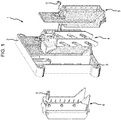
- the connection system essentially comprises: a plate 2 provided with louvers 3, here four in number, for fixing the connection system on a mounting support; a lock 4 movable transversely, that is to say in the plane of the plate 2, between a first retracted position, corresponding to an open position of the lock and a second advanced position corresponding to a closed position of the lock; a base 5 provided at one end of a first connector to be matched and which is fixed on the plate 2; and a plug 6 provided at one end of a second connector to be matched.
- the plate 2 comprises a set of openings 7, the number of which depends on the number of connectors to be connected. Although the number of openings is not limiting, in the various embodiments illustrated, the plate 2 can include one, three or five openings for the connection of one, three or five pairs of connectors.
- each opening the plate has a tab 8 for fixing by screwing the base 5 of the first connector.
- the peripheral edge of each opening 7 also comprises a set of reliefs delimiting an indentation serving to receive the base 5.
- the latter has essentially a U-shape and comprises two lateral branches 4a and 4b joined by a base 4c provided with a curved upper tab 4d intended to be operated manually.
- Each branch 4a and 4b of the lock comprises a set of slots, such as 4th, each delimiting a first ramp 4f and a second ramp 4g extending in parallel and serving respectively when connecting the connectors and the other when disconnecting.
- each of the 4th slots opens into a 4h end gadroon.
- the base 5 which is provided at one end of a first connector to be connected, constitutes a mounting part in which the first connector C1 is housed, or which is integral with the latter, and comprises, in this example, an end bracket 5a provided with a hole 5b for fixing the base by means of a screw V ( figure 1 ) on the plate 2.
- a screw V figure 1
- any other suitable means for fixing the base on the plate for example a clipping a weld, ...
- the plug 6 also constitutes an assembly part in which is housed the second connector C2 to be connected or which is integral with the latter.
- It essentially comprises a tail 6a which is intended to cause the movement of the lock at the start of the connection phase and a set of pins 6b the number of which corresponds to the slots 4e and which are intended to cooperate with the ramps 4f and 4g during the coupling, on the one hand and during uncoupling, on the other hand, of the connectors.
- the number and position of the pins and of the slots is chosen so as to allow a displacement of the plug in translation, in the axis of the contacts, during the displacement of the lock.
- the end zone of the tabs 4a and 4b comprises an inclined ramp, such as 4i, on which the end of the tail 6a rests.
- first connector and the base which it carries are fixed, by being screwed onto the plate 2, while the plug and the corresponding connector constitute a movable and removable part which is dissociated from the connection system until its connection.
- the lock 4 is inserted into the opening of the plate, and between the plate 3 and the base 5 so that the tab 4d is accessible from the side of the plate. plate 2 opposite the base 5.
- the plug 6 of the second connector which here constitutes a female connector, is approached to the plate 2, until the tail 6a bears against the end ramp 4i of the lock.
- the lock is moved sideways to a retracted position ( figures 6b and 6c ) allowing the complete insertion of the second connector to bring the first and second connectors into contact.
- This movement is advantageously carried out against a return force exerted by an elastically deformable element, such as a spring R interposed between the lock and the plate.
- the spring R is optional.
- the presence of one or more keying device (s) made in the form of a rod T which fits into a corresponding hole made in the plate, guarantees the insertion of the plug in line with the base when it is inserted into the plate.
- the lock is manually advanced by acting on the end shank 4d of the lock.
- This phase corresponds to the start of the assistance phase for connecting the connectors.
- the pins 6b come to rest against the ramp 4f of the slots 4e until they reach the end gadroon 4h ( figure 6f ), which corresponds to the end of the assistance phase.
- the correct connection of the connectors can be visually identified by virtue of a visual mark 10 provided on the plate and which is visible only when the lock is in the fully advanced position.
- connection system according to the invention is also suitable for providing assistance in uncoupling connectors. Disconnection is obtained by manually moving the lock to the advanced position.
- the lock should then be moved back ( figures 7b to 7e ) to cause the uncoupling of the contacts, thanks to the second ramp 4g on which the pins 6b rest. It will be noted that this movement takes place against the force exerted by the return spring R.
- the male contacts are completely extracted from the female contacts and the plug is in the retracted position.
- the plug is free and can be extracted manually.
Description
L'invention concerne, de manière générale, le raccordement électrique et la fixation mécanique de connecteurs.The invention relates, in general, to the electrical connection and the mechanical fixing of connectors.
De tels connecteurs peuvent être destinés à véhiculer des signaux d'alimentation ou de commande. Ils comportent par exemple un ensemble de modules de contacts, respectivement mâles et femelles, qui sont destinés à coopérer lors du raccordement.Such connectors can be intended to convey power or control signals. They comprise for example a set of contact modules, respectively male and female, which are intended to cooperate during connection.
L'assemblage des connecteurs nécessite des efforts d'assemblage qui peuvent être importants en fonction de la densité de points, c'est-à-dire de contacts, à connecter. Ces efforts sont liés à l'interpénétration des contacts entre eux. En effet, les contacts mâles doivent entrer en contact avec les contacts femelles, qui sont serrants, et qui opposent une résistance au montage. Lorsque les contacts sont hermaphrodites, le serrage est engendré de part et d'autre du connecteur et des efforts de montage peuvent également être importants.The assembly of the connectors requires assembly efforts which can be significant depending on the density of points, that is to say of contacts, to be connected. These efforts are linked to the interpenetration of contacts between them. Indeed, the male contacts must come into contact with the female contacts, which are tightening, and which oppose a resistance to the assembly. When the contacts are hermaphroditic, the tightening is generated on either side of the connector and mounting forces can also be significant.
En outre, les cadences de montage engendrent des problématiques de coût liées au temps d'installation et de maintenance des connecteurs. L'utilisation d'outils réduit cette cadence et monopolise en permanence une main d'un opérateur.In addition, the assembly rates generate cost issues related to the installation and maintenance time of the connectors. The use of tools reduces this rate and permanently monopolizes an operator's hand.
Enfin, il est nécessaire de pouvoir analyser rapidement le bon verrouillage des connecteurs, ce qui peut être incompatible avec les systèmes de raccordement conventionnels par vissage car les couples de serrage ne peuvent être appréciés visuellement, ou avec les systèmes de raccordement conventionnels par clipsage ou à quart de tour qui peuvent rester partiellement verrouillés sans qu'un examen visuel permette d'identifier le raccordement imparfait.Finally, it is necessary to be able to quickly analyze the correct locking of the connectors, which may be incompatible with conventional screw connection systems because the tightening torques cannot be assessed visually, or with conventional connection systems by clipping or quarter turn which can remain partially locked without visual inspection identifying the imperfect connection.
Le document
Le document
Toutefois, les dispositifs de ces documents sont relativement difficiles à mettre en œuvre, en particulier d'une seule main.However, the devices of these documents are relatively difficult to implement, in particular with one hand.
Au vu de ce qui précède, le but de l'invention est de proposer un système de raccordement de connecteurs ne nécessitant aucun outil pour l'accouplement et le désaccouplement du système, qui puisse être mis en œuvre de façon aisée, d'une seule main, et qui procure une assistance au montage et au démontage afin de réduire les efforts d'accouplement et de désaccouplement.In view of the foregoing, the aim of the invention is to provide a connector connection system requiring no tool for coupling and uncoupling of the system, which can be implemented easily, with a single hand, and which provides a assistance with assembly and disassembly in order to reduce coupling and uncoupling efforts.
L'invention a donc pour objet un système de raccordement d'au moins une paire de connecteurs appariés selon la revendication comprenant une platine comprenant une ouverture pour chaque paire de connecteurs et sur laquelle vient se fixer un premier connecteur de ladite paire et un verrou déplaçable latéralement par rapport à la platine et au premier connecteur, ledit verrou étant déplaçable dans une première position apte à permettre l'insertion du deuxième connecteur de ladite paire jusqu'à la mise en contact des connecteurs et dans une deuxième position stable d'accouplement et de verrouillage des connecteurs.The subject of the invention is therefore a system for connecting at least one pair of matched connectors according to claim comprising a plate comprising an opening for each pair of connectors and on which is fixed a first connector of said pair and a movable lock. laterally with respect to the plate and to the first connector, said lock being movable in a first position capable of allowing the insertion of the second connector of said pair until the connectors come into contact and in a second stable coupling position and locking connectors.
La première position correspond donc à une position ouverte du verrou, dans laquelle le verrou est par exemple dans une position reculée, tandis que la deuxième position correspond à une position fermée du verrou dans laquelle le verrou est par exemple en position avancée.The first position therefore corresponds to an open position of the lock, in which the lock is for example in a retracted position, while the second position corresponds to a closed position of the lock in which the lock is for example in the advanced position.
Selon une autre caractéristique du système de raccordement selon l'invention, le verrou comporte un ensemble d'au moins une première rampe sur laquelle s'appuie un pion prévu sur le deuxième connecteur lors du déplacement du verrou dans la deuxième position.According to another characteristic of the connection system according to the invention, the lock comprises an assembly of at least a first ramp on which rests a pin provided on the second connector when the lock is moved into the second position.
Le verrou comporte en outre un ensemble d'au moins une deuxième rampe parallèle à la première rampe et sur laquelle s'appuie le pion lors du déplacement du verrou dans la première position pour le désaccouplement des connecteurs.The lock further comprises a set of at least one second ramp parallel to the first ramp and on which the pin rests when moving the lock into the first position for uncoupling the connectors.
Dans un mode de réalisation, les rampes débouchent dans un godron de verrouillage.In one embodiment, the ramps open into a locking gadroon.
Selon encore une autre caractéristique, le premier et le deuxième connecteurs comportent respectivement une embase d'extrémité équipée de moyens de fixation sur la platine et une fiche sur laquelle sont prévus le ou les pions.According to yet another characteristic, the first and the second connectors respectively comprise an end base fitted with means for fixing to the plate and a plug on which the pin or pins are provided.
Le deuxième connecteur comporte une queue de commande du déplacement du verrou dans la première position reculée, pour s'appuyer contre une rampe d'extrémité du verrou quand la fiche du deuxième connecteur est approchée de la platine.The second connector has a tail for controlling the movement of the lock in the first retracted position, to rest against an end ramp of the lock when the plug of the second connector is approached to the plate.
On prévoira alors avantageusement un élément élastique de rappel sollicitant le verrou dans la première position.An elastic return element will then advantageously be provided urging the latch in the first position.
On prévoira en outre, avantageusement, un repère visuel placé sur le trajet du verrou et visible uniquement lorsque le verrou est en position de verrouillage.Advantageously, there will also be a visual marker placed on the path of the lock and visible only when the lock is in the locked position.
Dans un mode de réalisation, le système comporte une couche de matériau compressible adaptée pour être comprimée en fin de course d'accouplement des connecteurs ou en début de course de désaccouplement des connecteurs.In one embodiment, the system comprises a layer of compressible material suitable for being compressed at the end of the coupling travel of the connectors or at the start of the uncoupling travel of the connectors.
Dans un mode de réalisation, le système comporte une coiffe de protection contre des rayonnements électromagnétiques.In one embodiment, the system includes a cap for protection against electromagnetic radiation.
D'autres buts, caractéristiques et avantages de l'invention apparaîtront à la lecture de la description suivante, donnée uniquement à titre d'exemple non limitatif et faite en référence aux dessins annexés, sur lesquels :
- la
figure 1 est une vue éclatée en perspective d'un système de raccordement conforme à l'invention ; - les
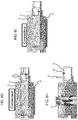
figures 2a, 2b et 2c montrent divers modes de réalisation de la platine du système de lafigure 1 ; - la
figure 3 montre le verrou du système de raccordement de lafigure 1 ; - les
figures 4 et 5 montrent respectivement l'embase et la fiche des premier et deuxième connecteurs ; - les
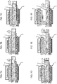
figures 6a à 6i illustrent la cinématique d'assemblage des connecteurs au moyen d'un système de raccordement selon l'invention ; et - les
figures 7a à 7f illustrent la cinématique de désaccouplement des connecteurs au moyen d'un système de raccordement selon l'invention.
- the
figure 1 is an exploded perspective view of a connection system according to the invention; - the
figures 2a, 2b and 2c show various embodiments of the system plate of thefigure 1 ; - the
figure 3 shows the lock of the connection system of thefigure 1 ; - the
figures 4 and 5 respectively show the base and the plug of the first and second connectors; - the
figures 6a to 6i illustrate the kinematics of assembly of the connectors by means of a connection system according to the invention; and - the
figures 7a to 7f illustrate the kinematics of uncoupling of the connectors by means of a connection system according to the invention.
On se référera tout d'abord aux
Dans l'application envisagée, nullement limitative, ce système de raccordement 1 est destiné à procurer une assistance au raccordement de deux connecteurs, respectivement mâle et femelle, pour une application avionique.In the envisaged application, which is in no way limiting, this connection system 1 is intended to provide assistance in the connection of two connectors, respectively male and female, for an avionics application.
Comme on le sait, les connecteurs comportent classiquement un ensemble de modules de contacts, ayant un ensemble de contacts, mâles ou femelles, prévus aux extrémités de conducteurs à raccorder.As is known, connectors conventionally comprise a set of contact modules, having a set of contacts, male or female, provided at the ends of conductors to be connected.
Comme on le voit sur la
Comme le montrent les
Pour chaque ouverture, la platine comporte une patte 8 pour la fixation par vissage de l'embase 5 du premier connecteur. Le bord périphérique de chaque ouverture 7 comporte par ailleurs un ensemble de reliefs délimitant une empreinte servant à recevoir l'embase 5.For each opening, the plate has a
En ce qui concerne le verrou 4, celui-ci a essentiellement une forme en U et comporte deux branches latérales 4a et 4b réunies par une base 4c pourvue d'une patte supérieure 4d recourbée destinée à être manœuvrée manuellement.As regards the
Chaque branche 4a et 4b du verrou comporte un ensemble de fentes, telles que 4e, délimitant chacune une première rampe 4f et une deuxième rampe 4g s'étendant parallèlement et servant respectivement lors du raccordement des connecteurs et l'autre lors du désaccouplement. Comme on le voit, chacune des fentes 4e débouche dans un godron d'extrémité 4h.Each
En se référant à la
Comme montré sur la
Il comporte essentiellement une queue 6a qui est destinée à provoquer le déplacement du verrou en début de phase de raccordement et un ensemble de pions 6b dont le nombre correspond aux fentes 4e et qui sont destinés à coopérer avec les rampes 4f et 4g lors de l'accouplement, d'une part et lors du désaccouplement, d'autre part, des connecteurs. Le nombre et la position des pions et des fentes est choisi de manière à permettre un déplacement de la fiche en translation, dans l'axe des contacts, lors du déplacement du verrou.It essentially comprises a
En revenant à la
On se référera maintenant aux
On notera que le premier connecteur et l'embase qu'il porte sont fixes, en étant vissés sur la platine 2, tandis que la fiche et le connecteur correspondant constituent une partie mobile et amovible qui est dissociée du système de raccordement jusqu'à sa connexion.It will be noted that the first connector and the base which it carries are fixed, by being screwed onto the
De même, avant la mise en œuvre de la procédure de raccordement des connecteurs, le verrou 4 est inséré dans l'ouverture de la platine, et entre la platine 3 et l'embase 5 de sorte que la patte 4d soit accessible du côté de la platine 2 opposé à l'embase 5.Similarly, before the implementation of the connector connection procedure, the
Lors d'une première phase, la fiche 6 du deuxième connecteur, qui constitue ici un connecteur femelle, est approchée de la platine 2, jusqu'à ce que la queue 6a soit en appui contre la rampe d'extrémité 4i du verrou. Lorsque la fiche 6 est davantage engagée dans la platine, le verrou est déplacé latéralement jusqu'à une position reculée (
Lors du déplacement de la fiche 6 par rapport au verrou, les pions 6b s'engagent dans les fentes 4e. On notera que la position visible sur la
Lors de l'étape suivante (
En se référant aux
Dans la position illustrée à la
On notera également que, dans cette position, le bon raccordement des connecteurs peut être visuellement identifié grâce à un repère visuel 10 prévu sur la platine et qui n'est visible que lorsque le verrou est en position entièrement avancée.It will also be noted that, in this position, the correct connection of the connectors can be visually identified by virtue of a
On se référera enfin aux
En se référant tout d'abord à la
Il convient alors de reculer le verrou (
En fin de course du verrou, les contacts mâles sont entièrement extraits des contacts femelles et la fiche est en position reculée. Lorsque le verrou est entièrement déplacé en position avancée, la fiche est libre et peut être extraite manuellement.At the end of the lock stroke, the male contacts are completely extracted from the female contacts and the plug is in the retracted position. When the lock is fully moved to the advanced position, the plug is free and can be extracted manually.
On notera par ailleurs que le système qui vient d'être décrit peut en outre être doté d'un capot ou d'une coiffe en matériau électriquement conducteur (non représenté) pour constituer un blindage électromagnétique.It will also be noted that the system which has just been described can also be provided with a cover or a cap made of electrically conductive material (not shown) to constitute an electromagnetic shielding.
Claims (7)
- Connection system for at least one pair of paired connectors, including a plate (2) including an opening (7) for each pair of connectors, to which is attached a first connector of said pair and a bolt (4) that can be moved laterally in relation to the plate and to the first connector, said bolt (4) being moveable to a first position that enables insertion of the second connector of said pair until contact is made between the connectors and to a second stable coupling and locking position of the connectors, the bolt including an assembly of at least one first ramp (4f) against which bears a pin (6b) provided on the second connector when the bolt is moved to the second position, the bolt including an assembly of at least one second ramp (4g) parallel to the first ramp and against which the pin bears when the bolt is moved to the first position to uncouple the connectors, characterized in that the second connector has a handle (6a) for controlling the movement of the bolt to the first position, to bear against an end ramp (4i) of the bolt (4) when the plug of the second connector moves towards the plate (2).
- System according to Claim 1, characterised in that the ramps open out into a locking indentation (4h).
- System according to Claim 1 or 2, characterised in that the first and second connectors have respectively an end base provided with attachment means to the plate and a plug (6) carrying the pin or pins.
- System according to any one of Claims 1 to 3, comprising an element for holding the bolt in the first position.
- System according to any one of Claims 1 to 4, characterised in that the plate includes a visual marker (10) placed on the path of the bolt that is visible only when the bolt is in the locked position.
- System according to any one of Claims 1 to 5, comprising a layer of compressible material (9) designed to be compressed at the end of the coupling path of the connectors or at the beginning of the uncoupling path of the connectors.
- System according to any one of Claims 1 to 6, comprising a protective cover against electromagnetic radiation.
Applications Claiming Priority (1)
| Application Number | Priority Date | Filing Date | Title |
|---|---|---|---|
| FR1551619A FR3033091B1 (en) | 2015-02-25 | 2015-02-25 | CONNECTOR CONNECTION SYSTEM |
Publications (2)
| Publication Number | Publication Date |
|---|---|
| EP3062401A1 EP3062401A1 (en) | 2016-08-31 |
| EP3062401B1 true EP3062401B1 (en) | 2020-10-14 |
Family
ID=53274575
Family Applications (1)
| Application Number | Title | Priority Date | Filing Date |
|---|---|---|---|
| EP16156150.1A Active EP3062401B1 (en) | 2015-02-25 | 2016-02-17 | Connection system for connector |
Country Status (3)
| Country | Link |
|---|---|
| US (1) | US9666984B2 (en) |
| EP (1) | EP3062401B1 (en) |
| FR (1) | FR3033091B1 (en) |
Families Citing this family (4)
| Publication number | Priority date | Publication date | Assignee | Title |
|---|---|---|---|---|
| DE102014106277B4 (en) * | 2014-05-06 | 2016-07-21 | Phoenix Contact Gmbh & Co. Kg | An electronics housing with a terminal block for an electronic device |
| AU360084S (en) * | 2014-11-05 | 2015-01-22 | Orica Int Pte Ltd | Connector |
| JP6607088B2 (en) * | 2016-03-04 | 2019-11-20 | 住友電装株式会社 | connector |
| US9843126B1 (en) * | 2017-02-21 | 2017-12-12 | Sumitomo Wiring Systems, Ltd. | Connector housing assemblies with access hood and push surface |
Family Cites Families (23)
| Publication number | Priority date | Publication date | Assignee | Title |
|---|---|---|---|---|
| FR2705503B1 (en) * | 1993-05-21 | 1995-07-28 | Francelco Sa | Electrical connector with insertion and extraction drawer. |
| WO1997008783A1 (en) * | 1995-08-22 | 1997-03-06 | The Whitaker Corporation | Arrangement with two half-plugs for securing in a wall |
| EP0942491A3 (en) * | 1998-03-13 | 2000-11-02 | The Whitaker Corporation | Sealed electrical connector with secondary locking member |
| DE19837896A1 (en) * | 1998-08-20 | 2000-02-24 | Delphi Automotive Systems Gmbh | Electrical connector |
| JP3412562B2 (en) * | 1999-06-14 | 2003-06-03 | 住友電装株式会社 | Lever connector |
| JP3675242B2 (en) * | 1999-08-04 | 2005-07-27 | 矢崎総業株式会社 | Low insertion force connector |
| ES1044100Y (en) * | 1999-08-06 | 2000-08-16 | Mecanismos Aux Ind | ANCHORAGE SYSTEM FOR CONNECTOR BOX IN SERVICE BOXES. |
| US6475004B2 (en) * | 2001-01-09 | 2002-11-05 | Tyco Electronics Corporation | Connector assembly with an engagement assist member and connector position assurance device |
| JP3887693B2 (en) * | 2001-11-12 | 2007-02-28 | 住友電装株式会社 | Lever type connector |
| JP3926223B2 (en) * | 2002-06-28 | 2007-06-06 | 株式会社オートネットワーク技術研究所 | Breaker device |
| US6824406B1 (en) * | 2003-06-26 | 2004-11-30 | Delphi Technologies, Inc. | Electrical connector assembly |
| FR2860650A1 (en) * | 2003-10-07 | 2005-04-08 | Framatome Connectors Int | ELECTRICAL CONNECTOR PROVIDED WITH A QUICK DISCONNECT SYSTEM |
| FR2864355A1 (en) * | 2003-12-19 | 2005-06-24 | Framatome Connectors Int | Connector case for motor vehicle, has clamp retaining electrical door-contact module in frame in locking position of module, and comprising rails that slide on shoulder of ribs, when module is in locking position |
| DE102004017275A1 (en) * | 2004-04-07 | 2005-10-27 | Tyco Electronics Amp Gmbh | Sealed plug-in connection through a partition and mounting method |
| US6979213B1 (en) * | 2004-10-20 | 2005-12-27 | Sews-Dtc, Inc. | Electrical junction box with sliding lock lever |
| JP4415267B2 (en) * | 2005-02-02 | 2010-02-17 | 住友電装株式会社 | Shield connector |
| JP4558583B2 (en) * | 2005-05-31 | 2010-10-06 | 矢崎総業株式会社 | Connector mating structure |
| JP4655960B2 (en) * | 2006-02-24 | 2011-03-23 | 住友電装株式会社 | connector |
| US7347704B2 (en) * | 2006-03-01 | 2008-03-25 | Sumitomo Wiring Systems, Ltd. | Connector |
| US7303415B2 (en) * | 2006-03-31 | 2007-12-04 | Fci Americas Technology, Inc. | Electrical connector with mate-assist and a dual-position wire dress cover |
| US7329132B1 (en) * | 2006-07-31 | 2008-02-12 | Yazaki North America, Inc. | Low-insertion force-lever connector for blind mating |
| JP4130467B1 (en) * | 2007-03-07 | 2008-08-06 | タイコエレクトロニクスアンプ株式会社 | Lever type connector |
| JP2014017135A (en) * | 2012-07-10 | 2014-01-30 | Tyco Electronics Japan Kk | Connector |
-
2015
- 2015-02-25 FR FR1551619A patent/FR3033091B1/en active Active
-
2016
- 2016-02-17 EP EP16156150.1A patent/EP3062401B1/en active Active
- 2016-02-24 US US15/052,692 patent/US9666984B2/en active Active
Non-Patent Citations (1)
| Title |
|---|
| None * |
Also Published As
| Publication number | Publication date |
|---|---|
| FR3033091B1 (en) | 2018-05-25 |
| EP3062401A1 (en) | 2016-08-31 |
| US20160248201A1 (en) | 2016-08-25 |
| US9666984B2 (en) | 2017-05-30 |
| FR3033091A1 (en) | 2016-08-26 |
Similar Documents
| Publication | Publication Date | Title |
|---|---|---|
| EP3062401B1 (en) | Connection system for connector | |
| EP1729376B1 (en) | Locking lever mechanism for connector | |
| EP0633633B1 (en) | Card connector, especially for an electronic card | |
| FR2824960A1 (en) | PUSH-BUTTON CONNECTION DEVICE | |
| EP3103164B1 (en) | Connector and corresponding connector assembly | |
| FR3051079A1 (en) | LOCKING DEVICE FOR ELECTRICAL CONNECTORS AND ELECTRICAL CONNECTORS EQUIPPED WITH THE DEVICE. | |
| EP2061118A1 (en) | Easy-mounting connector for multicore cable | |
| FR3073681A1 (en) | DEVICE FOR CONNECTING AND DISCONNECTING AN ELECTRIC CABLE | |
| EP3487006B1 (en) | Electrical system comprising an electrical apparatus and an interchangeable connector module | |
| EP1865578B1 (en) | Self-stripping terminal for an insulated electrical conductor and electrical equipment comprising such a terminal | |
| EP1958296B1 (en) | Electric connector | |
| EP1286427A1 (en) | Terminal-block with lock-arm for plug connector | |
| EP1276175B1 (en) | Hybrid connector | |
| FR2688350A1 (en) | Electrical connection device and, more particularly, a charging (load) connector | |
| EP2257145B1 (en) | Connection device | |
| FR2777392A1 (en) | Lockable electrical connector | |
| FR3028356A1 (en) | ELECTRICAL CONNECTION TERMINAL WITH IMPERDABLE SCREW | |
| FR2631749A1 (en) | Lockable module for a connector | |
| FR2813997A1 (en) | Connector for conductor wire to printed circuit has blade with flanges to retain wire and spaced contacts to fit into hole in circuit board | |
| EP1496575B1 (en) | Contact | |
| EP2518833B1 (en) | Spring-mounted connection terminal | |
| FR2655207A1 (en) | Electrical connector which includes improved terminal retention means | |
| FR3078590A1 (en) | CONNECTOR WITH CONNECTION ASSIST LEVER LATCH | |
| FR2698732A1 (en) | Releasable connector for missiles or rockets - has cable pulling section with enlarged hole pushing connector up and shearing shear pins | |
| FR2915026A1 (en) | Tuning fork shaped flat cable connecting device for road vehicle, has closing elements allowing perforation of cable by spigots to establish electrical connection between conductors of cables and maintain cable clamped against base wall |
Legal Events
| Date | Code | Title | Description |
|---|---|---|---|
| PUAI | Public reference made under article 153(3) epc to a published international application that has entered the european phase |
Free format text: ORIGINAL CODE: 0009012 |
|
| AK | Designated contracting states |
Kind code of ref document: A1 Designated state(s): AL AT BE BG CH CY CZ DE DK EE ES FI FR GB GR HR HU IE IS IT LI LT LU LV MC MK MT NL NO PL PT RO RS SE SI SK SM TR |
|
| AX | Request for extension of the european patent |
Extension state: BA ME |
|
| 17P | Request for examination filed |
Effective date: 20161025 |
|
| STAA | Information on the status of an ep patent application or granted ep patent |
Free format text: STATUS: EXAMINATION IS IN PROGRESS |
|
| 17Q | First examination report despatched |
Effective date: 20180122 |
|
| GRAP | Despatch of communication of intention to grant a patent |
Free format text: ORIGINAL CODE: EPIDOSNIGR1 |
|
| STAA | Information on the status of an ep patent application or granted ep patent |
Free format text: STATUS: GRANT OF PATENT IS INTENDED |
|
| INTG | Intention to grant announced |
Effective date: 20200518 |
|
| GRAS | Grant fee paid |
Free format text: ORIGINAL CODE: EPIDOSNIGR3 |
|
| GRAA | (expected) grant |
Free format text: ORIGINAL CODE: 0009210 |
|
| STAA | Information on the status of an ep patent application or granted ep patent |
Free format text: STATUS: THE PATENT HAS BEEN GRANTED |
|
| AK | Designated contracting states |
Kind code of ref document: B1 Designated state(s): AL AT BE BG CH CY CZ DE DK EE ES FI FR GB GR HR HU IE IS IT LI LT LU LV MC MK MT NL NO PL PT RO RS SE SI SK SM TR |
|
| REG | Reference to a national code |
Ref country code: GB Ref legal event code: FG4D Free format text: NOT ENGLISH |
|
| REG | Reference to a national code |
Ref country code: AT Ref legal event code: REF Ref document number: 1324498 Country of ref document: AT Kind code of ref document: T Effective date: 20201015 Ref country code: CH Ref legal event code: EP |
|
| REG | Reference to a national code |
Ref country code: DE Ref legal event code: R096 Ref document number: 602016045687 Country of ref document: DE |
|
| REG | Reference to a national code |
Ref country code: IE Ref legal event code: FG4D Free format text: LANGUAGE OF EP DOCUMENT: FRENCH |
|
| REG | Reference to a national code |
Ref country code: AT Ref legal event code: MK05 Ref document number: 1324498 Country of ref document: AT Kind code of ref document: T Effective date: 20201014 |
|
| REG | Reference to a national code |
Ref country code: NL Ref legal event code: MP Effective date: 20201014 |
|
| PG25 | Lapsed in a contracting state [announced via postgrant information from national office to epo] |
Ref country code: FI Free format text: LAPSE BECAUSE OF FAILURE TO SUBMIT A TRANSLATION OF THE DESCRIPTION OR TO PAY THE FEE WITHIN THE PRESCRIBED TIME-LIMIT Effective date: 20201014 Ref country code: PT Free format text: LAPSE BECAUSE OF FAILURE TO SUBMIT A TRANSLATION OF THE DESCRIPTION OR TO PAY THE FEE WITHIN THE PRESCRIBED TIME-LIMIT Effective date: 20210215 Ref country code: RS Free format text: LAPSE BECAUSE OF FAILURE TO SUBMIT A TRANSLATION OF THE DESCRIPTION OR TO PAY THE FEE WITHIN THE PRESCRIBED TIME-LIMIT Effective date: 20201014 Ref country code: NO Free format text: LAPSE BECAUSE OF FAILURE TO SUBMIT A TRANSLATION OF THE DESCRIPTION OR TO PAY THE FEE WITHIN THE PRESCRIBED TIME-LIMIT Effective date: 20210114 Ref country code: NL Free format text: LAPSE BECAUSE OF FAILURE TO SUBMIT A TRANSLATION OF THE DESCRIPTION OR TO PAY THE FEE WITHIN THE PRESCRIBED TIME-LIMIT Effective date: 20201014 Ref country code: GR Free format text: LAPSE BECAUSE OF FAILURE TO SUBMIT A TRANSLATION OF THE DESCRIPTION OR TO PAY THE FEE WITHIN THE PRESCRIBED TIME-LIMIT Effective date: 20210115 |
|
| REG | Reference to a national code |
Ref country code: LT Ref legal event code: MG4D |
|
| PG25 | Lapsed in a contracting state [announced via postgrant information from national office to epo] |
Ref country code: ES Free format text: LAPSE BECAUSE OF FAILURE TO SUBMIT A TRANSLATION OF THE DESCRIPTION OR TO PAY THE FEE WITHIN THE PRESCRIBED TIME-LIMIT Effective date: 20201014 Ref country code: AT Free format text: LAPSE BECAUSE OF FAILURE TO SUBMIT A TRANSLATION OF THE DESCRIPTION OR TO PAY THE FEE WITHIN THE PRESCRIBED TIME-LIMIT Effective date: 20201014 Ref country code: BG Free format text: LAPSE BECAUSE OF FAILURE TO SUBMIT A TRANSLATION OF THE DESCRIPTION OR TO PAY THE FEE WITHIN THE PRESCRIBED TIME-LIMIT Effective date: 20210114 Ref country code: LV Free format text: LAPSE BECAUSE OF FAILURE TO SUBMIT A TRANSLATION OF THE DESCRIPTION OR TO PAY THE FEE WITHIN THE PRESCRIBED TIME-LIMIT Effective date: 20201014 Ref country code: SE Free format text: LAPSE BECAUSE OF FAILURE TO SUBMIT A TRANSLATION OF THE DESCRIPTION OR TO PAY THE FEE WITHIN THE PRESCRIBED TIME-LIMIT Effective date: 20201014 Ref country code: IS Free format text: LAPSE BECAUSE OF FAILURE TO SUBMIT A TRANSLATION OF THE DESCRIPTION OR TO PAY THE FEE WITHIN THE PRESCRIBED TIME-LIMIT Effective date: 20210214 Ref country code: PL Free format text: LAPSE BECAUSE OF FAILURE TO SUBMIT A TRANSLATION OF THE DESCRIPTION OR TO PAY THE FEE WITHIN THE PRESCRIBED TIME-LIMIT Effective date: 20201014 |
|
| PG25 | Lapsed in a contracting state [announced via postgrant information from national office to epo] |
Ref country code: HR Free format text: LAPSE BECAUSE OF FAILURE TO SUBMIT A TRANSLATION OF THE DESCRIPTION OR TO PAY THE FEE WITHIN THE PRESCRIBED TIME-LIMIT Effective date: 20201014 |
|
| REG | Reference to a national code |
Ref country code: DE Ref legal event code: R097 Ref document number: 602016045687 Country of ref document: DE |
|
| PG25 | Lapsed in a contracting state [announced via postgrant information from national office to epo] |
Ref country code: SK Free format text: LAPSE BECAUSE OF FAILURE TO SUBMIT A TRANSLATION OF THE DESCRIPTION OR TO PAY THE FEE WITHIN THE PRESCRIBED TIME-LIMIT Effective date: 20201014 Ref country code: RO Free format text: LAPSE BECAUSE OF FAILURE TO SUBMIT A TRANSLATION OF THE DESCRIPTION OR TO PAY THE FEE WITHIN THE PRESCRIBED TIME-LIMIT Effective date: 20201014 Ref country code: EE Free format text: LAPSE BECAUSE OF FAILURE TO SUBMIT A TRANSLATION OF THE DESCRIPTION OR TO PAY THE FEE WITHIN THE PRESCRIBED TIME-LIMIT Effective date: 20201014 Ref country code: CZ Free format text: LAPSE BECAUSE OF FAILURE TO SUBMIT A TRANSLATION OF THE DESCRIPTION OR TO PAY THE FEE WITHIN THE PRESCRIBED TIME-LIMIT Effective date: 20201014 Ref country code: SM Free format text: LAPSE BECAUSE OF FAILURE TO SUBMIT A TRANSLATION OF THE DESCRIPTION OR TO PAY THE FEE WITHIN THE PRESCRIBED TIME-LIMIT Effective date: 20201014 Ref country code: LT Free format text: LAPSE BECAUSE OF FAILURE TO SUBMIT A TRANSLATION OF THE DESCRIPTION OR TO PAY THE FEE WITHIN THE PRESCRIBED TIME-LIMIT Effective date: 20201014 |
|
| PLBE | No opposition filed within time limit |
Free format text: ORIGINAL CODE: 0009261 |
|
| STAA | Information on the status of an ep patent application or granted ep patent |
Free format text: STATUS: NO OPPOSITION FILED WITHIN TIME LIMIT |
|
| PG25 | Lapsed in a contracting state [announced via postgrant information from national office to epo] |
Ref country code: DK Free format text: LAPSE BECAUSE OF FAILURE TO SUBMIT A TRANSLATION OF THE DESCRIPTION OR TO PAY THE FEE WITHIN THE PRESCRIBED TIME-LIMIT Effective date: 20201014 |
|
| 26N | No opposition filed |
Effective date: 20210715 |
|
| PG25 | Lapsed in a contracting state [announced via postgrant information from national office to epo] |
Ref country code: MC Free format text: LAPSE BECAUSE OF FAILURE TO SUBMIT A TRANSLATION OF THE DESCRIPTION OR TO PAY THE FEE WITHIN THE PRESCRIBED TIME-LIMIT Effective date: 20201014 |
|
| REG | Reference to a national code |
Ref country code: BE Ref legal event code: MM Effective date: 20210228 |
|
| PG25 | Lapsed in a contracting state [announced via postgrant information from national office to epo] |
Ref country code: AL Free format text: LAPSE BECAUSE OF FAILURE TO SUBMIT A TRANSLATION OF THE DESCRIPTION OR TO PAY THE FEE WITHIN THE PRESCRIBED TIME-LIMIT Effective date: 20201014 Ref country code: CH Free format text: LAPSE BECAUSE OF NON-PAYMENT OF DUE FEES Effective date: 20210228 Ref country code: IT Free format text: LAPSE BECAUSE OF FAILURE TO SUBMIT A TRANSLATION OF THE DESCRIPTION OR TO PAY THE FEE WITHIN THE PRESCRIBED TIME-LIMIT Effective date: 20201014 Ref country code: LI Free format text: LAPSE BECAUSE OF NON-PAYMENT OF DUE FEES Effective date: 20210228 Ref country code: LU Free format text: LAPSE BECAUSE OF NON-PAYMENT OF DUE FEES Effective date: 20210217 |
|
| PG25 | Lapsed in a contracting state [announced via postgrant information from national office to epo] |
Ref country code: SI Free format text: LAPSE BECAUSE OF FAILURE TO SUBMIT A TRANSLATION OF THE DESCRIPTION OR TO PAY THE FEE WITHIN THE PRESCRIBED TIME-LIMIT Effective date: 20201014 |
|
| PG25 | Lapsed in a contracting state [announced via postgrant information from national office to epo] |
Ref country code: IE Free format text: LAPSE BECAUSE OF NON-PAYMENT OF DUE FEES Effective date: 20210217 |
|
| PG25 | Lapsed in a contracting state [announced via postgrant information from national office to epo] |
Ref country code: IS Free format text: LAPSE BECAUSE OF FAILURE TO SUBMIT A TRANSLATION OF THE DESCRIPTION OR TO PAY THE FEE WITHIN THE PRESCRIBED TIME-LIMIT Effective date: 20210214 |
|
| PG25 | Lapsed in a contracting state [announced via postgrant information from national office to epo] |
Ref country code: BE Free format text: LAPSE BECAUSE OF NON-PAYMENT OF DUE FEES Effective date: 20210228 |
|
| PGFP | Annual fee paid to national office [announced via postgrant information from national office to epo] |
Ref country code: FR Payment date: 20230131 Year of fee payment: 8 |
|
| PG25 | Lapsed in a contracting state [announced via postgrant information from national office to epo] |
Ref country code: HU Free format text: LAPSE BECAUSE OF FAILURE TO SUBMIT A TRANSLATION OF THE DESCRIPTION OR TO PAY THE FEE WITHIN THE PRESCRIBED TIME-LIMIT; INVALID AB INITIO Effective date: 20160217 |
|
| PGFP | Annual fee paid to national office [announced via postgrant information from national office to epo] |
Ref country code: GB Payment date: 20230222 Year of fee payment: 8 Ref country code: DE Payment date: 20230207 Year of fee payment: 8 |
|
| PG25 | Lapsed in a contracting state [announced via postgrant information from national office to epo] |
Ref country code: CY Free format text: LAPSE BECAUSE OF FAILURE TO SUBMIT A TRANSLATION OF THE DESCRIPTION OR TO PAY THE FEE WITHIN THE PRESCRIBED TIME-LIMIT Effective date: 20201014 |