JP4655960B2 - connector - Google Patents
connector Download PDFInfo
- Publication number
- JP4655960B2 JP4655960B2 JP2006048672A JP2006048672A JP4655960B2 JP 4655960 B2 JP4655960 B2 JP 4655960B2 JP 2006048672 A JP2006048672 A JP 2006048672A JP 2006048672 A JP2006048672 A JP 2006048672A JP 4655960 B2 JP4655960 B2 JP 4655960B2
- Authority
- JP
- Japan
- Prior art keywords
- detection
- slider
- housing
- detection member
- fitting
- Prior art date
- Legal status (The legal status is an assumption and is not a legal conclusion. Google has not performed a legal analysis and makes no representation as to the accuracy of the status listed.)
- Expired - Fee Related
Links
Images


Classifications
-
- H—ELECTRICITY
- H01—ELECTRIC ELEMENTS
- H01R—ELECTRICALLY-CONDUCTIVE CONNECTIONS; STRUCTURAL ASSOCIATIONS OF A PLURALITY OF MUTUALLY-INSULATED ELECTRICAL CONNECTING ELEMENTS; COUPLING DEVICES; CURRENT COLLECTORS
- H01R13/00—Details of coupling devices of the kinds covered by groups H01R12/70 or H01R24/00 - H01R33/00
- H01R13/62—Means for facilitating engagement or disengagement of coupling parts or for holding them in engagement
- H01R13/629—Additional means for facilitating engagement or disengagement of coupling parts, e.g. aligning or guiding means, levers, gas pressure electrical locking indicators, manufacturing tolerances
- H01R13/62905—Additional means for facilitating engagement or disengagement of coupling parts, e.g. aligning or guiding means, levers, gas pressure electrical locking indicators, manufacturing tolerances comprising a camming member
- H01R13/62927—Comprising supplementary or additional locking means
-
- H—ELECTRICITY
- H01—ELECTRIC ELEMENTS
- H01R—ELECTRICALLY-CONDUCTIVE CONNECTIONS; STRUCTURAL ASSOCIATIONS OF A PLURALITY OF MUTUALLY-INSULATED ELECTRICAL CONNECTING ELEMENTS; COUPLING DEVICES; CURRENT COLLECTORS
- H01R13/00—Details of coupling devices of the kinds covered by groups H01R12/70 or H01R24/00 - H01R33/00
- H01R13/62—Means for facilitating engagement or disengagement of coupling parts or for holding them in engagement
- H01R13/629—Additional means for facilitating engagement or disengagement of coupling parts, e.g. aligning or guiding means, levers, gas pressure electrical locking indicators, manufacturing tolerances
- H01R13/62933—Comprising exclusively pivoting lever
- H01R13/6295—Pivoting lever comprising means indicating incorrect coupling of mating connectors
-
- H—ELECTRICITY
- H01—ELECTRIC ELEMENTS
- H01R—ELECTRICALLY-CONDUCTIVE CONNECTIONS; STRUCTURAL ASSOCIATIONS OF A PLURALITY OF MUTUALLY-INSULATED ELECTRICAL CONNECTING ELEMENTS; COUPLING DEVICES; CURRENT COLLECTORS
- H01R13/00—Details of coupling devices of the kinds covered by groups H01R12/70 or H01R24/00 - H01R33/00
- H01R13/64—Means for preventing incorrect coupling
- H01R13/641—Means for preventing incorrect coupling by indicating incorrect coupling; by indicating correct or full engagement
Landscapes
- Details Of Connecting Devices For Male And Female Coupling (AREA)
Description
本発明は、コネクタに関する。 The present invention relates to a connector.
従来、スライド式のレバー(以下、スライダという。)による倍力機構を用いたコネクタの一般的構造としては、下記特許文献1に記載のものが知られている。このものは、スライダをスライド操作することにより両ハウジングが嵌合完了状態となった後、スライダの移動方向と直交する方向に沿ってストレートに移動可能な検知部材を備えている。
しかしながら、このものは、検知部材がストレートに移動可能であるため、両ハウジングの設置状況によっては、検知部材が検知位置に至ったか否かを外観判断する作業者の視線が検知部材の移動方向背面側に存在し、検知部材の移動の前後で検知操作が確認しずらいという問題がある。本発明は上記のような事情に基づいて完成されたものであって、検知部材の検知操作を確認しやすくすることを目的とする。 However, in this case, since the detection member can move straight, depending on the installation status of both housings, the operator's line of sight to determine whether or not the detection member has reached the detection position is behind the detection member in the movement direction. There is a problem that it is difficult to confirm the detection operation before and after the movement of the detection member. This invention is completed based on the above situations, Comprising: It aims at making it easy to confirm detection operation of a detection member.
上記の目的を達成するための手段として、請求項1の発明は、第1ハウジングと、この第1ハウジングと嵌合可能で、かつフォロアピンを有する第2ハウジングと、前記第1ハウジングに対して両ハウジングの嵌合方向と直交する方向からスライド操作可能に組み付けられ、かつ前記フォロアピンと係合可能なカム溝を有し、かつ前記スライド操作により前記フォロアピンと前記カム溝との係合によるカム作用によって前記両ハウジングの嵌合を行わせて嵌合完了状態に至らしめるスライダと、前記第1ハウジングに組み付けられ、かつ前記スライダの操作途上では検知位置への移動が規制されるとともに前記スライダの操作完了位置では検知位置への移動が許容される検知部材とを備えるコネクタであって、前記第1ハウジングの外面には、前記検知位置にある前記検知部材が嵌り込む収容部が設けられ、前記検知位置では前記検知部材が前記収容部の外部にはみ出さないようにされており、前記検知部材は前記第1ハウジングの外面に露出した状態で前記第1ハウジングに対して回動可能に組み付けられている構成としたところに特徴を有する。 As means for achieving the above-mentioned object, the invention of claim 1 is directed to a first housing, a second housing that can be fitted to the first housing and has a follower pin, and the first housing. The cam groove is assembled so as to be slidable from a direction orthogonal to the fitting direction of the housing and can be engaged with the follower pin, and by the cam action by the engagement of the follower pin and the cam groove by the sliding operation. A slider that allows the two housings to be fitted to each other and a fitting completion state, and a slider that is assembled to the first housing and that moves to the detection position during the operation of the slider is restricted and the operation of the slider is completed. in the position a connector and a detecting member is moved to the detection position is permitted, on the outer surface of the first housing Wherein said detecting member in the detection position is provided accommodating portion fits, the at detection position is to the detection member does not protrude to the outside of the accommodating portion, the sensing member is an outer surface of the first housing It is characterized in that it is configured so as to be rotatable with respect to the first housing in a state where the first housing is exposed.
請求項2の発明は、請求項1に記載のものにおいて、前記検知部材は、前記第1ハウジング内の前記スライダの進入路に臨む位置に組み付けられ、前記検知部材もしくは前記スライダのうちいずれか一方には、検知リブが設けられることで、前記スライダの操作途上では前記検知リブが他方に摺接して前記検知部材を前記進入路側に押し込めないものの、前記他方には、前記検知リブが整合して収容される検知孔が設けられることで、前記スライダが前記操作完了位置に至ったときに初めて前記検知部材を前記検知位置に至るまで押し込めるところに特徴を有する。 According to a second aspect of the present invention, in the first aspect, the detection member is assembled at a position facing the entry path of the slider in the first housing, and either the detection member or the slider. Since the detection rib is provided, the detection rib is in sliding contact with the other during the operation of the slider and the detection member cannot be pushed into the approach path side, but the detection rib is aligned with the other. Since the detection hole to be accommodated is provided, the detection member can be pushed into the detection position for the first time when the slider reaches the operation completion position.
請求項3の発明は、請求項2に記載のものにおいて、前記検知リブには、前記スライダが半挿入状態にあるときに前記検知孔の孔縁部と摺接することで前記スライダを前記操作完了位置へ押し込む方向に作用する分力を生じさせる半挿入矯正面が設けられるところに特徴を有する。 According to a third aspect of the present invention, the operation of the slider according to the second aspect is completed when the slider is in sliding contact with a hole edge of the detection hole when the slider is in a half-inserted state. It is characterized in that a semi-insertion correction surface is provided that generates a component force acting in the direction of pushing into position.
請求項4の発明は、請求項2または請求項3に記載のものにおいて、前記カム溝は、前記両ハウジングを嵌合完了状態に至らしめるための作動領域と、この作動領域の奥側に連続し、かつ嵌合完了後のスライド操作によっても嵌合を進行させない遊び領域とからなり、前記フォロアピンが前記遊び領域を通過する間に、前記検知リブが前記検知孔に押し込まれるところに特徴を有する。 A fourth aspect of the present invention, continuous in what according to claim 2 or claim 3, wherein the cam groove, the a working area for allowed to reach completely connected state of both housings, the inner side of this operating region And a play area in which the fitting does not proceed even by a slide operation after the fitting is completed, and the detection rib is pushed into the detection hole while the follower pin passes through the play area. .
請求項5の発明は、請求項2ないし請求項4のいずれかに記載のものにおいて、前記スライダの進入路は、前記第1ハウジングを幅方向に貫通して設けて、その幅方向両側から選択的に組み付け可能とされ、前記第1ハウジングには、前記スライダの組み付け方向に応じて組み付け位置を選択可能とする回動支持部が対称位置に配されているところに特徴を有する。 According to a fifth aspect of the present invention, in the slider according to any one of the second to fourth aspects, the entry path of the slider is provided through the first housing in the width direction and is selected from both sides in the width direction. The first housing is characterized in that a rotation support portion is provided at a symmetrical position so that the assembly position can be selected in accordance with the assembly direction of the slider.
請求項6の発明は、請求項5に記載のものにおいて、前記回動支持部は共用され、前記スライダは、同スライダの組み付け方向に応じて付け替えができるようになっているところに特徴を有する。
The invention of
請求項7の発明は、請求項1ないし請求項6のいずれかに記載のものにおいて、前記検知部材は、前記検知位置に至ると前記第1ハウジングと係止して戻り方向への回動をロックする回動規制手段を設けたところに特徴と有する。 According to a seventh aspect of the present invention, in the apparatus according to any one of the first to sixth aspects, when the detection member reaches the detection position, the detection member engages with the first housing and rotates in the return direction. It is characterized in that a rotation restricting means for locking is provided.
請求項8の発明は、請求項7に記載のものにおいて、前記回動規制手段は、前記検知部材もしくは前記第1ハウジングのうちいずれか一方に撓み可能に設けられたロック部と、他方に配され、前記ロック部が乗り越えて復帰することにより係止するロック受け部とから構成されるところに特徴と有する。 According to an eighth aspect of the present invention, in the seventh aspect of the present invention, the rotation restricting means includes a lock portion that is provided so as to be able to bend in either the detection member or the first housing, and the other. The lock portion is characterized in that it is constituted by a lock receiving portion that is locked by overcoming and returning.
<請求項1の発明>
請求項1の発明によれば、第1・第2のハウジングを浅く嵌合させた状態で、スライダをスライド操作する。これに伴い、フォロアピンがカム溝に沿って誘導されることで、両ハウジングが正規の嵌合状態に至る。その後、検知部材を初期の位置から回動操作し、検知位置に至ったことが確認されればスライダが正規位置までスライド操作されたこと、つまりは両ハウジングが正規の嵌合状態になっていることが確認される。
<Invention of Claim 1>
According to the invention of claim 1, the slider is slid in a state where the first and second housings are shallowly fitted. Along with this, the follower pins are guided along the cam grooves, so that both housings are brought into a normal fitting state. Thereafter, the detection member is rotated from the initial position, and if it is confirmed that the detection position has been reached, the slider has been slid to the normal position, that is, both housings are in the normal fitted state. That is confirmed.
しかし、仮にスライダのスライド操作が不完全であれば、検知部材は回動操作しても第1ハウジングと干渉するため、検知位置に至らしめることができない。
これをもって作業者は両ハウジングが正規の嵌合状態にないことを知ることができる。
However, if the sliding operation of the slider is incomplete, the detection member can interfere with the first housing even if it is rotated, and cannot reach the detection position.
With this, the operator can know that both housings are not in a proper fitting state.
ところで、請求項1の発明では、検知部材の変位形態が通常の平行移動でなく、回動の形態を採用している。平行移動の場合には、検知部材が検知位置に至ったか否かを外観判断する作業者の視線が検知部材の移動方向背面側に存在する場合には、検知部材の特定部位を第1ハウジング側に投影しても、検知部材が初期位置にあるときも検知位置にあるときも投影位置のずれがないため、作業者は検知位置と初期位置の差を認識できない。しかし、請求項1の発明のように、回動形態を採用すれば、仮に視線が上記のような位置にあったとしても、初期位置と検知位置との間では投影位置にずれを生じさせることができるため、検知部材が検知位置に至ったか否かを明確に認識することができる。 By the way, in invention of Claim 1, the displacement form of a detection member is employ | adopting the form of rotation instead of normal parallel movement. In the case of parallel movement, when the line of sight of an operator who determines whether or not the detection member has reached the detection position is present on the back side in the movement direction of the detection member, the specific part of the detection member is set on the first housing side. Even when the projection is performed, the operator cannot recognize the difference between the detection position and the initial position because there is no deviation of the projection position when the detection member is at the initial position or the detection position. However, as in the first aspect of the invention, if the rotation form is adopted, even if the line of sight is at the position as described above, a deviation occurs in the projection position between the initial position and the detection position. Therefore, it can be clearly recognized whether or not the detection member has reached the detection position.
<請求項2の発明>
請求項2の発明によると、検知部材は、スライダの操作途上では検知リブがスライダに摺接して進入路側に押し込めないものの、スライダが操作完了位置に至ったときに初めて検知位置に至るまで押し込めるから、検知部材が検知位置に至ったことを確実に検知することができる。
<Invention of
According to the second aspect of the present invention, the detection member is pushed in until the detection position is reached only when the slider reaches the operation completion position, although the detection rib is in sliding contact with the slider and cannot be pushed into the approach path side during the operation of the slider. It is possible to reliably detect that the detection member has reached the detection position.
<請求項3の発明>
請求項3の発明によると、検知リブには、半挿入矯正面が設けられるから、検知部材を押し込むことでスライダの半挿入状態を矯正して操作完了位置へ押し込むことができるとともに、操作完了位置にあるスライダを抜け方向に引き抜くことで検知リブを検知孔から自動的に押し出すことができるから、別途検知部材を押し上げる操作が不要となり、作業効率を向上させることができる。
<Invention of Claim 3>
According to the invention of claim 3, since the detection rib is provided with the half-insertion correction surface, the detection member can be pushed to correct the half-insertion state of the slider and pushed into the operation completion position. Since the detection rib can be automatically pushed out from the detection hole by pulling out the slider in the removal direction, there is no need to separately push up the detection member, and work efficiency can be improved.
<請求項4の発明>
請求項4の発明によると、カム溝は、両ハウジングを嵌合完了状態に至らしめるための作動領域と、この作動領域の奥側に連続し、かつ嵌合完了後のスライド操作によっても嵌合を進行させない遊び領域とからなるから、フォロアピンが遊び領域にある間に検知部材が検知孔に収容されることをもって、両ハウジングの嵌合完了状態を保証することができる。
<Invention of Claim 4>
According to the invention of claim 4, the cam groove is engaged by an operation region for bringing the two housings into the completion state of engagement and a back side of the operation region, and also by a slide operation after completion of the engagement. Therefore, when the detection member is accommodated in the detection hole while the follower pin is in the play area, the fitting completion state of both housings can be guaranteed.
<請求項5の発明>
請求項5の発明によると、スライダの進入路は、第1ハウジングを幅方向に貫通して設けて、その幅方向両側から選択的に組み付け可能とされ、第1ハウジングには、スライダの組み付け方向に応じて組み付け位置を選択可能とする回動支持部が対称位置に配されているから、両ハウジングの組み付け現場の状況に応じて、スライダの組み付け方向を自由に選択することができる。
<Invention of
According to the fifth aspect of the present invention, the entrance path of the slider is provided so as to penetrate the first housing in the width direction, and can be selectively assembled from both sides in the width direction. Since the rotation support portion that allows the assembly position to be selected according to the above is arranged at the symmetrical position, the assembly direction of the slider can be freely selected according to the situation at the assembly site of both housings.
<請求項6の発明>
請求項6の発明によると、回動支持部は共用され、スライダの組み付け方向に応じて付け替えができるようになっているから、回動支持部を個別に2箇所設ける必要がなく、構造を簡素化し、省スペース化することができる。
<Invention of
According to the invention of
<請求項7の発明>
請求項7の発明によると、検知部材は、検知位置に至ると第1ハウジングと係止して戻り方向への回動をロックする回動規制手段を設けたから、検知位置にある検知部材が不用意に回動してしまうことが規制される。
<Invention of Claim 7>
According to the seventh aspect of the invention, since the detection member is provided with the rotation restricting means that locks the rotation in the return direction by locking with the first housing when the detection member reaches the detection position, the detection member at the detection position is not suitable. It is restricted that it rotates in preparation.
<請求項8の発明>
請求項8の発明によると、回動規制手段は、検知部材もしくは第1ハウジングのうちいずれか一方に撓み可能に設けられたロック部と、他方に配され、ロック部が乗り越えて復帰することにより係止するロック受け部とから構成されるから、ロック部とロック受け部が係止し合う際の節度感によっても検知操作の確認が可能である。
<Invention of Claim 8>
According to the invention of claim 8, the rotation restricting means is disposed on either the detection member or the first housing so as to be able to bend, and on the other, the lock portion gets over and returns. Since the lock receiving portion is configured to be locked, the detection operation can be confirmed by a moderation feeling when the lock portion and the lock receiving portion are locked.
<実施形態1>
本発明の実施形態1を図1ないし図24によって説明する。本実施形態におけるコネクタは、第1ハウジング10と、第2ハウジング20と、スライダ30と、検知部材40とを備え、スライダ30をスライド操作することにより両ハウジング10,20の嵌合が行われ、検知部材40の回動操作が許容されることをもって両ハウジング10,20の嵌合完了状態が検知可能とされている。尚、以下の説明において前後方向とは、両ハウジング10,20の嵌合方向を基準として嵌合面側を前方とし、上下方向および幅方向については、図18を基準とする。
<Embodiment 1>
A first embodiment of the present invention will be described with reference to FIGS. The connector in the present embodiment includes a
第2ハウジング20は合成樹脂製で、図12に示すように、前方に開口するフード部21を有している。フード部21の奥壁には、タブ状をなす複数の雄端子金具22が前方に突出して設けられている。同じくフード部21の奥壁には、板状の案内片23が前方に突出して設けられている。フード部21の外周面における幅方向両側には、一対の案内突部24,24が前後方向に沿って、かつやや下方に偏った位置に形成されている。また、フード部21の外周面のうち上下両面における幅方向略中央には、フォロアピン25が配されている。フォロアピン25は、略円柱状で外方に突出する形態とされており、その突出端には、フランジ25Aが全周に沿って突出して形成されている。
The
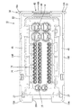
第1ハウジング10は合成樹脂製で、図18に示すように、略方形のブロック状をなしている。第1ハウジング10の内部には、同じく略方形のブロック状をなす本体部11が形成されている。本体部11の外周には、嵌合筒部12が形成されている。本体部11と嵌合筒部12との間には、両ハウジング10,20の嵌合に伴って、第2ハウジング20のフード部21が進入可能とされている。尚、スライダ30を後述する操作完了位置まで押し込んだ際には、両ハウジング10,20が完全に嵌り合った状態となって嵌合完了状態に至るとともに雄端子金具22が図示しない雌端子金具内に完全に嵌り込んで両端子金具が導通可能に接続されるようにされている。
The
嵌合筒部12を挟む上下両側には、一対のスライダ収容空間(本発明におけるスライダの進入路に相当する。)S,Sが配されている。スライダ収容空間Sは、第1ハウジング10内を幅方向に貫通して設けられ、スライダ30が幅方向両側から組み付け可能とされている。また、嵌合筒部12の内周面における幅方向両側には、一対の案内凹部12A,12Aが前後方向に沿って凹設されている。案内凹部12Aは、第2ハウジング20の案内突部24が内部に進入可能とされており、両ハウジング10,20の誤嵌合防止が行われるようになっている。
A pair of slider housing spaces (corresponding to a slider entry path in the present invention) S, S are arranged on both upper and lower sides sandwiching the
本体部11の内部には、大きさの異なる3種類の複数のキャビティ14が前後方向に貫通して形成されている。これらのキャビティ14の内部には、後方から3種類の雌端子金具が挿入可能とされており、正規位置まで挿入されるとキャビティ14の内部において前方に突出する片持ち状をなすランス14Aによって抜止め状態に保持されるようになっている。また、本体部11の前面には、横長略方形の孔形状をなす嵌合挿通孔15が開口している。嵌合挿通孔15には、第2ハウジング20の案内片23が進入可能とされている。本体部11の前面には、図10に示すように、フロントキャップ16が冠着可能とされている。フロントキャップ16には、キャビティ14に対応する貫通孔16Aと、嵌合挿通孔15に対応する貫通孔16Bとが形成されている。
Inside the
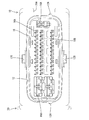
第1ハウジング10の後面(背面)における外周縁部には、図16に示すように、後述する検知位置にある検知部材40を収容するための収容部26が配されている。収容部26は、各キャビティ14を取り囲む位置に配される内周壁18と、その内周壁18の外方に配される外周壁19との間に形成されている。外周壁19は、第1ハウジング10の後面における四隅において水平部分と鉛直部分とからなる図示4個のL字部19Aと、幅方向に隣り合う一対のL字部19Aの水平部分間に配され、かつ上下方向に対向して一対配される回動支持部19Bとから構成される。外周壁19の突出高さは、検知部材40の後述するアーム部45の前後方向における厚さとほぼ同一とされ、図1に示すように、検知部材40が収容部26に嵌り込んだ状態(後述する検知位置にある状態)では、アーム部45の後端縁が外周壁19の後端縁より後方にはみ出さないようにされている。
As shown in FIG. 16, an
L字部19Aの鉛直部分は、第1ハウジング10の幅方向両側面よりも外方に突出した位置に配されている。スライダ30が操作完了位置にあるときには、図1に示すように、L字部19Aの鉛直部分の下方にスライダ30の操作部33が嵌り込んで、外周壁19の外側面と操作部33の外面とがほぼ面一をなすようにされている。尚、操作完了位置とは、図1に示すスライダ30の操作位置であって、後述する操作部33の内面がスライダ収容空間Sの開口縁部13Bに当接して、これ以上押し込み操作ができない位置をいう。
The vertical portion of the L-shaped
L字部19Aの水平部分と内周壁18との間には、図16に示すように、挿通孔27が前後方向に貫通して設けられている。挿通孔27は略方形の孔形状をなし、挿通孔27を通じて検知部材40の後述する検知リブ41を挿通可能としている。尚、回動支持部19Bの幅方向両側には、後述する係止凹部53と逃がし空間52の幅方向両端部を成形するための型抜き孔が開口しており、その型抜き孔を通じて図示しない解除治具を挿入し、スライダ30が待機位置にあるときに係止突起32Aの切り立った面と係止凹部53の切り立った面との係止状態を解除してスライダ30を引く抜くことが可能とされている。
As shown in FIG. 16, an
L字部19Aの水平部分において挿通孔27と隣接する位置には、円孔のロック受け部19Dが上下方向に貫通して設けられている。ロック受け部19Dにおいて収容部26側の孔縁部には、検知部材40の後述するロック部42が収容部26側から係止可能とされている。また、回動支持部19Bの幅方向中央には、円孔の軸孔19Cが上下方向に貫通して設けられている。軸孔19Cには、検知部材40の後述する回動軸片43が収容部26側から嵌り込んで検知部材40を回動可能に軸支するようにされている。回動支持部19Bは、スライダ30の組み付け方向に応じて検知部材40の付け替えができるようになっており、本実施形態においては、いずれの組み付け位置に対しても軸孔19Cが共用されるようになっている。
At a position adjacent to the
収容部26において上下方向に隣り合う一対のL字部19Aの鉛直部分間は、えぐられることで凹部26Aが形成されている。凹部26Aには、検知部材40の回動操作に伴って、検知部材40の後述する押圧部44が嵌り込むようになっている。こうして、検知部材40が収容部26内に収容された状態(後述する検知位置にある状態)では、検知部材40の押圧部44の外側面と外周壁19の幅方向外側面とスライダ30の操作部33の外面とが面一をなすようにされている。したがって、図8に示す第1ハウジング10の背面側から見た場合でも検知部材40が後述する検知位置に至ったことを認識することが可能とされている。
In the
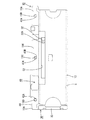
スライダ収容空間Sは、図17に示すように、側方から見ると略方形の孔形状をなし、嵌合筒部12を挟んで上下一対設けられている。スライダ収容空間Sを構成する各壁面(以下、空間構成部13という。)のうち第1ハウジング10の後面側と嵌合筒部12側との間の角部には、幅方向に沿ってテーパ面13Aが形成されている。テーパ面13Aは、スライダ30をスライダ収容空間Sにスライド挿入するときにスライダ30が上下反転した姿勢で挿入されることを規制するためのものであり、正規姿勢で挿入された時には後述するカム板31の切欠き面31Aと対面して挿入を許容し、正規姿勢以外ではカム板31の先端とスライダ収容空間Sの開口縁部13Bとが干渉して挿入を規制するようにされている。
As shown in FIG. 17, the slider accommodating space S has a substantially square hole shape when viewed from the side, and is provided with a pair of upper and lower sides with the
また、第1ハウジング10の幅方向両側面の略中央には、サイドリテーナ50を収容するためのリテーナ収容孔51が幅方向に貫通して設けられ、雌端子金具がキャビティ14内における正規挿入位置まで挿入された後、サイドリテーナ50をリテーナ収容孔51に挿入して雌端子金具の後端に係止させると、ランス14Aによる係止とともに二重係止された状態となって雌端子金具を抜止め状態に保持することが可能とされている。
In addition, a
第1ハウジング10の前面において両ハウジング10,20の嵌合時に第2ハウジング20のフォロアピン25と対応する位置には、逃がし溝12Bが形成されている。逃がし溝12Bは、図18に示すように、空間構成部13の幅方向中央において第1ハウジング10の前面側から嵌合筒部12側にかけてフォロアピン25の進入経路に沿って切り欠くことで、第1ハウジング10の前方空間とスライダ収容空間Sとを連通させている。これにより、フォロアピン25は、両ハウジング10,20の嵌合時に逃がし溝12Bを通じてスライダ収容空間Sの内部に進入することが可能とされている。
An
空間構成部13において嵌合筒部12と対向する側には、図13に示すように、幅方向に所定の間隔を空けて一対の係止凹部53,53が凹設されている。両係止凹部53,53は、逃がし溝12Bを上下方向に通る軸心に関して左右対称とされている。係止凹部53において幅方向に対向する両傾斜面のうち逃がし溝12Bと反対側の傾斜面は、スライダ30の挿入方向に対して直交する切り立った面とされ、同逃がし溝12B側の傾斜面は、緩やかな勾配をなしている。係止凹部53は、図14に示すように、スライダ30の後述する係止突起32Aが嵌り込んだ状態では、係止突起32Aの切り立った面が係止凹部53の切り立った面に係止することで抜け方向への移動を規制するとともに操作完了位置側への移動を許容しつつスライダ30を待機位置に保持可能とされている。尚、待機位置とは図3におけるスライダ30の挿入位置であって、第2ハウジング20のフォロアピン25を逃がし溝12Bを通じてカム溝34の入口34Aにそのまま受入可能な位置をいう。
As shown in FIG. 13, a pair of locking
空間構成部13において両係止凹部53,53間には、幅方向に沿って逃がし空間52が形成されている。スライダ収容空間Sは、逃がし空間52を通じて外部に露出した状態とされている。逃がし空間52は、スライダ30の後述する係止突起32Aが係止凹部53における逃がし溝12B側の傾斜面を乗り越えた後、スライダ30が操作完了位置に至るまでの間、係止突起32Aが空間構成部13と干渉するのを回避するためのものである。これにより、スライダ30の操作途上で操作力が増大することが規制される。また、逃がし空間52は、スライダ30が操作完了位置に至った状態において係止突起32Aが撓んだままとなるのを回避可能としている(図15参照)。
In the
スライダ30は合成樹脂製で、図20に示すように、幅方向に開いた略U字状をなし、操作部33と、その両端に配される一対のカム板31,31とから構成されている。カム板31は、図13ないし図15に示すように、スライダ収容空間Sの内部に嵌合可能とされている。本実施形態においてスライダ30は、スライダ収容空間Sの幅方向両側から組み付け可能とされており、第2ハウジング20との組み付け現場の状況に応じて組み付け方向を自由に選択可能とされている。カム板31の内面における後端(検知孔35側)には、図21に示すように、幅方向に沿って角部が切り欠かれることで切欠き面31Aが形成されている。
As shown in FIG. 20, the
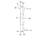
カム板31には、図19に示すように、第2ハウジング20のフォロアピン25と係合可能なカム溝34が形成されている。カム溝34はカム板31の厚さ方向に貫通する形態で設けられ、両ハウジング10,20を嵌合完了状態に至らしめるための作動領域37と、この作動領域37の奥側に連続し、かつ嵌合完了後のスライド操作によっても嵌合を進行させない遊び領域36とから構成されている。尚、カム溝34の内面側の孔縁部は、内方(板面方向と平行)に張り出し形成されており、この張り出し部分にはフォロアピン25のフランジ25Aが板厚方向外側から係止することで、両カム板31,31の開き止めを行うとともにフォロアピン25とカム溝34の係合状態を保持することが可能となっている。
As shown in FIG. 19, a
作動領域37は、カム板31の先端前面側に配される入口34Aから略中央部に向けて斜め方向(両ハウジング10,20の嵌合方向とスライダ30のスライド方向の双方に対して斜めをなす方向)に形成されている。これにより、スライダ30が待機位置にあるときに、第2ハウジング20のフォロアピン25をカム溝の入口34Aに進入させてスライダ30をスライド挿入することにより、フォロアピン25とカム溝34の係合によるカム作用によって両ハウジング10,20を嵌合完了状態に至らしめることが可能となっている。
The
遊び領域36は、作動領域37の終端からカム溝34の終端34Bに向けて全体としてスライダ30の挿入方向にほぼ沿うようにして設けられている。遊び領域36におけるカム溝34の前縁34Cは、カム溝34の終端34Bに向かうにつれてやや前方に向かう勾配をなしている。遊び領域36は、両ハウジング10,20の嵌合に寄与しないものの、両ハウジング10,20が嵌合完了状態にあるときに両ハウジング10,20が互いに引っ張られると、フォロアピン25が遊び領域36におけるカム溝34の前縁34Cに係合することで、スライダ30が操作完了位置へ押し込まれる方向に作用する分力を生じさせ、両ハウジング10,20の離脱を規制可能としている。また、フォロアピン25が遊び領域36内にあるときには、検知リブ41の検知孔35に対する押し込み操作を可能とし、後述する半挿入傾斜面41Aによるスライダ30の操作完了位置への矯正を可能としている。
The
カム板31においてカム溝34の後方には、図19に示すように、撓み係止片32が配されている。撓み係止片32は、カム板31の板厚方向に貫通して略U字状に切り欠くことで、カム板31の先端側を基端部として操作部33側が内外方向に撓み可能に形成されている。撓み係止片32の内方には、撓み係止片32の内面側を除肉することで、撓み係止片32の撓み空間が設けられている。また、撓み係止片32の自由端側における外面側には、係止突起32Aが外方に突出して形成されている。係止突起32Aは、図14に示すように、スライダ30をスライダ収容空間S内に挿入したときに、空間構成部13の係止凹部53に係止して、スライダ30を待機位置に保持することが可能となっている。
As shown in FIG. 19, a
両カム板31,31の長手方向の両側縁のうち第1ハウジング10の後面に位置する側であって操作部33寄りには、一対の検知孔35,35が後方に開口して形成されている。検知孔35は、図1に示すように、スライダ30が操作完了位置にあるときには、挿通孔27を通じて後述する検知リブ41を内部に収容可能としている。
A pair of detection holes 35, 35 are formed to open rearward on the side located on the rear surface of the
検知部材40は合成樹脂製で、図23に示すように、略「門」形をなし、押圧部44の両端に一対のアーム部45が配されている。また、検知部材40は、回動支持部19Bにより初期位置と検知位置との間を回動可能に設けられている。押圧部44の略中央には、外方に突出する形態の突部44Aが形成され、検知部材40が検知位置にあるときには、図8に示すように、突部44Aが上下方向に隣り合う一対のL字部19Aの鉛直部分間に嵌り込むようにされている。尚、初期位置とは、図3に示す検知部材40の位置であって、後述する検知リブ41がカム板31に干渉してスライダ収容空間S側に押し込めない位置をいう。一方、検知位置とは、図1に示す検知部材40の位置であって、スライダ30が操作完了位置に至ったときに初めて検知リブ41が検知孔35に整合してスライダ収容空間S側に押し込める位置をいう。
As shown in FIG. 23, the
アーム部45において押圧部44と反対側の端部には、回動軸片43が配されている。回動軸片43は、アーム部45を板厚方向(前後方向)に貫通して略U字状に切り欠いて薄肉に形成することで、操作部44側を基端部としてアーム部45の先端側が内外方向に撓み可能とされている。また、回動軸片43の自由端側の外面側には、略円柱状をなす回動軸43Aが外方に突出して設けられている。尚、回動軸43Aの先端において回動支持部19Bへの組み付け側には、同組み付けの際に外周壁19の内側面に摺接して回動軸片43を内方に撓ませるようにして円滑な組み付け操作を案内するためのテーパ状案内面43Bが設けられている。
A
一方、アーム部45の側面において押圧部44側の端部には、図22に示すように、ロック部42が配されている。ロック部42は、アーム部45を上下方向に貫通して略U字状に切り欠いて薄肉に形成することで、アーム部45の先端側を基端部として押圧部44側が内外方向に撓み可能とされている。また、ロック部42の自由端側の外面側には、略円錐状をなすロック突部42Aが外方に突出して設けられている。ロック突部42Aは、検知部材40が検知位置へ回動されるに伴って外周壁19の内側面に摺接してロック部42を内方に撓ませつつロック受け部19Dに嵌り込むことで検知部材40を解除可能に検知位置に保持することが可能とされている。
On the other hand, as shown in FIG. 22, a
アーム部45の下面においてロック部42と隣接する位置には、図22に示すように、検知リブ41が配されている。検知リブ41は、アーム部45の長さ方向とほぼ直交する方向に突出し、検知部材40が検知位置に回動されると回動軌跡を描きつつ挿通孔27を通じてスライダ収容空間S内に進入可能とされている。また、検知リブ41の先端は、スライダ30の操作途上ではカム板31に干渉してスライダ収容空間S側に入り込めないものの、スライダ30が操作完了位置にあるときには検知孔35に整合して内部に収容されるようになっている。これにより、検知部材40の押し込み操作が許容されることをもってスライダ30が操作完了位置にあることを検知するとともに両ハウジング10,20の嵌合完了状態を検知することができるようになっている。
As shown in FIG. 22, a
検知リブ41において回動軸片43側の側面には、半挿入矯正面41Aが配されている。半挿入矯正面41Aは、検知リブ41の先端側に向かうにつれて回動軸43Aから離間するような勾配をもって形成されている。検知孔35の孔縁部は、両ハウジング10,20の嵌合完了状態であってスライダ30が半挿入状態(フォロアピン25が遊び領域36内)にあるときには、図5に示すように、検知部材40の押し込みに伴って検知リブ41の半挿入矯正面41Aが摺接することで、スライダ30を操作完了位置へ押し込む方向に作用する分力を生じさせて、スライダ30を操作完了位置に押し込めるようになっている。逆に、操作完了位置にあるスライダ30を抜け方向にスライド操作すると、検知リブ41の半挿入矯正面41Aが検知孔35の孔縁部に摺接しつつ検知孔35から押し出されて、検知部材40が初期位置に至るようにされている。尚、アーム部45において収容部26と対向する面のうち回動軸43Aより先端側はテーパ状に形成され、図7に示すように、検知部材40が初期位置にあるときに、収容部26と干渉しないようにされている。
A
本実施形態は以上のような構造であって、続いてその作用を説明する。
まず、スライダ30を第1ハウジング10に組み付ける。スライダ30は、図13に示すように、スライダ収容空間Sの幅方向両側から組み付け可能とされ、第2ハウジング20との組み付け現場の状況に応じて組み付け方向を自由に選択することができる。組み付けに際しては、図9に示すように、カム板31の切欠き面31Aが空間構成部13のテーパ面13Aと対面するようにして組み付ける。これにより、スライダ30が上下反転した姿勢で挿入されることが規制され、そのままスライダ30を操作完了位置までスライド挿入する。
The present embodiment has the above-described structure, and the operation thereof will be described subsequently.
First, the
次に、検知部材40を第1ハウジング10に組み付ける。検知部材40は、押圧部44が軸孔19Cを上下方向に通る軸心に関してスライダ30の操作部33と同じ側となるようにして組み付ける。そして、テーパ状案内面43Bを外周壁19の内側面に摺接させつつ回動軸片43を内方に撓ませ、回動軸43Aが軸孔19Cに嵌まるとともに回動軸片43を復帰させて、検知部材40が回動支持部19Bに回動可能に組み付けられる。そして、押圧部44を押圧して検知部材40をスライド収容空間S側に押し込むと、ロック突部42Aが外周壁19の内側面に摺接しつつロック部42を内方に撓ませ、ロック突部42Aがロック受け部19Dに嵌まるとともにロック部42を復帰させて、検知部材40が検知位置において解除可能に保持される。こうして、検知リブ41が、図1に示すように、挿通孔27を通じて検知孔35の内部に収容されるとともに、検知部材40が、図8に示すように、収容部26内に収容される。
Next, the
第1ハウジング10は、スライダ収容空間Sにおいてスライダ30が操作完了位置に挿入された状態で、第2ハウジング20との組み付け現場へと送られる。第2ハウジング20との組み付けに際しては、操作完了位置にあるスライダ30は、一旦、待機位置まで引き戻される。この引き戻しに際しては、検知リブ41の半挿入矯正面41Aは、図2に示すように、検知孔35の孔縁部に摺接することで、検知リブ41を検知孔35から押し出す方向に作用する分力を生じさせる。そして、ロック突部42Aとロック受け部19Dによるロックが解除されて、スライダ30が待機位置に至ると、図3に示すように、検知リブ41がカム板31に乗り上げて検知部材40が初期位置に至る。スライダ30が待機位置にあるときには、係止突起32Aの切り立った面が係止凹部53の切り立った面に係止することでスライダ30の抜け方向への移動が規制されるとともに、係止突起32Aが係止凹部53の緩やかな勾配をなす傾斜面に解除可能に係止することでスライダ30が不用意に待機位置から操作完了位置へ移動することが規制される。カム溝34の入口34Aは、スライダ30が待機位置にあるときには、逃がし溝12Bと整合する位置に配され、フォロアピン25との係合に備えて待機する。
The
続いて、両ハウジング10,20の嵌合を行う。まず、第2ハウジング20の案内突部24が第1ハウジング10の案内凹部12Aに進入するようにして第1ハウジング10を第2ハウジング20側に向けて浅く嵌合させる。これにより、第1ハウジング10が第2ハウジング20に対して上下反転した姿勢で挿入されることが規制されるとともに円滑な嵌合案内が行われる。そして、フォロアピン25を、図3に示すように、逃がし溝12Bを通じてカム溝34の入口34Aへと進入させる。引き続き、スライダ30を操作完了位置に向けて押し込むと、係止突起32Aと係止凹部53の傾斜面との係止状態が解除されてスライダ30の移動が許容され、フォロアピン25とカム溝34の係合によるカム作用によって両ハウジング10,20の嵌合が進行する。係止突起32Aは、図11に示すように、係止凹部53の傾斜面を乗り越えた後、逃がし空間52に嵌り込むことにより、係止突起32Aと空間構成部13が干渉してスライダ30の操作途上における操作力が増大することが回避される。また、図3に示す両ハウジング10,20の嵌合途上では、初期位置にある検知リブ41の先端がカム板31に干渉してスライダ収容空間S側への押し込み操作が規制されるようになっている。
Subsequently, the
スライダ30のスライド操作に伴って両ハウジング10,20が嵌合完了状態に至るとフォロアピン25が遊び領域36内に進入する(図4参照)。両ハウジング10,20の嵌合完了状態では、初期位置にある検知部材40の検知孔35への押し込み操作が許容される。検知部材40が初期位置にあるときおよび検知位置に向かう途上では、押圧部44を特定部位として第1ハウジング10の後面側に投影させたときに、押圧部44を投影させた部位と凹部26Aが不整合となって検知部材40が検知位置に至る前であることが外観により容易に判断することが可能とされている。検知部材40を検知位置に向けて押し込むと、図5に示すように、検知リブ41の先端が挿通孔27を通じて検知孔35の内部に進入し、検知リブ41の半挿入矯正面41Aが検知孔35の孔縁部に摺接してスライダ30を操作完了位置に押し込むことができる。この間、フォロアピン25は、遊び領域36内をカム溝34の終端34Bに向けて移動し、スライダ30を操作完了位置まで押し込めることをもって、両ハウジング10,20が嵌合完了状態に至ったことを保証することができる。
When the two
検知部材40が検知位置に至るとともにスライダ30が操作完了位置に至ると、検知リブ41は、図6に示すように、検知孔35と整合して内部に収容される。また、検知部材40は、ロック突部42Aがロック受け部19Dに係止することにより、検知位置において解除可能に保持される。尚、スライダ30を操作完了位置まで挿入した後に、検知部材40を検知位置に向けて押し込むことも当然可能である。ここで、本実施形態においては、次に示す3点から、両ハウジング10,20の嵌合完了状態を外観により容易に判断することができるようになっている。一つ目は、検知部材40を回動操作に伴って検知位置に至らしめると、図8に示すように、押圧部44の突部44A(特定部位)を第1ハウジング10の後面側に投影させた位置が凹部26Aの位置と整合となる点。二つ目は、検知部材40が検知位置にあるときに、L字部19Aの幅方向外側面とスライダ30の操作部33の外面と押圧部44の突部44Aの幅方向外側面とが面一となる点。三つ目は、図6に示すように、アーム部45の後端縁が外周壁19の後端縁から後方にはみ出さないとともに、操作部33がL字部19Aの鉛直部分(外方に突出した部分)の下方に嵌り込む点。
When the
次に、両ハウジング10,20を離脱する操作について説明する。両ハウジング10,20の離脱にあたっては、スライダ30を抜け方向にスライド操作し、検知リブ41の半挿入矯正面41Aを検知孔35の孔縁部に摺接させることにより検知リブ41が検知孔35から押し出されてカム板35に乗り上げ、検知部材40が初期位置に至る(図7参照)。したがって、離脱操作に先立って検知位置にある検知部材40を初期位置に押し上げる作業が不要となり、作業効率を向上させることができる。そして、図7の状態からスライダ30を抜け方向に移動させると、フォロアピン25とカム溝34の係合によるカム作用によって両ハウジング10,20の離脱が進行し、スライダ30が待機位置に到達したときには、フォロアピン25がカム溝34の入口34Aに位置し、両ハウジング10,20をそのまま引き離すことが可能となる。
Next, an operation for removing both the
以上のように、本実施形態においては、以下に示す効果を発揮することができる。
1.検知部材40は、第1ハウジング10の外面に露出した状態で回動可能に組み付けられているから、第1ハウジング10の背面側から検知部材40の検知操作を確認する場合であっても視線を横切るようにして移動し検知操作を確認しやすくなる。すなわち、平行移動の場合には、検知部材40が検知位置に至ったか否かを外観判断する作業者の視線が検知部材40の移動方向背面側に存在する場合には、検知部材40の特定部位(本実施形態においては、例えば押圧部44の突部44Aが特定部位に該当する。)を第1ハウジング10側に投影しても、検知部材40が初期位置にあるときも検知位置にあるときも投影位置のずれがないため、作業者は検知位置と初期位置の差を認識できない。しかし、回動形態を採用すれば、仮に視線が上記のような位置にあったとしても、初期位置と検知位置との間では投影位置にずれを生じさせることができるため、検知部材40が検知位置に至ったか否かを明確に認識することができる。
As described above, in the present embodiment, the following effects can be exhibited.
1. Since the
2.検知部材40は、スライダ30の操作途上では検知リブ41がスライダ30に摺接してスライダ収容空間S側に押し込めないものの、スライダ30が操作完了位置に至ったときに初めて検知リブ41が検知孔35に整合して検知位置に至るまで押し込めるから、検知部材40が検知位置に至ったことを確実に検知することができる。
3.検知リブ41には、半挿入矯正面41Aが設けられるから、検知部材40を押し込むことでスライダ30の半挿入状態を矯正して操作完了位置へ押し込むことができるとともに、操作完了位置にあるスライダ30を抜け方向に引き抜くことで検知リブ41を検知孔35から自動的に押し出すことができるから、別途検知部材40を検知位置から初期位置に押し上げる操作が不要となり、作業効率を向上させることができる。
4.カム溝34は、両ハウジング10,20を嵌合完了状態に至らしめるための作動領域37と、この作動領域37の奥側に連続し、かつ嵌合完了後のスライド操作によっても嵌合を進行させない遊び領域36とからなるから、フォロアピン25が遊び領域36にある間に検知部材40が検知孔35に収容されることをもって、両ハウジング10,20の嵌合完了状態を保証することができる。また、嵌合完了状態において両ハウジング10,20が互いに引っ張られると、フォロアピン25と遊び領域36におけるカム溝34の前縁34Cとが係合してスライダ30を操作完了位置へ向かう方向に作用する分力を生じさせるから、嵌合完了状態を保持することができる。
2. Although the
3. Since the
4). The
5.スライダ収容空間Sは、第1ハウジング10を幅方向に貫通して設けて、その両側から選択的に組み付け可能とされ、第1ハウジング10には、スライダ30の組み付け方向に応じて組み付け位置を選択可能とする回動支持部19Bが対称位置に配されているから、両ハウジング10,20の組み付け現場の状況に応じて、スライダ30の組み付け方向を自由に選択することができる。
6.回動支持部19Bは共用され、スライダ30の組み付け方向に応じて付け替えができるようになっているから、軸孔19Cを個別に2箇所設ける必要がなく、構造を簡素化し、省スペース化することができる。
7.検知部材40は、検知位置に至ると第1ハウジング10と係止して戻り方向への回動をロックする回動規制手段を設けたから、検知位置にある検知部材40が不用意に回動してしまうことが規制される。
8.回動規制手段は、検知部材40に撓み可能に設けられたロック部42と、第1ハウジング10に配され、ロック部42が乗り越えて復帰することにより係止するロック受け部19Dとから構成されるから、ロック部42とロック受け部19Dが係止し合う際の節度感によっても検知操作の確認が可能である。
5. The slider housing space S is provided so as to penetrate the
6). Since the
7). When the
8). The rotation restricting means includes a
<他の実施形態>
本発明は上記記述及び図面によって説明した実施形態に限定されるものではなく、例えば次のような実施形態も本発明の技術的範囲に含まれ、さらに、下記以外にも要旨を逸脱しない範囲内で種々変更して実施することができる。
<Other embodiments>
The present invention is not limited to the embodiments described with reference to the above description and drawings. For example, the following embodiments are also included in the technical scope of the present invention, and further, within the scope not departing from the gist of the invention other than the following. Various modifications can be made.
(1)本実施形態によると、検知リブ41が検知部材40に設けられているものを例示しているが、本発明によると、検知リブ41は、スライダ30に設けるようにしてもよく、その場合には、検知部材40に検知孔35を設けるようにする。このようにすると、スライダ30に孔を設ける必要がなく、スライダ30の強度を確保することができる。
(1) According to the present embodiment, the
(2)本実施形態によると、フォロアピン25と遊び領域36におけるカム溝34の前縁34Cとが係合することでスライダ30が操作完了位置へ向かう方向に作用する分力を生じさせるようにしてあるが、本発明によると、遊び領域36は嵌合に寄与しないものであればよく、例えば、遊び領域36におけるカム溝34の前縁34Cは、スライダ30のスライド方向と平行としてもよい。
(2) According to the present embodiment, the
(3)本実施形態によると、フォロアピン25が遊び領域36内にあるときに、半挿入矯正面41Aによる半挿入矯正を行うようにしているが、本発明によると、フォロアピン25が作動領域37にあるとき、すなわち、両ハウジング10,20の嵌合途上にあるときに半挿入矯正が行われるようにしてもよい。
(3) According to the present embodiment, when the
(4)本実施形態によると、検知部材40に回動軸43Aを設けているが、本発明によると、回動軸43Aを第1ハウジング10に設け、軸孔19Cをスライダ30に設けるようにしてもよい。この場合には、回動軸43Aを共用としてもよい。
(4) According to the present embodiment, the
(5)本実施形態によると、検知部材40にロック部42を設けているが、本発明によると、ロック部42を第1ハウジング10に設け、ロック受け部19Dを検知部材40に設けるようにしてもよい。
(5) According to the present embodiment, the
(6)本実施形態によると、回動規制手段は、撓み可能なロック部42がロック受け部19Dを乗り越えて復帰することにより係止する構成のものを例示しているが、本発明によると、他の手段であってもよく、例えば、ロック部42とロック受け部19Dの間に圧縮可能なゴム材を介在させて摩擦抵抗により検知部材40の回動操作をロックするようにしてもよい。
(6) According to the present embodiment, the rotation restricting means is exemplified by a structure in which the
(7)本実施形態では、検知孔35をスライダ30に設けたものを例示しているが、本発明によると、検知部材40が回動可能であれば、他の形態であってもよく、検知孔35を第2ハウジング20のフード部21に形成し、両ハウジング10,20の嵌合途上では、検知リブ41がフード部21の外面に摺接して押し込めないようにし、嵌合完了状態に至ったときに初めて検知リブ41が検知孔35に進入して検知部材40を押し込めるようにしてもよい。
(7) In the present embodiment, the
10…第1ハウジング
19B…回動支持部
19D…ロック受け部
20…第2ハウジング
25…フォロアピン
30…スライダ
34…カム溝
35…検知孔
36…遊び領域
37…作動領域
40…検知部材
41…検知リブ
41A…半挿入矯正面
42…ロック部
43A…回動軸
S…スライダ収容空間(スライダの進入路)
DESCRIPTION OF
Claims (8)
前記第1ハウジングの外面には、前記検知位置にある前記検知部材が嵌り込む収容部が設けられ、前記検知位置では前記検知部材が前記収容部の外部にはみ出さないようにされており、
前記検知部材は前記第1ハウジングの外面に露出した状態で前記第1ハウジングに対して回動可能に組み付けられていることを特徴とするコネクタ。 A first housing, a second housing that can be fitted to the first housing and having a follower pin, and is assembled to the first housing so as to be slidable from a direction perpendicular to the fitting direction of the two housings; and A slider having a cam groove engageable with the follower pin, and causing the two housings to be fitted by a cam action by the engagement of the follower pin and the cam groove by the sliding operation, thereby achieving a fitting completion state. And a detection member that is assembled to the first housing and that is restricted from moving to the detection position during operation of the slider and is allowed to move to the detection position at the operation completion position of the slider. There,
The outer surface of the first housing is provided with a receiving portion into which the detection member at the detection position is fitted, and the detection member is prevented from protruding outside the storage portion at the detection position.
The connector, wherein the detection member is rotatably attached to the first housing in a state where the detection member is exposed on an outer surface of the first housing .
Priority Applications (4)
| Application Number | Priority Date | Filing Date | Title |
|---|---|---|---|
| JP2006048672A JP4655960B2 (en) | 2006-02-24 | 2006-02-24 | connector |
| DE602007000203T DE602007000203D1 (en) | 2006-02-24 | 2007-02-14 | Electrical connector |
| EP07003170A EP1826877B1 (en) | 2006-02-24 | 2007-02-14 | Electrical connector |
| US11/710,668 US7419392B2 (en) | 2006-02-24 | 2007-02-23 | Connector and connector assembly |
Applications Claiming Priority (1)
| Application Number | Priority Date | Filing Date | Title |
|---|---|---|---|
| JP2006048672A JP4655960B2 (en) | 2006-02-24 | 2006-02-24 | connector |
Publications (2)
| Publication Number | Publication Date |
|---|---|
| JP2007227236A JP2007227236A (en) | 2007-09-06 |
| JP4655960B2 true JP4655960B2 (en) | 2011-03-23 |
Family
ID=37903509
Family Applications (1)
| Application Number | Title | Priority Date | Filing Date |
|---|---|---|---|
| JP2006048672A Expired - Fee Related JP4655960B2 (en) | 2006-02-24 | 2006-02-24 | connector |
Country Status (4)
| Country | Link |
|---|---|
| US (1) | US7419392B2 (en) |
| EP (1) | EP1826877B1 (en) |
| JP (1) | JP4655960B2 (en) |
| DE (1) | DE602007000203D1 (en) |
Families Citing this family (8)
| Publication number | Priority date | Publication date | Assignee | Title |
|---|---|---|---|---|
| DE102007019713A1 (en) * | 2007-04-26 | 2008-10-30 | Tyco Electronics Amp Gmbh | Connector with position safety |
| JP2009252488A (en) * | 2008-04-04 | 2009-10-29 | Tyco Electronics Amp Kk | Lever type connector |
| JP2014017135A (en) * | 2012-07-10 | 2014-01-30 | Tyco Electronics Japan Kk | Connector |
| JP6119670B2 (en) * | 2014-05-27 | 2017-04-26 | 住友電装株式会社 | connector |
| FR3033091B1 (en) * | 2015-02-25 | 2018-05-25 | Amphenol - Air Lb | CONNECTOR CONNECTION SYSTEM |
| JP7209192B2 (en) * | 2019-11-15 | 2023-01-20 | 住友電装株式会社 | connector |
| JP7252519B2 (en) * | 2020-01-13 | 2023-04-05 | 住友電装株式会社 | connector |
| JP7290116B2 (en) * | 2020-01-13 | 2023-06-13 | 住友電装株式会社 | connector |
Citations (8)
| Publication number | Priority date | Publication date | Assignee | Title |
|---|---|---|---|---|
| JPH04206370A (en) * | 1990-11-30 | 1992-07-28 | Yazaki Corp | Connector with cam member for fitting operation |
| JPH10247552A (en) * | 1997-03-05 | 1998-09-14 | Yazaki Corp | Lif connector |
| JPH11250985A (en) * | 1998-03-04 | 1999-09-17 | Yazaki Corp | Connector fitting structure |
| JP2000200655A (en) * | 1999-01-05 | 2000-07-18 | Sumitomo Wiring Syst Ltd | Connector |
| JP2002359030A (en) * | 2001-06-01 | 2002-12-13 | Sumitomo Wiring Syst Ltd | Connector |
| JP2003100386A (en) * | 2001-09-25 | 2003-04-04 | Yazaki Corp | Lever engagement type power-source circuit breaker |
| JP2003133003A (en) * | 2001-10-29 | 2003-05-09 | Sumitomo Wiring Syst Ltd | Connector |
| JP2003338344A (en) * | 2002-05-20 | 2003-11-28 | Sumitomo Wiring Syst Ltd | Lever type connector |
Family Cites Families (14)
| Publication number | Priority date | Publication date | Assignee | Title |
|---|---|---|---|---|
| US5238417A (en) * | 1990-12-15 | 1993-08-24 | Yazaki Corporation | Connector with a lever |
| DE19511225C5 (en) * | 1995-03-27 | 2008-02-07 | Robert Bosch Gmbh | Electrical plug device |
| DE19530334B4 (en) | 1995-08-17 | 2006-03-02 | The Whitaker Corp., Wilmington | Plug arrangement with an actuating slide |
| JP3315314B2 (en) * | 1996-05-30 | 2002-08-19 | 矢崎総業株式会社 | Low insertion force connector |
| JP3446990B2 (en) | 1997-06-04 | 2003-09-16 | 矢崎総業株式会社 | Connector lock detection structure |
| DE19802554A1 (en) * | 1998-01-23 | 1999-08-05 | Whitaker Corp | Connector arrangement with an operating slide |
| US6254407B1 (en) | 1999-02-17 | 2001-07-03 | Framatome Connectors Interlock, Inc. | Mechanical assist cam slide device |
| ES1044100Y (en) * | 1999-08-06 | 2000-08-16 | Mecanismos Aux Ind | ANCHORAGE SYSTEM FOR CONNECTOR BOX IN SERVICE BOXES. |
| DE29921536U1 (en) * | 1999-12-08 | 2001-04-12 | Robert Bosch Gmbh, 70469 Stuttgart | Electrical connector with operating lever |
| US6666697B2 (en) * | 2001-10-29 | 2003-12-23 | Sumitomo Wiring Systems, Ltd. | Connector assembly |
| JP3887693B2 (en) * | 2001-11-12 | 2007-02-28 | 住友電装株式会社 | Lever type connector |
| JP2003331983A (en) * | 2002-05-14 | 2003-11-21 | Sumitomo Wiring Syst Ltd | Lever connector |
| US6824406B1 (en) * | 2003-06-26 | 2004-11-30 | Delphi Technologies, Inc. | Electrical connector assembly |
| JP2005116366A (en) * | 2003-10-08 | 2005-04-28 | Sumitomo Wiring Syst Ltd | Connector |
-
2006
- 2006-02-24 JP JP2006048672A patent/JP4655960B2/en not_active Expired - Fee Related
-
2007
- 2007-02-14 DE DE602007000203T patent/DE602007000203D1/en active Active
- 2007-02-14 EP EP07003170A patent/EP1826877B1/en not_active Not-in-force
- 2007-02-23 US US11/710,668 patent/US7419392B2/en not_active Expired - Fee Related
Patent Citations (8)
| Publication number | Priority date | Publication date | Assignee | Title |
|---|---|---|---|---|
| JPH04206370A (en) * | 1990-11-30 | 1992-07-28 | Yazaki Corp | Connector with cam member for fitting operation |
| JPH10247552A (en) * | 1997-03-05 | 1998-09-14 | Yazaki Corp | Lif connector |
| JPH11250985A (en) * | 1998-03-04 | 1999-09-17 | Yazaki Corp | Connector fitting structure |
| JP2000200655A (en) * | 1999-01-05 | 2000-07-18 | Sumitomo Wiring Syst Ltd | Connector |
| JP2002359030A (en) * | 2001-06-01 | 2002-12-13 | Sumitomo Wiring Syst Ltd | Connector |
| JP2003100386A (en) * | 2001-09-25 | 2003-04-04 | Yazaki Corp | Lever engagement type power-source circuit breaker |
| JP2003133003A (en) * | 2001-10-29 | 2003-05-09 | Sumitomo Wiring Syst Ltd | Connector |
| JP2003338344A (en) * | 2002-05-20 | 2003-11-28 | Sumitomo Wiring Syst Ltd | Lever type connector |
Also Published As
| Publication number | Publication date |
|---|---|
| US20070199369A1 (en) | 2007-08-30 |
| DE602007000203D1 (en) | 2008-12-11 |
| JP2007227236A (en) | 2007-09-06 |
| US7419392B2 (en) | 2008-09-02 |
| EP1826877B1 (en) | 2008-10-29 |
| EP1826877A1 (en) | 2007-08-29 |
Similar Documents
| Publication | Publication Date | Title |
|---|---|---|
| JP4655960B2 (en) | connector | |
| JP5029872B2 (en) | Lever type connector | |
| JP4492449B2 (en) | Lever type connector | |
| JP3813836B2 (en) | Half-mating prevention connector | |
| US7201591B2 (en) | Lever-type connector | |
| JP4941064B2 (en) | Lever type connector | |
| JP5939470B2 (en) | connector | |
| JP2006216308A (en) | Connector | |
| US10468821B2 (en) | Lever-type connector | |
| JP2007317442A (en) | Connector | |
| JP4462893B2 (en) | Pipe fitting | |
| JP5662210B2 (en) | Lever jig and connector device | |
| JP3986062B2 (en) | connector | |
| JP2003086301A (en) | Lever type connector | |
| JP2017216067A (en) | connector | |
| JP5329339B2 (en) | connector | |
| JP2010027392A (en) | Connector | |
| JP4215066B2 (en) | connector | |
| JP3677681B2 (en) | connector | |
| JP2002008779A (en) | Connector | |
| JP4631730B2 (en) | connector | |
| JP5257347B2 (en) | connector | |
| JP2005116471A (en) | Connector | |
| JP2010040376A (en) | Connector | |
| EP3726663A1 (en) | Grommet-equipped connector |
Legal Events
| Date | Code | Title | Description |
|---|---|---|---|
| A621 | Written request for application examination |
Free format text: JAPANESE INTERMEDIATE CODE: A621 Effective date: 20080627 |
|
| RD02 | Notification of acceptance of power of attorney |
Free format text: JAPANESE INTERMEDIATE CODE: A7422 Effective date: 20091002 |
|
| RD04 | Notification of resignation of power of attorney |
Free format text: JAPANESE INTERMEDIATE CODE: A7424 Effective date: 20091002 |
|
| A977 | Report on retrieval |
Free format text: JAPANESE INTERMEDIATE CODE: A971007 Effective date: 20100716 |
|
| A131 | Notification of reasons for refusal |
Free format text: JAPANESE INTERMEDIATE CODE: A131 Effective date: 20100803 |
|
| A521 | Request for written amendment filed |
Free format text: JAPANESE INTERMEDIATE CODE: A523 Effective date: 20100917 |
|
| TRDD | Decision of grant or rejection written | ||
| A01 | Written decision to grant a patent or to grant a registration (utility model) |
Free format text: JAPANESE INTERMEDIATE CODE: A01 Effective date: 20101130 |
|
| A01 | Written decision to grant a patent or to grant a registration (utility model) |
Free format text: JAPANESE INTERMEDIATE CODE: A01 |
|
| A61 | First payment of annual fees (during grant procedure) |
Free format text: JAPANESE INTERMEDIATE CODE: A61 Effective date: 20101213 |
|
| FPAY | Renewal fee payment (event date is renewal date of database) |
Free format text: PAYMENT UNTIL: 20140107 Year of fee payment: 3 |
|
| R150 | Certificate of patent or registration of utility model |
Free format text: JAPANESE INTERMEDIATE CODE: R150 |
|
| LAPS | Cancellation because of no payment of annual fees |