JP2010027392A - Connector - Google Patents

Connector Download PDF

Info

Publication number
JP2010027392A
JP2010027392A JP2008187455A JP2008187455A JP2010027392A JP 2010027392 A JP2010027392 A JP 2010027392A JP 2008187455 A JP2008187455 A JP 2008187455A JP 2008187455 A JP2008187455 A JP 2008187455A JP 2010027392 A JP2010027392 A JP 2010027392A
Authority
JP
Japan
Prior art keywords
dummy connector
main body
male
housing
connector main
Prior art date
Legal status (The legal status is an assumption and is not a legal conclusion. Google has not performed a legal analysis and makes no representation as to the accuracy of the status listed.)
Granted
Application number
JP2008187455A
Other languages
Japanese (ja)
Other versions
JP5211906B2 (en
Inventor
Yuuka Kobayashi
祐佳 小林
Current Assignee (The listed assignees may be inaccurate. Google has not performed a legal analysis and makes no representation or warranty as to the accuracy of the list.)
Sumitomo Wiring Systems Ltd
Original Assignee
Sumitomo Wiring Systems Ltd
Priority date (The priority date is an assumption and is not a legal conclusion. Google has not performed a legal analysis and makes no representation as to the accuracy of the date listed.)
Filing date
Publication date
Application filed by Sumitomo Wiring Systems Ltd filed Critical Sumitomo Wiring Systems Ltd
Priority to JP2008187455A priority Critical patent/JP5211906B2/en
Priority to DE102009030307.3A priority patent/DE102009030307B4/en
Priority to CN200910151764XA priority patent/CN101662096B/en
Priority to US12/501,664 priority patent/US7850469B2/en
Publication of JP2010027392A publication Critical patent/JP2010027392A/en
Application granted granted Critical
Publication of JP5211906B2 publication Critical patent/JP5211906B2/en
Active legal-status Critical Current
Anticipated expiration legal-status Critical

Links

Images

Classifications

    • HELECTRICITY
    • H01ELECTRIC ELEMENTS
    • H01RELECTRICALLY-CONDUCTIVE CONNECTIONS; STRUCTURAL ASSOCIATIONS OF A PLURALITY OF MUTUALLY-INSULATED ELECTRICAL CONNECTING ELEMENTS; COUPLING DEVICES; CURRENT COLLECTORS
    • H01R13/00Details of coupling devices of the kinds covered by groups H01R12/70 or H01R24/00 - H01R33/00
    • H01R13/44Means for preventing access to live contacts
    • H01R13/443Dummy plugs
    • HELECTRICITY
    • H01ELECTRIC ELEMENTS
    • H01RELECTRICALLY-CONDUCTIVE CONNECTIONS; STRUCTURAL ASSOCIATIONS OF A PLURALITY OF MUTUALLY-INSULATED ELECTRICAL CONNECTING ELEMENTS; COUPLING DEVICES; CURRENT COLLECTORS
    • H01R13/00Details of coupling devices of the kinds covered by groups H01R12/70 or H01R24/00 - H01R33/00
    • H01R13/46Bases; Cases
    • H01R13/52Dustproof, splashproof, drip-proof, waterproof, or flameproof cases
    • H01R13/5213Covers
    • HELECTRICITY
    • H01ELECTRIC ELEMENTS
    • H01RELECTRICALLY-CONDUCTIVE CONNECTIONS; STRUCTURAL ASSOCIATIONS OF A PLURALITY OF MUTUALLY-INSULATED ELECTRICAL CONNECTING ELEMENTS; COUPLING DEVICES; CURRENT COLLECTORS
    • H01R13/00Details of coupling devices of the kinds covered by groups H01R12/70 or H01R24/00 - H01R33/00
    • H01R13/62Means for facilitating engagement or disengagement of coupling parts or for holding them in engagement
    • H01R13/629Additional means for facilitating engagement or disengagement of coupling parts, e.g. aligning or guiding means, levers, gas pressure electrical locking indicators, manufacturing tolerances
    • H01R13/62933Comprising exclusively pivoting lever
    • H01R13/62938Pivoting lever comprising own camming means

Abstract

<P>PROBLEM TO BE SOLVED: To provide a connector which prevents error insertion and failure of insertion of dummy connectors. <P>SOLUTION: The female and the male both connectors 10, 50 include female and male both dummy connector bodies 30, 70 from which electric wires are not extracted and female and male both housings 11, 51 having a second housing part 25 and a fourth housing part 61 capable of housing the both dummy connector bodies 30, 70, and the rear apertures of the second housing part 25 and the fourth housing part 61 are respectively made an insertion port capable of inserting both dummy connector bodies 30, 70. The both dummy connector main bodies 30, 70 have projection parts 37, 78 which regulate insertion into the second housing part 25 and the fourth housing part 61 by interfering with the fringe of the insertion port when the both dummy connector bodies 30, 70 are in a reversed posture, and allow insertion into the second housing part 25 and the fourth housing part 61, when the both dummy connector bodies 30, 70 are in a normal posture, and are arranged projected to the outside of the insertion port. <P>COPYRIGHT: (C)2010,JPO&INPIT

Description

本発明は、コネクタに関する。   The present invention relates to a connector.

従来より、ケースの収容部内に回路構成に関与しないダミーコネクタが挿入されるコネクタが知られている。例えば、特許文献1に記載のものは、収容部内にダミーコネクタ本体が挿入されることにより、収容部の内部空間がダミーコネクタ本体によって塞がれ、もって所定の防水性が確保されるようになっている。
特開2001−267005公報
Conventionally, there is known a connector in which a dummy connector that is not involved in a circuit configuration is inserted into a housing portion of a case. For example, in the device disclosed in Patent Document 1, when the dummy connector main body is inserted into the housing portion, the internal space of the housing portion is closed by the dummy connector main body, thereby ensuring a predetermined waterproof property. ing.
JP 2001-267005 A

しかし、このようなダミーコネクタ本体からは電線が引き出されないため、前後方向(収容部への挿抜方向)の方向性を識別し難いという事情があり、収容部に対してダミーコネクタ本体が正逆(前後)反転した姿勢の状態で挿入されることがある。その場合、ダミーコネクタ本体は収容部の途中まで挿入されてしまうため、作業者が挿入作業を完了したと勘違いするおそれがある。
また、こうした電線が引き出されないダミーコネクタ本体ではそもそも収容部への挿入を忘れてしまっていてもそれに気付かないおそれがある。
However, since the electric wire is not drawn out from such a dummy connector body, there is a situation in which it is difficult to identify the direction of the front-rear direction (insertion / extraction direction to the housing portion). It may be inserted with the posture reversed (front and back). In that case, since the dummy connector main body is inserted partway through the accommodating portion, there is a possibility that the operator may mistakenly assume that the insertion operation has been completed.
In addition, in such a dummy connector main body from which the electric wire is not drawn out, there is a possibility that even if the insertion into the accommodating portion is forgotten, it is not noticed.

本発明は上記のような事情に基づいて完成されたものであって、ダミーコネクタの誤挿入と挿入のし忘れを防止することを目的とする。   The present invention has been completed based on the above circumstances, and an object thereof is to prevent erroneous insertion of a dummy connector and forgetting to insert it.

上記の目的を達成するための手段として、請求項1の発明は、電線が引き出されないダミーコネクタ本体と、このダミーコネクタ本体を収容可能な収容部を有するケースとを備え、前記収容部の一端開口が前記ダミーコネクタ本体を挿入可能な挿入口とされているコネクタであって、前記ダミーコネクタ本体には、このダミーコネクタ本体が正逆反転した姿勢をとっている場合に前記挿入口の口縁と干渉して前記ダミーコネクタ本体の前記収容部への挿入を規制する一方、前記ダミーコネクタ本体が正規の姿勢をとっている場合に前記ダミーコネクタ本体の前記収容部への挿入を許容し、かつ自身は前記挿入口より外側に突出して配置される突部が設けられている構成としたところに特徴を有する。   As means for achieving the above object, the invention of claim 1 includes a dummy connector main body from which an electric wire is not drawn out, and a case having a storage portion capable of storing the dummy connector main body, and one end of the storage portion. An opening is a connector through which the dummy connector main body can be inserted, and the dummy connector main body has a rim of the insertion opening when the dummy connector main body is in a reverse-inverted posture. Restricting the insertion of the dummy connector body into the housing portion while interfering with the dummy connector body, while allowing the dummy connector body to be inserted into the housing portion when the dummy connector body is in a normal posture, and The device itself is characterized in that a protrusion is provided that protrudes outward from the insertion port.

請求項2の発明は、請求項1に記載のものにおいて、前記ケースには、端子金具を収容可能であって前記端子金具に接続された電線が引き出されるハウジング領域が前記収容部と並んで設けられており、前記挿入口は、前記ハウジング領域における前記電線の引き出し面と同じ側に配置されているところに特徴を有する。   According to a second aspect of the present invention, in the first aspect of the present invention, the case is provided with a housing region that can accommodate the terminal fitting and from which the electric wire connected to the terminal fitting is drawn side by side with the accommodating portion. The insertion port is characterized in that it is arranged on the same side as the drawing surface of the electric wire in the housing region.

請求項3の発明は、請求項1又は2に記載のものにおいて、前記突部の一端が指押し可能な平坦領域をもった平面部とされているところに特徴を有する。   A third aspect of the invention is characterized in that, in the first or second aspect of the invention, one end of the protrusion is a flat portion having a flat area where the finger can be pressed.

請求項4の発明は、請求項1ないし3のいずれか1項に記載のものにおいて、前記ダミーコネクタ本体の外面には、このダミーコネクタ本体の前記収容部への挿入を案内する案内突部が設けられており、前記突部が前記案内突部の一端から延長して形成されているところに特徴を有する。   According to a fourth aspect of the present invention, in any one of the first to third aspects, a guide projection for guiding insertion of the dummy connector body into the housing portion is provided on the outer surface of the dummy connector body. It is provided and has a feature in that the projection is formed extending from one end of the guide projection.

<請求項1の発明>
ダミーコネクタ本体が正規の姿勢をとっていない場合には、突部が収容部の挿入口の口縁と干渉してダミーコネクタ本体の収容部への挿入が規制されるから、ダミーコネクタ本体(ダミーコネクタ)の誤挿入が防止される。また、ダミーコネクタ本体が正規の姿勢をとっている場合には、突部が挿入口より外側に突出して配置されるから、その状態を視認又は触認することにより、ダミーコネクタ本体が収容部に正規挿入されていることがわかり、ダミーコネクタ本体(ダミーコネクタ)の挿入のし忘れが防止される。
<Invention of Claim 1>
When the dummy connector main body is not in a proper posture, the projections interfere with the rim of the insertion opening of the housing portion and the insertion into the housing portion of the dummy connector body is restricted. Incorrect insertion of the connector) is prevented. In addition, when the dummy connector main body is in a normal posture, the protrusion protrudes outward from the insertion port. It can be seen that it is properly inserted, and forgetting to insert the dummy connector body (dummy connector) is prevented.

<請求項2の発明>
収容部の挿入口がハウジング領域における電線の引き出し面と同じ側に配置されているため、挿入口の口縁から突出する突部と並んで電線が位置することとなり、電線の並び方向のデッドスペースが有効に活用される。また、電線によって突部の突出状態のみが際立つことはなく、突部が他の部品と干渉する等といった不具合も起こり難い。
<Invention of Claim 2>
Since the insertion port of the housing part is arranged on the same side as the lead-out surface of the electric wire in the housing area, the electric wire is positioned alongside the protruding portion protruding from the edge of the insertion port, and the dead space in the electric wire arrangement direction Is effectively utilized. Further, only the protruding state of the protrusion is not conspicuous by the electric wire, and the problem that the protrusion interferes with other parts hardly occurs.

<請求項3の発明>
突部の一端が指押し可能な平坦領域をもった平面部とされているため、平面部に指を宛がいながらダミーコネクタ本体を収容部に挿入することができ、作業性が良好になる。また、突部以外の部位に指押し用の平面部を設けるよりも構成が簡素化される。
<Invention of Claim 3>
Since one end of the protrusion is a flat portion having a flat area where the finger can be pressed, the dummy connector main body can be inserted into the housing portion while the finger is placed on the flat portion, and workability is improved. Further, the configuration is simplified as compared with the case where a flat portion for finger pressing is provided in a portion other than the protrusion.

<請求項4の発明>
案内突部によって突部が補強されるから、異物との干渉等に起因して突部が折損される事態が回避される。
<Invention of Claim 4>
Since the protrusion is reinforced by the guide protrusion, a situation where the protrusion is broken due to interference with a foreign object or the like is avoided.

<実施形態1>
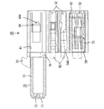
本発明の実施形態1を図1ないし図17によって説明する。本発明のコネクタは、互いに嵌合可能な雌雄一対のコネクタ10、50からなる。雄側コネクタ10は、雄側ハウジング11、雄型端子金具12、雄側ダミーコネクタ本体30、雄側ハウジング部13、レバー14及びムービングプレート15を備えている。雌側コネクタ50は、雌側ハウジング51、雌型端子金具52、雌側ダミーコネクタ本体70及び雌側ハウジング部53を備えている。なお、以下の説明において前後方向については両コネクタ10、50の互いの嵌合面側を前方とする。
<Embodiment 1>
A first embodiment of the present invention will be described with reference to FIGS. The connector of the present invention comprises a pair of male and female connectors 10 and 50 that can be fitted to each other. The male connector 10 includes a male housing 11, a male terminal fitting 12, a male dummy connector body 30, a male housing part 13, a lever 14, and a moving plate 15. The female connector 50 includes a female housing 51, a female terminal fitting 52, a female dummy connector main body 70, and a female housing portion 53. In the following description, in the front-rear direction, the mating surfaces of the connectors 10 and 50 are the front.

雄側ハウジング11は合成樹脂製であって、図1に示すように、雄型端子金具12を収容可能な角ブロック状の端子収容部16と、端子収容部16の前端周縁から前方へ突出する角筒状のフード部17とを備えている。雄側ハウジング11の下面には図示しない外部ブラケットに取り付けるための取付片18が後方へ突出して設けられている。雄側ハウジング11には外側から門型のレバー14が跨嵌して装着されている。レバー14は幅方向に延びる操作部14Aと操作部14Aの両端から平行に突出する一対のアーム部14Bとからなり、図3に示すように、両アーム部14Bには軸受孔14Cが設けられている。雄側ハウジング11には、フード部17における端子収容部16寄りの両側面に、両アーム部14Bの軸受孔14Cに挿着される支軸19が突設されている。レバー14は支軸19を中心として初期位置と嵌合位置とに回動可能とされている。操作部14Aには撓み可能なロック部20が設けられており、レバー14が嵌合位置に達すると、ロック部20が相手の雌側ハウジング51に設けられたロック受部55(後述する)を弾性的に係止して、両ハウジング11、51が嵌合状態にロックされるようになっている。   As shown in FIG. 1, the male housing 11 is made of a synthetic resin, and protrudes forward from a rectangular block-shaped terminal accommodating portion 16 that can accommodate the male terminal fitting 12 and a front end periphery of the terminal accommodating portion 16. A square tube-shaped hood portion 17 is provided. An attachment piece 18 for attaching to an external bracket (not shown) is provided on the lower surface of the male housing 11 so as to protrude rearward. The male housing 11 is fitted with a portal lever 14 straddling from the outside. The lever 14 includes an operating portion 14A extending in the width direction and a pair of arm portions 14B protruding in parallel from both ends of the operating portion 14A. As shown in FIG. 3, both arm portions 14B are provided with bearing holes 14C. Yes. The male housing 11 is provided with support shafts 19 protruding from both side surfaces of the hood portion 17 near the terminal housing portion 16 and inserted into the bearing holes 14C of both arm portions 14B. The lever 14 is rotatable about the support shaft 19 between an initial position and a fitting position. The operation portion 14A is provided with a lock portion 20 that can be bent. When the lever 14 reaches the fitting position, the lock portion 20 is provided with a lock receiving portion 55 (described later) provided on the counterpart female housing 51. The housings 11 and 51 are locked in an engaged state by being elastically locked.

両アーム部14Bの内面には、所定形状に延びて入り口が両アーム部14Bの周縁に開口するカム溝14Eが凹設されている。初期位置では、カム溝14Eの入り口が前方を向いて開放される。フード部17の両側壁には、図2に示すように、前後方向に延びてフード部17の前端に開口する導入溝21が初期位置においてカム溝14Eの入り口と連通するように形成されている。また、両アーム部14Bには、弾性係止片14Fが切り欠いて形成されている。フード部17の両側壁には弾性係止片14Fを受ける係止受溝22が導入溝21と平行に延びてフード部17の前端に開口して形成されており、初期位置では、弾性係止片14Fが係止受溝22の溝縁に弾性的に掛け止められて、レバー14の嵌合位置への回動操作が規制されるようになっている。   On the inner surfaces of both arm portions 14B, cam grooves 14E extending in a predetermined shape and having openings at the peripheral edges of both arm portions 14B are recessed. In the initial position, the entrance of the cam groove 14E is opened facing forward. As shown in FIG. 2, introduction grooves 21 that extend in the front-rear direction and open at the front end of the hood portion 17 are formed on both side walls of the hood portion 17 so as to communicate with the entrance of the cam groove 14 </ b> E at the initial position. . Further, the elastic locking pieces 14F are cut out and formed on both arm portions 14B. Lock receiving grooves 22 for receiving the elastic locking pieces 14F are formed on both side walls of the hood portion 17 so as to extend in parallel with the introduction grooves 21 and open at the front end of the hood portion 17. The piece 14F is elastically hooked on the groove edge of the latch receiving groove 22 so that the turning operation of the lever 14 to the fitting position is restricted.

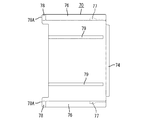
フード部17内には、ムービングプレート15が嵌合して装着されている。ムービングプレート15は端子収容部16の前面と平行して同前面を覆うように配置されるプレート本体15Aを有している。プレート本体15Aには雄型端子金具12のタブ12Aを位置決め状態で受ける位置決め孔15Bが貫通して形成されている。かかるムービングプレート15は、プレート本体15Aが端子収容部16の前面から離れて位置して、タブ12Aの先端部が位置決め孔15Bを貫通する前進位置と、プレート本体15Aが端子収容部16の前面の近くに位置して、タブ12Aの根元部が位置決め孔15Bを貫通する後退位置とに移動可能とされている。前進位置では、タブ12Aの先端部が位置決め孔15Bを貫通することにより、タブ12Aが保護状態に置かれるようになっている。   A moving plate 15 is fitted and mounted in the hood portion 17. The moving plate 15 has a plate main body 15 </ b> A arranged so as to cover the front surface of the terminal accommodating portion 16 in parallel with the front surface. The plate body 15A is formed with a positioning hole 15B that receives the tab 12A of the male terminal fitting 12 in a positioned state. The moving plate 15 has a plate main body 15A positioned away from the front surface of the terminal accommodating portion 16 and a forward position where the tip of the tab 12A penetrates the positioning hole 15B, and the plate main body 15A is located on the front surface of the terminal accommodating portion 16. It is possible to move to the retracted position where the base portion of the tab 12A penetrates the positioning hole 15B. In the advanced position, the tab 12A is placed in a protected state by the tip of the tab 12A passing through the positioning hole 15B.

端子収容部16にはキャビティ16Aが前後に貫通して形成されている。キャビティ16Aは端子収容部16の高さ方向の中段において上下2段に分かれて配置され、ここに後方から大型の雄型端子金具12が挿入可能とされている。このうち、上段の雄型端子金具12は、下段の雄型端子金具12よりも大型とされ、相互の挿入姿勢を軸周りに略90度ずらしつつキャビティ16A内に挿入されている。キャビティ16Aの内壁には、雄型端子金具12のキャビティ16Aからの抜け止めをなすランス16Bが撓み可能に設けられている。   A cavity 16A is formed in the terminal accommodating portion 16 so as to penetrate in the front-rear direction. The cavity 16A is divided into two upper and lower stages in the middle of the height direction of the terminal accommodating portion 16, and a large male terminal fitting 12 can be inserted into the cavity 16A from the rear. Among these, the upper male terminal fitting 12 is larger than the lower male terminal fitting 12, and is inserted into the cavity 16A while shifting the mutual insertion posture about 90 degrees around the axis. On the inner wall of the cavity 16A, a lance 16B that prevents the male terminal fitting 12 from coming off from the cavity 16A is flexibly provided.

端子収容部16の高さ方向の下段には第1収容部23が前後に貫通して形成されている。第1収容部23には扁平な角ブロック状の雄側ハウジング部13が収容されており、第1収容部23の後端開口が雄側ハウジング部13を挿入可能な挿入口とされている。雄側ハウジング部13にはキャビティ13Aが前後に貫通して形成されている。キャビティ13Aは上下2段に分かれて配置され、ここに後方から小型の雄型端子金具12が挿入可能とされている。キャビティ13Aの内壁には、ランス13Bが撓み可能に設けられている。また、雄側ハウジング部13の前端部にはフロントホルダ13Dが装着され、雄側ハウジング部13の中間部にはリテーナ13Eが装着されている。雄側ハウジング11の後端面は、図3に示すように、概ね略垂直に切り立って配置され、その中段から下段にかけて大型及び小型の各雄型端子金具12に接続された複数の電線W1が引き出される電線引き出し面24とされている。   A first housing part 23 is formed in the lower part in the height direction of the terminal housing part 16 so as to penetrate therethrough. A flat rectangular block-shaped male housing part 13 is accommodated in the first accommodating part 23, and a rear end opening of the first accommodating part 23 is an insertion port into which the male housing part 13 can be inserted. The male housing part 13 is formed with a cavity 13A penetrating in the front-rear direction. The cavity 13A is arranged in two upper and lower stages, and a small male terminal fitting 12 can be inserted into the cavity 13A from behind. A lance 13B is provided on the inner wall of the cavity 13A so as to be able to bend. A front holder 13 </ b> D is attached to the front end portion of the male housing portion 13, and a retainer 13 </ b> E is attached to an intermediate portion of the male housing portion 13. As shown in FIG. 3, the rear end surface of the male housing 11 is arranged substantially vertically so that a plurality of electric wires W1 connected to the large and small male terminal fittings 12 are drawn out from the middle stage to the lower stage. It is set as the electric wire drawer | drawing-out surface 24.

端子収容部16の高さ方向の上段には、第1収容部23とほぼ同形状の第2収容部25が前後に貫通して形成されている。第2収容部25には、第1収容部23と同様、雄側ハウジング部13が収容可能とされているが、本実施形態ではここが空きの部分とされていて、回路構成に関与しない雄側ダミーコネクタ本体30が収容されている。第2収容部25の後端開口は雄側ダミーコネクタ本体30を挿入可能な挿入口とされている。   In the upper stage of the terminal accommodating part 16 in the height direction, a second accommodating part 25 having substantially the same shape as the first accommodating part 23 is formed penetrating in the front-rear direction. Although the male housing part 13 can be accommodated in the second accommodating part 25 in the same manner as the first accommodating part 23, this is an empty part in the present embodiment and is not involved in the circuit configuration. The side dummy connector main body 30 is accommodated. The rear end opening of the second housing portion 25 is an insertion port into which the male dummy connector main body 30 can be inserted.

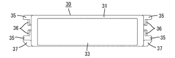
雄側ダミーコネクタ本体30は合成樹脂製であって、全体としてキャップ状をなし、幅方向に延出して第2収容部25の前端開口を覆う前壁31と、前壁31の周縁から全周に亘って後方へ延出する扁平角筒状の周壁32とを有している。図6に示すように、前壁31の前面は閉止面とされており、前壁31の中央部は一段前方へ突き出る形態の膨出部33とされている。膨出部33は後退位置におけるムービングプレート15のプレート本体15Aに凹み形成された嵌合部15G内に嵌合可能とされている。また、雄側ダミーコネクタ本体30の内部には、図4に示すように、周壁32の上下の内面同士をつなげる縦壁34が幅方向に間隔をあけて複数架設されている。   The male dummy connector main body 30 is made of a synthetic resin, has a cap shape as a whole, extends in the width direction and covers the front end opening of the second housing portion 25, and the entire periphery from the periphery of the front wall 31. And a peripheral wall 32 having a flat rectangular tube shape extending rearward. As shown in FIG. 6, the front surface of the front wall 31 is a closing surface, and the central portion of the front wall 31 is a bulging portion 33 that protrudes forward one step. The bulging portion 33 can be fitted into a fitting portion 15G formed as a recess in the plate body 15A of the moving plate 15 in the retracted position. Further, as shown in FIG. 4, a plurality of vertical walls 34 that connect the upper and lower inner surfaces of the peripheral wall 32 are provided in the male dummy connector main body 30 at intervals in the width direction.

周壁32の両側外面には、図8に示すように、雄側ダミーコネクタ本体30の第2収容部25への挿入動作を案内するための案内突部35が前後方向に延出して形成されている。案内突部35は、前後方向に細長いリブ状をなし、上下で対をなしつつ互いに平行に配置されている。両案内突部35の前端側における相対向する内面には、上下一対の係止部36が突設されており、両係止部36間に隙間が保有されている。一方、第2収容部25の内壁の両側面には、図5に示すように、幅方向に撓み可能な係止受部26が突設されており、雄側ダミーコネクタ本体30が収容部内に正規深さで挿入されると、係止受部26に係止部36が弾性的に係止されて、雄側ダミーコネクタ本体30の第2収容部25からの抜け止めがなされるようになっている。係止受部26の高さ方向の中央部には規制突起26Aが形成されており、規制突起26Aが両係止部36間の隙間に進入することで、両係止部36の高さ方向の遊動が規制されて、両者の係止状態の安定性が確保されるようになっている。また、第2収容部25内における係止受部26を挟んだ両側は、案内突部35が摺動可能な上下一対の案内溝27とされている。なお、これら係止受部26及び案内溝27の構造は、第1収容部23にも同様に形成されている。また、ムービングプレート15のプレート本体15Aには、図2に示すように、係止受部26と対向する位置に窓孔15Eが開設されており、窓孔15Eを通して係止受部26による係止状態を解除可能とされている。   As shown in FIG. 8, guide protrusions 35 for guiding the insertion operation of the male dummy connector main body 30 into the second housing portion 25 are formed on the outer surfaces of both sides of the peripheral wall 32 so as to extend in the front-rear direction. Yes. The guide protrusions 35 are in the form of ribs that are elongated in the front-rear direction, and are arranged parallel to each other while forming a pair in the upper and lower directions. A pair of upper and lower locking portions 36 protrude from the opposing inner surfaces on the front end side of both guide protrusions 35, and a gap is held between the both locking portions 36. On the other hand, on both side surfaces of the inner wall of the second housing portion 25, as shown in FIG. 5, locking receiving portions 26 that can be bent in the width direction are projected, and the male dummy connector main body 30 is placed in the housing portion. When inserted at a normal depth, the locking portion 36 is elastically locked to the locking receiving portion 26, and the male dummy connector body 30 is prevented from coming off from the second housing portion 25. ing. A restricting projection 26A is formed at the center of the latch receiving portion 26 in the height direction, and the restricting projection 26A enters the gap between the catch portions 36, whereby the height direction of the catch portions 36 is increased. Is controlled to ensure the stability of the locked state of both. Further, on both sides of the second receiving portion 25 with the latch receiving portion 26 sandwiched, a pair of upper and lower guide grooves 27 on which the guide projection 35 can slide is formed. Note that the structures of the latch receiving portion 26 and the guide groove 27 are formed in the first housing portion 23 in the same manner. Further, as shown in FIG. 2, a window hole 15E is formed in the plate main body 15A of the moving plate 15 at a position facing the locking receiving portion 26, and the locking receiving portion 26 locks through the window hole 15E. The state can be released.

また、周壁32の両側外面の後端部には、図6ないし図8に示すように、板状をなす一対の突部37が側方及び後方に張り出して設けられている。突部37は、下側の案内突部35の後端に一体に連なりながら雄側ダミーコネクタ本体30の後端より後方へいったん突出したあと案内突部35をその延び方向と直交する下向きに延長させた形態をなしている。詳細には突部37は、その側方への突出端が案内突部35の突出端と一致するとともに、その下端が周壁32の下側外面に一致し、かつ下端と突出端との間が斜め方向に角落ちされたテーパ縁によってつながる形態をなしている。突部37の後端面は、前端面とともに略垂直に切り立って配置され、指押しされるに適当な大きさの平面状をなす平面部37Aとされている。   Further, as shown in FIGS. 6 to 8, a pair of projections 37 having a plate shape are provided on the rear end portions of both outer surfaces of the peripheral wall 32 so as to protrude sideways and rearward. The protrusion 37 once extends backward from the rear end of the male dummy connector body 30 while being integrally connected to the rear end of the lower guide protrusion 35, and then extends the guide protrusion 35 downward perpendicular to the extending direction. It is in the form of Specifically, the protrusion 37 has a side protruding end that coincides with the protruding end of the guide protrusion 35, a lower end that matches the lower outer surface of the peripheral wall 32, and a gap between the lower end and the protruding end. It is connected by a taper edge that is angled in an oblique direction. The rear end surface of the projecting portion 37 is arranged so as to stand substantially vertically together with the front end surface, and is a flat portion 37A having a flat shape of an appropriate size for finger pressing.

ここで、雄側ダミーコネクタ本体30が正逆(前後)反転した姿勢をとって第2収容部25に挿入されようとすると、突部37が第2収容部25の挿入口の口縁と干渉して、雄側ダミーコネクタ本体30の挿入動作が規制される。一方、雄側ダミーコネクタ本体30が正規の姿勢をとって第2収容部25に挿入されると、雄側ダミーコネクタ本体30のうちの突部37を除く部分が第2収容部25に正規深さで挿入されるとともに、突部37が第2収容部25に挿入されることなく挿入口より外側に露出して配置されるようになっている。   Here, when the male dummy connector main body 30 is inserted in the second housing part 25 in a forward / reverse (front / rear) inverted posture, the projection 37 interferes with the rim of the insertion port of the second housing part 25. Thus, the insertion operation of the male dummy connector main body 30 is restricted. On the other hand, when the male side dummy connector body 30 is inserted into the second housing part 25 in a normal posture, the portion of the male side dummy connector body 30 excluding the protrusions 37 has a normal depth in the second housing part 25. In addition, the protrusion 37 is arranged so as to be exposed to the outside of the insertion port without being inserted into the second accommodating portion 25.

続いて雌側ハウジング51について説明すると、雌側ハウジング51は同じく合成樹脂製であって、図9に示すように、角ブロック状をなすハウジング本体54を備えて構成されている。ハウジング本体54の上面の後端には後方へ向けて突出するロック受部55が設けられている。両ハウジング11、51が正規嵌合されると、ハウジング本体54はロック受部55を除いてフード部17内に嵌合され、さらにロック受部55は嵌合位置に達したレバー14のロック部20に弾性係止されるようになっている。   Next, the female housing 51 will be described. The female housing 51 is also made of a synthetic resin, and includes a housing main body 54 having a rectangular block shape as shown in FIG. A lock receiving portion 55 is provided at the rear end of the upper surface of the housing main body 54 so as to protrude rearward. When both the housings 11 and 51 are properly fitted, the housing main body 54 is fitted into the hood portion 17 except for the lock receiving portion 55, and the lock receiving portion 55 reaches the fitting position. 20 is elastically locked.

ハウジング本体54の両側面には、図11に示すように、高さ方向の中段に、高さ方向の上段及び下段に比べて幅寸法を狭めた形態の括れ部56が設けられている。括れ部56の底面には一対のカムフォロア57が側方に突出して形成されている。カムフォロア57は、両ハウジング11、51の嵌合過程で導入溝21を介してカム溝14Eの入り口に進入し、レバー14の回動に伴ってカム溝14E内を移動してカム作用を発揮し、両ハウジング11、51を低操作力で嵌合する役割をはたす。なお、カムフォロア57はムービングプレート15とも係合可能とされ、レバー14の回動操作に追従してムービングプレート15が後退位置と前進位置とに移動可能とされている。   As shown in FIG. 11, a constricted portion 56 having a narrower width than the upper and lower stages in the height direction is provided on both side surfaces of the housing main body 54 as shown in FIG. A pair of cam followers 57 are formed on the bottom surface of the constricted portion 56 so as to protrude laterally. The cam follower 57 enters the entrance of the cam groove 14E through the introduction groove 21 during the fitting process of the housings 11 and 51, and moves in the cam groove 14E as the lever 14 rotates to exert a cam action. The housings 11 and 51 are engaged with each other with a low operating force. The cam follower 57 can also be engaged with the moving plate 15, and the moving plate 15 can be moved between the retracted position and the advanced position following the turning operation of the lever 14.

ハウジング本体54の両側面には、高さ方向の下段に、両ハウジング11、51の嵌合過程でレバー14の弾性係止片14Fと干渉して弾性係止片14Fと係止受溝22との係止状態を解除する解除部58が突設されている。解除部58は、図10に示すように、前後方向に細長く延びるリブ状の形態をなしている。
ハウジング本体54の高さ方向の中段にはキャビティ54Aが前後に貫通して形成されている。キャビティ54Aには後方から大型の雌型端子金具52が挿入可能とされている。
On both side surfaces of the housing main body 54, the elastic locking pieces 14F and the locking receiving grooves 22 interfere with the elastic locking pieces 14F of the lever 14 during the fitting process of the housings 11 and 51 on the lower side in the height direction. A release portion 58 that releases the locked state is provided. As shown in FIG. 10, the release portion 58 has a rib shape extending in the longitudinal direction.
A cavity 54A is formed in the middle of the housing body 54 in the height direction so as to penetrate therethrough. A large female terminal fitting 52 can be inserted into the cavity 54A from the rear.

また、ハウジング本体54の高さ方向の下段には第3収容部59が前後に貫通して形成されている。第3収容部59には雌側ハウジング部53が収容可能とされており、第3収容部59の後端開口が雌側ハウジング部53を挿入可能な挿入口とされている。雌側ハウジング部53には上下2段のキャビティ53Aが前後に貫通して形成され、各キャビティ53Aに後方から小型の雌型端子金具52が挿入可能とされている。ハウジング本体54の後端面は、概ね略垂直に切り立って配置され、その中段から下段にかけて大型及び小型の雌型端子金具52に接続された複数の電線W2が引き出される電線引き出し面60とされている。   A third housing part 59 is formed in the lower part of the housing main body 54 in the height direction so as to penetrate in the front-rear direction. The third housing part 59 can accommodate the female housing part 53, and the rear end opening of the third housing part 59 is an insertion port into which the female housing part 53 can be inserted. The female housing portion 53 is formed with two upper and lower cavities 53A penetrating in the front-rear direction, and a small female terminal fitting 52 can be inserted into each cavity 53A from the rear. The rear end surface of the housing main body 54 is arranged substantially vertically so as to be a wire drawing surface 60 from which a plurality of wires W2 connected to the large and small female terminal fittings 52 are drawn from the middle stage to the lower stage. .

ハウジング本体54の高さ方向の上段には、第3収容部59とほぼ同形状の第4収容部61が前後に貫通して形成されている。本実施形態においては、第4収容部61に雌側ダミーコネクタ本体70が収容可能とされ、第4収容部61の後端開口が雌側ダミーコネクタ本体70を挿入可能な挿入口とされている。第4収容部61の内壁及び第3収容部59の内壁には、それぞれ雌側ダミーコネクタ本体70及び雌側ハウジング部53の前止まりをなす段部62が設けられている。段部62内には、正規挿入された雌側ダミーコネクタ本体70の膨出部74が嵌合可能とされている。その他、ハウジング本体54の構造は端子収容部16の構造と実質的に同じであり、雌側ハウジング部53の構造も雄側ハウジング部13の構造と実質的に同じである。特に、第3収容部59及び第4収容部61には、図14に示すように、上記第1収容部23及び第2収容部25における係止受部26及び規制突起26Aと同形状をなす係止突部66及び規制突起66Aが形成されている。   In the upper part of the housing main body 54 in the height direction, a fourth housing portion 61 having substantially the same shape as the third housing portion 59 is formed to penetrate in the front-rear direction. In the present embodiment, the female dummy connector main body 70 can be accommodated in the fourth accommodating portion 61, and the rear end opening of the fourth accommodating portion 61 is an insertion port into which the female dummy connector main body 70 can be inserted. . On the inner wall of the fourth housing part 61 and the inner wall of the third housing part 59, a step part 62 is provided that forms a front stop of the female side dummy connector main body 70 and the female side housing part 53, respectively. In the stepped portion 62, a bulging portion 74 of the female-side dummy connector main body 70 that is normally inserted can be fitted. In addition, the structure of the housing body 54 is substantially the same as the structure of the terminal accommodating portion 16, and the structure of the female housing portion 53 is substantially the same as the structure of the male housing portion 13. In particular, the third housing portion 59 and the fourth housing portion 61 have the same shape as the locking receiving portion 26 and the restricting protrusion 26A in the first housing portion 23 and the second housing portion 25, as shown in FIG. A locking projection 66 and a regulation projection 66A are formed.

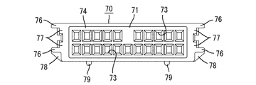
雌側ダミーコネクタ本体70は、雄側ダミーコネクタ本体30と同様、合成樹脂製であって全体としてキャップ状をなし、幅方向に延出して第4収容部61の前端開口を覆う前壁71と、前壁71の周縁から全周に亘って後方へ延出する周壁72とを有している。前壁71には、図15に示すように、タブ挿入口73が開口して形成されており、仮に、第2収容部25に雄側ハウジング部13が収容された場合に、雄型端子金具12のタブ12Aがタブ挿入口73に挿入されて逃されるようになっている。その他、雌側ダミーコネクタ本体70の構造は、雄側ダミーコネクタ本体30の構造と実質的に同じであり、雄側ダミーコネクタ本体30と同形状をなす、膨出部74、縦壁75、案内突部76、係止部77、突部78、及び突部78の後端面を構成する平面部78Aを有している。   The female side dummy connector main body 70 is made of a synthetic resin and has a cap shape as a whole, like the male side dummy connector main body 30, and extends in the width direction to cover the front end opening of the fourth housing portion 61. And a peripheral wall 72 extending rearward from the peripheral edge of the front wall 71 over the entire periphery. As shown in FIG. 15, the front wall 71 is formed with a tab insertion opening 73 opened. If the male housing part 13 is accommodated in the second accommodating part 25, the male terminal fitting is provided. Twelve tabs 12 </ b> A are inserted into the tab insertion slot 73 and escaped. In addition, the structure of the female dummy connector main body 70 is substantially the same as the structure of the male dummy connector main body 30 and has the same shape as the male dummy connector main body 30. The bulging portion 74, the vertical wall 75, the guide The projection 76, the locking portion 77, the projection 78, and the flat portion 78 </ b> A constituting the rear end surface of the projection 78 are provided.

もっとも、雌側ダミーコネクタ本体70には案内突部76とは別に案内リブ79が設けられ、第4収容部61には案内リブ79を受ける案内リブ受部68が設けられており、この点は雄側ダミーコネクタ本体30及び第2収容部25とは異なっている。案内リブ79は周壁72の下側外面において幅方向に対をなしつつ前後方向に延出して形成され、案内リブ受部68は第4収容部61の内壁の下面において同じく幅方向に対をなしつつ前後方向に延出して形成されている。   However, the female dummy connector main body 70 is provided with a guide rib 79 in addition to the guide protrusion 76, and the fourth housing portion 61 is provided with a guide rib receiving portion 68 for receiving the guide rib 79. The male side dummy connector main body 30 and the second accommodating portion 25 are different. The guide rib 79 is formed to extend in the front-rear direction while forming a pair in the width direction on the lower outer surface of the peripheral wall 72, and the guide rib receiving portion 68 is also paired in the width direction on the lower surface of the inner wall of the fourth housing portion 61. However, it extends in the front-rear direction.

次に本実施形態の作用を説明する。
両ハウジング11、51の嵌合に先立ち、まず雄側ハウジング11のキャビティ16Aに大型の雄型端子金具12を挿入するとともに、雄側ハウジング11の第1収容部23に小型の雄型端子金具12を収容させた雄側ハウジング部13を挿入し、かつ雄側ハウジング11の第2収容部25に雄側ダミーコネクタ本体30を挿入する。また、雌側ハウジング51のキャビティ54Aに大型の雌型端子金具52を挿入するとともに、雌側ハウジング51の第3収容部59に小型の雌型端子金具52を収容させた雌側ハウジング部53を挿入し、かつ雌側ハウジング51の第4収容部61に雌側ダミーコネクタ本体70を挿入する。
Next, the operation of this embodiment will be described.
Prior to fitting the two housings 11 and 51, first, the large male terminal fitting 12 is inserted into the cavity 16 </ b> A of the male housing 11, and the small male terminal fitting 12 is inserted into the first housing portion 23 of the male housing 11. Is inserted, and the male dummy connector main body 30 is inserted into the second housing part 25 of the male housing 11. Further, a large female terminal fitting 52 is inserted into the cavity 54A of the female housing 51, and a female housing portion 53 in which the small female terminal fitting 52 is housed in the third housing portion 59 of the female housing 51 is provided. The female dummy connector main body 70 is inserted into the fourth accommodating portion 61 of the female housing 51.

雄側ダミーコネクタ本体30の第2収容部25への挿入にあたり、雄側ダミーコネクタ本体30が正規の挿入姿勢をとっていれば、雄側ダミーコネクタ本体30は、膨出部33を先頭にして挿入口から第2収容部25内に進入し、案内突部35が案内溝27内を摺動することによって案内されつつ正規の挿入位置へと円滑に至る。正規の挿入位置では、係止部36が係止受部26を弾性係止することによって雄側ダミーコネクタ本体30の後方への抜け止めがなされる。このとき、雄側ハウジング11の電線引き出し面24には、図1及び図4に示すように、雄型端子金具12に接続された電線W1とともに雄側ダミーコネクタ本体30の突部37が挿入口より外側に突出状態で配置されることとなる。したがって、この状態を視認または触認することにより、雄側ダミーコネクタ本体30が正規の挿入位置に至ったことを知ることができる。また、突部37が第2収容部25の挿入口の口縁に突き当たることにより、雄側ダミーコネクタ本体30の前止まりにもなる。なお、雌側ダミーコネクタ本体70の第4収容部61への挿入動作及び装着態様も雄側ダミーコネクタ本体30の場合とほぼ同様である。また、雌雄の両ダミーコネクタ本体30、70の挿入動作は、平面部37A、78Aに指を宛がいながら突部37、78を前方へ押し込むことによって円滑に行うことができる。   When inserting the male dummy connector body 30 into the second housing portion 25, if the male dummy connector body 30 is in a proper insertion posture, the male dummy connector body 30 starts from the bulging portion 33. It enters into the 2nd accommodating part 25 from an insertion port, and it guides smoothly by the guide protrusion part 35 sliding by the inside of the guide groove 27, and reaches a regular insertion position. At the regular insertion position, the locking portion 36 elastically locks the locking receiving portion 26 to prevent the male dummy connector main body 30 from coming off backward. At this time, as shown in FIGS. 1 and 4, a protrusion 37 of the male dummy connector main body 30 together with the electric wire W <b> 1 connected to the male terminal fitting 12 is inserted into the electric wire drawing surface 24 of the male housing 11. It will be arranged in a protruding state on the outer side. Therefore, it is possible to know that the male dummy connector main body 30 has reached the proper insertion position by visually checking or tapping this state. Further, when the protrusion 37 abuts against the edge of the insertion opening of the second housing portion 25, the male dummy connector main body 30 is also stopped at the front. The inserting operation and mounting manner of the female dummy connector main body 70 into the fourth accommodating portion 61 are also substantially the same as those of the male dummy connector main body 30. The male and female dummy connector bodies 30 and 70 can be inserted smoothly by pushing the protrusions 37 and 78 forward while placing a finger on the flat surfaces 37A and 78A.

続いて、レバー14を初期位置にセットした状態で両ハウジング11、51を浅く嵌合させる。すると、カムフォロア57がカム溝14Eの入り口に進入し、解除部58によって弾性係止片14Fによる係止状態が解除されて、レバー14の嵌合位置への回動操作が許容される。そこでレバー14を嵌合位置側へ向けて図示反時計周りに回動させると、カムフォロア57がカム溝14Eに沿って移動するとともに、ムービングプレート15が後退位置へ向けて移動し、かつ雄型端子金具12のタブ12Aが雌型端子金具52内に進入する。両ハウジング11、51が正規嵌合されると、レバー14のロック部20がロック受部55を弾性係止してレバー14の回動操作が規制されるとともに両ハウジング11、51が離脱規制状態に保持され、かつ雌雄の両端子金具12、52が導通可能に接続される。このとき、雌雄の両ダミーコネクタ本体30、70はムービングプレート15のプレート本体15Aを介して互いに対面位置することとなる。   Subsequently, the housings 11 and 51 are shallowly fitted with the lever 14 set to the initial position. Then, the cam follower 57 enters the entrance of the cam groove 14E, and the release state 58 releases the locking state by the elastic locking piece 14F, and the lever 14 is allowed to rotate to the fitting position. Therefore, when the lever 14 is rotated counterclockwise in the figure toward the mating position, the cam follower 57 moves along the cam groove 14E, the moving plate 15 moves toward the retracted position, and the male terminal The tab 12A of the metal fitting 12 enters the female terminal metal fitting 52. When the two housings 11 and 51 are properly fitted, the lock portion 20 of the lever 14 elastically locks the lock receiving portion 55 to restrict the rotation operation of the lever 14 and the two housings 11 and 51 are in the disengagement restricted state. The male and female terminal fittings 12 and 52 are connected so as to be conductive. At this time, both the male and female dummy connector bodies 30 and 70 face each other via the plate body 15A of the moving plate 15.

ところで、雄側ダミーコネクタ本体30の第2収容部25への挿入にあたり、雄側ダミーコネクタ本体30が正逆(前後)反転した挿入姿勢をとっていると、図5に示すように、突部37が挿入口の口縁における下側2角に突き当たり、雄側ダミーコネクタ本体30は第2収容部25に全く挿入されることはない。雌側ダミーコネクタ本体70についても同様であり、雌側ダミーコネクタ本体70が正逆(前後)反転した挿入姿勢をとっていると、図14に示すように、突部78が第4収容部61の挿入口の口縁における下側2角に突き当たり、雌側ダミーコネクタ本体70は第4収容部61に全く挿入されることはない。   By the way, when the male dummy connector main body 30 is inserted into the second housing portion 25, when the male dummy connector main body 30 is in an insertion posture in which the male side dummy connector main body 30 is reversed forward and backward (front and rear), as shown in FIG. 37 hits the lower two corners at the edge of the insertion slot, and the male dummy connector main body 30 is not inserted into the second housing portion 25 at all. The same applies to the female-side dummy connector main body 70. When the female-side dummy connector main body 70 has an insertion posture in which the female-side dummy connector main body 70 is reversed forward and backward (front and rear), as shown in FIG. The female-side dummy connector main body 70 is not inserted into the fourth accommodating portion 61 at all by hitting the lower two corners at the edge of the insertion opening.

以上説明したように本実施形態によれば、ダミーコネクタ本体30、70が正規の挿入姿勢をとっていない場合に、突部37、78が収容部(第2収容部25又は第4収容部61)の挿入口の口縁と干渉してその挿入動作が規制されるから、ダミーコネクタ本体30、70(ダミーコネクタ)の誤挿入が防止される。この場合、収容部(第2収容部25又は第4収容部61)内に突部37、78が進入しないため、収容部(第2収容部25又は第4収容部61)に突部37、78の逃がし構造を設ける必要がなく、構成の簡素化を図れるとともに、収容部(第2収容部25又は第4収容部61)の大型化が回避される。また、ダミーコネクタ本体30、70が正規の姿勢をとっている場合には、突部37、78が挿入口より外側に突出して配置されるから、その状態を視認又は触認することにより、ダミーコネクタ本体30、70が収容部(第2収容部25又は第4収容部61)に正規挿入されていることがわかり、ダミーコネクタ本体30、70(ダミーコネクタ)の挿入のし忘れが防止される。   As described above, according to the present embodiment, when the dummy connector main bodies 30 and 70 are not in the normal insertion posture, the protrusions 37 and 78 are provided with the accommodating portions (the second accommodating portion 25 or the fourth accommodating portion 61). ) Is interfered with the rim of the insertion port and its insertion operation is restricted, so that erroneous insertion of the dummy connector bodies 30 and 70 (dummy connector) is prevented. In this case, since the protrusions 37 and 78 do not enter the storage part (the second storage part 25 or the fourth storage part 61), the protrusion 37 and the storage part (the second storage part 25 or the fourth storage part 61). There is no need to provide 78 escape structures, the configuration can be simplified, and an increase in the size of the accommodating portion (the second accommodating portion 25 or the fourth accommodating portion 61) is avoided. Further, when the dummy connector main bodies 30 and 70 are in a regular posture, the protrusions 37 and 78 are arranged to protrude outward from the insertion port. It can be seen that the connector main bodies 30 and 70 are properly inserted into the accommodating portion (the second accommodating portion 25 or the fourth accommodating portion 61), and forgetting to insert the dummy connector main bodies 30 and 70 (dummy connector) is prevented. .

また、収容部(第2収容部25又は第4収容部61)の挿入口が雌雄の両ハウジング11、51における電線引き出し面24、60と同じ側に配置されているため、挿入口の口縁から突出する突部37、78と並んで電線W1、W2が位置することとなり、電線W1、W2の並び方向のデッドスペースが有効に活用される。また、電線W1、W2によって突部37、78の突出状態のみが際立つことはなく、突部37、78が他の部品と干渉する等といった不具合も起こり難い。   Moreover, since the insertion port of the accommodating part (the second accommodating part 25 or the fourth accommodating part 61) is arranged on the same side as the wire drawing surfaces 24, 60 in both the male and female housings 11, 51, the rim of the insertion opening The electric wires W1 and W2 are positioned side by side with the projecting portions 37 and 78 protruding from the cable, and the dead space in the arrangement direction of the electric wires W1 and W2 is effectively utilized. Further, only the protruding state of the protrusions 37 and 78 is not conspicuous by the electric wires W1 and W2, and problems such as the protrusions 37 and 78 interfering with other parts hardly occur.

さらに、突部37、78の後端面が指押し可能な平坦領域をもった平面部37A、78Aとされているため、平面部37A、78Aに指を宛がいながらダミーコネクタ本体30、70を収容部(第2収容部25又は第4収容部61)に挿入することができ、作業性が良好になる。また、突部37、78以外の部位に指押し用の平面部37A、78Aを設けるよりも構成が簡素化される。   Furthermore, since the rear end surfaces of the projections 37 and 78 are flat portions 37A and 78A having flat areas where the fingers can be pushed, the dummy connector main bodies 30 and 70 are accommodated while the fingers are placed on the flat portions 37A and 78A. Can be inserted into the portion (the second accommodating portion 25 or the fourth accommodating portion 61), and the workability is improved. Further, the configuration is simplified as compared with the case where the flat portions 37A and 78A for finger pressing are provided at portions other than the protrusions 37 and 78.

さらにまた、突部37、78が案内突部35、76の後端に一体に連なり、案内突部35、76によって突部37、78が補強されるから、異物との干渉等に起因して突部37、78が折損される事態が回避される。   Furthermore, since the protrusions 37 and 78 are integrally connected to the rear ends of the guide protrusions 35 and 76, and the protrusions 37 and 78 are reinforced by the guide protrusions 35 and 76, the protrusions 37 and 78 are caused by interference with a foreign object or the like. The situation where the protrusions 37 and 78 are broken is avoided.

<他の実施形態>
本発明は上記記述及び図面によって説明した実施形態に限定されるものではなく、例えば次のような実施形態も本発明の技術的範囲に含まれる。
(1)ダミーコネクタ本体を収容可能な収容部は、端子金具を収容しない単なるケースに形成されていてもよい。
(2)第1収容部又は第3収容部に、ハウジング部に代わってダミーコネクタ本体が挿入されてもよい。
(3)案内突部と突部とは互いに切り離されていてもよい。
<Other embodiments>
The present invention is not limited to the embodiments described with reference to the above description and drawings. For example, the following embodiments are also included in the technical scope of the present invention.
(1) The accommodating portion that can accommodate the dummy connector main body may be formed in a simple case that does not accommodate the terminal fitting.
(2) A dummy connector body may be inserted into the first housing portion or the third housing portion instead of the housing portion.
(3) The guide protrusion and the protrusion may be separated from each other.

本発明の実施形態1において、雄側コネクタの側断面図である。In Embodiment 1 of this invention, it is a sectional side view of a male connector. 雄側コネクタの正面図である。It is a front view of a male side connector. 雄側コネクタの側面図である。It is a side view of a male side connector. 雄側ダミーコネクタ本体が第2収容部に正規挿入された状態を示す要部拡大背面図である。It is a principal part expanded rear view which shows the state by which the male side dummy connector main body was inserted normally in the 2nd accommodating part. 雄側ダミーコネクタ本体が正逆反転した姿勢をとって第2収容部への挿入動作が規制される状態を示す要部拡大背面図である。It is a principal part enlarged rear view which shows the state by which the male side dummy connector main body took the attitude | position reversed forward / reversely and the insertion operation to a 2nd accommodating part is controlled. 雄側ダミーコネクタ本体の正面図である。It is a front view of a male side dummy connector main body. 雄側ダミーコネクタ本体の底面図である。It is a bottom view of a male side dummy connector main body. 雄側ダミーコネクタ本体の側面図である。It is a side view of a male side dummy connector main body. 雌側コネクタの側断面図である。It is a sectional side view of a female connector. 雌側コネクタの側面図である。It is a side view of a female connector. 雌側コネクタの正面図である。It is a front view of a female connector. 雌側コネクタの背面図である。It is a rear view of a female side connector. 雌側ダミーコネクタ本体が正逆反転した姿勢をとって第4収容部への挿入動作が規制される状態を示す背面図である。It is a rear view which shows the state by which the female side dummy connector main body took the attitude | position reversed forward / reversely and the insertion operation to a 4th accommodating part is controlled. 雌側ダミーコネクタ本体が正逆反転した姿勢をとって第4収容部への挿入動作が規制される状態を示す側断面図である。It is a sectional side view which shows the state in which the female side dummy connector main body took the attitude | position reversed forward / reversely and the insertion operation to a 4th accommodating part is controlled. 雌側ダミーコネクタ本体の正面図である。It is a front view of a female side dummy connector main body. 雌側ダミーコネクタ本体の底面図である。It is a bottom view of a female side dummy connector main body. 雌側ダミーコネクタ本体の側面図である。It is a side view of a female side dummy connector main body.

符号の説明Explanation of symbols

10…雄側コネクタ
11…雄側ハウジング(ケース)
12…雌型端子金具
25…第2収容部(収容部)
30…雄側ダミーコネクタ本体(ダミーコネクタ本体、ダミーコネクタ)
35、76…案内突部
37、78…突部
37A、78A…平面図
50…雌側コネクタ
51…雄側ハウジング(ケース)
52…雄型端子金具
61…第4収容部(収容部)
70…雌側ダミーコネクタ本体(ダミーコネクタ本体、ダミーコネクタ)
W1、W2…電線
10 ... Male connector 11 ... Male housing (case)
12 ... Female terminal fitting 25 ... 2nd accommodating part (accommodating part)
30 ... Male dummy connector body (dummy connector body, dummy connector)
35, 76 ... guide protrusions 37, 78 ... protrusions 37A, 78A ... top view 50 ... female connector 51 ... male housing (case)
52 ... Male terminal fitting 61 ... Fourth receiving part (receiving part)
70 ... Female dummy connector body (dummy connector body, dummy connector)
W1, W2 ... Electric wires

Claims (4)

電線が引き出されないダミーコネクタ本体と、このダミーコネクタ本体を収容可能な収容部を有するケースとを備え、前記収容部の一端開口が前記ダミーコネクタ本体を挿入可能な挿入口とされているコネクタであって、
前記ダミーコネクタ本体には、このダミーコネクタ本体が正逆反転した姿勢をとっている場合に前記挿入口の口縁と干渉して前記ダミーコネクタ本体の前記収容部への挿入を規制する一方、前記ダミーコネクタ本体が正規の姿勢をとっている場合に前記ダミーコネクタ本体の前記収容部への挿入を許容し、かつ自身は前記挿入口より外側に突出して配置される突部が設けられていることを特徴とするコネクタ。
A connector having a dummy connector main body from which an electric wire is not drawn out and a case having a housing portion capable of accommodating the dummy connector main body, and having an opening at one end of the housing portion serving as an insertion port into which the dummy connector main body can be inserted. There,
The dummy connector body restricts the insertion of the dummy connector body into the housing portion by interfering with the rim of the insertion port when the dummy connector body is in a forward / reverse inverted posture. When the dummy connector main body is in a normal posture, the dummy connector main body is allowed to be inserted into the accommodating portion, and a protrusion is provided that protrudes outward from the insertion port. Features a connector.
前記ケースには、端子金具を収容可能であって前記端子金具に接続された電線が引き出されるハウジング領域が前記収容部と並んで設けられており、前記挿入口は、前記ハウジング領域における前記電線の引き出し面と同じ側に配置されている請求項1記載のコネクタ。   The case is provided with a housing region in which the terminal fitting can be accommodated and the electric wire connected to the terminal fitting is drawn out side by side with the accommodating portion, and the insertion port is formed of the electric wire in the housing region. The connector according to claim 1, wherein the connector is disposed on the same side as the drawing surface. 前記突部の一端が指押し可能な平坦領域をもった平面部とされている請求項1又は2記載のコネクタ。   The connector according to claim 1, wherein one end of the protrusion is a flat portion having a flat area where finger pressing is possible. 前記ダミーコネクタ本体の外面には、このダミーコネクタ本体の前記収容部への挿入を案内する案内突部が設けられており、前記突部が前記案内突部の一端から延長して形成されている請求項1ないし3のいずれか1項記載のコネクタ。   A guide protrusion is provided on the outer surface of the dummy connector main body to guide insertion of the dummy connector main body into the accommodating portion, and the protrusion is formed to extend from one end of the guide protrusion. The connector according to any one of claims 1 to 3.
JP2008187455A 2008-07-18 2008-07-18 connector Active JP5211906B2 (en)

Priority Applications (4)

Application Number Priority Date Filing Date Title
JP2008187455A JP5211906B2 (en) 2008-07-18 2008-07-18 connector
DE102009030307.3A DE102009030307B4 (en) 2008-07-18 2009-06-24 Connectors and assembly methods therefor
CN200910151764XA CN101662096B (en) 2008-07-18 2009-07-13 Connector and its assembling method
US12/501,664 US7850469B2 (en) 2008-07-18 2009-07-13 Connector assembly with a case and a dummy connector having a guide projection with a transverse protrusion

Applications Claiming Priority (1)

Application Number Priority Date Filing Date Title
JP2008187455A JP5211906B2 (en) 2008-07-18 2008-07-18 connector

Publications (2)

Publication Number Publication Date
JP2010027392A true JP2010027392A (en) 2010-02-04
JP5211906B2 JP5211906B2 (en) 2013-06-12

Family

ID=41427463

Family Applications (1)

Application Number Title Priority Date Filing Date
JP2008187455A Active JP5211906B2 (en) 2008-07-18 2008-07-18 connector

Country Status (4)

Country Link
US (1) US7850469B2 (en)
JP (1) JP5211906B2 (en)
CN (1) CN101662096B (en)
DE (1) DE102009030307B4 (en)

Cited By (2)

* Cited by examiner, † Cited by third party
Publication number Priority date Publication date Assignee Title
JP2013157148A (en) * 2012-01-27 2013-08-15 Sumitomo Wiring Syst Ltd Connector
CN106486839A (en) * 2015-08-28 2017-03-08 住友电装株式会社 Adapter

Families Citing this family (3)

* Cited by examiner, † Cited by third party
Publication number Priority date Publication date Assignee Title
CA2829408C (en) 2012-10-08 2016-02-16 Thomas & Betts International, Inc. Electrical service disconnect
US10343901B2 (en) * 2015-01-26 2019-07-09 Cirrus Logic, Inc. MEMS transducer having stress diffusing structures provided in a flexible membrane
DE102015205363B4 (en) * 2015-03-24 2022-05-05 Itt Manufacturing Enterprises Llc Holding device for holding a number of connectors

Citations (3)

* Cited by examiner, † Cited by third party
Publication number Priority date Publication date Assignee Title
JP2001267005A (en) * 2000-03-21 2001-09-28 Yazaki Corp Waterproof dummy connector
JP2003324824A (en) * 2002-04-26 2003-11-14 Auto Network Gijutsu Kenkyusho:Kk Ecu converging housing case and wire harness side connector connection structure
JP2004241205A (en) * 2003-02-04 2004-08-26 Furukawa Electric Co Ltd:The Stacked joint connector

Family Cites Families (10)

* Cited by examiner, † Cited by third party
Publication number Priority date Publication date Assignee Title
JP2725758B2 (en) * 1993-10-27 1998-03-11 矢崎総業株式会社 Dummy plug for waterproof connector and waterproof connector
JP3009122B2 (en) * 1994-03-03 2000-02-14 矢崎総業株式会社 Waterproof plug for waterproof connector
US5653602A (en) * 1995-02-22 1997-08-05 Yazaki Corporation Erroneous connection preventing stopping plug
JP3111170B2 (en) * 1996-12-06 2000-11-20 株式会社ハーネス総合技術研究所 Insertion and removal of connector terminals
JP2000133368A (en) * 1998-10-20 2000-05-12 Yazaki Corp Locking structure for waterproof connector with dummy plug
JP2002198127A (en) * 2000-12-25 2002-07-12 Sumitomo Wiring Syst Ltd Connector
US20020142654A1 (en) * 2001-03-27 2002-10-03 Bobay Dennis P. Connector plug gap sealer
US6527567B1 (en) * 2002-06-21 2003-03-04 Guadalupe Aguirre, Jr. Locking jack cover system
CN100517876C (en) * 2006-07-28 2009-07-22 佛山市顺德区顺达电脑厂有限公司 Enveloping structure for RJ11/RJ45
JP5160815B2 (en) * 2007-06-07 2013-03-13 タイコエレクトロニクスジャパン合同会社 Dummy plug

Patent Citations (3)

* Cited by examiner, † Cited by third party
Publication number Priority date Publication date Assignee Title
JP2001267005A (en) * 2000-03-21 2001-09-28 Yazaki Corp Waterproof dummy connector
JP2003324824A (en) * 2002-04-26 2003-11-14 Auto Network Gijutsu Kenkyusho:Kk Ecu converging housing case and wire harness side connector connection structure
JP2004241205A (en) * 2003-02-04 2004-08-26 Furukawa Electric Co Ltd:The Stacked joint connector

Cited By (2)

* Cited by examiner, † Cited by third party
Publication number Priority date Publication date Assignee Title
JP2013157148A (en) * 2012-01-27 2013-08-15 Sumitomo Wiring Syst Ltd Connector
CN106486839A (en) * 2015-08-28 2017-03-08 住友电装株式会社 Adapter

Also Published As

Publication number Publication date
CN101662096A (en) 2010-03-03
US20100015827A1 (en) 2010-01-21
CN101662096B (en) 2012-06-20
JP5211906B2 (en) 2013-06-12
DE102009030307A1 (en) 2010-01-21
DE102009030307B4 (en) 2021-01-14
US7850469B2 (en) 2010-12-14

Similar Documents

Publication Publication Date Title
EP1928061B1 (en) A connector
JP5811429B2 (en) Lever type connector
JP4497038B2 (en) Lever type connector
EP2495826A1 (en) Connector
JP2009266383A (en) Lever-type connector
JP2009110669A (en) Connector
JP2006216308A (en) Connector
JP2008027787A (en) Lever-type connector
JP2011124057A (en) Lever type connector
JP5211906B2 (en) connector
JP2008270152A (en) Connector
JP2011096503A (en) Connector
JP2011040215A (en) Connector
JP2008177096A (en) Locking mechanism of connector
JP2005166575A (en) Connector
JP5594008B2 (en) connector
JP2014149954A (en) Lever-type connector
JP2021111535A (en) connector
JP2009110672A (en) Connector
JP2015064957A (en) Lever fitting connector
JP2010040376A (en) Connector
WO2021145172A1 (en) Connector
JP5440462B2 (en) connector
JP2018032574A (en) Electric connector for flat conductor
JP2005209471A (en) Connector

Legal Events

Date Code Title Description
A621 Written request for application examination

Free format text: JAPANESE INTERMEDIATE CODE: A621

Effective date: 20110228

A977 Report on retrieval

Free format text: JAPANESE INTERMEDIATE CODE: A971007

Effective date: 20120625

A131 Notification of reasons for refusal

Free format text: JAPANESE INTERMEDIATE CODE: A131

Effective date: 20120703

A521 Request for written amendment filed

Free format text: JAPANESE INTERMEDIATE CODE: A523

Effective date: 20120808

TRDD Decision of grant or rejection written
A01 Written decision to grant a patent or to grant a registration (utility model)

Free format text: JAPANESE INTERMEDIATE CODE: A01

Effective date: 20130129

A61 First payment of annual fees (during grant procedure)

Free format text: JAPANESE INTERMEDIATE CODE: A61

Effective date: 20130211

R150 Certificate of patent or registration of utility model

Ref document number: 5211906

Country of ref document: JP

Free format text: JAPANESE INTERMEDIATE CODE: R150

Free format text: JAPANESE INTERMEDIATE CODE: R150

FPAY Renewal fee payment (event date is renewal date of database)

Free format text: PAYMENT UNTIL: 20160308

Year of fee payment: 3