EP3062233A2 - Datenübertragungssteuerungsvorrichtung, computerprogramm und parallelrechnersystem - Google Patents
Datenübertragungssteuerungsvorrichtung, computerprogramm und parallelrechnersystem Download PDFInfo
- Publication number
- EP3062233A2 EP3062233A2 EP16152693.4A EP16152693A EP3062233A2 EP 3062233 A2 EP3062233 A2 EP 3062233A2 EP 16152693 A EP16152693 A EP 16152693A EP 3062233 A2 EP3062233 A2 EP 3062233A2
- Authority
- EP
- European Patent Office
- Prior art keywords
- nodes
- region
- migration
- data
- latin
- Prior art date
- Legal status (The legal status is an assumption and is not a legal conclusion. Google has not performed a legal analysis and makes no representation as to the accuracy of the status listed.)
- Withdrawn
Links
Images


Classifications
-
- H—ELECTRICITY
- H04—ELECTRIC COMMUNICATION TECHNIQUE
- H04L—TRANSMISSION OF DIGITAL INFORMATION, e.g. TELEGRAPHIC COMMUNICATION
- H04L67/00—Network arrangements or protocols for supporting network services or applications
- H04L67/01—Protocols
- H04L67/10—Protocols in which an application is distributed across nodes in the network
-
- G—PHYSICS
- G06—COMPUTING OR CALCULATING; COUNTING
- G06F—ELECTRIC DIGITAL DATA PROCESSING
- G06F15/00—Digital computers in general; Data processing equipment in general
- G06F15/16—Combinations of two or more digital computers each having at least an arithmetic unit, a program unit and a register, e.g. for a simultaneous processing of several programs
- G06F15/163—Interprocessor communication
- G06F15/173—Interprocessor communication using an interconnection network, e.g. matrix, shuffle, pyramid, star, snowflake
- G06F15/17356—Indirect interconnection networks
- G06F15/17368—Indirect interconnection networks non hierarchical topologies
- G06F15/17387—Three dimensional, e.g. hypercubes
Definitions
- the present embodiments discussed herein are related to a data transfer control apparatus, a computer program, and a parallel computing system.
- migration is used to change the nodes (i.e., computers) used to provide ICT (Information and Communication Technology) services.
- node migration where all of the processes of nodes executing the present services are moved to nodes with higher processing performance in response to an increase in the load of ICT services.
- process migration where only specified processes are moved.
- migration With either migration technique, necessary data (migration data) in memory is transferred from movement sources to movement destinations.
- Migration is typically realized by the movement source nodes writing migration data onto a shared disk (secondary storage apparatus) and the movement destination nodes reading the migration data from the shared disk and expanding the migration data in a memory.
- this technique most of the time taken by the migration process is used in input/output processing for the shared disk, which means that migration takes a long time.
- Diskless migration where migration data is directly transferred via a network from the movement source to the movement destination has been realized as a faster form of migration.
- migration is cooperatively performed by the movement source nodes and the movement destination nodes.
- Diskless migration is especially effective for a system, such as an HPC (High Performance Computing) system that executes high-speed processing.
- HPC systems typically use an arrangement where a plurality of computing nodes connected by a high-speed interconnect execute jobs according to parallel processing.
- an MPI Message Passing Interface
- HPC systems typically use an arrangement where a plurality of computing nodes connected by a high-speed interconnect execute jobs according to parallel processing.
- an MPI Message Passing Interface
- HPC systems typically use an arrangement where a plurality of computing nodes connected by a high-speed interconnect execute jobs according to parallel processing.
- MPI Message Passing Interface
- a network with a torus or mesh interconnect is used. Since a router is incorporated at each node and the nodes are directly interconnected, a network with a torus or mesh interconnect can be referred to as a "direct network”.
- Parallel jobs on a network with a torus or mesh interconnect are assigned to node groups in a submesh (for a case where the network is three dimensional, a cuboid region) of a minimal size, for example. This is to stop inter-nodal communication within a job from affecting other jobs.
- migration data is transferred from a node group (movement source) in the present submesh to a node group (movement destination) in a new submesh.
- Parallel processing architecture that effectively reduces the requirements on the wiring used to interconnect arrays is one example of a technology relating to data transfers when data is processed in parallel. It is also conceivable to use task migration that is effective in a multi-computer with a mesh interconnect that uses wormhole routing.
- a data transfer control apparatus that controls transfer of data from a plurality of first nodes, which are included in a first region in a network in which a plurality of nodes are connected in n dimensions (where n is an integer of 2 or higher) by a torus or mesh interconnect, to a plurality of second nodes included in a second region in the network
- the data transfer control apparatus including: a communication interface that communicates with the plurality of nodes; and a processor configured to perform a procedure including: generating an n-dimensional Latin hypercube in which a number of symbols in each dimension is equal to a value in keeping with a size of the first region; associating, in accordance with respective positions of the plurality of first nodes in the first region, a symbol at a corresponding position in the Latin hypercube with each of the plurality of first nodes; and instructing, via the communication interface, each of the plurality of first nodes so that parallel data transfers by a plurality of first nodes
- FIG. 1 depicts an example configuration of a parallel computing system according to a first embodiment.
- the parallel computing system includes a network I in which a plurality of nodes 1a are connected by a torus or mesh interconnect in n dimensions (where n is an integer of 2 or higher).
- the nodes on the network 1 are connected to a data transfer control apparatus 10 separately to the links that interconnect the nodes.
- the data transfer control apparatus 10 controls data transfers between a plurality of regions in the network 1.
- the data transfer control apparatus 10 includes a communication interface 11, a control unit 12, and a storage unit 13.
- the communication interface 11 communicates with the plurality of nodes 1a on the network 1.
- the control unit 12 gives data transfer instructions to nodes that are to carry out data transfers on the network 1.
- the storage unit 13 stores a Latin hypercube used to control the data transfers.
- the term "Latin hypercube” refers to an expression produced by generalizing a two-dimensional Latin square to n dimensions.
- a two-dimensional Latin square is an array where k different symbols (where k is an integer of 2 or higher) are arranged in an expression with k rows and k columns so that each symbol appears once in each row and in each column.
- the network 1 is a two-dimensional torus or mesh interconnect (i.e., when n is 2)
- the Latin hypercube stored in the storage unit 13 is a two-dimensional Latin square 13a.
- the control unit 12 On receiving a data transfer control instruction indicating transfer from a plurality of first nodes included in a first region 2 to a plurality of second nodes included in a second region 3, for example, the control unit 12 first generates a Latin hypercube with n dimensions. Note that the form and size of the first region 2 and the second region 3 are the same. That is, the first region 2 and the second region 3 are congruent. This means that the number of nodes respectively included in the first region 2 and the second region 3 is the same.
- K is an integer of 1 or higher
- K sets of one-to-one communication are performed between the plurality of first nodes in the first region 2 and the plurality of second nodes in the second region 3. Such communication occurs when a parallel job is migrated, for example.
- the number of symbols in each dimension of the generated Latin hypercube is a value corresponding to the size of the first region 2. For example, the number of first nodes aligned in the longest dimension out of the n dimensions of the first region 2 is set as the number of symbols in each dimension of the Latin hypercube.
- the control unit 12 stores the generated Latin hypercube in the storage unit 13, for example.
- the control unit 12 After generating the Latin hypercube, the control unit 12 associates, in accordance with the respective positions of the plurality of first nodes in the first region 2, each first node with the symbol at the corresponding position in the Latin hypercube. As one example, the control unit 12 superimposes the symbols of the Latin hypercube on the arrangement of first nodes in the first region 2. The control unit 12 then associates the symbols that have been placed on the respective first nodes with the first nodes. By doing so, different symbols are associated with the first nodes that are aligned on the same axis in the first region 2.
- the control unit 12 then gives instructions to the respective first nodes so that parallel data transfers by a plurality of first node sets, in which first nodes that have been associated with the same symbol in the Latin hypercube are gathered together, are executed in order in units of the first node sets.
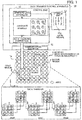
- the network 1 is a two-dimensional torus or mesh interconnect.
- the generated Latin hypercube is the two-dimensional Latin square 13a.
- the size of the first region 2 is three nodes wide in each of the x direction (the horizontal direction in FIG. 1 ) and the y direction (the vertical direction in FIG. 1 ).
- the size of the generated Latin square 13a is three rows by three columns (i.e., the number of symbols in each dimension is "3").
- the three symbols "0", "1", and "2" are used as the symbols set in the Latin square 13a.
- the Latin square 13a the three symbols aligned in the row direction and the column direction are different.
- the symbols in the Latin square 13a are associated with 3 ⁇ 3 nodes in the first region 2.
- identifiers from “1” to “9” are assigned to the nine first nodes.
- the symbol “0” is associated with a first node set composed of the identifiers "1", "5", and “9".
- the symbol “1” is associated with a first node set composed of the identifiers "2", “6", and “7”.
- the symbol “2” is associated with a first node set composed of the identifiers "3", "4", and "8".
- instructions for parallel data transfers to second nodes in the second region 3 are issued to the plurality of first nodes in the first region 2 in order of the first node set corresponding to the symbol "0", the first node set corresponding to the symbol "1", and the first node set corresponding to the symbol "2".
- the instructions are issued so that the first node set that performs a second or subsequent data transfer commences the data transfer after data transfer by the preceding first node set in the order has been completed.
- the plurality of second nodes are also assigned identifiers in the same order as the plurality of first nodes.
- identifiers with ascending numbers are assigned starting from the lower left node (a position with the lowest x and y coordinates) and advancing to the right (the positive direction on the x axis), with identifiers with ascending numbers being assigned from left to right to the nodes on an upper row after the nodes on the bottom row have been assigned identifiers. Data is then transferred from the respective first nodes to the second nodes assigned the same identifiers.
- the first node set with the identifiers "1", “5" and “9” transfers data in parallel (step0).
- the first node set with the identifiers "2", “6” and “7” transfers data in parallel (step1).
- the first node set with the identifiers "3", "4" and “8” transfers data in parallel (step2).
- the first nodes in the same first node set carry out data transfers on different paths. It is possible for every first node in the first node set where data transfers are performed in parallel to transfer data on different communication paths. As a result, congestion is avoided during communication for data transfers and data is transferred efficiently.
- a value corresponding to the larger out of the shift between the first region 2 and the second region 3 in the direction where the ranges overlap and the largest dimension of the first region 2 in directions aside from the direction where the ranges overlap is set as the number of symbols in each dimension of the Latin hypercube.
- the second region 3 may have a layout produced by rotating the first region 2 around a predetermined axis (for example, around an axis perpendicular to the x-y plane).
- a predetermined axis for example, around an axis perpendicular to the x-y plane.
- the second region 3 is a region occupied by the first region 2 when the first region 2 has been moved in parallel with the directions of the x axis and y axis and rotated by 90° clockwise or counter-clockwise.
- the number of first nodes aligned in the second longest dimension out of the n dimensions of the first region 2 is the number of symbols in each dimension of the Latin hypercube.
- the symbols in one Latin hypercube selected from a plurality of Latin hypercubes are associated with a plurality of first nodes in the first region 2 in accordance with the respective positions of the first nodes.
- control unit 12 instructs the respective nodes in the plurality of first nodes to transmit half the data to be transferred on a first path.
- the control unit 12 also instructs the respective nodes in the plurality of second nodes to acquire the remaining half of the data to be transferred from the respective nodes in the plurality of first nodes on a second path that differs from the first path.
- control unit 12 can be realized by a processor included in the data transfer control apparatus 10.
- the storage unit 13 can also be realized by a memory included in the data transfer control apparatus 10, for example.
- the lines that connect the respective elements in FIG. 1 depict some of the communication paths and it is possible to set other communication paths aside from the communication paths that have been illustrated.
- the second embodiment realizes efficient migration of a job in a parallel computing system realized by a torus or mesh interconnect.
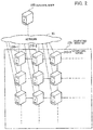
- FIG. 2 depicts an example configuration of a parallel computing system.
- a control node 100 is connected via a network 20 to computing nodes 210-1, 210-2, 210-3,... in a computing node set 200.
- the control node 100 is a computer that controls an HPC system constructed by the computing node set 200.
- the computing nodes 210-1, 210-2, 210-3, ... included in the computing node set 200 are computers that execute jobs in accordance with instructions from the control node 100.
- the control node 100 assigns a job to one or more computing nodes in the computing node set 200 and transmits an execution instruction for such job to the computing nodes assigned the job.
- the control node 100 is also capable of changing the computing nodes to which a job is assigned during execution of the job. In this case, the control node 100 moves the tasks that execute the job according to migration. When a job is migrated, the data of the job is transferred from migration source computing nodes to migration destination computing nodes.
- a network is constructed by connecting the computing nodes 210-1, 210-2, 210-3, ... included in the computing node set 200 by a torus or mesh interconnect.
- a mesh interconnect When a mesh interconnect is used, the computing nodes 210-1, 210-2, 210-3,... are aligned in n dimensions (where n is an integer of 2 or higher).
- Each of the computing nodes 210-1, 210-2, 210-3, ... is connected to other computing nodes that are adjacent in each dimension by a high-speed interconnect.
- a torus interconnect is used, the computing nodes at both ends in each dimension are connected an interconnect.
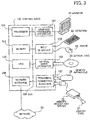
- FIG. 3 depicts an example hardware configuration of a control node.
- the control node 100 controls the apparatus as a whole using the processor 101.
- the processor 101 is connected via a bus 109 to a memory 102 and a plurality of peripherals.
- the processor 101 may be a multiprocessor.
- the processor 101 may be a CPU (Central Processing Unit), an MPU (Micro Processor Unit), or a DSP (Digital Signal Processor).
- Some or all of the functions realized by the processor 101 executing a program may be realized by an electronic circuit such as an ASIC (Application Specific Integrated Circuit) or a PLD (Programmable Logic Device).
- ASIC Application Specific Integrated Circuit
- PLD Programmable Logic Device
- the memory 102 is used as a main storage apparatus of the control node 100. At least part of an OS (Operating System) program and/or application program executed by the processor 101 is temporarily stored in the memory 102. Various data used in processing by the processor 101 is also stored in the memory 102. A volatile semiconductor storage apparatus such as RAM (Random Access Memory) is used as the memory 102.
- OS Operating System
- RAM Random Access Memory
- the peripherals connected to the bus 109 include an HDD (Hard Disk Drive) 103, a graphics processing apparatus 104, an input interface 105, an optical drive apparatus 106, a peripheral connecting interface 107, and a network interface 108.
- HDD Hard Disk Drive
- the HDD 103 magnetically reads and writes data onto internally held disks.
- the HDD 103 is used as an auxiliary storage apparatus of the control node 100.
- OS programs, application programs, and various data are stored in the HDD 103.
- the auxiliary storage apparatus it is also possible to use a nonvolatile semiconductor storage apparatus (or "Solid State Drive” (SSD)) such as flash memory.
- SSD Solid State Drive
- the graphics processing apparatus 104 is connected to a monitor 21.
- the graphics processing apparatus 104 displays images on the screen of the monitor 21 in accordance with instructions from the processor 101.
- a display apparatus that uses a CRT (Cathode Ray Tube), a liquid crystal display apparatus, or the like is used.
- the input interface 105 is connected to a keyboard 22 and a mouse 23.
- the input interface 105 transmits signals sent from the keyboard 22 and/or the mouse 23 to the processor 101.
- the mouse 23 is one example of a pointing device and that it is also possible to use other pointing devices, such as a touch panel, a tablet, a touchpad, and a trackball.
- the optical drive apparatus 106 uses laser light or the like to read data recorded on an optical disc 24.
- the optical disc 24 is a portable recording medium on which data is recorded so as to be readable using reflected light.
- the optical disc 24 may be a DVD (Digital Versatile Disc), a DVD-RAM, a CD-ROM (Compact Disc-Read Only Memory), a CD-R (Recordable) or a CD-RW (ReWritable).
- the peripheral connecting interface 107 is a communication interface for connecting peripherals to the control node 100.
- a memory apparatus 25 and a memory reader and writer 26 can be connected to the peripheral connecting interface 107.
- the memory apparatus 25 is a recording medium equipped with a function for communicating with the peripheral connecting interface 107.
- the memory reader and writer 26 is an apparatus that writes data onto a memory card 27 or reads data from the memory card 27.
- the memory card 27 is a card-shaped recording medium.
- the network interface 108 is connected to the network 20.
- the network interface 108 carries out transmission and reception of data to and from other computers and communication devices via the network 20.
- the apparatus described in the first embodiment can also be realized by the same hardware as the control node 100 depicted in FIG. 3 .
- the control node 100 By executing a program recorded on a computer-readable recording medium, for example, the control node 100 realizes the processing functions of the second embodiment.
- the program in which the processing content to be executed by the control node 100 is written may be recorded in advance on a variety of recording media.
- the program to be executed by the control node 100 can be stored in advance in the HDD 103.
- the processor 101 loads at least part of the program in the HDD 103 into the memory 102 and executes the program.
- the program to be executed by the control node 100 may also be recorded in advance in a portable recording medium such as the optical disc 24, the memory apparatus 25, or the memory card 27.
- the program stored on such portable recording medium can also be executed after being installed into the HDD 103 according to control by the processor 101, for example.
- the processor 101 is also capable of directly reading and executing the program from the portable recording medium.
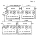
- FIG. 4 depicts an example of the hardware configuration of a computing node.
- the computing node 210-1 includes a CPU and memory unit 201 and a router 202.
- the CPU and memory unit 201 and the router 202 are connected by a plurality of communication interfaces ("network interface controllers" or "NIC") 203.
- NIC network interface controllers
- the other computing nodes 210-2, 210-4, and 210-5 have the same hardware configuration.
- the respective computing nodes often include a plurality of NIC 203.
- the CPU and memory unit 201 and the router 202 are connected by four NIC 203.
- the transfer bandwidth for transmission from the CPU and memory unit 201 is four times the transfer bandwidth of one NIC 203.
- the communication speed between one pair of routers is normally below the transfer bandwidth for transmission from the CPU and memory unit 201. That is, provided that the communication direction and communication procedure are the same, the speed of communication between any two computing nodes is limited to the communication speed between the routers. This means that it is important to efficiently perform data transfers that accompany communication between routers.
- FIG 5 depicts functions of the apparatuses in a parallel computing system.
- the control node 100 includes a job manager 110.
- the job manager 110 controls the execution of a job that uses the computing nodes 210-1, 210-2, 210-3, ....
- the job manager 110 assigns computing nodes to a job that has been loaded and gives instructions for migration to computing nodes that are executing a job.
- the job manager 110 includes a migration information storage unit 111, a migration destination deciding unit 112, a Latin square generating unit 113, and a data transfer managing unit 114.
- the migration information storage unit 111 stores information to be used during migration.
- the migration information storage unit 111 stores a computing node group that is the migration source of the job to be migrated, a computing node group that is the migration destination, a Latin square expressing the execution order of migration, and the like.
- part of the storage region of the memory 102 is used as the migration information storage unit 111.
- the migration destination deciding unit 112 decides the computing nodes that are the migration destination of the job to be migrated.
- the migration destination deciding unit 112 detects, on the network with a torus or mesh interconnect, a submesh that includes a number of vacant computing nodes that is at least equal to the number of computing nodes used to execute the job.
- the submesh is a rectangular region, while for a network with a three-dimensional torus or mesh interconnect, the submesh is a cuboid region.
- the expression "vacant computing node” refers to a computing node that is not presently executing a job.
- the migration destination deciding unit 112 sets the computing nodes in the detected submesh as the migration destination computing node group.
- the migration destination deciding unit 112 stores information indicating the migration source computing node group presently executing the job and information indicating the set migration destination computing node group in the migration information storage unit 111.
- the Latin square generating unit 113 generates a Latin square expressing an efficient execution procedure for migration.
- the Latin square generating unit 113 stores the generated Latin square in the migration information storage unit 111.
- the data transfer managing unit 114 manages transfers of migration data. As one example, the data transfer managing unit 114 associates numeric values in the generated Latin square with computing nodes in the submesh of the migration source computing node group. The data transfer managing unit 114 sets the numeric values of the Latin square as the order in which the computing nodes associated with such numeric values are to transfer the migration data. The data transfer managing unit 114 then issues transfer instructions for migration data to the respective migration source computing nodes so that the migration data at the migration source computing nodes is transferred in accordance with the transfer order set for the computing nodes.
- the computing node 210-1 includes a migration unit 211 and a job data storage unit 212.
- the migration unit 211 migrates a job in accordance with an instruction from the control node 100. For example, on receiving an instruction for migration of a job being executed, the migration unit 211 acquires the data of such job from the job data storage unit 212 and transmits the data to the appropriate migration destination computing node.
- the job data storage unit 212 stores data used in the execution of a job.
- the job data storage unit 212 is a memory of the computing node 210-1, for example.
- the computing nodes 210-2, 210-3, ... aside from the computing node 210-1 have the same elements as the computing node 210-1.
- a computing node group in a submesh is assigned to the job.
- data is transmitted from the respective computing nodes in the migration source computing node group to the respective computing nodes in the migration destination computing node group.
- the job manager 110 controls the order in which the respective migration source computing nodes transmit data.
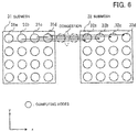
- FIG. 6 depicts a first example of a situation where congestion occurs.
- a job that is being executed by a computing node group in a 4 ⁇ 4 submesh 31 is migrated to a computing node group in a 4 ⁇ 4 submesh 32 at a position produced by moving the submesh 31 parallel to the x axis direction.
- the migration data of the computing node 31a is transmitted to the computing node 32a
- the migration data of the computing node 31 b is transmitted to the computing node 32b
- the migration data of the computing node 31c is transmitted to the computing node 32c
- the migration data of the computing node 31d is transmitted to the computing node 32d.
- simultaneous transmission of migration data from the migration source computing nodes 31a to 31d to the migration destination computing nodes 32a to 32d is started.
- migration data is transferred in this way in only the x axis direction, when the migration source computing nodes 31a to 31d simultaneously start the transmission of migration data, congestion occurs due to a maximum of four transfers being multiplexed midway on the communication path.
- FIG 7 depicts a second example of a situation where congestion occurs.
- a job that is executed by a computing node group in a 4 ⁇ 4 submesh 33 is migrated to a computing node group in a 4 ⁇ 4 submesh 34 at a position produced by moving the submesh 33 parallel to the x axis and the y axis direction.
- the routing of migration data at this time is performed in the order x axis direction, y axis direction.
- the migration data of the computing node 33a is transmitted to the computing node 34a
- the migration data of the computing node 33b is transmitted to the computing node 34b
- the migration data of the computing node 33c is transmitted to the computing node 34c
- the migration data of the computing node 33d is transmitted to the computing node 34d
- the migration data of the computing node 33e is transmitted to the computing node 34e
- the migration data of the computing node 33f is transmitted to the computing node 34f
- the migration data of the computing node 33g is transmitted to the computing node 34g.
- the simultaneous transmission of migration data from the migration source computing nodes 33a to 33g to the migration destination computing nodes 34a to 34g is started.
- migration data is transferred in this way in the x axis direction and the y axis direction
- the migration source computing nodes 33a to 33g simultaneously start the transmission of migration data, congestion occurs due to a maximum of four transfers being multiplexed for communication in the x axis direction and a maximum of four transfers being multiplexed for communication in the y axis direction.
- Congestion on a communication path is a main cause of network delays and packet loss, which can result in a large drop in communication performance.
- congestion can be avoided by transmitting migration data in order for each column in the y axis direction in the submesh 31. That is, first, the migration data is simultaneously transferred by four computing nodes that belong to the same column as the computing node 31a and then migration data is simultaneously transferred by four computing nodes that belong to the same column as the computing node 31b. After this, in the same way, migration data is transferred in order of the four computing nodes that belong to the same column as the computing node 31c and the four computing nodes that belong to the same column as the computing node 31d. By doing so, data communication can be performed without congestion.
- the computing node group to which the job to be migrated has been assigned is divided into a plurality of computing node sets and data is transferred in order in a plurality of communication steps for each computing node set.
- each computing node has a unique x axis coordinate and a unique y axis coordinate.
- the respective nodes in the computing node group to which a job has been assigned are all set so as to belong to one of the communication steps. To satisfy such conditions, it is possible to use a Latin square as the method of deciding the order of communication.
- FIG. 8 depicts examples of Latin squares.
- k where k is an integer of 1 or higher
- the Latin squares 41 to 43 can also be referred to as "Latin rectangles".
- the numeric values 1 to n are used as the symbols in the Latin square 41 to 43.
- 576 combinations can be generated.
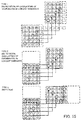
- FIG. 9 depicts an example of transfer of migration data using a Latin square.
- a job that is being executed by the computing nodes in a 4 ⁇ 4 submesh 51 is moved by migration to another 4 ⁇ 4 submesh 52.
- the computing nodes included in the submeshes 51 and 52 are assigned the identification numbers in the submeshes 51 and 52.
- the circles indicate computing nodes and the numeric values inside the circles are identification numbers in the submeshes 51 and 52.
- the transferring of migration data during migration is performed using the Latin square 41.
- the positions of the various numeric values in the Latin square 41 correspond to the positions in the submesh 51 of the respective migration source computing nodes.
- the numeric values of the Latin square 41 express the order in which the corresponding computing nodes are to transmit migration data.
- the computing nodes (with the identifiers "1", “6”, “11”, and “16") corresponding to "0" in the Latin square 41 transmit migration data to the computing nodes with the same identifiers in the submesh 52.
- the computing nodes (with the identifiers "2”, “7”, “12”, and “13") corresponding to "1" in the Latin square 41 transmit migration data to the computing nodes with the same identifiers in the submesh 52.
- FIG 10 also depicts the same example of transfer of migration data using a Latin square.
- the computing nodes (with the identifiers "3", “8”, “9”, and “14") corresponding to "2" in the Latin square 41 transmit migration data to the computing nodes with the same identifiers in the submesh 52.
- the computing nodes (with the identifiers "4", "5", "10", and “15") corresponding to "3" in the Latin square 41 transmit migration data to the computing nodes with the same identifiers in the submesh 52.
- the Latin square 41 depicted in FIG 9 is a normalized Latin square. This means that after computing nodes aligned in the diagonal direction have transferred data in step0, it is possible to perform data transfers in the order depicted in FIGS. 9 and 10 by shifting the computing nodes to perform communication to the right (in the plus direction on the x axis) in each communication step. Note that when the rightward shift moves beyond the range of the submesh 51, the computing nodes at the lowest numbered positions on the opposite side are selected to perform communication.
- the transmission speed in each communication step is maintained since congestion during communication is avoided.
- the transfer time for the migration data of all nodes is four times the time taken by communication between a pair of nodes.
- the computing node set that performs simultaneous communication in step0 is aligned in the diagonal direction and in the following steps also, a computing node set at a position where such coordinates have been shifted is used.
- the width of the submesh in the x axis direction and the width in the y axis direction are different. Note that in this second embodiment, it is assumed that the gaps between the computing nodes in the x axis direction and the y axis direction are "1".
- the width in the x axis direction and the width in the y axis direction in the submesh are expressed by the number of computing nodes in the x axis direction and the number of computing nodes in the y axis direction in the submesh.
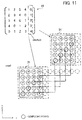
- FIG. 11 depicts an example of transfer of migration data when the dimensions of the submesh are different.
- FIG. 11 depicts an example where a job that is assigned to computing nodes in a submesh 53 with a width "4" (equivalent to four computing nodes) in the x axis direction and a width "5" (equivalent to five computing nodes) in the y axis direction is migrated to computing nodes in another 4 ⁇ 5 submesh 54.
- the Latin square generating unit 113 generates a Latin square that matches the length of the longer (or longest) dimension. In the example in FIG. 11 , a 5 ⁇ 5 Latin square 44 is generated.
- the numeric values of the Latin square 44 are associated with the computing nodes in a 5 ⁇ 5 region that includes the submeshes 53 and 54. In this case, the rightmost column of the Latin square 44 is not used. That is, the numeric values in this column are not associated with computing nodes in the submeshes 53 and 54.
- the computing nodes in the submesh 53 transfer the migration data in an order in keeping with the corresponding numeric values in the Latin square 44. As one example, computing nodes with the identifiers "1", “6", “11", and "16" in the submesh 53 simultaneously transmit migration data in the first step (step0).
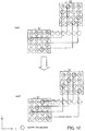
- FIG. 12 depicts a first example of where a plurality of Latin squares have been stacked.
- the migration source computing node group and the migration destination computing node group have overlapping coordinates in one dimension, it is possible to stack two Latin squares and reduce the number of communication steps required to transfer the migration data.
- FIG. 12 depicts an example case where migration is performed from computing nodes in a 4x 10 submesh 55 to computing nodes in a 4 ⁇ 10 submesh 56 of the same size.
- the migration source submesh 55 and the migration destination submesh 56 have ranges that overlap in the y axis direction.
- the distance by which the submeshes are displaced in the y axis direction is "3" (equivalent to 3 nodes).
- Three Latin squares 41 are then stacked and associated with the respective computing nodes in the submeshes 55 and 56. By doing so, all of the computing nodes in the submeshes 55 and 56 can be associated with one of the numeric values in the Latin square 41.
- the computing nodes corresponding to the respective numeric values transmit migration data in the order of the numeric values in the Latin square.
- the computing nodes with the identifiers "2", “7”, “12”, “13”, “18”, “23”, “28”, "29”, “34”, and “39” simultaneously transmit migration data.
- the computing nodes corresponding to the numeric values in the Latin square 41 transmit data in accordance with the numeric values, it is possible to complete the transfer of migration data in four steps.
- FIG. 13 depicts a second example of where a plurality of Latin squares have been stacked.
- FIG. 13 depicts an example where migration is performed from computing nodes in a 4 ⁇ 11 submesh 57 to computing nodes in a 4 ⁇ 11 submesh 58 of the same size.
- the migration source submesh 57 and the migration destination submesh 58 have ranges that overlap in the y axis direction.
- the distance by which the submeshes are displaced in the y axis direction is "5" (equivalent to 5 nodes).
- Three Latin squares 44 are then stacked and associated with the respective computing nodes in the submeshes 57 and 58. By doing so, all of the computing nodes in the submeshes 57 and 58 can be associated with one of the numeric values in the Latin square 44.
- the computing nodes corresponding to the respective numeric values in the Latin square then transmit migration data in the order of the numeric values of the Latin square.
- the computing nodes with the identifiers "1", “6", “11”, “16”, “21”, “26”, “31”, “36”, and “41” simultaneously transmit migration data.
- the computing nodes corresponding to the numeric values in the Latin square 44 perform data communication in accordance with such numeric values, it is possible to complete the transfer of migration data in five steps.
- FIG. 14 depicts an example of migration that involves rotation of the layout of computing nodes.
- the layout of a computing node group assigned a job is rotated clockwise by 90° when migration is performed.
- a Latin square 45 in which the layout of the numeric values in the Latin square 41 showing the transmission order of migration data for a migration source submesh 59 is rotated clockwise by 90° is generated.
- the Latin square 45 expresses the order of data reception by computing nodes in a migration destination submesh 60. In this way, by using the Latin squares 41 and 45, it is possible to perform migration while avoiding congestion, even when the layout of the computing nodes is rotated.
- a plurality of methods can conceivably be used to transfer migration data using a Latin square.
- the Latin square that enables data to be transferred most efficiently is generated.
- An appropriate Latin square is determined based on whether rotation is performed and whether there is overlapping of the coordinates in the longest dimension between the migration source and the migration destination submeshes.
- FIG. 15 depicts types of Latin square to be generated.
- Type 1 is for a case where there is no rotation of the layout of the computing nodes and no overlapping of the ranges in the longer dimension of the migration source submesh and the migration destination submesh.
- a Latin square where the number of symbols in each row and column is the same as the number of computing nodes in the longer dimension of the migration source submesh is generated.
- Type 2 is for a case where there is no rotation of the layout of computing nodes but the ranges in the longer dimension of the migration source submesh and the migration destination submesh overlap.
- a value that is the larger out of the displacement in the longer dimension between the migration source submesh and the migration destination submesh and the width in the shorter dimension of the migration source submesh is found, and a Latin square where the number of symbols in each row and column is equal to such value is generated. The generated Latin square is then stacked.
- Type 3 is for a case where there is rotation of the layout of computing nodes.
- a Latin square where the number of symbols in each row and column is the same as the number of computing nodes in the shorter dimension of the migration source submesh is generated. The generated Latin square is then stacked.
- FIG. 16 is a flowchart depicting one example of the procedure of the migration process.
- the migration process is executed when a migration instruction for a job has been inputted, for example.
- Step S101 The migration destination deciding unit 112 searches for a computing node group to be set as the migration destination of the job to be migrated. As one example, the migration destination deciding unit 112 determines the number of computing nodes to be assigned to the job in accordance with the parallelism of the job. Next, the migration destination deciding unit 112 searches for a submesh (a rectangular region) that includes an equal number of vacant computing nodes to the number of computing nodes to be assigned. When a plurality of suitable submeshes have been detected, as one example the migration destination deciding unit 112 selects a submesh whose position is close to the computing node group presently assigned the job.
- a submesh a rectangular region
- the migration destination deciding unit 112 then sets the computing node group included in the selected submesh as the migration destination of the job to be migrated.
- the migration destination deciding unit 112 stores information indicating the selected migration destination computing node group in the migration information storage unit 111.
- the migration destination deciding unit 112 stores information indicating the range (upper limit and lower limit) in each dimension of the submesh that includes the computing node group in the migration information storage unit 111.
- Step S102 The Latin square generating unit 113 generates a Latin square expressing the transfer order of the migration data.
- the Latin square generating process is described in detail later (see FIG. 17 ).
- Step S103 The data transfer managing unit 114 performs a transfer process for migration data from the migration source computing node group to the migration destination computing node group using the generated Latin square.
- the migration data transfer process is described in detail later (see FIG. 19 ).
- FIG. 17 is a flowchart depicting one example of a procedure of the Latin square generating process.
- the Latin square generating unit 113 compares the migration source computing node group and the migration destination computing node group and determines whether the layout of the computing nodes is rotated during migration. As one example, the Latin square generating unit 113 determines that the layout has been rotated when the lengths in the different dimensions of the migration source and the migration destination submeshes differ and the longest dimension of the migration source submesh and the longest dimension of the migration destination submesh are in different dimensions.
- the processing proceeds to step S112.
- the layout of the computing nodes is not rotated, the processing proceeds to step S113.
- the Latin square generating unit 113 generates a Latin square where the number of symbols on each row and column is the width of the shortest dimension (Min (x,y)). The Latin square generating unit 113 then stacks a plurality of Latin squares that are the same as the generated Latin square. After this, the Latin square generating unit 113 stores the generated Latin square in the migration information storage unit 111 and ends the Latin square generating process.
- Step S113 The Latin square generating unit 113 determines, when the layout is not rotated, whether the ranges of the longest dimension of the migration source submesh and the migration destination submesh overlap. When there is overlapping, the processing proceeds to step S115. When there is no overlapping, the processing proceeds to step S114.
- Step S114 The Latin square generating unit 113 generates a Latin square where the number of symbols on each row and column is the width of the longest dimension (Max (x,y)). The Latin square generating unit 113 then stores the generated Latin square in the migration information storage unit 111 and ends the Latin square generating process.
- Step S115 The Latin square generating unit 113 generates a Latin square where the number of symbols on each row and column is the longer out of the displacement between the migration source and the migration destination submeshes and the shorter dimension of the submeshes.
- the Latin square generating unit 113 then stacks a plurality of Latin squares that are the same as the generated Latin square. After this, the Latin square generating unit 113 stores the generated Latin square in the migration information storage unit 111 and ends the Latin square generating process.
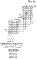
- FIG. 18 depicts variables used in the migration data transfer process.
- the data transfer managing unit 114 acquires information indicating a migration source submesh 61 and a migration destination submesh 62 from the migration information storage unit 111.
- the information indicating the migration source submesh 61 includes coordinates (x s0 , y s0 ) of a computing node 61a that has the lowest x coordinate and y coordinate in the submesh 61 and coordinates (x sm , y sm ) of a computing node 61b that has the highest x coordinate and y coordinate.
- the information indicating the migration destination submesh 62 includes coordinates (x r0 , y r0 ) of a computing node 62a that has the lowest x coordinate and y coordinate in the submesh 62 and coordinates (x rm , y rm ) of a computing node 62b that has the highest x coordinate and y coordinate. From the coordinates (x r0 , y r0 ) of the computing node 62a and the coordinates of the computing node 62b (x nn , y nn ), it is possible to specify the region of the submesh 62 and to calculate the dimensions in the x axis and y axis directions of the submesh 62.
- FIG. 18 depicts an example where the layout of computing nodes is not rotated and there is no overlapping of the submeshes 61 and 62 in the longest dimension.
- the shorter (Min (x sz, y sz )) of the dimensions of the submesh 61 in the x axis direction and the y axis direction is set as the number of computing nodes to perform simultaneous transmission in one communication step (i.e., the number of simultaneous communications).
- the longer (Max (x sz ,y sz )) of the dimensions of the submesh 61 in the x axis direction and the y axis direction is set as the number of communication steps.
- the computing nodes with the identifiers "1”, “6”, “11”, and “16” simultaneously transmit data.
- the computing nodes with the identifiers "2”, “7", “12”, and “17” simultaneously transmit data.
- the computing nodes with the identifiers "3”, “8”, “13", and “18” simultaneously transmit data.
- the computing nodes with the identifiers "4", “9", "14", and “19” simultaneously transmit data.
- the computing nodes with the identifiers "5", “10", “15”, and “20” simultaneously transmit data.
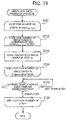
- FIG 19 This processing is depicted in a flowchart in FIG 19 , which depicts one example of the procedure of the migration data transfer process.
- Step S123 The data transfer managing unit 114 performs data transfer between nodes in the m th communication step.
- the data transfer managing unit 114 instructs the computing nodes that are to transmit migration data in the m th step to transmit migration data.
- a migration data transmission instruction includes the identifier of the migration destination of the migration data (for example, coordinates indicating the position on the network). Such transmission instruction is performed by computing nodes that transmit migration data in the n th step.
- Step S124 When all of the computing nodes that perform data transfer between nodes in the m th step have started transmitting data, the data transfer managing unit 114 proceeds to step S125.
- Step S125 The data transfer managing unit 114 determines whether data transfer (simultaneous communication) between nodes in the m th step has been completed. As one example, on receiving notification of completion of data transfer from all of the computing nodes that have transmitted migration data, the data transfer managing unit 114 determines that the simultaneous communication has been completed. When the simultaneous communication has been completed, the processing proceeds to step S126. When the simultaneous communication has not been completed, the processing in step S125 is repeated until the simultaneous communication is complete.
- Step S126 When the processing has been completed for the number of communication steps, the data transfer managing unit 114 ends the migration data transfer process.
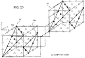
- FIG 20 depicts an example of a network with a three-dimensional torus or mesh interconnect.
- a computing node group in a cuboid submesh 63 is assigned to a job.
- a computing node group in a submesh 64 that is also cuboid is decided as the migration destination.
- congestion can be avoided by preventing computing nodes with the same x axis, y axis, and z axis coordinates from performing data communication in the same communication step.
- a job is migrated from a computing node group in a 4x4x4 three-dimensional submesh 63 to a computing node group in the submesh 64.
- the computing nodes are located on planes 63a and 63b, there is no duplication of coordinates in the x, y, and z axes and simultaneous communication can be performed without congestion.
- the number of computing nodes capable of simultaneous communication is sixteen and the number of communication steps is four.
- the numbers are selected so as to have a Latin square relationship on every plane (xy plane, xz plane, and yz plane) that is a combination of two axes out of the n-dimensional coordinates. Such relationship is called a "Latin hypercube".
- FIG. 21 depicts an example of a Latin hypercube.
- a Latin hypercube is an expression where numeric values on any plane that is parallel with one of the xy plane, the xz plane, and the zy plane form a Latin square. Note that FIG. 21 illustrates one example of a 4 ⁇ 4 ⁇ 4 Latin hypercube, and that a plurality of combinations of symbols that form a Latin hypercube exist.
- n-dimensional torus or mesh interconnect As one example, it is possible to use a network with a six-dimensional mesh/torus interconnect referred to as a Tofu (Torus Fusion) interconnect. That is, in an HPC with an n-dimension direct network (a mesh interconnect, torus interconnect, or the like) it is possible during diskless migration of a job executed in parallel by a cuboid node set to efficiently transfer and move migration data between the migration source and destination.
- Tofu Torus Fusion
- a job manager confirms the communication order, and control over execution of data transfer is performed by the computing node group that transfers the migration data itself.
- the third embodiment is described below focusing on the differences with the second embodiment.
- FIG 22 is a sequence chart depicting a migration data transfer procedure in the third embodiment.
- Step S210 The job manager 110 of the control node 100 uses a Latin square to decide the data transmission order of the migration source computing nodes for the migration.
- the job manager 110 generates an appropriate Latin square based on the form of the migration source and migration destination submeshes, the position information, and whether rotation is performed, and decides the node group to perform simultaneous communication in each communication step.
- the generation process for the Latin square is the same as the process in the second embodiment depicted in FIG. 17 .
- a computing node set 310 that carries out simultaneous communication in (step0), a computing node set 320 that carries out simultaneous communication in (step1), ..., a computing node set 330 that carries out simultaneous communication in (stepN) are decided.
- the job manager 110 provides communication order information to all of the computing nodes that are to perform transmission.
- the communication order information includes the computing nodes that are the transmission destinations, the communication step number to which each transmission belongs, and the total number of communication steps.
- each computing node After receiving the communication order information, each computing node enters a barrier synchronization standby state.
- Step S215 After completion of barrier synchronization for all of the computing nodes, the computing nodes in the computing node set 310 for the communication step number (step0) perform a transmission process for migration data.
- Step S216 Each computing node in the computing node set 310 switches to a barrier synchronization standby state after transmitting the migration data.
- Steps S217 and S2128 The computing nodes that do not belong to the communication step number (step0) again enter a barrier synchronization standby state.
- Step S219) When the communication in the communication step number (step0) is completed and the barrier synchronization of all of the computing nodes is completed again, each node in the computing node set 320 of the communication step number (step1) carries out the transmission process for migration data. After this, barrier synchronization and data communication in each communication step are repeated in the same way.
- Step S220 When communication in the communication step number (step N-1) has been completed and barrier synchronization of every computing node has been completed again, the respective computing nodes in the computing node set 330 of the communication step number (step N) carry out the transmission process for migration data.
- Step S221) When communication in the communication step number (step N) has been completed, one of the computing nodes in the computing node set 330 notifies the control node 100 of the completion of the migration data transfer process.
- a Latin square capable of communicating efficiently is selected out of a plurality of Latin squares in accordance with the communication state on a path during transfer of migration data and the selected Latin square is used in data transfer.
- the fourth embodiment is described below focusing on the differences with the second embodiment.
- a job is assigned to a cuboid of a minimum size in a direct network with a torus or mesh interconnect
- job migration it may be necessary to pass a region that is executing another job.
- the influence of communication by the nodes that are passed is not considered.
- the control node 100 before performing the transferring of migration data, acquires the state of communication aside from the migrated job present on the path used to communicate the migration data. The control node 100 then selects a Latin square that minimizes the collisions between communication. That is, the Latin square generating unit 113 of the control node 100 performs an optimization process that selects an appropriate Latin square out of a plurality of Latin squares. For example, by performing the following two processes, the Latin square generating unit 113 optimizes the transfer order of migration data.
- the amount of migration data to be transferred per node can be anything from several GB to tens or hundreds of GB. It is therefore imagined that the bandwidth of the communication paths will become almost completely occupied. That is, when other communication is present on a communication path, the transfer speed of the migration data is affected. In cases where the communication state of the path changes while communication is being performed in order according to the symbols (numbers) in a Latin square, further optimization can be achieved by selecting an appropriate order.
- information on factors that change the communication state on the path is managed by the job manager 110.
- the factors that change the communication state on the path are Factor a and Factor b described below.
- the node layout assigned to a job on a communication scheduled path changes.
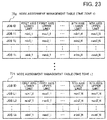
- the job manager 110 stores a schedule (node assignment management table) in which the assignment of jobs to respective nodes in each unit time is decided.
- FIG. 23 depicts an example of a node assignment management table.
- the job manager 110 decides a submesh (a cuboid region for a three-dimensional network) indicating the computing node group to be assigned to each job.
- the job manager 110 then generates node assignment management tables 71a, ..., 71n, which store the minimum value and maximum value of the coordinates in each axis of the assigned computing node groups, for each time zone that is a unit for assignment and stores the node assignment management tables 71a, ..., 71n in the memory 102.
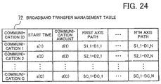
- FIG. 24 depicts one example of a broadband transfer management table.
- the communication path between a pair of computing nodes includes a maximum of N-1 changes in direction. For this reason, the communication paths are managed by being divided into N linear paths in each axis.
- a communication start time, communication amount, and a communication path on each axis from the first axis to the N th axis is set for each identifier (communication ID) of communication that has been scheduled.
- the fourth embodiment there is a premise that (factor a) and (factor b) described above exist and it is assumed that communication aside from the job (by devices aside from the computing node group assigned the job) is managed using a broadband transfer management table. That is, a component for managing communication for "broadband transfers" is provided in the job manager 110. For example, the respective jobs that perform broadband transfers notify the job manager 110 of the paths used for communication before the start of communication. The job manager 110 records the communication content of the broadband transfers in accordance with the notified content in a broadband transfer management table 72.
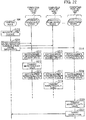
- FIG. 25 depicts one example of the procedure of the Latin square selection process.
- Step S301 The job manager 110 finds a migration end scheduled time for a case where there is no interference during communication.
- the job manager 110 calculates the migration end scheduled time To for a case where there is no interference with other jobs or "broadband transfers" during communication, relative to a migration start scheduled time S 0 according to the formula given below.
- T 0 S 0 + ⁇ amount of communicated data per path for transferring migration data / transfer bandwidth
- the paths for transferring migration data include a path in the x axis direction, a path in the y axis direction, and a path in the z axis direction, for example.
- the transfer bandwidth is a value set in advance (for example, 5GB).
- the migration end scheduled time T is found by adding the total ( ⁇ ) of the communication time (amount of communicated data/transfer bandwidth) for each path to the migration start scheduled time So.
- Step S302 The job manager 110 determines whether there is the possibility of interference with another job or "broadband transfer". As one example, the job manager 110 determines whether the following two conditions are satisfied.
- Condition 1 A job is present at a computing node on the migration data transfer path during the period from So to T 0 .
- s(i) is the start time of communication for the communication ID "i" (where i is an integer of 1 or higher).
- d(i) is the communication amount for the communication ID "i”. The values of s(i) and d(i) for each communication can be acquired from the broadband transfer management table 72.
- the job manager 110 determines that there is the possibility of interference. When there is the possibility of interference, the processing proceeds to step S304. When there is no possibility of interference, the processing proceeds to step S303.
- Step S303 The job manager 110 decides to use a Latin square that has been decided in advance. After this, the Latin square deciding process ends.
- Step S304 The job manager 110 evaluates a degree of interference to communication for each of a plurality of Latin squares provided in advance for each computing node set (a plurality of computing nodes corresponding to the same symbol in a Latin square) that is to simultaneously transfer data. Based on the degree of interference to communication, the end scheduled time is then calculated for each Latin square. The evaluation process for the degree of interference to communication is described in detail later (see FIG. 26 ).
- Step S305 The job manager 110 selects a Latin square with the earliest end scheduled time for migration out of the plurality of Latin squares as the Latin square to be used to transfer migration data.
- FIG. 26 is a flowchart depicting one example of the procedure of the evaluation process for the degree of interference to communication.
- Step S311 The job manager 110 selects an unprocessed Latin square out of a plurality of Latin squares provided in advance.
- Step S312 The job manager 110 finds a number of jobs n 1 to be executed on a path used for migration in a time period from the migration start scheduled time So to the migration end scheduled time T 0 for each symbol in the selected Latin square.
- the job manager 110 selects node assignment management tables of time zones with parts that overlap the time zone (So, To).
- the job manager 110 extracts, from the selected node assignment management tables and for each symbol in the selected Latin square, jobs where a range of the submesh to which the computing node group assigned to the job belongs at least partially overlaps a path used for migration. That is, since the path used for migration differs for each symbol, the jobs executed on the path also differ for each symbol.
- the range of a submesh is expressed by an upper limit and lower limit of each coordinate axis in the node assignment management table.
- Step S313 The job manager 110 finds the number n2 of "broadband transfers" that intersect the path used for migration in the time zone from S 0 to T 0 for each symbol in the selected Latin square.
- the job manager 110 extracts, from a management table for "broadband transfers" with a time zone with a part that overlaps the time zone "S 0 , T 0 ", communication paths with parts where a cuboid coordinate range of the communication path overlaps a path used for migration and finds the number of extracted paths.
- Step S314 The job manager 110 multiplies n 1 and n 2 by respective weighting coefficients and sets the total of such results as the "degree of interference to communication for each symbol".
- A1 is the "average bandwidth used by internal communication of a job/bandwidth of link”.
- A2 is set at "1".
- Step S316 The job manager 110 determines whether there is an unprocessed Latin square. When there is an unprocessed Latin square, the processing proceeds to step S31 1. When there is no unprocessed Latin square, the degree of interference evaluation process ends.
- an appropriate Latin square is selected based on information on broadband transfers that have been scheduled, it is also possible to acquire statistical information on the present communication amount and to select an appropriate Latin square based on such statistical information.
- the fifth embodiment improves the efficiency of data transfers by using two data transfer paths between a pair of computing nodes.
- a procedure where data is sent from a present node to a peer node and a procedure (“get”, “read”) data from is acquired by a present node from a peer node can be used as means of communication between computing nodes.
- the communication route may differ between a case where a put is performed from the migration source to the migration destination and a case where a get is performed from the migration destination to the migration source.
- FIG 27 depicts an example of data communication paths in the fifth embodiment.
- data is transferred in order of the x axis, y axis (the counter clockwise direction in FIG. 27 ).
- the migration destination computing nodes acquire data via routes in the order of x axis, y axis.
- migration data is transferred in the order y axis, x axis (in the clockwise direction) from the transmission source. That is, different communication paths are used for communication according to a put and a get.
- the job manager 110 of the control node 100 notifies both the migration source computing nodes and the migration destination computing nodes of the order in which the respective computing nodes are to perform data communication.
- the job manager 110 transmits the generated Latin square to all of the migration source computing nodes and all of the migration destination computing nodes.
- the invention also provides a computer program or a computer program product for carrying out any of the methods described herein, and a computer readable medium having stored thereon a program for carrying out any of the methods described herein.
- a computer program embodying the invention may be stored on a computer-readable medium, or it could, for example, be in the form of a signal such as a downloadable data signal provided from an Internet website, or it could be in any other form.
Landscapes
- Engineering & Computer Science (AREA)
- Theoretical Computer Science (AREA)
- Physics & Mathematics (AREA)
- Computer Hardware Design (AREA)
- Mathematical Physics (AREA)
- Software Systems (AREA)
- General Engineering & Computer Science (AREA)
- General Physics & Mathematics (AREA)
- Signal Processing (AREA)
- Computer Networks & Wireless Communication (AREA)
- Multi Processors (AREA)
- Information Transfer Systems (AREA)
- Information Retrieval, Db Structures And Fs Structures Therefor (AREA)
Applications Claiming Priority (1)
| Application Number | Priority Date | Filing Date | Title |
|---|---|---|---|
| JP2015037641A JP6459630B2 (ja) | 2015-02-27 | 2015-02-27 | データ転送制御装置、データ転送制御プログラム、および並列計算システム |
Publications (2)
| Publication Number | Publication Date |
|---|---|
| EP3062233A2 true EP3062233A2 (de) | 2016-08-31 |
| EP3062233A3 EP3062233A3 (de) | 2017-06-21 |
Family
ID=55310651
Family Applications (1)
| Application Number | Title | Priority Date | Filing Date |
|---|---|---|---|
| EP16152693.4A Withdrawn EP3062233A3 (de) | 2015-02-27 | 2016-01-26 | Datenübertragungssteuerungsvorrichtung, computerprogramm und parallelrechnersystem |
Country Status (3)
| Country | Link |
|---|---|
| US (1) | US10091280B2 (de) |
| EP (1) | EP3062233A3 (de) |
| JP (1) | JP6459630B2 (de) |
Cited By (2)
| Publication number | Priority date | Publication date | Assignee | Title |
|---|---|---|---|---|
| US20220173973A1 (en) * | 2020-11-30 | 2022-06-02 | Google Llc | Connecting processors using twisted torus configurations |
| US12335099B2 (en) | 2020-10-19 | 2025-06-17 | Google Llc | Enhanced reconfigurable interconnect network |
Families Citing this family (3)
| Publication number | Priority date | Publication date | Assignee | Title |
|---|---|---|---|---|
| JPWO2017090517A1 (ja) * | 2015-11-24 | 2018-09-06 | 日本電気株式会社 | ソフトウェアストレージユニット、バックアップ方法、およびバックアップ制御プログラムが記録された記録媒体 |
| CN107733810B (zh) * | 2016-08-10 | 2020-11-27 | 华为技术有限公司 | 一种确定路由的方法、装置及通信设备 |
| CN108520317B (zh) * | 2018-03-27 | 2021-07-27 | 华中科技大学 | 一种水电系统联合优化调度的拉丁方动态规划降维方法 |
Citations (1)
| Publication number | Priority date | Publication date | Assignee | Title |
|---|---|---|---|---|
| JP2002507300A (ja) | 1997-06-30 | 2002-03-05 | ボプス インコーポレイテッド | マニホールドアレイプロセッサ |
Family Cites Families (7)
| Publication number | Priority date | Publication date | Assignee | Title |
|---|---|---|---|---|
| US6456588B1 (en) * | 1997-04-21 | 2002-09-24 | At&T Corp. | Hypercube routing and restoration in telecommunications networks |
| US6763519B1 (en) * | 1999-05-05 | 2004-07-13 | Sychron Inc. | Multiprogrammed multiprocessor system with lobally controlled communication and signature controlled scheduling |
| US7466656B2 (en) * | 2004-10-26 | 2008-12-16 | International Business Machines Corporation | Method, apparatus and program storage device for efficient construction of network overlays through interconnection topology embedding |
| US7853639B2 (en) * | 2006-09-12 | 2010-12-14 | International Business Machines Corporation | Performing process migration with allreduce operations |
| JP5849486B2 (ja) * | 2011-07-19 | 2016-01-27 | 富士通株式会社 | ネットワーク装置及びネットワーク管理装置 |
| KR20140088069A (ko) * | 2011-10-26 | 2014-07-09 | 인터내셔널 비지네스 머신즈 코포레이션 | 하이퍼큐브 네트워크에서 데이터 전송을 최적화하기 |
| JP2014137732A (ja) * | 2013-01-17 | 2014-07-28 | Fujitsu Ltd | 情報処理システム及び情報処理システムの制御方法 |
-
2015
- 2015-02-27 JP JP2015037641A patent/JP6459630B2/ja not_active Expired - Fee Related
-
2016
- 2016-01-26 EP EP16152693.4A patent/EP3062233A3/de not_active Withdrawn
- 2016-01-27 US US15/007,366 patent/US10091280B2/en active Active
Patent Citations (1)
| Publication number | Priority date | Publication date | Assignee | Title |
|---|---|---|---|---|
| JP2002507300A (ja) | 1997-06-30 | 2002-03-05 | ボプス インコーポレイテッド | マニホールドアレイプロセッサ |
Non-Patent Citations (1)
| Title |
|---|
| GWO-JONG YU; CHIH-YUNG CHANG; TZUNG-SHI CHEN: "Task migration in n-dimensional wormhole-routed mesh multicomputers", JOURNAL OF SYSTEMS ARCHITECTURE, vol. 50, no. 4, March 2004 (2004-03-01), pages 177 - 192 |
Cited By (5)
| Publication number | Priority date | Publication date | Assignee | Title |
|---|---|---|---|---|
| US12335099B2 (en) | 2020-10-19 | 2025-06-17 | Google Llc | Enhanced reconfigurable interconnect network |
| US20220173973A1 (en) * | 2020-11-30 | 2022-06-02 | Google Llc | Connecting processors using twisted torus configurations |
| US11516087B2 (en) * | 2020-11-30 | 2022-11-29 | Google Llc | Connecting processors using twisted torus configurations |
| US20230094933A1 (en) * | 2020-11-30 | 2023-03-30 | Google Llc | Connecting processors using twisted torus configurations |
| US12040949B2 (en) | 2020-11-30 | 2024-07-16 | Google Llc | Connecting processors using twisted torus configurations |
Also Published As
| Publication number | Publication date |
|---|---|
| JP2016162014A (ja) | 2016-09-05 |
| US20160255138A1 (en) | 2016-09-01 |
| EP3062233A3 (de) | 2017-06-21 |
| US10091280B2 (en) | 2018-10-02 |
| JP6459630B2 (ja) | 2019-01-30 |
Similar Documents
| Publication | Publication Date | Title |
|---|---|---|
| EP3062233A2 (de) | Datenübertragungssteuerungsvorrichtung, computerprogramm und parallelrechnersystem | |
| EP2791813B1 (de) | Lastausgleich in clusterspeichersystemen | |
| US10782726B2 (en) | Optimizing core utilization in neurosynaptic systems | |
| US8499222B2 (en) | Supporting distributed key-based processes | |
| RU2702268C2 (ru) | Масштабируемые пулы хранения данных | |
| US20140320497A1 (en) | Graph partitioning for massive scale graphs | |
| US20190228308A1 (en) | Deep learning accelerator system and methods thereof | |
| CN114514536B (zh) | 分布式系统中的神经网络训练 | |
| US8261226B1 (en) | Network flow based module bottom surface metal pin assignment | |
| Han et al. | A quantitative study of deep learning training on heterogeneous supercomputers | |
| US12400109B2 (en) | Functional synthesis of networks of neurosynaptic cores on neuromorphic substrates | |
| CN113449861A (zh) | 使用部分梯度更新的推测性训练 | |
| Sharma et al. | Florets for chiplets: Data flow-aware high-performance and energy-efficient network-on-interposer for CNN inference tasks | |
| US20180121474A1 (en) | Database rebalancing method | |
| EP3015982A1 (de) | Programm, verfahren und vorrichtung zur arbeitsauftragsverwaltung | |
| CN108304261B (zh) | 一种基于6D-Torus网络的作业调度方法和装置 | |
| US10061624B2 (en) | Parallel computing system, job management device, and job management method | |
| US12105774B2 (en) | Method for generating traffic demand data of data center network | |
| Fang et al. | Palm: A efficient performance simulator for tiled accelerators with large-scale model training | |
| EP4575790A1 (de) | Datenübertragungsverfahren und -system in der aggregationskommunikation | |
| Ajima | Optical connection of top-level supercomputers: current status and future expectations | |
| US11082325B2 (en) | Communication control method and information processing apparatus | |
| Hori et al. | Overhead of using spare nodes | |
| JP7152343B2 (ja) | 半導体装置 | |
| US12277495B1 (en) | Hyper-rectangle network for gradient exchange |
Legal Events
| Date | Code | Title | Description |
|---|---|---|---|
| PUAI | Public reference made under article 153(3) epc to a published international application that has entered the european phase |
Free format text: ORIGINAL CODE: 0009012 |
|
| AK | Designated contracting states |
Kind code of ref document: A2 Designated state(s): AL AT BE BG CH CY CZ DE DK EE ES FI FR GB GR HR HU IE IS IT LI LT LU LV MC MK MT NL NO PL PT RO RS SE SI SK SM TR |
|
| AX | Request for extension of the european patent |
Extension state: BA ME |
|
| PUAL | Search report despatched |
Free format text: ORIGINAL CODE: 0009013 |
|
| AK | Designated contracting states |
Kind code of ref document: A3 Designated state(s): AL AT BE BG CH CY CZ DE DK EE ES FI FR GB GR HR HU IE IS IT LI LT LU LV MC MK MT NL NO PL PT RO RS SE SI SK SM TR |
|
| AX | Request for extension of the european patent |
Extension state: BA ME |
|
| RIC1 | Information provided on ipc code assigned before grant |
Ipc: G06F 15/173 20060101AFI20170512BHEP Ipc: G06F 9/48 20060101ALI20170512BHEP |
|
| 17P | Request for examination filed |
Effective date: 20170912 |
|
| RBV | Designated contracting states (corrected) |
Designated state(s): AL AT BE BG CH CY CZ DE DK EE ES FI FR GB GR HR HU IE IS IT LI LT LU LV MC MK MT NL NO PL PT RO RS SE SI SK SM TR |
|
| STAA | Information on the status of an ep patent application or granted ep patent |
Free format text: STATUS: THE APPLICATION HAS BEEN WITHDRAWN |
|
| 18W | Application withdrawn |
Effective date: 20171106 |