EP3062129B1 - System und verfahren ohne wärmequelle für glasfaserpositionierung - und orientierung zur leckdetektion einer eingetauchten struktur - Google Patents
System und verfahren ohne wärmequelle für glasfaserpositionierung - und orientierung zur leckdetektion einer eingetauchten struktur Download PDFInfo
- Publication number
- EP3062129B1 EP3062129B1 EP14889181.5A EP14889181A EP3062129B1 EP 3062129 B1 EP3062129 B1 EP 3062129B1 EP 14889181 A EP14889181 A EP 14889181A EP 3062129 B1 EP3062129 B1 EP 3062129B1
- Authority
- EP
- European Patent Office
- Prior art keywords
- fiber
- monitoring
- seepage
- carrying
- excircle
- Prior art date
- Legal status (The legal status is an assumption and is not a legal conclusion. Google has not performed a legal analysis and makes no representation as to the accuracy of the status listed.)
- Active
Links
- 238000012544 monitoring process Methods 0.000 title claims description 203
- 238000000034 method Methods 0.000 title claims description 11
- 239000013307 optical fiber Substances 0.000 title description 4
- 239000000835 fiber Substances 0.000 claims description 210
- 239000010410 layer Substances 0.000 claims description 115
- 238000012806 monitoring device Methods 0.000 claims description 52
- 230000000149 penetrating effect Effects 0.000 claims description 30
- XLYOFNOQVPJJNP-UHFFFAOYSA-N water Substances O XLYOFNOQVPJJNP-UHFFFAOYSA-N 0.000 claims description 30
- 238000000502 dialysis Methods 0.000 claims description 22
- 239000011229 interlayer Substances 0.000 claims description 14
- 229910000831 Steel Inorganic materials 0.000 claims description 10
- 239000010959 steel Substances 0.000 claims description 10
- 238000012937 correction Methods 0.000 claims description 5
- 238000004519 manufacturing process Methods 0.000 claims description 5
- 238000004458 analytical method Methods 0.000 claims description 3
- 238000003825 pressing Methods 0.000 claims description 3
- 238000004804 winding Methods 0.000 claims description 3
- 230000000694 effects Effects 0.000 description 11
- 238000013461 design Methods 0.000 description 6
- 238000009826 distribution Methods 0.000 description 6
- 238000005516 engineering process Methods 0.000 description 6
- 230000003287 optical effect Effects 0.000 description 6
- 230000007547 defect Effects 0.000 description 5
- 239000004746 geotextile Substances 0.000 description 4
- 238000010438 heat treatment Methods 0.000 description 4
- 230000007774 longterm Effects 0.000 description 3
- 230000002093 peripheral effect Effects 0.000 description 3
- 238000005260 corrosion Methods 0.000 description 2
- 230000003628 erosive effect Effects 0.000 description 2
- 150000002500 ions Chemical class 0.000 description 2
- 239000000463 material Substances 0.000 description 2
- 239000013589 supplement Substances 0.000 description 2
- 230000007704 transition Effects 0.000 description 2
- 101001128819 Tityus serrulatus Bradykinin-potentiating peptide T Proteins 0.000 description 1
- 101001008616 Tityus serrulatus Potassium channel toxin epsilon-KTx 1.1 Proteins 0.000 description 1
- 101001008617 Tityus serrulatus Potassium channel toxin epsilon-KTx 1.2 Proteins 0.000 description 1
- 238000010276 construction Methods 0.000 description 1
- 238000011161 development Methods 0.000 description 1
- 239000004744 fabric Substances 0.000 description 1
- 239000012530 fluid Substances 0.000 description 1
- 230000004927 fusion Effects 0.000 description 1
- 230000002262 irrigation Effects 0.000 description 1
- 238000003973 irrigation Methods 0.000 description 1
- 238000012856 packing Methods 0.000 description 1
- 230000002265 prevention Effects 0.000 description 1
- 230000001681 protective effect Effects 0.000 description 1
- 230000000284 resting effect Effects 0.000 description 1
Images


Classifications
-
- G—PHYSICS
- G01—MEASURING; TESTING
- G01V—GEOPHYSICS; GRAVITATIONAL MEASUREMENTS; DETECTING MASSES OR OBJECTS; TAGS
- G01V8/00—Prospecting or detecting by optical means
- G01V8/10—Detecting, e.g. by using light barriers
-
- G—PHYSICS
- G01—MEASURING; TESTING
- G01V—GEOPHYSICS; GRAVITATIONAL MEASUREMENTS; DETECTING MASSES OR OBJECTS; TAGS
- G01V8/00—Prospecting or detecting by optical means
- G01V8/02—Prospecting
-
- G—PHYSICS
- G01—MEASURING; TESTING
- G01F—MEASURING VOLUME, VOLUME FLOW, MASS FLOW OR LIQUID LEVEL; METERING BY VOLUME
- G01F1/00—Measuring the volume flow or mass flow of fluid or fluent solid material wherein the fluid passes through a meter in a continuous flow
- G01F1/704—Measuring the volume flow or mass flow of fluid or fluent solid material wherein the fluid passes through a meter in a continuous flow using marked regions or existing inhomogeneities within the fluid stream, e.g. statistically occurring variations in a fluid parameter
- G01F1/708—Measuring the time taken to traverse a fixed distance
- G01F1/7086—Measuring the time taken to traverse a fixed distance using optical detecting arrangements
-
- G—PHYSICS
- G01—MEASURING; TESTING
- G01M—TESTING STATIC OR DYNAMIC BALANCE OF MACHINES OR STRUCTURES; TESTING OF STRUCTURES OR APPARATUS, NOT OTHERWISE PROVIDED FOR
- G01M3/00—Investigating fluid-tightness of structures
- G01M3/02—Investigating fluid-tightness of structures by using fluid or vacuum
- G01M3/04—Investigating fluid-tightness of structures by using fluid or vacuum by detecting the presence of fluid at the leakage point
-
- G—PHYSICS
- G01—MEASURING; TESTING
- G01D—MEASURING NOT SPECIALLY ADAPTED FOR A SPECIFIC VARIABLE; ARRANGEMENTS FOR MEASURING TWO OR MORE VARIABLES NOT COVERED IN A SINGLE OTHER SUBCLASS; TARIFF METERING APPARATUS; MEASURING OR TESTING NOT OTHERWISE PROVIDED FOR
- G01D11/00—Component parts of measuring arrangements not specially adapted for a specific variable
- G01D11/30—Supports specially adapted for an instrument; Supports specially adapted for a set of instruments
-
- G—PHYSICS
- G01—MEASURING; TESTING
- G01D—MEASURING NOT SPECIALLY ADAPTED FOR A SPECIFIC VARIABLE; ARRANGEMENTS FOR MEASURING TWO OR MORE VARIABLES NOT COVERED IN A SINGLE OTHER SUBCLASS; TARIFF METERING APPARATUS; MEASURING OR TESTING NOT OTHERWISE PROVIDED FOR
- G01D5/00—Mechanical means for transferring the output of a sensing member; Means for converting the output of a sensing member to another variable where the form or nature of the sensing member does not constrain the means for converting; Transducers not specially adapted for a specific variable
- G01D5/26—Mechanical means for transferring the output of a sensing member; Means for converting the output of a sensing member to another variable where the form or nature of the sensing member does not constrain the means for converting; Transducers not specially adapted for a specific variable characterised by optical transfer means, i.e. using infrared, visible, or ultraviolet light
- G01D5/32—Mechanical means for transferring the output of a sensing member; Means for converting the output of a sensing member to another variable where the form or nature of the sensing member does not constrain the means for converting; Transducers not specially adapted for a specific variable characterised by optical transfer means, i.e. using infrared, visible, or ultraviolet light with attenuation or whole or partial obturation of beams of light
- G01D5/34—Mechanical means for transferring the output of a sensing member; Means for converting the output of a sensing member to another variable where the form or nature of the sensing member does not constrain the means for converting; Transducers not specially adapted for a specific variable characterised by optical transfer means, i.e. using infrared, visible, or ultraviolet light with attenuation or whole or partial obturation of beams of light the beams of light being detected by photocells
- G01D5/353—Mechanical means for transferring the output of a sensing member; Means for converting the output of a sensing member to another variable where the form or nature of the sensing member does not constrain the means for converting; Transducers not specially adapted for a specific variable characterised by optical transfer means, i.e. using infrared, visible, or ultraviolet light with attenuation or whole or partial obturation of beams of light the beams of light being detected by photocells influencing the transmission properties of an optical fibre
Definitions
- the present invention relates to positioning and orientating hidden dangers of submerged or partially-submerged structures, and more particularly, to a heat source-free optic fiber positioning and orienting system for monitoring seepage of submerged or partially-submerged structures and monitoring method thereof.
- Seepage is an important factor and serious disaster that affects the safe and long term services of submerged or partially submerged structures in irrigation works, maritime works, underground constructions and the like.
- Particularly, widespread damage and wreckage of earth and rockfill structures like earth and rockfill dams and embankments are caused by different levels of leakage and various problems derived by leakage.
- According to statistics, more than 90% of embankment breaching and more than one third of damages in earth and rockfill dam engineering in China are caused by seepage.
- Researching and developing advanced seepage positioning and orientating instruments, devices and distinguishing methods to reliably detect the position, range, direction and area of the seepage occurred in the submerged or partially submerged structures and take effective seepage prevention and resistance measures in time has extremely important significances for ensuring the engineering safety.
- the state of the art is represented by United States Patent publication No. US 2010/175460 A1 which discloses a device for detecting and locating fluid leakage from a hydraulic work.
- the prior art device comprises a geotextile fabric made of yarns or fibers and provided with: at least one first optical cable in contact with said geotextile and formed by a protective tube within which at least one multimode optical fiber is placed, said multimode optical fiber being suitable for detecting a temperature variation and transmitting a signal that is modified when temperature varies and at least one second optical cable formed by a sheath receiving tightly at least one monomode optical fiber suitable for detecting a deformation of the geotextile and for transmitting a signal that is modified when the deformation is detected in that said second optical being bonded to the geotextile.
- the present invention provides a heat source-free optic fiber positioning and orienting system for monitoring seepage of submerged or partially submerged structures, which has the characteristics of no heating, distribution manner, multiple orientations and synchronicity or the like, and has prominent advantages on such aspects like reducing the monitoring cost, improving the monitoring precision and engineering practicability or the like.
- the heat source-free optic fiber positioning and orienting system for monitoring seepage of submerged or partially submerged structures includes a plurality of seepage monitoring devices connected through rotary supports, wherein the seepage monitoring devices first seepage monitoring include units symmetrically distributed on the front and back and second seepage monitoring units symmetrically distributed on left and right;
- the first seepage monitoring unit includes a first fiber-carrying recess for fixing a monitoring fiber unit, the outside of the first fiber-carrying is provided with a fiber-carrying protection layer, the two ends of the first fiber-carrying recess are respectively provided with a left fiber-carrying end and a right fiber-carrying end, the left fiber-carrying end is connected to a left connecting ball through a left connecting handle, the right fiber-carrying end is connected to a right connecting ball through a right connecting handle, the left connecting ball and the right connecting ball are hinged at the two ends of a cross beam support, and the seepage monitoring devices first seepage monitoring include units symmetrically distributed on the
- the cross beam support includes an upper horizontal cross beam and a lower horizontal cross beam connected to the upper horizontal cross beam, the two ends of the upper horizontal cross beam and the lower horizontal cross beam are respectively extended with a left framework beam and a right framework beam, the left framework beams and the right framework beams of the upper horizontal cross beam and the lower horizontal cross beam are respectively hinged with the left connecting ball and the right connecting ball, the middle parts of the upper horizontal cross beam and the lower horizontal cross beam are respectively provided with an upper end groove and a lower end groove, the upper end groove is connected to the first supporting framework column, and the lower end groove is connected to the first supporting framework column of another rotary support.
- the upper horizontal cross beam is provided with a T-shaped cross beam clamping groove
- the lower horizontal cross beam is provided with a cross beam lug boss moving along the T-shaped cross beam clamping groove.
- the monitoring fiber unit includes one piece of seepage monitoring fiber and two pieces of calibrated fibers, the two pieces of calibrated fibers are located at the two sides of the seepage monitoring fiber, the outside of the seepage monitoring fiber is sheathed with a hard steel ring, the calibrated fibers are sheathed with an adiabatic interlayer and a hard protection layer from inside to outside in sequence, the outside of the seepage monitoring fiber is provided with an upper concave edge inner layer, a left concave edge inner layer, a lower concave edge inner layer and a right concave edge inner layer which are connected in sequence, the outside of the upper concave edge inner layer is provided with an upper concave edge middle layer and an upper concave edge outer layer in sequence, the outside of the left concave edge inner layer is provided with a left concave edge middle layer and a left concave edge outer layer in sequence, the outside of the lower concave edge inner layer is provided with a lower concave edge middle layer and a lower concave edge outer
- the bottom end of the concave structure will collect probable seepage water body in perimeter regions very easily, amplify the effect of small seepages, and be matched with the dialysis bar at the bottom end, thus greatly improving the identifying capacity on weak seepage or primary seepage.
- the arc section structure will enlarge the staying time and contact area of the seepage water body in the seepage region on the seepage monitoring fiber to the maximum, and have higher precision assurance effect on positioning the seepage position in the region for monitoring.
- the upper concave edge outer layer has anti-seepage and anti-corrosion performances, and the upper concave edge middle layer and the upper concave edge inner layer having similar section shapes are designed to be closely connected to the upper concave edge outer layer.
- the three-layer concave design structure improves the intensity and toughness of the fiber specially used for seepage monitoring, and can play the roles of protecting internal structures and prolonging the service life and the like.
- the hard protection layer is disposed outside the adiabatic interlayer, the inside of the adiabatic interlayer is contacted with the calibrated fiber; when the seepage water body acts on the region for monitoring, the calibrated fiber under the effect of the adiabatic interlayer is under a state that has no heat contact with the outside, and will be used as reference calibrated fiber, and second correction of the result of the reference calibrated fiber may be conducted by another calibrated fiber which is disposed symmetrically, so that the objective accuracy of the reference standard can be ensured to the maximum.
- the left concave edge outer layer and the right concave edge outer layer are convex edge structures with opposite concave edge outer layers. This opposite corresponding design greatly increases the sectional area of the special fibers for seepage, and improves the contact and connection tightness of the monitoring device and the structure for monitoring, and enhances the cooperativity between the monitoring device and the structure for monitoring.
- one of the effects for disposing it into a structure respectively having three layers in left and right is to increase the thickness of the interlayer at the position of the calibrated fiber, and the strength and the toughness of the materials are constantly increased from inside to outside; therefore, not only the flexible transition connection between the interior of the interlayer and the calibrated fiber is improved, but also the effect of resisting a larger external seepage water pressure is increased; the left concave edge outer layer and the right concave edge outer layer have erosion resistance performance, so that the long-term coexistence between the left concave edge outer layer and the right concave edge outer layer, and the seepage water body is improved; in a complicated environment that may be possibly doped by corrosive ions, it has better seepage monitoring efficacy.
- the two sides of the seepage monitoring fiber are respectively connected to an upper dialysis bar and a lower dialysis bar
- the upper dialysis bar traverses the hard steel ring, the upper concave edge inner layer, the upper concave edge middle layer and the upper concave edge outer layer in sequence so as to be contacted with an outside seepage water flow
- the lower dialysis bar traverses the hard steel ring, the lower concave edge inner layer, the lower concave edge middle layer and the lower concave edge outer layer in sequence so as to be contacted with the outside seepage water flow.
- an excircle retaining wall is installed outside the monitoring fiber unit, the excircle retaining wall comprises an upper-left excircle retaining wall, a lower-left excircle retaining wall, an upper-right excircle retaining wall and a lower-right excircle retaining wall, the upper-left excircle retaining wall, the lower-left excircle retaining wall, the upper-right excircle retaining wall and the lower-right excircle retaining wall form a concave-convex type fiber-carrying cavity, the monitoring fiber unit is located in the concave-convex type fiber-carrying cavity, the upper-left excircle retaining wall and the upper-right excircle retaining wall are tightly locked through an upper fiber-carrying buckle, the lower-left excircle retaining wall and the lower-right excircle retaining wall are tightly locked through a lower fiber-carrying buckle, the upper-left excircle retaining wall and the lower-left excircle retaining wall respectively rotate around a left circular
- the approximate circular cross section of the excircle retaining wall makes secondary supplement on the concave section of the concave-convex designed monitoring fiber unit, and composes the fiber special for seepage disposed inside into a structure the outer section of which is approximate to a circle, thus making up the possible defects existing in production, transportation and disposing brought by its unique structure.
- the excircle retaining wall can be opened around the left circular swivel and the right circular swivel.
- the concave-convex type fiber-carrying cavity in the excircle retaining wall can precisely embed the fiber special for seepage monitoring of the present invention into the concave-convex type fiber-carrying cavity.
- the upper fiber-carrying buckle and the lower fiber-carrying buckle on the top and bottom of the excircle retaining wall firmly close the excircle retaining wall, and prevent the excircle retaining wall from loosing or disturbance of other factors such as artificial disturbance from the outside.
- a cavity is designed between the excircle retaining wall and the concave-convex type fiber-carrying cavity, which reserves space for probable use and operation.
- the first supporting framework column is connected to the upper end groove in the upper horizontal cross beam or the lower end groove in the lower horizontal cross beam, and the other end of the first supporting framework column is connected to the bottom circular turntable; after a lower rotating screw end is connected to the bottom turntable screw groove, the seepage monitoring device at one end can conduct 360-degree dead space-free free rotation with the seepage monitoring device at the other end around the penetrating vertical beam; one end of an upper rotating screw end is connected to the supporting framework column at the corresponding side thereof, the other end of the upper rotating screw end is connected to the upper turntable screw groove, and the upper rotating screw end can drive the seepage monitoring device connected through a connecting screw end at the corresponding side to conduct 360-degree dead space-free free rotation at the other side around the penetrating vertical beam; the upper circular turntable and the bottom circular turntable which are dislocated up and down can realize the noninterference running of adjacent devices, and conduct any angle and any slope disposing of different regions for monitoring; and the disposing structure of the upper and lower turn
- a seepage wire screen is installed on the inner surface of the second fiber-carrying recess, and the surface of the seepage wire screen is alveolar.
- both the left pin shaft and the right pin shaft are provided with a circular arc recess
- the upper surface of the gable convex column is provided with a pin hole
- a pin is inserted into the pin hole
- the left pin shaft and the right pin shaft are fixed by inserting the pin into the circular arc recess.
- a monitoring method for monitoring seepage of submerged or partially submerged structures by heat source-free optic fiber positioning and orienting system includes the following steps of:
- the heat source-free optic fiber positioning and orienting system for the seepage of submerged or partially submerged structures includes four monitoring fiber units on horizontal and vertical directions for monitoring, wherein the inside of each monitoring fiber unit is provided with a piece of seepage monitoring fiber and two pieces of calibrated fibers, which are disposed around the periphery and can monitor seepage conditions from different directions at maximum, greatly avoid missed monitoring of seepage on some directions, and have significant meanings on the multidimensional and multidirectional accurate seepage positioning and orientating of the submerged or partially-submerged structures; moreover, the four-direction monitoring fiber units can be disposed solely in a region which only needs to dispose seepage monitoring on a certain direction.
- the fiber information collecting device refers to such common devices as an optical power meter, an OTDR (Optical Time Domain Reflectometer), a PPP-BOTDA (Pulse Prepump Brilliouin Optical Time Domain Analyzer) and the like.
- the monitoring fiber units can monitor without resting on the heating of the peripheral heat source; and the series researched and developed excircle retaining walls of the seepage monitoring fiber units which are dislocated up and down, greatly improves the transportation and disposing capacity in actual engineering; the four-direction structural design of the seepage monitoring devices realizes all-direction seepage monitoring, 360-degree free rotation design, and can be disposed on any position for monitoring without dead angle, thus effectively making up partial defects of the conventional monitoring technologies and the present distribution type fiber monitoring technologies; the present invention has the characteristics of no heating, distribution manner, multiple orientations and synchronicity or the like, and has prominent advantages on such aspects like reducing the monitoring cost, improving the monitoring precision and engineering practicability or the like.
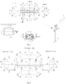
- a heat source-free optic fiber positioning and orienting system for monitoring seepage of submerged or partially submerged structures of the present invention includes a plurality of seepage monitoring devices connected through rotary supports, wherein the seepage monitoring devices include first seepage monitoring units symmetrically distributed on the front and back and second seepage monitoring units symmetrically distributed on left and right.
- the first seepage monitoring unit includes a first fiber-carrying recess 611 for fixing a monitoring fiber unit, the outside of the first fiber-carrying recess 611 is provided with a fiber-carrying protection layer 610, the two ends of the first fiber-carrying recess 611 are respectively provided with a left fiber-carrying end 600 and a right fiber-carrying end 603, the left fiber-carrying end 600 is connected to a left connecting ball 602 through a left connecting handle 601, the right fiber-carrying end 603 is connected to a right connecting ball 605 through a right connecting handle 604, the left connecting ball 602 and the right connecting ball 605 are hinged at the two ends of a cross beam support, and the cross beam support is extended with a left pin shaft 607 and a right pin shaft 609 towards the left and right sides.
- the second seepage monitoring unit includes a second fiber-carrying recess 504 for fixing the monitoring fiber unit, the two ends of the second fiber-carrying recess 504 are respectively provided with an upper fiber-carrying arc end 505 and a lower fiber-carrying arc end 503, the upper fiber-carrying arc end 505 is connected to an upper connecting shaft ball 507 through an upper arc connecting handle 506, the lower fiber-carrying arc end 503 is connected to a lower connecting shaft ball 501 through a lower arc connecting handle 502, the two ends of the gable end beam 509 are extended with an upper cross breaking beam 508 and a lower cross breaking beam 500, the upper connecting shaft ball 507 and the lower connecting shaft ball 501 are hinged on the upper cross breaking beam 508 and the lower cross breaking beam 500, the gable end beam 509 is extended with a gable convex column 511, and the inside of the gable convex column 511 is provided with conical holes 510 matched with the left pin shaft
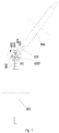
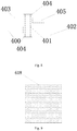
- the rotary support includes a first supporting framework column 301 and a second supporting framework column 304, one end of the first supporting framework column 301 is connected to the cross beam support and the other end is connected to a bottom circular turntable 402, and an upper circular turntable 403 is installed on the bottom circular turntable 402; one end of the second supporting framework column 304 is connected to the cross beam support of another seepage monitoring device and the other end is inserted into the upper circular turntable 403; a penetrating vertical beam 401 is installed on the center of the bottom circular turntable 402 and the upper circular turntable 403, the first supporting framework column 301 and the second supporting framework 304 can respectively rotate around the penetrating vertical beam 401, and the upper and lower ends of the penetrating vertical beam 401 are provided with turntable circular grooves 404 to block the penetrating vertical beam 401.
- the cross beam support includes an upper horizontal cross beam 612 and a lower horizontal cross beam 615 connected to the upper horizontal cross beam 612, the two ends of the upper horizontal cross beam 612 and the lower horizontal cross beam 615 are respectively extended with a left framework beam 606 and a right framework beam 608, the left framework beams 606 and the right framework beams 608 of the upper horizontal cross beam 612 and the lower horizontal cross beam 615 are respectively hinged with the left connecting ball 602 and the right connecting ball 605, the middle parts of the upper horizontal cross beam 612 and the lower horizontal cross beam 615 are respectively provided with an upper end groove 613 and a lower end groove 616, the upper end groove 613 is connected to the first supporting framework column 301, and the lower end groove 616 is connected to the first supporting framework column 301 of another rotary support.
- the upper horizontal cross beam 612 is provided with a T-shaped cross beam clamping groove 614
- the lower horizontal cross beam 615 is provided with a cross beam lug boss moving along the T-shaped cross beam clamping groove 614.
- the monitoring fiber unit includes one piece of seepage monitoring fiber 118 and two pieces of calibrated fibers 108, the two pieces of calibrated fibers 108 are located at the two sides of the seepage monitoring fiber 118, the seepage monitoring fiber 118 and the two pieces of calibrated fibers 108 are fixed through filling packing in the recess, the outside of the seepage monitoring fiber 118 is sheathed with a hard steel ring 117, the calibrated fibers 108 are sheathed with an adiabatic interlayer 106 and a hard protection layer 107 from inside to outside in sequence, the outside of the seepage monitoring fiber 118 is provided with an upper concave edge inner layer 111, a left concave edge inner layer 102, a lower concave edge inner layer 113 and a right concave edge inner layer 105 which are connected in sequence, the outside of the upper concave edge inner layer 111 is provided with an upper concave edge middle layer 109 and an upper concave edge outer layer 110 in sequence, the outside of the
- the bottom end of the concave structure will collect probable seepage water body in perimeter regions very easily, amplify the effect of small seepages, and be matched with the dialysis bar at the bottom end, thus greatly improving the identifying capacity on weak seepage or primary seepage.
- the arc section structure will enlarge the staying time and contact area of the seepage water body in the seepage region on the seepage monitoring fiber 118 to the maximum, and have higher precision assurance effect on positioning the seepage position in the region for monitoring.
- the upper concave edge outer layer 110 has anti-seepage and anti-corrosion performances, and the upper concave edge middle layer 109 and the upper concave edge inner layer 111 having similar section shapes are designed to be closely connected to the upper concave edge outer layer.
- the three-layer concave design structure improves the intensity and toughness of the fiber specially used for seepage monitoring, and can play the roles of protecting internal structures and prolonging the service life and the like.
- the hard protection layer 107 is disposed outside the adiabatic interlayer 106, the inside of the adiabatic interlayer 106 is contacted with the calibrated fiber 108; when the seepage water body acts on the region for monitoring, the calibrated fiber under the effect of the adiabatic interlayer 106 is under a state that has no heat contact with the outside, and will be used as reference calibrated fiber, and second correction of the result of the reference calibrated fiber 108 may be conducted by another calibrated fiber which is disposed symmetrically, so that the objective accuracy of the reference standard can be ensured to the maximum.
- the left concave edge outer layer 100 and the right concave edge outer layer 103 are convex edge structures with opposite concave edge outer layers. This opposite corresponding design greatly increases the sectional area of the special fibers for seepage monitoring, and improves the contact and connection tightness of the monitoring device and the structure for monitoring, and enhances the cooperativity between the monitoring device and the structure for monitoring.
- one of the effects for disposing it into a structure respectively having three layers in left and right is to increase the thickness of the interlayer at the position of the calibrated fiber 108, and the strength and the toughness of the materials are constantly increased from inside to outside; therefore, not only the flexible transition connection between the interior of the interlayer and the calibrated fiber 108 is improved, but also the effect of resisting a larger external seepage water pressure is increased; the left concave edge outer layer 100 and the right concave edge outer layer 103 have erosion resistance performance, so that the long-term coexistence between the left concave edge outer layer and the right concave edge outer layer, and the seepage water body is improved; in a complicated environment that may be possibly doped by corrosive ions, it has better seepage monitoring efficacy.
- the two sides of the seepage monitoring fiber 118 are respectively connected to an upper dialysis bar 115 and a lower dialysis bar 116, the upper dialysis bar 115 traverses the hard steel ring 117, the upper concave edge inner layer 111, the upper concave edge middle layer 109 and the upper concave edge outer layer 110 in sequence so as to be contacted with an outside seepage water flow, and the lower dialysis bar 116 traverses the hard steel ring 117, the lower concave edge inner layer 113, the lower concave edge middle layer 112 and the lower concave edge outer layer 114 in sequence so as to be contacted with the outside seepage water flow.
- an excircle retaining wall 203 is installed outside the monitoring fiber unit, the excircle retaining wall 203 includes an upper-left excircle retaining wall, a lower-left excircle retaining wall, an upper-right excircle retaining wall and a lower-right excircle retaining wall, the upper-left excircle retaining wall, the lower-left excircle retaining wall, the upper-right excircle retaining wall and the lower-right excircle retaining wall form a concave-convex type fiber-carrying cavity 204, the monitoring fiber unit is located in the concave-convex type fiber-carrying cavity 204, the upper-left excircle retaining wall and the upper-right excircle retaining wall are tightly locked through an upper fiber-carrying buckle 200, the lower-left excircle retaining wall and the lower-right excircle retaining wall are tightly locked through a lower fiber-carrying buckle 205, the upper-left excircle retaining wall and the lower-left excircle retaining wall
- the approximate circular cross section of the excircle retaining wall 203 makes secondary supplement on the concave section of the concave-convex designed monitoring fiber unit, and composes the fiber special for seepage disposed inside into a structure the outer section of which is approximate to a circle, thus making up the possible defects existing in production, transportation and disposing brought by its unique structure.
- the excircle retaining wall 203 can be opened around the left circular swivel 201 and the right circular swivel 202.
- the concave-convex type fiber-carrying cavity 204 in the excircle retaining wall 203 can precisely embed the fiber special for seepage of the present invention into the concave-convex type fiber-carrying cavity 204.
- the upper fiber-carrying buckle 200 and the lower fiber-carrying buckle 205 on the top and bottom of the excircle retaining wall 203 firmly close the excircle retaining wall 203, and prevent the excircle retaining wall 203 from loosing or disturbance of other factors such as artificial disturbance from the outside.
- a cavity is designed between the excircle retaining 203 and the concave-convex type fiber-carrying cavity 204, which reserves space for probable use and operation.
- the first supporting framework column 301 is connected to the upper end groove 613 in the upper horizontal cross beam 612 or the lower end groove 616 in the lower horizontal cross beam, and the other end of the first supporting framework column 301 is connected to the bottom circular turntable 402; after a lower rotating screw end 302 is connected to the bottom turntable screw groove 400, the seepage monitoring device at one end can conduct 360-degree dead space-free free rotation with the seepage monitoring device at the other end around the penetrating vertical beam 401; one end of an upper rotating screw end 303 is connected to the second supporting framework column 304 at the corresponding side thereof, the other end of the upper rotating screw end 303 is connected to the upper turntable screw groove 405, and the upper rotating screw end can drive the seepage monitoring device connected through a connecting screw end at the corresponding side to conduct 360-degree dead space-free free rotation at the other side around the penetrating vertical beam 401; the upper circular turntable 403 and the bottom circular turntable 402 which are dislocated up and down can realize the noninterference
- a seepage wire screen 618 is installed on the inner surface of the second fiber-carrying recess 504, and the surface of the seepage wire screen 618 is alveolar.
- both the left pin shaft 607 and the right pin shaft 609 are provided with a circular arc recess
- the upper surface of the gable convex column 511 is provided with a pin hole
- a pin is inserted into the pin hole
- the left pin shaft 607 and the right pin shaft 609 are fixed by inserting the pin into the circular arc recess.
- a monitoring method for a heat source-free optic fiber positioning and orienting system for monitoring seepage of submerged or partially submerged structures includes the following steps of: first step: determining the number of seepage monitoring devices according to the disposing requirements of a region for seepage monitoring, wherein six seepage monitoring devices are preliminarily determined based on the region for seepage monitoring, preparing 72 pieces of basic single mode bare fibers, and manufacturing the bare fibers into 24 monitoring fiber units with fixed length based on the basic structures of the seepage monitoring fiber units; second step: opening an upper-left excircle retaining wall, a lower-left excircle retaining wall, an upper-right excircle retaining wall and a lower-right excircle retaining wall around a left circular swivel 201 and a right circular swivel 202, disposing the monitoring fiber units in a concave-convex type fiber-carrying cavity 204, then rotating the left circular swivel 201 and the right circular swivel 202 to fold
- Table 2 Demodulating Information value of Seepage Monitoring Fiber Position Tag Demodulati ng temperature (°C) Absolute value of the difference between the demodulating temperature and the temperature of the calibrated fiber (°C) Seepage monitoring fiber of first seepage unit in the front end Ts9 10.00 0.59 Seepage monitoring fiber of first seepage unit in the rear end Ts10 10.90 0.31 Seepage monitoring fiber of second seepage unit in the left end Ts11 7.20 3.39 Seepage monitoring fiber of second seepage unit in the right end Ts12 10.10 0.49
- the detailed comparison result with that of the calibrated fibers in the eighth step is as seen in the last list of Table 2; at the moment and in the monitoring distance range, the situation of apparently larger value occurs in the seepage monitoring fibers of the second seepage unit in the left end, representing that a seepage problem may possibly exist, and the seepage position is in the left side direction; further, an absolute curve of the difference of the demodulating temperature
Landscapes
- Physics & Mathematics (AREA)
- General Physics & Mathematics (AREA)
- Life Sciences & Earth Sciences (AREA)
- General Life Sciences & Earth Sciences (AREA)
- Geophysics (AREA)
- Fluid Mechanics (AREA)
- Geophysics And Detection Of Objects (AREA)
- Light Guides In General And Applications Therefor (AREA)
- Testing Or Calibration Of Command Recording Devices (AREA)
- Examining Or Testing Airtightness (AREA)
- Testing Of Optical Devices Or Fibers (AREA)
Claims (9)
- Positionierungs- und Ausrichtungssystem einer wärmequellenfreien optischen Faser zum Überwachen der Durchsickerung von getauchten oder teilweise getauchten Strukturen, umfassend eine Vielzahl von Durchsickerungsüberwachungsvorrichtungen, die über drehbare Halterungen verbunden sind, wobei die Durchsickerungsüberwachungsvorrichtungen erste Durchsickerungsüberwachungseinheiten, die auf der Vorder- und Rückseite symmetrisch verteilt sind, und zweite Durchsickerungsüberwachungseinheiten, die links und rechts symmetrisch verteilt sind, umfassen;
die erste Durchsickerungsüberwachungseinheit eine erste fasertragende Ausnehmung (611) zum Befestigen einer Überwachungsfasereinheit umfasst, die Außenseite der ersten fasertragenden Ausnehmung mit einer fasertragenden Schutzschicht (610) versehen ist, die beiden Enden der ersten fasertragenden Ausnehmungen jeweils mit einem linken fasertragenden Ende (600) und einem rechten fasertragenden Ende (603) versehen sind, das linke fasertragende Ende über einen linken Verbindungsgriff (601) mit einer linken Verbindungskugel (602) verbunden ist, das rechte fasertragende Ende über einen rechten Verbindungsgriff(604) mit einer rechten Verbindungskugel (605) verbunden ist, die linke Verbindungskugel und die rechte Verbindungskugel an den beiden Enden eines Querträgers gelenkig verbunden sind, der Querträger mit einem linken Stiftschaft (607) und einem rechten Stiftschaft (609) zu der linken und der rechten Seite hin verlängert ist und das System ferner eine jeweilige erste und zweite Überwachungsfasereinheit umfasst, die jeweils in der ersten und der zweiten fasertragenden Ausnehmung befestigt ist und die Überwachungsfasereinheiten mit einer Informationserfassungsvorrichtung verbunden werden können; die zweite Durchsickerungsüberwachungseinheit eine zweite fasertragende Ausnehmung (504) zum Befestigen der Überwachungsfasereinheit umfasst, die beiden Enden der zweiten fasertragenden Ausnehmung jeweils mit einem oberen fasertragenden Bogenende (505) und einem unteren fasertragenden Bogenende versehen sind. das obere fasertragende Bogenende über einen oberen Bogenverbindungsgriff mit einer oberen Verbindungswellenkugel (506) verbunden ist, das untere fasertragende Bogenende über einen unteren Bogenverbindungsgriff (502) mit einer unteren Verbindungswellenkugel (501) verbunden ist, die obere Verbindungswellenkugel und die untere Verbindungswellenkugel an den beiden Enden eines Giebelendträgers (509) gelenkig verbunden sind, der Giebelendträger mit einer giebelkonvexen Säule (511) verlängert ist und die Innenseite der giebelkonvexen Säule mit konischen Löchern (510) versehen ist, die an den linken Stiftschaft und den rechten Stiftschaft angepasst sind; und
die drehbare Halterung eine erste Tragwerksäule (301) und eine zweite Tragwerksäule (304) umfasst, ein Ende der ersten Tragwerksäule mit dem Querträger verbunden ist und das andere Ende mit einer unteren kreisförmigen Drehscheibe (402) verbunden ist, und eine obere kreisförmige Drehscheibe (403) auf der unteren kreisförmigen Drehscheibe installiert ist; ein Ende der zweiten Tragwerksäule mit dem Querträger der anderen Durchsickerungsüberwachungsvorrichtung verbunden ist und das andere Ende in die obere kreisförmige Drehscheibe eingesetzt ist; eindringende Vertikalträger (401) in den Mitten der unteren kreisförmigen Drehscheibe und der oberen kreisförmigen Drehscheibe installiert sind, die erste Tragwerksäule und das zweite Tragwerk jeweils um den eindringenden Vertikalträger rotieren können und das obere und das untere Ende des eindringenden Vertikalträgers mit kreisförmigen Nuten der Drehscheibe versehen sind, die ausgestaltet sind, um den eindringenden Vertikalträger zu blockieren. - Positionierungs- und Ausrichtungssystem einer wärmequellenfreien optischen Faser zum Überwachen der Durchsickerung von getauchten oder teilweise getauchten Strukturen nach Anspruch 1, wobei der Querträger einen oberen horizontalen Querträger (612) und einen unteren horizontalen Querträger (615), der mit dem oberen horizontalen Querträger verbunden ist, umfasst, die beiden Enden des oberen horizontalen Querträgers und des unteren horizontalen Querträgers jeweils mit einem linken Rahmenträger (606) und einem rechten Rahmenträger (608) verlängert sind, die linken Rahmenträger und die rechten Rahmenträger des oberen horizontalen Querträgers und des unteren horizontalen Querträgers jeweils mit der linken Verbindungskugel und der rechten Verbindungskugel gelenkig verbunden sind, die mittleren Teile des oberen horizontalen Querträgers und des unteren horizontalen Querträgers jeweils mit einer Nut am oberen Ende (613) und einer Nut am unteren Ende (616) versehen sind, die Nut am oberen Ende mit der ersten Tragwerksäule verbunden ist, und die Nut am unteren Ende mit der ersten Tragwerksäule einer anderen drehbaren Halterung verbunden ist.
- Positionierungs- und Ausrichtungssystem einer wärmequellenfreien optischen Faser zum Überwachen der Durchsickerung von getauchten oder teilweise getauchten Strukturen nach Anspruch 2, wobei der obere horizontale Querträger mit einer T-förmigen Querträger-Klemmnut (614) versehen ist und der untere horizontale Querträger mit einem Querträger-Ansatzvorsprung versehen ist, um sich entlang der T-förmigen Querträger-Klemmnut zu bewegen.
- Positionierungs- und Ausrichtungssystem einer wärmequellenfreien optischen Faser zum Überwachen der Durchsickerung von getauchten oder teilweise getauchten Strukturen nach Anspruch 1, wobei die Überwachungsfasereinheit ein Teil einer Durchsickerungsüberwachungsfaser und zwei Teile kalibrierter Fasern (108) umfasst, die beiden Teile kalibrierter Fasern sich an den beiden Seiten der Durchsickerungsüberwachungsfaser befinden, die Außenseite der Durchsickerungsüberwachungsfaser mit einem harten Stahlring (117) ummantelt ist, die kalibrierten Fasern mit einer adiabatischen Zwischenschicht (106) und einer harten Schutzschicht (107) aufeinanderfolgend von innen nach außen ummantelt sind, die Außenseite der Durchsickerungsüberwachungsfaser mit einer inneren Schicht mit einer oberen konkaven Kante (111), einer inneren Schicht einer linken konkaven Kante (102) einer inneren Schicht mit einer unteren konkaven Kante (113) und einer inneren Schicht mit einer rechten konkaven Kante (105), die der Reihe nach verbunden sind, versehen ist, die Außenseite der inneren Schicht mit einer oberen konkaven Kante nacheinander mit einer mittleren Schicht mit einer oberen konkaven Kante und einer äußeren Schicht mit einer oberen konkaven Kante versehen ist, die Außenseite der inneren Schicht mit einer linken konkaven Kante nacheinander mit einer mittleren Schicht mit einer linken konkaven Kante und einer äußeren Schicht mit einer linken konkaven Kante (100) versehen ist, die Außenseite der inneren Schicht mit einer unteren konkaven Kante nacheinander mit einer mittleren Schicht mit einer unteren konkaven Kante und einer äußeren Schicht mit einer unteren konkaven Kante (114) versehen ist und die Außenseite der inneren Schicht mit einer rechten konkaven Kante nacheinander mit einer mittleren Schicht mit einer rechten konkaven Kante und einer äußeren Schicht mit einer rechten konkaven Kante (103) versehen ist,
- Positionierungs- und Ausrichtungssystem einer wärmequellenfreien optischen Faser zum Überwachen der Durchsickerung von getauchten oder teilweise getauchten Strukturen nach Anspruch 4, wobei die beiden Seiten der Durchsickerungsüberwachungsfaser (118) jeweils mit einer oberen Dialysestange (115) und einer unteren Dialysestange (116) verbunden sind, die obere Dialysestange nacheinander den harten Stahlring, die innere Schicht mit einer oberen konkaven Kante, die mittlere Schicht mit einer oberen konkaven Kante (109) und die äußere Schicht mit einer oberen konkaven Kante (110) durchquert, um mit einer äußeren Sickerwasserströmung in Kontakt zu geraten, und die untere Dialysestange nacheinander den harten Stahlring, die innere Schicht mit einer unteren konkaven Kante, die mittlere Schicht mit einer unteren konkaven Kante und die äußere Schicht mit einer unteren konkaven Kante durchquert, um mit der äußeren Sickerwasserströmung in Kontakt zu geraten.
- Positionierungs- und Ausrichtungssystem einer wärmequellenfreien optischen Faser zum Überwachen der Durchsickerung von getauchten oder teilweise getauchten Strukturen nach Anspruch 5, wobei eine Ankreis-Stützwand (203) außerhalb der Überwachungsfasereinheit installiert ist, die Ankreis-Stützwand eine Stützwand mit einem Ankreis links oben, eine Stützwand mit einem Ankreis links unten, eine Stützwand mit einem Ankreis rechts oben und eine Stützwand mit einem Ankreis rechts unten umfasst, die Stützwand mit einem Ankreis links oben, die Stützwand mit einem Ankreis links unten, die Stützwand mit einem Ankreis rechts oben und die Stützwand mit einem Ankreis rechts unten einen konkav-konvexartigen fasertragenden Hohlraum (204) bilden, die Überwachungsfasereinheit sich in dem konkav-konvexartigen fasertragenden Hohlraum befindet, die Stützwand mit einem Ankreis links oben und die Stützwand mit einem Ankreis rechts oben durch einen oberen fasertragenden Verschluss (200) fest verschlossen sind, die Stützwand mit einem Ankreis links unten und die Stützwand mit einem Ankreis rechts unten durch einen unteren fasertragenden Verschluss (205) fest verschlossen sind, die Stützwand mit einem Ankreis links oben und die Stützwand mit einem Ankreis links unten jeweils um ein linkes kreisförmiges Drehgelenk (201) rotieren und die Stützwand mit einem Ankreis rechts oben und die Stützwand mit einem Ankreis rechts unten jeweils um ein rechtes kreisförmiges Drehgelenk rotieren.
- Positionierungs- und Ausrichtungssystem einer wärmequellenfreien optischen Faser zum Überwachen der Durchsickerung von getauchten oder teilweise getauchten Strukturen nach Anspruch 1, wobei ein Durchsickerungsdrahtgitter (618) auf der Innenfläche der zweiten fasertragenden Ausnehmung installiert ist und die Fläche des Durchsickerungsdrahtgitters alveolar ist.
- Positionierungs- und Ausrichtungssystem einer wärmequellenfreien optischen Faser zum Überwachen der Durchsickerung von getauchten oder teilweise getauchten Strukturen nach Anspruch 1, wobei sowohl der linke Stiftschaft als auch der rechte Stiftschaft mit einer kreisförmigen Bogenausnehmung versehen sind, die obere Fläche der giebelkonvexen Säule mit einem Stiftloch versehen ist, ein Stift in das Stiftloch eingesetzt ist und der linke Stiftschaft und der rechte Stiftschaft durch Einsetzen des Stifts in die kreisförmige Bogenausnehmung befestigt sind.
- Überwachungsverfahren zum Überwachen der Durchsickerung von getauchten oder teilweise getauchten Strukturen durch ein Positionierung- und Ausrichtungssystem einer wärmequellenfreien optischen Faser, das die folgenden Schritte umfasst:erster Schritt: Vorbereiten einer Vielzahl von Teilen von grundlegenden blanken Monomode-Fasern und Herstellen der blanken Fasern zu einer Vielzahl von Teilen aus Überwachungsfasereinheiten mit festen Längen, basierend auf den Strukturen einer ersten Durchsickerungsüberwachungseinheit und einer zweiten Durchsickerungsüberwachungseinheit;zweiter Schritt: Öffnen einer Stützwand mit einem Ankreis links oben, einer Stützwand mit einem Ankreis links unten, einer Stützwand mit einem Ankreis rechts oben und einer Stützwand mit einem Ankreis rechts unten um ein linkes kreisförmiges Drehgelenk und um ein rechtes kreisförmiges Drehgelenk (202) herum, Anordnen der Überwachungsfasereinheiten in einem konkav-konvexartigen fasertragenden Hohlraum, dann Rotieren des linken kreisförmigen Drehgelenks und des rechten kreisförmigen Drehgelenks, um die Stützwand mit einem Ankreis links oben, die Stützwand mit einem Ankreis links unten, die Stützwand mit einem Ankreis rechts oben und die Stützwand mit einem Ankreis rechts unten zusammenzulegen, Verwenden eines oberen fasertragenden Verschlusses und eines unteren fasertragenden Verschlusses, um die Stützwand mit einem Ankreis links oben, die Stützwand mit einem Ankreis links unten, die Stützwand mit einem Ankreis rechts oben und die Stützwand mit einem Ankreis rechts unten, die an den beiden Enden verteilt sind, zu wölben, dann Wickeln der Überwachungsfasereinheiten auf einem Walzrad der Überwachungsfasereinheit und Transportieren der Überwachungsfasereinheit in eine Position zur Durchsickerungsüberwachung;dritter Schritt: Anpassen einer Querträger-Klemmnut auf einem oberen horizontalen Querträger, geradliniges Gleiten einer konvexen Querträgernut (617) in einem unteren horizontalen Querträger entlang der Querträger-Klemmnut und schließlich paralleles Zusammenschrauben und Anordnen des oberen horizontalen Querträgers und des unteren horizontalen Querträgers, dann Abschrauben der linken Stiftschafte, die symmetrisch oben und unten auf der linken Seite des Querträgers verteilt sind, Einsetzen der linken Stiftschafte in konische Löcher in einer konvexen Giebelsäule eines Giebelendträgers auf der linken Seite des Querträgers, dann Einsetzen von Stiften in Stiftlöcher, um die linken Stiftschafte zu befestigen und ebenso Abschrauben der rechten Stiftschafte, die symmetrisch oben und unten auf der rechten Seite des Querträgers verteilt sind, Einsetzen der rechten Stiftschafte in konische Löcher in einer konvexen Giebelsäule eines Giebelendträgers auf der rechten Seite des Querträgers, dann Einsetzen von Stiften in Stiftlöcher, um die rechten Stiftschafte zu befestigen;vierter Schritt: nach dem Transportieren der Überwachungsfasereinheiten in einen Bereich zum Überwachen, Abschrauben des oberen fasertragenden Verschlusses und des unteren fasertragenden Verschlusses, Öffnen der Stützwand mit einem Ankreis links oben, der Stützwand mit einem Ankreis links unten, der Stützwand mit einem Ankreis rechts oben und der Stützwand mit einem Ankreis rechts unten, um die Überwachungsfasereinheiten aus dem konkav-konvexartigen fasertragenden Hohlraum zu entnehmen, Anordnen einer Überwachungsfasereinheit mit fester Länge in einer zweiten fasertragenden Ausnehmung der zweiten Durchsickerungsüberwachungseinheit, deren beide Enden symmetrisch verteilt sind und deren innere Wand mit einem Durchsickerungsdrahtgitter (618) versehen ist, und Anordnen einer weiteren Überwachungsfasereinheit mit fester Länge in einer ersten fasertragenden Ausnehmung (611) der ersten Durchsickerungsüberwachungseinheit, deren innere Wand mit einem Durchsickerungsdrahtgitter versehen ist; gelenkiges Verbinden der zweiten fasertragenden Ausnehmung, die mit einer unteren Verbindungswellenkugel, einem unteren fasertragenden Bogenende (503), einer oberen Verbindungswellenkugel und einem oberen fasertragenden Bogenende versehen ist, mit den beiden Enden eines Giebelendträgers (509) über eine untere Verbindungswellenkugel und eine obere Verbindungswellenkugel (507) auf der linken Seite, und ebenso gelenkiges Verbinden der zweiten fasertragenden Ausnehmung, die mit der unteren Verbindungswellenkugel, dem unteren fasertragenden Bogenende, der oberen Verbindungswellenkugel und dem oberen fasertragenden Bogenende versehen ist, mit den beiden Enden des Giebelendträgers über eine untere Verbindungswellenkugel und eine obere Verbindungswellenkugel auf der rechten Seite;fünfter Schritt: gelenkiges Verbinden einer ersten fasertragenden Ausnehmung, die mit einem linken fasertragenden Ende, einem linken Verbindungsgriff sowie einem rechten fasertragenden Ende und einem rechten Verbindungsgriff verbunden ist, mit einem linken Rahmenträger und einem rechten Rahmenträger über eine linke Verbindungswellenkugel und eine rechte Verbindungswellenkugel an dem oberen Ende, und ebenso gelenkiges Verbinden der ersten fasertragenden Ausnehmung, die mit dem linken fasertragenden Ende, dem linken Verbindungsgriff und dem rechten fasertragenden Ende und dem rechten Verbindungsgriff verbunden ist, mit dem linken Rahmenträger und dem rechten Rahmenträger über eine linke Verbindungswellenkugel und eine rechte Verbindungswellenkugel an dem unteren Ende, somit Beenden des Anordnens der Durchsickerungsüberwachungsvorrichtungen am Startende davon;sechster Schritt: Einsetzen eines Endes der ersten Tragwerksäule in eine Nut am oberen Ende in dem oberen horizontalen Querträger, Anordnen des anderen Endes der ersten Tragwerksäule in eine Schraubnut der unteren Drehscheibe (400), Einsetzen von einem Ende einer zweiten Tragwerksäule in eine Schraubnut der oberen Drehscheibe (405), Zusammendrücken eines eindringenden Vertikalträgers und Anordnen von kreisförmigen Nuten der Drehscheibe (404) an dem oberen und dem unteren Ende des eindringenden Vertikalträgers, um den eindringenden Vertikalträger vollständig zu blockieren, Verbinden des anderen Endes der zweiten Tragwerksäule mit einer Querträger-Klemmnut in einem oberen horizontalen Querträger einer weiteren Durchsickerungsüberwachungsvorrichtung, Rotieren der ersten Tragwerksäule unter der zweiten Tragwerksäule nach oben und nach unten um den eindringenden Vertikalträger herum, um die Anordnungsformate der ersten und der zweiten Tragwerksäule anzupassen, sodass sie wirksam an eine Struktur zum Überwachen in einem Bereich zur Durchsickerungsüberwachung angepasst sind, Anordnen von unteren horizontalen Querträgern (615) von zwei Durchsickerungsüberwachungsvorrichtungen in dem gleichen Schritt wie oben, um verschiedene Durchsickerungsüberwachungsvorrichtungen über eine weitere neue drehbare Halterung in Reihe zu verbinden, Anpassen der Drehrichtung der Tragwerksäule (301), um das Anordnen der Durchsickerungsüberwachungsvorrichtungen am Fußende abzuschließen, und Verbinden der kalibrierten Fasern (108) und der Durchsickerungsüberwachungsfasern in sämtlichen Durchsickerungsüberwachungsvorrichtungen mit einer Informationserfassungsvorrichtung,siebter Schritt: Öffnen der Informationserfassungsvorrichtung, zuerst Erfassen der Informationen der kalibrierten Fasern, Entfernen der Fasern darin, die eine größere Differenz zum Mittelwert aufweisen, und Reservieren einiger Teile von kalibrierten Fasern mit minimalen Temperaturveränderungen, und Annehmen der kalibrierten Fasern, die einer gegenseitigen Korrektur unterworfen werden, als endgültige kalibrierte Fasern; undachter Schritt: nachdem ein Sickerwasserkörper den Bereich passiert hat, direktes Übertragen der Wärme des Sickerwasserkörpers in die Position der Durchsickerungsüberwachungsfasern über eine obere Dialysestange und eine untere Dialysestange, Aufzeichnen der Veränderungssituationen der Durchsickerungsüberwachungsfasern in Echtzeit, Vergleichen der Durchsickerungsüberwachungsfasern mit den kalibrierten Fasern in dem siebten Schritt zwecks Analyse und Identifizieren der Durchsickerungsbedingung der Position; wenn der Sickerwasserkörper der getauchten oder teilweise getauchten Strukturen durch die Durchsickerungsüberwachungsvorrichtung strömt, Erfassen des passierten Wasserkörpers über die erste fasertragende Ausnehmung und die zweite fasertragende Ausnehmung (504) in einer ersten Überwachungsfasereinheit und einer zweiten Überwachungsfasereinheit, Aufzeichnen von Daten, die von der Datenerfassungsvorrichtung in Echtzeit erfasst werden, Differenzieren des Wertes des Datenwertes mit dem Wert der kalibrierten Fasern, Zeichnen eines Differenzierungsergebnisses in eine Zeit-Weg-Kurve und Ermitteln, dass der Sickerwasserkörper in der Position darstellt, wenn die Zeit-Weg-Kurve sich stark verändert, somit Feststellen der Positionierung; über dasselbe Verfahren wie oben, Analysieren der Zeit-Weg-Kurven der Überwachungsfasereinheit, die in verschiedenen Richtungen in den Durchsickerungsüberwachungsvorrichtungen angeordnet ist, und Ermitteln, dass der Sickerwasserkörper in einer bestimmten Richtung darstellt, wenn die Zeit-Weg-Kurve der Überwachungsfasern in der Richtung stark schwankt, somit Feststellen der Positionierung; und dadurch Durchführen der Durchsickerungspositionierungs- undausrichtungsüberwachung der getauchten oder teilweise getauchten Strukturen.
Applications Claiming Priority (2)
| Application Number | Priority Date | Filing Date | Title |
|---|---|---|---|
| CN201410833964.4A CN104570148B (zh) | 2014-12-29 | 2014-12-29 | 涉水结构物渗漏无热源光纤定位定向系统及监测方法 |
| PCT/CN2014/095610 WO2016106572A1 (zh) | 2014-12-29 | 2014-12-30 | 涉水结构物渗漏无热源光纤定位定向系统及监测方法 |
Publications (3)
| Publication Number | Publication Date |
|---|---|
| EP3062129A1 EP3062129A1 (de) | 2016-08-31 |
| EP3062129A4 EP3062129A4 (de) | 2017-08-09 |
| EP3062129B1 true EP3062129B1 (de) | 2018-12-05 |
Family
ID=53086662
Family Applications (1)
| Application Number | Title | Priority Date | Filing Date |
|---|---|---|---|
| EP14889181.5A Active EP3062129B1 (de) | 2014-12-29 | 2014-12-30 | System und verfahren ohne wärmequelle für glasfaserpositionierung - und orientierung zur leckdetektion einer eingetauchten struktur |
Country Status (7)
| Country | Link |
|---|---|
| US (1) | US10012760B2 (de) |
| EP (1) | EP3062129B1 (de) |
| JP (1) | JP6190081B2 (de) |
| CN (1) | CN104570148B (de) |
| AU (1) | AU2014392219B2 (de) |
| CA (1) | CA2909644C (de) |
| WO (1) | WO2016106572A1 (de) |
Cited By (1)
| Publication number | Priority date | Publication date | Assignee | Title |
|---|---|---|---|---|
| CN112187348A (zh) * | 2020-10-15 | 2021-01-05 | 郭天强 | 一种用于光时域反射仪便携式携带箱 |
Families Citing this family (7)
| Publication number | Priority date | Publication date | Assignee | Title |
|---|---|---|---|---|
| IL292225B2 (en) * | 2014-09-17 | 2024-12-01 | Intra Cellular Therapies Inc | Derivatives of 5,7,7-trimethyl-[2H]-imidazo-[1,2-a]pyrazolo[4,3-e]pyrimidin-4(5H)-one and pharmaceutical compositions comprising them. |
| CN105181362B (zh) * | 2015-06-19 | 2016-04-13 | 河海大学 | 水工建筑物渗流性态分布式光纤感知集成系统与方法 |
| CN104977673B (zh) * | 2015-06-19 | 2016-03-02 | 河海大学 | 一种水工测渗用自控热源特制单模光纤 |
| CN105223667B (zh) * | 2015-11-16 | 2018-08-24 | 南京陶特思软件科技有限公司 | 一种新型直埋加热测温光缆 |
| CN105716686B (zh) * | 2016-02-19 | 2017-11-24 | 河海大学 | 复杂环境下堤坝浸润线分布式光纤感知系统及运行方法 |
| CN105738147B (zh) * | 2016-05-05 | 2018-03-20 | 河海大学 | 一种水工程渗流性态融合感知系统 |
| CN114779421B (zh) * | 2022-06-22 | 2022-09-30 | 长飞光纤光缆股份有限公司 | 一种防热冲击耐高压光缆 |
Family Cites Families (17)
| Publication number | Priority date | Publication date | Assignee | Title |
|---|---|---|---|---|
| JPH0674768A (ja) * | 1992-08-25 | 1994-03-18 | Oyo Corp | 河床洗掘監視方法 |
| JP2612812B2 (ja) * | 1993-06-17 | 1997-05-21 | 三井金属鉱業株式会社 | 地層中の水分挙動/物質移行の測定システム及びその探査方法 |
| US5663490A (en) * | 1995-04-14 | 1997-09-02 | Daito Kogyo Co., Ltd. | Breakage detection system for water-barrier sheet in waste disposal facility |
| US20040043501A1 (en) * | 1997-05-02 | 2004-03-04 | Baker Hughes Incorporated | Monitoring of downhole parameters and chemical injection utilizing fiber optics |
| JP2002515597A (ja) * | 1998-05-15 | 2002-05-28 | ゲゾ ゲゼルシャフト フュール ゼンゾーリク,ゲオテクニシェン ウムヴェルトシュツ ウント マテマーティシェ モデリールンク エムベーハー イェナ | 温度分布および/または温度異常を分散形光ファイバー温度検知に基づいて永久的かつ自動的に監視するための方法および装置、およびその方法の用途 |
| US6993437B1 (en) | 2004-03-02 | 2006-01-31 | The United States Of America As Represented By The Secretary Of The Navy | Tidal seepage meter |
| DE202004013034U1 (de) | 2004-08-20 | 2006-01-19 | Siggelkow, Jens | Sensor für Auslösesysteme von maritimen Rettungsgeräten |
| JP2007139628A (ja) * | 2005-11-21 | 2007-06-07 | Occ Corp | 光ファイバ水位計測システム及び光ファイバ水位計測方法 |
| FR2903773B1 (fr) * | 2006-07-13 | 2009-05-08 | Bidim Geosynthetics Soc Par Ac | Dispositif, systeme et procede de detection et de localisation de dysfonctionnement dans un ouvrage hydraulique, ainsi qu'un ouvrage hydraulique equipe de ce dispositif. |
| WO2009114722A2 (en) | 2008-03-12 | 2009-09-17 | Woods Hole Oceanographic Institution | Systems and methods for intercepting submarine groundwater for desalination |
| CN201322679Y (zh) * | 2008-10-27 | 2009-10-07 | 中芯国际集成电路制造(上海)有限公司 | 化学品供应泵的泄漏检测系统 |
| CN102128709B (zh) * | 2010-01-15 | 2013-05-01 | 张移生 | 新型预制管件抗渗检验接口及使用该接口的抗渗性能检测方法 |
| US8881576B2 (en) * | 2010-04-09 | 2014-11-11 | Inficon Gmbh | Test device for performing leak detection at a plurality of test sites |
| CN102720949B (zh) * | 2012-06-11 | 2013-08-14 | 天津大学 | 一种光纤管道泄漏监测装置及其控制方法 |
| CN103364321B (zh) * | 2013-07-19 | 2015-04-22 | 河海大学 | 一种监测土石堤坝渗流状况的分布式光纤测试平台 |
| CN103364320B (zh) * | 2013-07-19 | 2016-04-13 | 河海大学 | 多孔介质结构体渗流的分布式光纤测试方法 |
| CN204287517U (zh) * | 2014-12-29 | 2015-04-22 | 河海大学 | 涉水结构物渗漏无热源光纤定位定向系统 |
-
2014
- 2014-12-29 CN CN201410833964.4A patent/CN104570148B/zh active Active
- 2014-12-30 WO PCT/CN2014/095610 patent/WO2016106572A1/zh not_active Ceased
- 2014-12-30 AU AU2014392219A patent/AU2014392219B2/en active Active
- 2014-12-30 JP JP2016567110A patent/JP6190081B2/ja active Active
- 2014-12-30 EP EP14889181.5A patent/EP3062129B1/de active Active
- 2014-12-30 CA CA2909644A patent/CA2909644C/en active Active
- 2014-12-30 US US14/890,501 patent/US10012760B2/en active Active
Non-Patent Citations (1)
| Title |
|---|
| None * |
Cited By (2)
| Publication number | Priority date | Publication date | Assignee | Title |
|---|---|---|---|---|
| CN112187348A (zh) * | 2020-10-15 | 2021-01-05 | 郭天强 | 一种用于光时域反射仪便携式携带箱 |
| CN112187348B (zh) * | 2020-10-15 | 2021-08-27 | 郭天强 | 一种用于光时域反射仪便携式携带箱 |
Also Published As
| Publication number | Publication date |
|---|---|
| US10012760B2 (en) | 2018-07-03 |
| JP6190081B2 (ja) | 2017-08-30 |
| US20160356918A1 (en) | 2016-12-08 |
| WO2016106572A1 (zh) | 2016-07-07 |
| CN104570148B (zh) | 2015-09-02 |
| AU2014392219B2 (en) | 2016-10-13 |
| EP3062129A1 (de) | 2016-08-31 |
| JP2017506712A (ja) | 2017-03-09 |
| CA2909644A1 (en) | 2016-06-29 |
| EP3062129A4 (de) | 2017-08-09 |
| CN104570148A (zh) | 2015-04-29 |
| CA2909644C (en) | 2018-10-30 |
| AU2014392219A1 (en) | 2016-07-14 |
Similar Documents
| Publication | Publication Date | Title |
|---|---|---|
| US10012760B2 (en) | Heat source-free fiber positioning and orienting system for seepage of submerged or partially-submerged structures and monitoring method thereof | |
| CN104515653B (zh) | 一种监测水工结构体渗漏的装置及方法 | |
| CN104482331B (zh) | 一种智能rtp管及其制备方法 | |
| CN103821507B (zh) | 立井井壁变形分布式光纤检测方法 | |
| CN104280166B (zh) | 监测预警岩土体赋水及安全状态的导管组件 | |
| CN104389325A (zh) | 基坑围护墙全自动测斜系统及测斜方法 | |
| CN113933032A (zh) | 船闸人字门结构健康监测系统及故障诊断方法 | |
| CN108267250A (zh) | 一种基于光纤光栅传感器的盾构滚刀受力在线监测装置 | |
| CN204212184U (zh) | 基坑围护墙全自动测斜系统 | |
| KR102371714B1 (ko) | 로봇을 이용한 지중 케이블 이상상태 점검 시스템 | |
| CN204330232U (zh) | 一种监测水工结构体渗漏的装置 | |
| CN111076853A (zh) | 一种用于船舶结构应力监测的短基传感器及其使用方法 | |
| CN114960749A (zh) | 一种水下隧道变形缝内装可卸式止水带及实时监测方法 | |
| KR102822714B1 (ko) | 안전진단을 위한 시설물 와이어 손상 및 마모 측정 장치 | |
| CN220398476U (zh) | 一种分布式岩溶塌陷位移监测装置 | |
| CN206804938U (zh) | 一种自承重皮线光缆 | |
| CN205373914U (zh) | 一种用于油浸式变压器光纤监测的贯通器 | |
| CN211344464U (zh) | 一种具备监测管路泄漏功能的直埋式保温蒸汽管 | |
| CN218759823U (zh) | 一种多功能随钻测斜仪 | |
| CN221622171U (zh) | 一种污染场地便携式微扰动现场探测装置 | |
| CN118049907B (zh) | 一种航油地井用内外筒偏移量规及其偏移量检测方法 | |
| CN215448210U (zh) | 一种具有防护机构的温度传感器 | |
| CN119290220B (zh) | 一种载人潜水器观察窗应力状态监测装置 | |
| CN218626471U (zh) | 一种钢套钢直埋蒸汽管道监测系统 | |
| CN221507170U (zh) | 一种管线探测仪的探头快换结构 |
Legal Events
| Date | Code | Title | Description |
|---|---|---|---|
| PUAI | Public reference made under article 153(3) epc to a published international application that has entered the european phase |
Free format text: ORIGINAL CODE: 0009012 |
|
| 17P | Request for examination filed |
Effective date: 20151016 |
|
| AK | Designated contracting states |
Kind code of ref document: A1 Designated state(s): AL AT BE BG CH CY CZ DE DK EE ES FI FR GB GR HR HU IE IS IT LI LT LU LV MC MK MT NL NO PL PT RO RS SE SI SK SM TR |
|
| AX | Request for extension of the european patent |
Extension state: BA ME |
|
| A4 | Supplementary search report drawn up and despatched |
Effective date: 20170712 |
|
| RIC1 | Information provided on ipc code assigned before grant |
Ipc: G01K 11/32 20060101ALN20170706BHEP Ipc: G01V 8/02 20060101AFI20170706BHEP Ipc: G01D 11/30 20060101ALI20170706BHEP Ipc: G01D 5/353 20060101ALI20170706BHEP Ipc: G01K 1/14 20060101ALN20170706BHEP |
|
| DAX | Request for extension of the european patent (deleted) | ||
| REG | Reference to a national code |
Ref country code: DE Ref legal event code: R079 Ref document number: 602014037665 Country of ref document: DE Free format text: PREVIOUS MAIN CLASS: G01V0008100000 Ipc: G01V0008020000 |
|
| RIC1 | Information provided on ipc code assigned before grant |
Ipc: G01D 11/30 20060101ALN20180611BHEP Ipc: G01V 8/02 20060101AFI20180611BHEP Ipc: G01D 5/353 20060101ALN20180611BHEP |
|
| GRAP | Despatch of communication of intention to grant a patent |
Free format text: ORIGINAL CODE: EPIDOSNIGR1 |
|
| STAA | Information on the status of an ep patent application or granted ep patent |
Free format text: STATUS: GRANT OF PATENT IS INTENDED |
|
| INTG | Intention to grant announced |
Effective date: 20180727 |
|
| GRAS | Grant fee paid |
Free format text: ORIGINAL CODE: EPIDOSNIGR3 |
|
| GRAA | (expected) grant |
Free format text: ORIGINAL CODE: 0009210 |
|
| GRAA | (expected) grant |
Free format text: ORIGINAL CODE: 0009210 |
|
| STAA | Information on the status of an ep patent application or granted ep patent |
Free format text: STATUS: THE PATENT HAS BEEN GRANTED |
|
| AK | Designated contracting states |
Kind code of ref document: B1 Designated state(s): AL AT BE BG CH CY CZ DE DK EE ES FI FR GB GR HR HU IE IS IT LI LT LU LV MC MK MT NL NO PL PT RO RS SE SI SK SM TR |
|
| REG | Reference to a national code |
Ref country code: GB Ref legal event code: FG4D |
|
| REG | Reference to a national code |
Ref country code: CH Ref legal event code: EP |
|
| REG | Reference to a national code |
Ref country code: AT Ref legal event code: REF Ref document number: 1073772 Country of ref document: AT Kind code of ref document: T Effective date: 20181215 |
|
| REG | Reference to a national code |
Ref country code: IE Ref legal event code: FG4D |
|
| REG | Reference to a national code |
Ref country code: DE Ref legal event code: R096 Ref document number: 602014037665 Country of ref document: DE |
|
| REG | Reference to a national code |
Ref country code: NL Ref legal event code: MP Effective date: 20181205 |
|
| REG | Reference to a national code |
Ref country code: AT Ref legal event code: MK05 Ref document number: 1073772 Country of ref document: AT Kind code of ref document: T Effective date: 20181205 |
|
| REG | Reference to a national code |
Ref country code: LT Ref legal event code: MG4D |
|
| PG25 | Lapsed in a contracting state [announced via postgrant information from national office to epo] |
Ref country code: BG Free format text: LAPSE BECAUSE OF FAILURE TO SUBMIT A TRANSLATION OF THE DESCRIPTION OR TO PAY THE FEE WITHIN THE PRESCRIBED TIME-LIMIT Effective date: 20190305 Ref country code: HR Free format text: LAPSE BECAUSE OF FAILURE TO SUBMIT A TRANSLATION OF THE DESCRIPTION OR TO PAY THE FEE WITHIN THE PRESCRIBED TIME-LIMIT Effective date: 20181205 Ref country code: NO Free format text: LAPSE BECAUSE OF FAILURE TO SUBMIT A TRANSLATION OF THE DESCRIPTION OR TO PAY THE FEE WITHIN THE PRESCRIBED TIME-LIMIT Effective date: 20190305 Ref country code: LT Free format text: LAPSE BECAUSE OF FAILURE TO SUBMIT A TRANSLATION OF THE DESCRIPTION OR TO PAY THE FEE WITHIN THE PRESCRIBED TIME-LIMIT Effective date: 20181205 Ref country code: ES Free format text: LAPSE BECAUSE OF FAILURE TO SUBMIT A TRANSLATION OF THE DESCRIPTION OR TO PAY THE FEE WITHIN THE PRESCRIBED TIME-LIMIT Effective date: 20181205 Ref country code: AT Free format text: LAPSE BECAUSE OF FAILURE TO SUBMIT A TRANSLATION OF THE DESCRIPTION OR TO PAY THE FEE WITHIN THE PRESCRIBED TIME-LIMIT Effective date: 20181205 Ref country code: LV Free format text: LAPSE BECAUSE OF FAILURE TO SUBMIT A TRANSLATION OF THE DESCRIPTION OR TO PAY THE FEE WITHIN THE PRESCRIBED TIME-LIMIT Effective date: 20181205 Ref country code: FI Free format text: LAPSE BECAUSE OF FAILURE TO SUBMIT A TRANSLATION OF THE DESCRIPTION OR TO PAY THE FEE WITHIN THE PRESCRIBED TIME-LIMIT Effective date: 20181205 |
|
| PG25 | Lapsed in a contracting state [announced via postgrant information from national office to epo] |
Ref country code: AL Free format text: LAPSE BECAUSE OF FAILURE TO SUBMIT A TRANSLATION OF THE DESCRIPTION OR TO PAY THE FEE WITHIN THE PRESCRIBED TIME-LIMIT Effective date: 20181205 Ref country code: RS Free format text: LAPSE BECAUSE OF FAILURE TO SUBMIT A TRANSLATION OF THE DESCRIPTION OR TO PAY THE FEE WITHIN THE PRESCRIBED TIME-LIMIT Effective date: 20181205 Ref country code: SE Free format text: LAPSE BECAUSE OF FAILURE TO SUBMIT A TRANSLATION OF THE DESCRIPTION OR TO PAY THE FEE WITHIN THE PRESCRIBED TIME-LIMIT Effective date: 20181205 Ref country code: GR Free format text: LAPSE BECAUSE OF FAILURE TO SUBMIT A TRANSLATION OF THE DESCRIPTION OR TO PAY THE FEE WITHIN THE PRESCRIBED TIME-LIMIT Effective date: 20190306 |
|
| PG25 | Lapsed in a contracting state [announced via postgrant information from national office to epo] |
Ref country code: NL Free format text: LAPSE BECAUSE OF FAILURE TO SUBMIT A TRANSLATION OF THE DESCRIPTION OR TO PAY THE FEE WITHIN THE PRESCRIBED TIME-LIMIT Effective date: 20181205 |
|
| PG25 | Lapsed in a contracting state [announced via postgrant information from national office to epo] |
Ref country code: IT Free format text: LAPSE BECAUSE OF FAILURE TO SUBMIT A TRANSLATION OF THE DESCRIPTION OR TO PAY THE FEE WITHIN THE PRESCRIBED TIME-LIMIT Effective date: 20181205 Ref country code: PT Free format text: LAPSE BECAUSE OF FAILURE TO SUBMIT A TRANSLATION OF THE DESCRIPTION OR TO PAY THE FEE WITHIN THE PRESCRIBED TIME-LIMIT Effective date: 20190405 Ref country code: PL Free format text: LAPSE BECAUSE OF FAILURE TO SUBMIT A TRANSLATION OF THE DESCRIPTION OR TO PAY THE FEE WITHIN THE PRESCRIBED TIME-LIMIT Effective date: 20181205 Ref country code: CZ Free format text: LAPSE BECAUSE OF FAILURE TO SUBMIT A TRANSLATION OF THE DESCRIPTION OR TO PAY THE FEE WITHIN THE PRESCRIBED TIME-LIMIT Effective date: 20181205 |
|
| REG | Reference to a national code |
Ref country code: CH Ref legal event code: PL |
|
| PG25 | Lapsed in a contracting state [announced via postgrant information from national office to epo] |
Ref country code: LU Free format text: LAPSE BECAUSE OF NON-PAYMENT OF DUE FEES Effective date: 20181230 Ref country code: IS Free format text: LAPSE BECAUSE OF FAILURE TO SUBMIT A TRANSLATION OF THE DESCRIPTION OR TO PAY THE FEE WITHIN THE PRESCRIBED TIME-LIMIT Effective date: 20190405 Ref country code: RO Free format text: LAPSE BECAUSE OF FAILURE TO SUBMIT A TRANSLATION OF THE DESCRIPTION OR TO PAY THE FEE WITHIN THE PRESCRIBED TIME-LIMIT Effective date: 20181205 Ref country code: SK Free format text: LAPSE BECAUSE OF FAILURE TO SUBMIT A TRANSLATION OF THE DESCRIPTION OR TO PAY THE FEE WITHIN THE PRESCRIBED TIME-LIMIT Effective date: 20181205 Ref country code: EE Free format text: LAPSE BECAUSE OF FAILURE TO SUBMIT A TRANSLATION OF THE DESCRIPTION OR TO PAY THE FEE WITHIN THE PRESCRIBED TIME-LIMIT Effective date: 20181205 Ref country code: SM Free format text: LAPSE BECAUSE OF FAILURE TO SUBMIT A TRANSLATION OF THE DESCRIPTION OR TO PAY THE FEE WITHIN THE PRESCRIBED TIME-LIMIT Effective date: 20181205 |
|
| REG | Reference to a national code |
Ref country code: DE Ref legal event code: R097 Ref document number: 602014037665 Country of ref document: DE |
|
| REG | Reference to a national code |
Ref country code: BE Ref legal event code: MM Effective date: 20181231 Ref country code: IE Ref legal event code: MM4A |
|
| PLBE | No opposition filed within time limit |
Free format text: ORIGINAL CODE: 0009261 |
|
| STAA | Information on the status of an ep patent application or granted ep patent |
Free format text: STATUS: NO OPPOSITION FILED WITHIN TIME LIMIT |
|
| PG25 | Lapsed in a contracting state [announced via postgrant information from national office to epo] |
Ref country code: DK Free format text: LAPSE BECAUSE OF FAILURE TO SUBMIT A TRANSLATION OF THE DESCRIPTION OR TO PAY THE FEE WITHIN THE PRESCRIBED TIME-LIMIT Effective date: 20181205 Ref country code: IE Free format text: LAPSE BECAUSE OF NON-PAYMENT OF DUE FEES Effective date: 20181230 Ref country code: SI Free format text: LAPSE BECAUSE OF FAILURE TO SUBMIT A TRANSLATION OF THE DESCRIPTION OR TO PAY THE FEE WITHIN THE PRESCRIBED TIME-LIMIT Effective date: 20181205 Ref country code: MC Free format text: LAPSE BECAUSE OF FAILURE TO SUBMIT A TRANSLATION OF THE DESCRIPTION OR TO PAY THE FEE WITHIN THE PRESCRIBED TIME-LIMIT Effective date: 20181205 |
|
| 26N | No opposition filed |
Effective date: 20190906 |
|
| PG25 | Lapsed in a contracting state [announced via postgrant information from national office to epo] |
Ref country code: BE Free format text: LAPSE BECAUSE OF NON-PAYMENT OF DUE FEES Effective date: 20181231 |
|
| PG25 | Lapsed in a contracting state [announced via postgrant information from national office to epo] |
Ref country code: LI Free format text: LAPSE BECAUSE OF NON-PAYMENT OF DUE FEES Effective date: 20181231 Ref country code: CH Free format text: LAPSE BECAUSE OF NON-PAYMENT OF DUE FEES Effective date: 20181231 |
|
| PG25 | Lapsed in a contracting state [announced via postgrant information from national office to epo] |
Ref country code: MT Free format text: LAPSE BECAUSE OF NON-PAYMENT OF DUE FEES Effective date: 20181230 |
|
| PG25 | Lapsed in a contracting state [announced via postgrant information from national office to epo] |
Ref country code: TR Free format text: LAPSE BECAUSE OF FAILURE TO SUBMIT A TRANSLATION OF THE DESCRIPTION OR TO PAY THE FEE WITHIN THE PRESCRIBED TIME-LIMIT Effective date: 20181205 |
|
| PG25 | Lapsed in a contracting state [announced via postgrant information from national office to epo] |
Ref country code: MK Free format text: LAPSE BECAUSE OF NON-PAYMENT OF DUE FEES Effective date: 20181205 Ref country code: CY Free format text: LAPSE BECAUSE OF FAILURE TO SUBMIT A TRANSLATION OF THE DESCRIPTION OR TO PAY THE FEE WITHIN THE PRESCRIBED TIME-LIMIT Effective date: 20181205 Ref country code: HU Free format text: LAPSE BECAUSE OF FAILURE TO SUBMIT A TRANSLATION OF THE DESCRIPTION OR TO PAY THE FEE WITHIN THE PRESCRIBED TIME-LIMIT; INVALID AB INITIO Effective date: 20141230 |
|
| PGFP | Annual fee paid to national office [announced via postgrant information from national office to epo] |
Ref country code: DE Payment date: 20241211 Year of fee payment: 11 |
|
| PGFP | Annual fee paid to national office [announced via postgrant information from national office to epo] |
Ref country code: GB Payment date: 20241219 Year of fee payment: 11 |
|
| PGFP | Annual fee paid to national office [announced via postgrant information from national office to epo] |
Ref country code: FR Payment date: 20241224 Year of fee payment: 11 |