EP3062003A1 - Single hand lever cartridge - Google Patents
Single hand lever cartridge Download PDFInfo
- Publication number
- EP3062003A1 EP3062003A1 EP15156605.6A EP15156605A EP3062003A1 EP 3062003 A1 EP3062003 A1 EP 3062003A1 EP 15156605 A EP15156605 A EP 15156605A EP 3062003 A1 EP3062003 A1 EP 3062003A1
- Authority
- EP
- European Patent Office
- Prior art keywords
- head piece
- shoulder
- spindle
- lever cartridge
- piece
- Prior art date
- Legal status (The legal status is an assumption and is not a legal conclusion. Google has not performed a legal analysis and makes no representation as to the accuracy of the status listed.)
- Granted
Links
- 238000007789 sealing Methods 0.000 claims abstract description 12
- XLYOFNOQVPJJNP-UHFFFAOYSA-N water Substances O XLYOFNOQVPJJNP-UHFFFAOYSA-N 0.000 claims description 13
- 229910001369 Brass Inorganic materials 0.000 claims description 3
- 239000010951 brass Substances 0.000 claims description 3
- 239000002184 metal Substances 0.000 claims description 2
- 238000000465 moulding Methods 0.000 description 12
- 230000005540 biological transmission Effects 0.000 description 7
- 239000000919 ceramic Substances 0.000 description 4
- 238000011161 development Methods 0.000 description 4
- 230000018109 developmental process Effects 0.000 description 4
- 238000007373 indentation Methods 0.000 description 3
- 238000009434 installation Methods 0.000 description 3
- 238000002347 injection Methods 0.000 description 2
- 239000007924 injection Substances 0.000 description 2
- 230000003750 conditioning effect Effects 0.000 description 1
- 230000000149 penetrating effect Effects 0.000 description 1
- 230000036316 preload Effects 0.000 description 1
Images


Classifications
-
- F—MECHANICAL ENGINEERING; LIGHTING; HEATING; WEAPONS; BLASTING
- F16—ENGINEERING ELEMENTS AND UNITS; GENERAL MEASURES FOR PRODUCING AND MAINTAINING EFFECTIVE FUNCTIONING OF MACHINES OR INSTALLATIONS; THERMAL INSULATION IN GENERAL
- F16K—VALVES; TAPS; COCKS; ACTUATING-FLOATS; DEVICES FOR VENTING OR AERATING
- F16K27/00—Construction of housing; Use of materials therefor
- F16K27/04—Construction of housing; Use of materials therefor of sliding valves
- F16K27/044—Construction of housing; Use of materials therefor of sliding valves slide valves with flat obturating members
-
- E—FIXED CONSTRUCTIONS
- E03—WATER SUPPLY; SEWERAGE
- E03C—DOMESTIC PLUMBING INSTALLATIONS FOR FRESH WATER OR WASTE WATER; SINKS
- E03C1/00—Domestic plumbing installations for fresh water or waste water; Sinks
- E03C1/02—Plumbing installations for fresh water
- E03C1/04—Water-basin installations specially adapted to wash-basins or baths
- E03C1/0403—Connecting the supply lines to the tap body
-
- F—MECHANICAL ENGINEERING; LIGHTING; HEATING; WEAPONS; BLASTING
- F16—ENGINEERING ELEMENTS AND UNITS; GENERAL MEASURES FOR PRODUCING AND MAINTAINING EFFECTIVE FUNCTIONING OF MACHINES OR INSTALLATIONS; THERMAL INSULATION IN GENERAL
- F16K—VALVES; TAPS; COCKS; ACTUATING-FLOATS; DEVICES FOR VENTING OR AERATING
- F16K11/00—Multiple-way valves, e.g. mixing valves; Pipe fittings incorporating such valves
- F16K11/02—Multiple-way valves, e.g. mixing valves; Pipe fittings incorporating such valves with all movable sealing faces moving as one unit
- F16K11/06—Multiple-way valves, e.g. mixing valves; Pipe fittings incorporating such valves with all movable sealing faces moving as one unit comprising only sliding valves, i.e. sliding closure elements
- F16K11/078—Multiple-way valves, e.g. mixing valves; Pipe fittings incorporating such valves with all movable sealing faces moving as one unit comprising only sliding valves, i.e. sliding closure elements with pivoted and linearly movable closure members
- F16K11/0782—Single-lever operated mixing valves with closure members having flat sealing faces
- F16K11/0787—Single-lever operated mixing valves with closure members having flat sealing faces with both the supply and the discharge passages being on the same side of the closure members
Definitions
- the invention relates to a Einhandhebelkartusche according to the preamble of claim 1.
- the invention further relates to a 39einhandhebelarmatur according to claim 13.
- the invention aims to remedy this situation.
- the invention has for its object to provide a Einhandhebelkartusche for use in side fittings, in which the required installation space is reduced. According to the invention This object is achieved by a single-lever cartridge with the features of the characterizing part of patent claim 1.
- a Einhandhebelkartusche is created for use in side fittings, in which the required installation space is reduced.
- the diameter-enlarged shoulder receiving the sealing element is formed on the side facing away from the spindle on the head piece, mounting in a side fitting is made possible, in which the cartridge dives only slightly into the fitting, whereby the required installation space is reduced.
- the sealing element is preferably formed by an O-ring.
- the fastening ring is not located here, as known in the art, on the diameter-enlarged shoulder, but on a arranged in the upper region of the head shoulder.
- the fastening ring is sleeve-shaped and has a height which corresponds substantially to the height of the head piece above the heel.
- a complete sheathing of the head piece is achieved above the diameter to be positioned for sealing within the valve seat of the valve diameter enlarged paragraph, which is virtually achieved a housing extension of the valve.
- the external thread is preferably arranged at its end of the fastening ring facing the diameter-enlarged shoulder
- At least one inlet channel preferably two inlet channels and one outlet channel are introduced into the bottom piece, the bottom piece having an axial shoulder, through which only the at least one inlet channel, but not the outlet channel, is guided.
- a shoulder is at least partially circumferentially formed on the bottom piece, on which rests the head piece. This ensures that in the assembly of the cartridge in the valve seat of a Armature occurring biasing forces are transmitted substantially from the head piece to the bottom piece, whereby the biasing force is not passed in particular by the components of the disc control.
- the head piece and the fastening ring are made of metal, preferably brass.
- the spindle is connected via an axis with the spindle receptacle and the head has at its bottom end opposite the bottom end a reduced diameter portion in which diametrically opposite two radial slots are inserted, in which engages the axis.
- the reduced diameter portion receives the mounting ring, which is thus decoupled from the spindle receptacle, whereby an unwanted entrainment of the mounting ring when rotating the spindle receptacle is avoided when operating the Einhandhebelkartusche.
- two radially encircling webs are arranged between the oblong holes, which preferably have an enlarged diameter compared to the diameter-reduced section.
- at least one locking lug for captively receiving a fastening ring is arranged on the webs in each case.
- the locking lug is formed by a radially extending, an undercut forming locking edge.
- the present invention is further based on the object to provide a side Einhandhebelarmatur with a Einhandhebelkartusche that are designed less voluminous. According to the invention, this object is achieved by a 39einhandhebelarmatur with the features of claim 13.
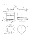
- Einhandhebelmischerkartusche consists essentially of a head piece 1, in which a spindle 2 protrudes axially, which is pivotally mounted in a rotatably mounted spindle receptacle 3 and which engages in a slider 4 which is connected to a control disk 5, with a Passage disk 6 corresponds, which is followed by a bottom piece 8, which on the transmission disk side a seal molding 7 and the inlet side receives a seal molding 80.
- the head piece 1 is sleeve-shaped and manufactured in the embodiment as a brass turned part. At its the bottom piece 8 facing end portion 10 are diametrically opposed to each other two recesses 101 introduced into the head piece 1, are formed by the two arcuate webs 11, on the inside of a locking groove 111 is introduced. At its end opposite the webs 11, the head piece 1 has a reduced-diameter portion 15, through which a circumferential shoulder 150 is formed and in which diametrically opposite two radial oblong holes 152 are inserted, which serve to limit the rotation of the spindle receptacle 3.
- a detent 151 in the form of an undercut forming radial locking edge is arranged in each case.
- the locking lug 151 serves to captively hold the mounting ring 16.
- a shoulder 14 is formed on the head piece 1 inside.
- the head piece 1 At its opposite end of the diameter-reduced portion 15, the head piece 1 has on the outside a circumferential, diameter-enlarged shoulder 13 into which a groove 131 for receiving an O-ring 17 is centrally inserted in the circumferential direction.
- a fastening ring 16 is further turned up.
- the mounting ring 16 is sleeve-shaped and has circumferentially outside an external thread 161 for screwing into a fitting.
- an external hexagon 166 is integrally formed on the fastening ring 16.
- a second external thread 163 is introduced into the fastening ring 16.
- a shoulder 165 is formed inside, on the inside circumferentially a nose 167 is formed.
- the spindle 2 is formed in the embodiment substantially cuboid. Approximately in the middle of the spindle 2, an annular coaxial Anformung 21 for receiving a - not shown - keypad formed. Above the Anformung 21 a guided to the Anformung 21 slot 25 is introduced into the spindle 2. Below the Anformung 21 is introduced through the spindle 2, a bore 22 for receiving an axle pin 23. At the end, a control head 24 designed in the form of a spherical disk is integrally formed on the spindle 2 and is flattened on its side facing the slider 4.
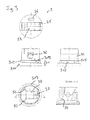
- the spindle receptacle 3 is formed as a substantially cylindrical plastic injection molded part.
- a two-step shoulder 31 is integrally formed on the spindle receptacle 3, the contour of which corresponds to the inner contour of the two-step shoulder 14 of the head piece 1 against which it bears.
- the second shoulder 312 of the two-step shoulder 31, which is arranged above the end-side first shoulder 311 and has a diameter-reduced design, is designed to taper axially inward in the region of the two longitudinal side walls of the rectangular cross section of the bushing 33, so that two cone-section-like bevels 313 are formed below the through-bore 32 ,
- the second shoulder 312 thus has a hammerhead-shaped contour in plan view.
- the sliding ring 38 has a polygonal outer contour, which is formed twelve-sided in the embodiment.
- the outer diameter of this polygonal outer contour is slightly larger than the outer diameter of the first paragraph 311, whose outer diameter is in turn dimensioned slightly smaller than the inner diameter of the shoulder 14 of the head piece. 1
- a radial through hole 32 for receiving the axle pin 23 for the spindle 2 is introduced through the spindle receptacle 3.
- the through hole 32 has a polygonal cross section, which is formed in the embodiment as a toe.
- a bushing 33 for the spindle 2 which has lateral stops 34, by which the pivot radius of the spindle 2 is limited to the axle pin 23.
- the passage 33 has a substantially rectangular cross-section.
- a gap 37 forming a gap is arranged in the spindle receptacle, which slot extends outwardly at an obtuse angle to the transverse side and ends above a horizontal plane imagined by the central axis of the through-bore 32.
- a third slot 37 extends on the longitudinal central axis of the rectangular cross-section of the passage 33 from the aforementioned two slots 37 opposite arranged transverse side to the outside.
- the passage 33 terminates in a substantially parallelepiped-shaped receptacle 35 for the slider 4. Spaced to the receptacle 35 is in the spindle receptacle 3, a substantially oval indentation 36 for receiving the guide pin 44 of the slider 4 is introduced.
- the running as a plastic injection molded part slider 4 is formed substantially in the form of a circular disc on which a substantially cuboidal shaped piece 41 is formed.
- the molding 41 is formed such that it is guided in the longitudinal direction of the receptacle 35 of the spindle receptacle 3 and in the transverse direction. Axial is through the slider 4, the fitting 41 penetrating a slot 42 for receiving the control head 24 of the spindle 2 introduced.
- a guide pin 44 is formed for engagement in the recess 36 of the spindle receptacle 3.
- two axial webs 43 for receiving the control disk 5 are integrally formed on the slider 4 on the outside.
- a dowel pin 45 is integrally formed on the underside for engagement in the fitting bore 53 of the control disk 5, whereby a positionally correct orientation of the control disk 5 is ensured during assembly.
- the control disk 5 is oval and made as a ceramic part. On its side facing the transmission disk 6, the control disk has a centrally arranged, egg-shaped indentation 51. On its upper side opposite the indentation 51, two recesses 52 for receiving the webs 23 of the slider 4 are inserted into the control disk 5 diametrically opposite each other on the outside. Furthermore, in the control disk 5 at its the slider 4 side facing a fitting bore 53 is introduced. About the recesses 52 and the pilot hole 53, the control disk 5 is positively connected to the slider 4.
- the transmission disk 6 is also designed as a ceramic part. Through the passage disc 6 are two inlet channels 61 for cold and hot water and a relative to these enlarged formed outlet channel 62 for the Mixed water introduced. The inlet channels 61 and the outlet channel 62 are guided at an angle to the aperture disk 6 through them. The side offset from each other on the transmission disc 6 three recesses 63 for positive connection with the bottom piece 8 are introduced.
- the seal molding 7 is made in the embodiment of rubber. It is essentially formed by three rings 71, which are each formed on the two remaining rings 71, so that a cloverleaf-like contour is formed. On the rings 71 of the sealing molding 7 each sealing lips 72 are integrally formed on the upper side and on the underside thereof. To stabilize the shape of the rings 71 are each provided with a support ring 73 which is disposed between the sealing lips 72 of the rings 71.
- the bottom piece 8 is substantially cylindrical.
- two inlet bores 81 and an outlet bore 82 are introduced, whose central axes define an isosceles triangle.
- the two inlet bores 81 open into a spectacle-like shaped shoulder 83, into which the inlet bores 81 are surrounded by a groove 84 for receiving a spectacle-shaped sealing molding 80.
- Boden note two support feet 85 are further formed on the bottom piece 8.
- a groove 87 for receiving an O-ring 871 for sealing the bottom piece 8 relative to the head piece 1 is circumferentially introduced on the bottom piece 8.
- a partially circumferential shoulder 86 is formed for conditioning of the head piece 1.
- the bottom piece 8 On its upper side opposite the shoulder 83, the bottom piece 8 has a cloverleaf-like receptacle 88 for the sealing molding 7.
- Surrounding the receptacle 88 are equally spaced from each other three webs 89 for rotationally fixed receiving the aperture disk 6 integrally formed.
- the webs 89 engage in the recesses 63 of the transmission disk 6.
- lugs 891 are formed on two webs 89, which engage in recesses 63 of the transmission disk 6 corresponding thereto.
- Ortogonal to the central axis of the water supply lines empties a water drain line 94 into the cartridge 91.
- positioning holes 95 for receiving the positioning pins 852 of the bottom piece 8 are introduced.
- the fastening ring 16 is slipped over the reduced-diameter portion 15 of the head piece 1, wherein the locking nose 151 is forced inwardly when passing the circumferential nose 167 of the mounting ring 16.
- the detent 151 of the reduced diameter portion 15 of the head piece 1 assumes its original position again.
- the mounting ring 16 is thus held captive on the head piece 1.
- the head piece 1 is at the end on the partially circumferential shoulder 86 of the bottom piece 8, whereby the biasing forces are transmitted almost completely over the head piece 1 on the bottom piece.
- the provided with the spectacle-shaped seal molding 80 paragraph 83 is thus pressed sealingly against the water inlet ports 93.
Abstract
Die Erfindung betrifft eine Einhandhebelkartusche, umfassend ein hülsenartig ausgebildetes Kopfstück (1), das ein Bodenstück (8) aufnimmt, sowie eine Scheibensteuerung mit einer Steuerscheibe (5), welche über eine in einer Spin-delaufnahme (3) drehbar und/ oder schwenkbar gelagerte Spindel (2) relativ zu einer drehfest angeordneten Durchlassscheibe (6) drehbar und/oder verschiebbar angeordnet ist, wobei an dem Kopfstück ein durchmesservergrößerter Absatz (13) angeformt ist, in den umlaufend eine Nut zur Aufnahme eines Dichtelements eingebracht ist, wobei ein mit einem Außengewinde (161) versehener Befestigungsring (16) auf das Kopfstück (1) aufgestülpt ist, wobei der durchmesservergrößerte Absatz (13) an dem der Spindel (2) abgewandten Ende an das Kopfstück (1) angeformt ist.The invention relates to a Einhandhebelkartusche, comprising a sleeve-like head piece (1) which receives a bottom piece (8), and a disc control with a control disc (5), which rotatably and / or pivotally mounted on a in a spin delaufnahme (3) Spindle (2) is arranged rotatable and / or displaceable relative to a non-rotatably mounted passage disc (6), wherein on the head piece a diameter-enlarged shoulder (13) is integrally formed in the circumferential groove for receiving a sealing element is introduced, one with a Male thread (161) provided mounting ring (16) is slipped on the head piece (1), wherein the enlarged diameter shoulder (13) on the spindle (2) facing away from the end of the head piece (1) is integrally formed.
Description
Die Erfindung betrifft eine Einhandhebelkartusche nach dem Oberbegriff des Patentanspruchs 1. Die Erfindung betrifft weiterhin eine Seiteneinhandhebelarmatur nach dem Patentanspruch 13.The invention relates to a Einhandhebelkartusche according to the preamble of
In Sanitärarmaturen werden häufig als Mischerkartuschen ausgeführte Einhandhebelkartuschen eingesetzt, in denen eine Steuerscheibe sowie eine Durchlassscheibe aufweisende Scheibensteuerung angeordnet ist, welche über einen einzigen Hebel derart bedienbar ist, dass sowohl die Wassermenge als auch die Wassertemperatur über ein und denselben Hebel steuerbar ist. Steuerscheibe und Durchlassscheibe sind dabei regelmäßig aus Keramik hergestellt. In einigen Anwendungsgebieten kommen auch modifizierte Kartuschen zum Einsatz, bei denen ein konstantes Mischungsverhältnis eingestellt ist, wobei die Drehbewegung des Hebels blockiert ist. Diese Ausführung kommt auch in solchen Anwendungsgebieten zum Einsatz, in denen nur ein Zulaufkanal in der Armatur vorhanden ist.In sanitary fittings executed as mixer cartridges Einhandhebelkartuschen are often used, in which a control disc and a transmission disc having disc control is arranged, which is operated via a single lever so that both the amount of water and the water temperature is controlled via one and the same lever. Control disc and passage disc are regularly made of ceramic. In some applications also modified cartridges are used, in which a constant mixing ratio is set, the rotation of the lever is blocked. This version is also used in such application areas in which only one inlet channel is present in the valve.
Mischerkartuschen der vorgenannten Art, wie sie beispielsweise in der
Hier will die Erfindung Abhilfe schaffen. Der Erfindung liegt die Aufgabe zugrunde, eine Einhandhebelkartusche für den Einsatz in Seitenarmaturen bereitzustellen, bei der der erforderliche Einbauraum vermindert ist. Gemäß der Erfindung wird diese Aufgabe durch eine Einhandhebelkartusche mit den Merkmalen des kennzeichnenden Teils des Patentanspruchs 1 gelöst.The invention aims to remedy this situation. The invention has for its object to provide a Einhandhebelkartusche for use in side fittings, in which the required installation space is reduced. According to the invention This object is achieved by a single-lever cartridge with the features of the characterizing part of
Mit der Erfindung ist eine Einhandhebelkartusche für den Einsatz in Seitenarmaturen geschaffen, bei der der erforderliche Einbauraum vermindert ist. Dadurch, dass der das Dichtelement aufnehmende durchmesservergrößerte Absatz an dem der Spindel abgewandten Seite an das Kopfstück angeformt ist, ist eine Montage in einer Seitenarmatur ermöglicht, bei der die Kartusche nur in geringem Maße in die Armatur eintaucht, wodurch der erforderliche Einbauraum vermindert ist. Dabei ist das Dichtelement bevorzugt durch einen O-Ring gebildet. Der Befestigungsring liegt hier nicht, wie im Stand der Technik bekannt, auf dem durchmesservergrößerten Absatz auf, sondern auf einer im oberen Bereich des Kopfstücks angeordneten Schulter.With the invention, a Einhandhebelkartusche is created for use in side fittings, in which the required installation space is reduced. Characterized in that the diameter-enlarged shoulder receiving the sealing element is formed on the side facing away from the spindle on the head piece, mounting in a side fitting is made possible, in which the cartridge dives only slightly into the fitting, whereby the required installation space is reduced. In this case, the sealing element is preferably formed by an O-ring. The fastening ring is not located here, as known in the art, on the diameter-enlarged shoulder, but on a arranged in the upper region of the head shoulder.
In Weiterbildung der Erfindung ist der Befestigungsring hülsenförmig ausgebildet und weist eine Höhe auf, die im Wesentlichen der Höhe des Kopfstücks oberhalb des Absatzes entspricht. Hierdurch ist eine vollständige Ummantelung des Kopfstücks oberhalb des zur Abdichtung innerhalb des Ventilsitzes der Armatur zu positionierenden durchmesservergrößerten Absatzes erzielt, wodurch quasi eine Gehäuseerweiterung der Armatur erreicht ist. Dabei ist das Außengewinde bevorzugt an seinem dem durchmesservergrößerten Absatz zugewandten Ende des Befestigungsrings angeordnetIn a further development of the invention, the fastening ring is sleeve-shaped and has a height which corresponds substantially to the height of the head piece above the heel. As a result, a complete sheathing of the head piece is achieved above the diameter to be positioned for sealing within the valve seat of the valve diameter enlarged paragraph, which is virtually achieved a housing extension of the valve. In this case, the external thread is preferably arranged at its end of the fastening ring facing the diameter-enlarged shoulder
In Ausgestaltung der Erfindung sind in dem Bodenstück zumindest ein Einlasskanal, bevorzugt zwei Einlasskanäle sowie ein Auslasskanal eingebracht, wobei das Bodenstück einen axialen Absatz aufweist, durch den nur der wenigstens eine Einlasskanal, nicht jedoch der Auslasskanal geführt ist. Hierdurch ist ein Hohlraum zwischen der Kartusche und der Armatur im Bereich des Auslasskanals bewirkt, durch den ein seitlicher Auslauf aus der Armatur ermöglicht ist.In an embodiment of the invention, at least one inlet channel, preferably two inlet channels and one outlet channel are introduced into the bottom piece, the bottom piece having an axial shoulder, through which only the at least one inlet channel, but not the outlet channel, is guided. As a result, a cavity between the cartridge and the valve is effected in the region of the outlet channel, through which a lateral outlet from the fitting is made possible.
In Weiterbildung der Erfindung ist an dem Bodenstück zumindest bereichsweise umlaufend ein Absatz angeformt, auf dem das Kopfstück aufliegt. Hierdurch ist gewährleistet, dass die bei der Montage der Kartusche in dem Ventilsitz einer Armatur auftretenden Vorspannkräfte im Wesentlichen von dem Kopfstück auf das Bodenstück übertragen werden, wodurch die Vorspannkraft insbesondere nicht durch die Bauteile der Scheibensteuerung geleitet wird.In a further development of the invention, a shoulder is at least partially circumferentially formed on the bottom piece, on which rests the head piece. This ensures that in the assembly of the cartridge in the valve seat of a Armature occurring biasing forces are transmitted substantially from the head piece to the bottom piece, whereby the biasing force is not passed in particular by the components of the disc control.
In weiterer Ausgestaltung der Erfindung sind Kopfstück und Befestigungsring aus Metall, vorzugsweise Messing hergestellt. Hierdurch ist eine Verformung von Kopfstück und Hülse durch die Vorspannung der Kartusche gegen die Armatur auch über einen langen Zeitraum verhindert.In a further embodiment of the invention, the head piece and the fastening ring are made of metal, preferably brass. As a result, a deformation of the head piece and sleeve is prevented by the bias of the cartridge against the valve over a long period.
In Weiterbildung der Erfindung ist die Spindel über eine Achse mit der Spindelaufnahme verbunden und das Kopfstück weist an seinem dem Bodenstück entgegengesetzten Ende einen durchmesserreduzierten Abschnitt auf, in dem diametral gegenüberliegend zwei radiale Langlöcher eingebracht sind, in welche die Achse eingreift. Der durchmesserreduzierte Abschnitt nimmt den Befestigungsring auf, der so von der Spindelaufnahme entkoppelt ist, wodurch eine ungewollte Mitnahme des Befestigungsrings beim Drehen der Spindelaufnahme bei Betätigung der Einhandhebelkartusche vermieden ist.In a further development of the invention, the spindle is connected via an axis with the spindle receptacle and the head has at its bottom end opposite the bottom end a reduced diameter portion in which diametrically opposite two radial slots are inserted, in which engages the axis. The reduced diameter portion receives the mounting ring, which is thus decoupled from the spindle receptacle, whereby an unwanted entrainment of the mounting ring when rotating the spindle receptacle is avoided when operating the Einhandhebelkartusche.
Vorteilhaft sind zwischen den Langlöchern zwei radial umlaufende Stege angeordnet, die bevorzugt einen gegenüber dem durchmesserreduzierten Abschnitt vergrößert ausgebildeten Durchmesser aufweisen. Vorteilhaft ist auf den Stegen jeweils wenigstens eine Rastnase zur verliersicheren Aufnahme eines Befestigungsrings angeordnet. Hierdurch ist eine gute Beweglichkeit des Befestigungsrings bei gleichzeitiger verliersicherer Halterung erzielt. Bevorzugt ist die Rastnase durch eine radial verlaufende, einen Hinterschnitt ausbildende Rastkante gebildet.Advantageously, two radially encircling webs are arranged between the oblong holes, which preferably have an enlarged diameter compared to the diameter-reduced section. Advantageously, at least one locking lug for captively receiving a fastening ring is arranged on the webs in each case. As a result, a good mobility of the mounting ring is achieved while captive holder. Preferably, the locking lug is formed by a radially extending, an undercut forming locking edge.
Der vorliegenden Erfindung liegt weiterhin die Aufgabe zugrunde, eine Seiteneinhandhebelarmatur mit einer Einhandhebelkartusche bereitzustellen, die weniger voluminös ausgeführt sind. Gemäß der Erfindung wird diese Aufgabe durch eine Seiteneinhandhebelarmatur mit den Merkmalen des Patentanspruchs 13 gelöst.The present invention is further based on the object to provide a side Einhandhebelarmatur with a Einhandhebelkartusche that are designed less voluminous. According to the invention, this object is achieved by a Seiteneinhandhebelarmatur with the features of
Andere Weiterbildungen und Ausgestaltungen der Erfindung sind in den übrigen Unteransprüchen angegeben. Ein Ausführungsbeispiel der Erfindung ist in den Zeichnungen dargestellt und wird nachfolgend im Einzelnen beschrieben. Es zeigen:
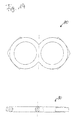
Figur 1- die schematische Darstellung einer Einhandhebelmischerkartusche
- a) in der Ansicht von unten;
- b) in der Seitenansicht;
- c) in der Draufsicht;
- d) im Teillängsschnitt (mit angedeuteter Armatur);
Figur 2- die schematische Darstellung des Kopfstücks der Mischerkartusche aus
Figur 1- a) im Längsschnitt;
- b) in einer um 90° gedrehter Seitenansicht;
- c) im Querschnitt (Schnitt A-A);
- d) im Querschnitt (Schnitt B-B);
Figur 3- die schematische Darstellung der Spindelaufnahme der Mischerkartusche aus
Figur 1- a) in der Ansicht von unten;
- b) in der Seitenansicht;
- c) in einer um 90° verdrehten Seitenansicht;
- d) in der Draufsicht;
- e) im Längsschnitt (Schnitt A-A);
Figur 4- die Spindel der Mischerkartusche aus
Figur 1- a) in der Seitenansicht;
- b) im Teilschnitt in um 90° gedrehter Seitenansicht;
- c) in der Draufsicht;
- d) im Längsschnitt (Schnitt B-B);
- e) im Querschnitt (Schnitt A-A);
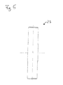
Figur 5- die Schwenkachse der Spindel der Mischerkartusche aus
Figur 1; Figur 6- den Befestigungsring der Mischerkartusche aus
Figur 1- a) im Längsschnitt;
- b) in der Draufsicht;
Figur 7- die schematische Darstellung des Gleitstücks der Mischerkartusche aus
Figur 1 - a) in der Ansicht von unten ;
- b) im Querschnitt ;
- c) in der Draufsicht;
- d) in der Seitenansicht;
Figur 8- die Darstellung der Steuerscheibe der Mischerkartusche aus
Figur 1 - a) in der Ansicht von unten;
- b) im Querschnitt (Schnitt A-A);
- c) in der Draufsicht;
- d) im Querschnitt (Schnitt B-B);
Figur 9- die Darstellung der Durchlassscheibe der Mischerkartusche aus
Figur 1 - a) in der Ansicht von unten;
- b) im Querschnitt;
- c) in der Draufsicht;
Figur 10- die Darstellung des Bodenstücks des Mischerkartusche aus
Figur 1 - a) in der Draufsicht;
- b) im Längsschnitt;
- c) in der Ansicht von unten;
- d) im Schnitt D-D der Darstellung aus b);
- e) in der Seitenansicht;
- f) in der Seitenansicht (um 90° verdreht);
- g) im Schnitt B-B der Darstellung aus b)
- h) im Schnitt C-C der Darstellung aus b)
- i) im Schnitt A-A der Darstellung aus b)
- Figur 11
- die Darstellung des durchlassscheibenseitigen Lippendichtungsformteils der Mischerkartusche aus
Figur 1 - a) in der Draufsicht;
- b) im Längsschnitt (Schnitt A-A);
- c) im Längsschnitt (Schnitt B-B);
- d) im Längsschnitt (Schnitt C-C);
- Figur 12
- die Darstellung des Stützrings des Lippendichtungsformteils der Mischerkartusche aus
Figur 1 - a) im Längsschnitt;
- b) in der Draufsicht;
Figur 13- die Darstellung des Gleitrings der Mischerkartusche aus Figur 1
- a) im Längsschnitt;
- b) in der Draufsicht;
Figur 14- die Darstellung des einlassseitigen Lippendichtungsformteils der Mischerkartusche aus
Figur 1 - a) in der Draufsicht;
- b) im Querschnitt.
- FIG. 1
- the schematic representation of a Einhandhebelmischerkartusche
- a) in the view from below;
- b) in side view;
- c) in plan view;
- d) in partial longitudinal section (with indicated fitting);
- FIG. 2
- the schematic representation of the head of the mixer cartridge
FIG. 1 - a) in longitudinal section;
- b) in a side view rotated by 90 °;
- c) in cross section (section AA);
- d) in cross-section (section BB);
- FIG. 3
- the schematic representation of the spindle receptacle of the mixer cartridge
FIG. 1 - a) in the view from below;
- b) in side view;
- c) in a rotated by 90 ° side view;
- d) in plan view;
- e) in longitudinal section (section AA);
- FIG. 4
- the spindle of the mixer cartridge off
FIG. 1 - a) in side view;
- b) in partial section in 90 ° rotated side view;
- c) in plan view;
- d) in longitudinal section (section BB);
- e) in cross-section (section AA);
- FIG. 5
- the pivot axis of the spindle of the mixer cartridge of Figure 1;
- FIG. 6
- from the mounting ring of the mixer cartridge
FIG. 1 - a) in longitudinal section;
- b) in plan view;
- FIG. 7
- the schematic representation of the slider of the mixer cartridge
FIG. 1 - a) in the view from below;
- b) in cross section;
- c) in plan view;
- d) in side view;
- FIG. 8
- the representation of the control disc of the mixer cartridge
FIG. 1 - a) in the view from below;
- b) in cross-section (section AA);
- c) in plan view;
- d) in cross-section (section BB);
- FIG. 9
- the representation of the passage disc of the mixer cartridge
FIG. 1 - a) in the view from below;
- b) in cross section;
- c) in plan view;
- FIG. 10
- the representation of the bottom piece of the mixer cartridge
FIG. 1 - a) in plan view;
- b) in longitudinal section;
- c) in the view from below;
- d) in section DD of the representation from b);
- e) in side view;
- f) in the side view (rotated by 90 °);
- g) in section BB of the representation from b)
- h) in section CC of the representation from b)
- i) in section AA of the representation from b)
- FIG. 11
- the representation of the Durchlaßscheibenseitigen lip seal molding of the mixer cartridge
FIG. 1 - a) in plan view;
- b) in longitudinal section (section AA);
- c) in longitudinal section (section BB);
- d) in longitudinal section (section CC);
- FIG. 12
- the representation of the support ring of the lip seal molding of the mixer cartridge
FIG. 1 - a) in longitudinal section;
- b) in plan view;
- FIG. 13
- the representation of the sliding ring of the mixer cartridge of Figure 1
- a) in longitudinal section;
- b) in plan view;
- FIG. 14
- the representation of the inlet-side lip seal molding of the mixer cartridge
FIG. 1 - a) in plan view;
- b) in cross-section.
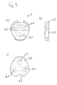
Die als Ausführungsbeispiel gewählte Einhandhebelmischerkartusche besteht im Wesentlichen aus einem Kopfstück 1, in das eine Spindel 2 axial hineinragt, die in einer drehbar gelagerten Spindelaufnahme 3 schwenkbar gelagert ist und die in ein Gleitstück 4 eingreift, das mit einer Steuerscheibe 5 verbunden ist, die mit einer Durchlassscheibe 6 korrespondiert, an die sich ein Bodenstück 8 anschließt, welches durchlassscheibenseitige ein Dichtungsformteil 7 und einlassseitig ein Dichtungsformteil 80 aufnimmt.The selected as an embodiment Einhandhebelmischerkartusche consists essentially of a
Das Kopfstück 1 ist hülsenartig ausgebildet und im Ausführungsbeispiel als Messingdrehteil hergestellt. An seinen dem Bodenstück 8 zugewandten endseitigen Abschnitt 10 sind in das Kopfstück 1 diametral zueinander zwei Ausnehmungen 101 eingebracht, durch die zwei bogenförmige Stege 11 gebildet sind, an deren Innenseite eine Rastnut 111 eingebracht ist. An seinem den Stegen 11 gegenüberliegenden Ende weist das Kopfstück 1 einen durchmesserreduzierten Abschnitt 15 auf, durch den eine umlaufende Schulter 150 ausgebildet ist und in dem diametral gegenüberliegend zwei radiale Langlöcher 152 eingebracht sind, welche der Drehbegrenzung der Spindelaufnahme 3 dienen. Zwischen den Langlöchern 152 sind zwei radial umlaufende Stege 153 ausgebildet, die einen gegenüber dem durchmesserreduzierten Abschnitt 15 vergrößerten Außendurchmesser aufweisen. Auf den Stegen 153 ist jeweils eine Rastnase 151 in Form einer einen Hinterschnitt ausbildenden radialen Rastkante angeordnet. Die Rastnase 151 dient der verliersicheren Halterung des Befestigungsrings 16. Unterhalb des durchmesserreduzierten Abschnitts 15 ist an dem Kopfstück 1 innen ein Absatz 14 ausgebildet.The
An seinem dem durchmesserreduzierten Abschnitt 15 gegenüberliegenden Ende weist das Kopfstück 1 außen einen umlaufenden, durchmesservergrößerten Absatz 13 auf, in den mittig umlaufend eine Nut 131 zur Aufnahme eines O-Rings 17 eingebracht ist.At its opposite end of the diameter-reduced portion 15, the
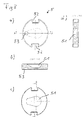
Auf den durchmesserreduzierten Abschnitt 15 des Kopfstücks 1 ist weiterhin ein Befestigungsring 16 aufgestülpt. Der Befestigungsring 16 ist hülsenförmig ausgebildet und weist außen umlaufend ein Außengewinde 161 zum Einschrauben in eine Armatur auf. An seiner dem Außengewinde 161 entgegengesetzten Seite ist an dem Befestigungsring 16 ein Außensechskant 166 angeformt. Unterhalb des Außensechskants 166 ist in dem Befestigungsring 16 ein zweites Außengewinde 163 eingebracht. Beabstandet zu dem zweiten Außengewinde 163 ist innen ein Absatz 165 gebildet, an den innen umlaufend eine Nase 167 angeformt ist.On the reduced diameter portion 15 of the
Die Spindel 2 ist im Ausführungsbeispiel im Wesentlichen quaderförmig ausgebildet. Etwa mittig ist an der Spindel 2 eine kreisringförmige koaxiale Anformung 21 zur Aufnahme eines - nicht dargestellten - Bedienteils angeformt. Oberhalb der Anformung 21 ist in die Spindel 2 ein bis zu der Anformung 21 geführter Schlitz 25 eingebracht. Unterhalb der Anformung 21 ist durch die Spindel 2 eine Bohrung 22 zur Aufnahme eines Achsstiftes 23 eingebracht. Endseitig ist an die Spindel 2 ein in Form einer Kugelscheibe ausgebildeter Steuerkopf 24 angeformt, der an seiner dem Gleitstück 4 zugewandten Seite abgeflacht ausgebildet ist.The
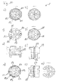
Die Spindelaufnahme 3 ist als im Wesentlichen zylinderförmiges Kunststoffspritzgussteil ausgebildet. An seinem dem Gleitstück 4 zugewandten Ende ist an der Spindelaufnahme 3 ein zweistufiger Absatz 31 angeformt, dessen Kontur der Innenkontur des zweistufigen Absatzes 14 des Kopfstücks 1 entspricht, an der dieser anliegt. Der oberhalb des endseitigen ersten Absatzes 311 angeordnete, gegenüber diesem durchmesserreduziert ausgebildete zweite Absatz 312 des zweistufigen Absatzes 31 ist im Bereich der beiden Längsseitenwände des rechteckigen Querschnitts der Durchführung 33 axial schräg nach innen zulaufend ausgebildet, sodass unterhalb der Durchgangsbohrung 32 zwei konusabschnittartige Schrägen 313 gebildet sind. Der zweite Absatz 312 weist hierdurch in der Draufsicht eine hammerkopfförmige Kontur auf. Auf dem ersten Absatz 311 ist ein Gleitring 38 angeordnet. Der Gleitring 38 weist eine polygonale Außenkontur auf, die im Ausführungsbeispiel zwölfeckig ausgebildet ist. Der Außendurchmesser dieser polygonalen Außenkontur ist dabei geringfügig größer als der Außendurchmesser des ersten Absatzes 311, dessen Außendurchmesser wiederum geringfügig kleiner dimensioniert ist, als der Innendurchmesser des Absatzes 14 des Kopfstücks 1.The
Oberhalb des zweitstufigen Absatzes 31 ist durch die Spindelaufnahme 3 eine radiale Durchgangsbohrung 32 zur Aufnahme des Achsstiftes 23 für die Spindel 2 eingebracht. Die Durchgangsbohrung 32 weist einen polygonalen Querschnitt auf, der im Ausführungsbeispiel als Zehneck ausgebildet ist. Axial ist durch die Spindelaufnahme 3 eine Durchführung 33 für die Spindel 2 angeformt, welche seitliche Anschläge 34 aufweist, durch die der Schwenkradius der Spindel 2 um den Achsstift 23 begrenzt ist. Die Durchführung 33 weist einen im Wesentlichen rechteckigen Querschnitt auf. An zwei eine Querseite des rechteckigen Querschnitts begrenzenden Ecken ist in die Spindelaufnahme jeweils ein einen Spalt ausbildender Schlitz 37 angeordnet, der sich in einem stumpfen Winkel zur Querseite nach außen erstreckt und der oberhalb einer durch die Mittelachse der Durchgangsbohrung 32 gedachten horizontalen Ebene endet. Ein dritter Schlitz 37 verläuft auf der Längsmittelachse des rechteckförmigen Querschnitts der Durchführung 33 von der den vorgenannten beiden Schlitzen 37 gegenüberliegend angeordneten Querseite nach außen.Above the second-
Die Durchführung 33 mündet in einer im Wesentlichen quaderförmig ausgebildeten Aufnahme 35 für das Gleitstück 4. Beabstandet zu der Aufnahme 35 ist in der Spindelaufnahme 3 eine im Wesentlichen ovale Einbuchtung 36 zur Aufnahme des Führungsstiftes 44 des Gleitstücks 4 eingebracht.The
Das als Kunststoffspritzgussteil ausgeführte Gleitstück 4 ist im Wesentlichen in Form einer Kreisscheibe ausgebildet, auf der ein im Wesentlichen quaderförmiges Formstück 41 angeformt ist. Das Formstück 41 ist derart ausgebildet, dass es innerhalb der Aufnahme 35 der Spindelaufnahme 3 in Längsrichtung verschiebbar und in Querrichtung geführt ist. Axial ist durch das Gleitstück 4 das Formstück 41 durchdringend ein Langloch 42 zur Aufnahme des Steuerkopfes 24 der Spindel 2 eingebracht. Seitlich des Formstücks 41 ist ein Führungsstift 44 zum Eingriff in die Einbuchtung 36 der Spindelaufnahme 3 angeformt. An seiner dem Formstück 41 entgegen gerichteten Unterseite sind an dem Gleitstück 4 außen gegenüberliegend zwei axiale Stege 43 zur Aufnahme der Steuerscheibe 5 angeformt. Weiterhin ist an der Unterseite ein Passstift 45 zum Eingriff in die Passbohrung 53 der Steuerscheibe 5 angeformt, wodurch eine lagegerechte Orientierung der Steuerscheibe 5 bei der Montage gewährleistet ist.The running as a plastic injection molded
Die Steuerscheibe 5 ist oval ausgebildet und als Keramikteil hergestellt. Auf ihrer der Durchlassscheibe 6 zugewandten Seite weist die Steuerscheibe eine mittig angeordnete, eiförmige Einbuchtung 51 auf. Auf ihrer der Einbuchtung 51 entgegen gesetzten Oberseite sind in der Steuerscheibe 5 diametral zueinander außen zwei Ausnehmungen 52 zur Aufnahme der Stege 23 des Gleitstücks 4 eingebracht. Weiterhin ist in der Steuerscheibe 5 an ihrer dem Gleitstück 4 zugewandten Seite eine Passbohrung 53 eingebracht. Über die Ausnehmungen 52 sowie die Passbohrung 53 ist die Steuerscheibe 5 mit dem Gleitstück 4 formschlüssig verbunden.The
Die Durchlassscheibe 6 ist ebenfalls als Keramikteil ausgeführt. Durch die Durchlassscheibe 6 sind zwei Einlasskanäle 61 für kaltes bzw. warmes Wasser sowie ein relativ zu diesen vergrößert ausgebildeter Auslasskanal 62 für das Mischwasser eingebracht. Die Einlasskanäle 61 sowie der Auslasskanal 62 sind schräg zur Durchlassscheibe 6 durch diese hindurch geführt. Seitlich sind an der Durchlassscheibe 6 versetzt zueinander drei Aussparungen 63 zur formschlüssigen Verbindung mit dem Bodenstück 8 eingebracht.The
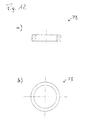
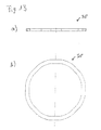
Das Dichtungsformteil 7 ist im Ausführungsbeispiel aus Gummi hergestellt. Es ist im Wesentlichen durch drei Ringe 71 gebildet, die jeweils an den beiden übrigen Ringen 71 angeformt sind, sodass eine kleeblattartige Kontur gebildet ist. An den Ringen 71 des Dichtungsformteils 7 sind an deren Oberseite sowie an deren Unterseite jeweils Dichtlippen 72 angeformt. Zur Formstabilisierung sind die Ringe 71 jeweils mit einem Stützring 73 versehen, welche zwischen den Dichtlippen 72 der Ringe 71 angeordnet ist.The
Das Bodenstück 8 ist im Wesentlichen zylinderförmig ausgebildet. In dem Bodenstück 8 sind zwei Einlassbohrungen 81 sowie eine Auslassbohrung 82 eingebracht, deren Mittelachsen ein gleichschenkliges Dreieck begrenzen. Die beiden Einlassbohrungen 81 münden in einen brillenartig ausgeformten Absatz 83, in den die Einlassbohrungen 81 umrandend eine Nut 84 zur Aufnahme eines brillenförmigen Dichtungsformteils 80 eingebracht ist. Bodenseitig sind weiterhin zwei Stützfüße 85 an dem Bodenstück 8 angeformt.The
Seitlich ist an dem Bodenstück 8 umlaufend eine Nut 87 zur Aufnahme eines O-Rings 871 zur Abdichtung des Bodenstücks 8 gegenüber dem Kopfstück 1 eingebracht. Unterhalb der Nut 87 ist ein bereichsweise umlaufender Absatz 86 zur Anlage des Kopfstücks 1 angeformt. Auf seiner dem Absatz 83 gegenüberliegenden Oberseite weist das Bodenstück 8 eine kleeblattartige Aufnahme 88 für das Dichtungsformteil 7 auf. Umlaufend der Aufnahme 88 sind gleichmäßig beabstandet zueinander drei Stege 89 zur drehfesten Aufnahme der Durchlassscheibe 6 angeformt. Die Stege 89 greifen in die Aussparungen 63 der Durchlassscheibe 6 ein. Zur Verbesserung des Formschlusses sind an zwei Stegen 89 Nasen 891 angeformt, welche in hierzu korrespondierende Aussparungen 63 der Durchlassscheibe 6 eingreifen.Laterally, a
Die Seiteneinhandhebelarmatur 9, die in
Im montierten Zustand ist der Befestigungsring 16 auf den durchmesserreduzierten Abschnitt 15 des Kopfstücks 1 übergestülpt, wobei die Rastnase 151 bei Passieren der umlaufenden Nase 167 des Befestigungsrings 16 elastisch nach innen gezwängt wird. Nach Passieren der Nase 167 des Befestigungsrings 116 nimmt die Rastnase 151 des durchmesserreduzierten Abschnitts 15 des Kopfstücks 1 ihre ursprüngliche Position wieder ein. Der Befestigungsring 16 ist somit verliersicher an dem Kopfstück 1 gehalten. Das Einschrauben des Befestigungsrings 16 in den Ventilsitz 91 der Armatur 9 erfolgt über den Außensechskant 166 wodurch über die Schulter 150 Vorspannkräfte auf das Kopfstück 1 eingeleitet werden. Dabei liegt das Kopfstück 1 endseitig auf dem bereichsweise umlaufenden Absatz 86 des Bodenstücks 8 auf, wodurch die Vorspannkräfte nahezu vollständig über das Kopfstück 1 auf das Bodenstück übertragen werden. Der mit dem brillenförmigen Dichtungsformteil 80 versehene Absatz 83 wird so abdichtend gegen die Wasserzulaufanschlüsse 93 gedrückt.In the assembled state, the
Claims (13)
dadurch gekennzeichnet, dass in dem Bodenstück (8) wenigstens ein Einlasskanal (81) und ein Auslasskanal (82) eingebracht sind, wobei das Bodenstück (8) einen axialen Absatz (83) aufweist, durch den nur der wenigstens eine Einlasskanal (81) geführt ist.Single lever cartridge according to one of the preceding claims,
characterized in that in the bottom piece (8) at least one inlet channel (81) and an outlet channel (82) are introduced, wherein the bottom piece (8) has an axial shoulder (83) through which only the at least one inlet channel (81) out is.
dadurch gekennzeichnet, dass an dem Bodenstück (8) zumindest bereichsweise umlaufend ein Absatz (86) angeformt ist, auf dem das Kopfstück (1) aufliegt.Single lever cartridge according to one of the preceding claims,
characterized in that on the bottom piece (8) at least partially peripherally a shoulder (86) is formed, on which the head piece (1) rests.
dadurch gekennzeichnet, dass Kopfstück (1) und Befestigungsring (16) aus Metall, vorzugsweise Messing hergestellt sind.Single lever cartridge according to one of the preceding claims,
characterized in that the head piece (1) and fastening ring (16) are made of metal, preferably brass.
dadurch gekennzeichnet, dass die Spindel (2) über eine Achse (23) mit der Spindelaufnahme (3) verbunden ist, wobei das Kopfstück (1) an seinem dem Bodenstück (8) entgegen gesetzten Ende einen durchmesserreduzierten Abschnitt (15) aufweist, in dem diametral gegenüberliegend zwei radiale Langlöcher (152) eingebracht sind, in welche die Achse (23) eingreift.Single lever cartridge according to one of the preceding claims,
characterized in that the spindle (2) via an axis (23) with the spindle receptacle (3) is connected, wherein the head piece (1) at its the bottom piece (8) opposite end has a reduced diameter portion (15) in which diametrically opposite two radial slots (152) are introduced, in which the axis (23) engages.
dass die Rastnase (151) durch eine radial verlaufende, einen Hinterschnitt ausbildende Rastkante gebildet ist.Single lever cartridge according to claim 11, characterized
that the detent (151) is formed by a radially extending, forming an undercut latching edge.
Priority Applications (3)
| Application Number | Priority Date | Filing Date | Title |
|---|---|---|---|
| HUE15156605A HUE033173T2 (en) | 2015-02-25 | 2015-02-25 | Single hand lever cartridge |
| EP15156605.6A EP3062003B1 (en) | 2015-02-25 | 2015-02-25 | Single hand lever cartridge |
| ES15156605.6T ES2638404T3 (en) | 2015-02-25 | 2015-02-25 | Single lever cartridge |
Applications Claiming Priority (1)
| Application Number | Priority Date | Filing Date | Title |
|---|---|---|---|
| EP15156605.6A EP3062003B1 (en) | 2015-02-25 | 2015-02-25 | Single hand lever cartridge |
Publications (2)
| Publication Number | Publication Date |
|---|---|
| EP3062003A1 true EP3062003A1 (en) | 2016-08-31 |
| EP3062003B1 EP3062003B1 (en) | 2017-05-31 |
Family
ID=52574081
Family Applications (1)
| Application Number | Title | Priority Date | Filing Date |
|---|---|---|---|
| EP15156605.6A Active EP3062003B1 (en) | 2015-02-25 | 2015-02-25 | Single hand lever cartridge |
Country Status (3)
| Country | Link |
|---|---|
| EP (1) | EP3062003B1 (en) |
| ES (1) | ES2638404T3 (en) |
| HU (1) | HUE033173T2 (en) |
Citations (6)
| Publication number | Priority date | Publication date | Assignee | Title |
|---|---|---|---|---|
| US4617965A (en) * | 1984-05-23 | 1986-10-21 | Hans Grohe Gmbh & Co. Kg | Control insert for sanitary mixer valves |
| FR2699250A3 (en) * | 1992-12-15 | 1994-06-17 | Roshera Sa | Improvement to water tap control - includes conventional structure with toric joint, at its lower part, situated between cartridge and collector plug, with annular seat situated in collector plug |
| US6131611A (en) * | 1997-12-15 | 2000-10-17 | Knapp; Francesco | Cartridge or mechanism for a sequential mixing valve |
| US20030140413A1 (en) * | 2000-03-09 | 2003-07-31 | Gerhard Ginter | Sanitary appliance |
| EP2634463A1 (en) | 2012-02-28 | 2013-09-04 | Flühs Drehtechnik GmbH | Single hand lever mixer cartridge |
| DE202014101116U1 (en) * | 2014-03-12 | 2014-04-07 | Flühs Drehtechnik GmbH | plumbing fixture |
-
2015
- 2015-02-25 HU HUE15156605A patent/HUE033173T2/en unknown
- 2015-02-25 EP EP15156605.6A patent/EP3062003B1/en active Active
- 2015-02-25 ES ES15156605.6T patent/ES2638404T3/en active Active
Patent Citations (6)
| Publication number | Priority date | Publication date | Assignee | Title |
|---|---|---|---|---|
| US4617965A (en) * | 1984-05-23 | 1986-10-21 | Hans Grohe Gmbh & Co. Kg | Control insert for sanitary mixer valves |
| FR2699250A3 (en) * | 1992-12-15 | 1994-06-17 | Roshera Sa | Improvement to water tap control - includes conventional structure with toric joint, at its lower part, situated between cartridge and collector plug, with annular seat situated in collector plug |
| US6131611A (en) * | 1997-12-15 | 2000-10-17 | Knapp; Francesco | Cartridge or mechanism for a sequential mixing valve |
| US20030140413A1 (en) * | 2000-03-09 | 2003-07-31 | Gerhard Ginter | Sanitary appliance |
| EP2634463A1 (en) | 2012-02-28 | 2013-09-04 | Flühs Drehtechnik GmbH | Single hand lever mixer cartridge |
| DE202014101116U1 (en) * | 2014-03-12 | 2014-04-07 | Flühs Drehtechnik GmbH | plumbing fixture |
Also Published As
| Publication number | Publication date |
|---|---|
| HUE033173T2 (en) | 2017-11-28 |
| EP3062003B1 (en) | 2017-05-31 |
| ES2638404T3 (en) | 2017-10-20 |
Similar Documents
| Publication | Publication Date | Title |
|---|---|---|
| DE3419209A1 (en) | MIXING VALVE | |
| EP2634464B1 (en) | Single hand lever mixer cartridge | |
| EP2634463B1 (en) | Single hand lever mixer cartridge | |
| EP2771600B1 (en) | Single-lever mixing cartridge | |
| EP2962020B1 (en) | Single hand lever cartridge | |
| EP3591267B1 (en) | Upper part of a valve | |
| EP3062003B1 (en) | Single hand lever cartridge | |
| DE102011009774B4 (en) | Umstellventiloberteil | |
| DE202013104200U1 (en) | Single lever cartridge | |
| DE202015100918U1 (en) | Single lever cartridge | |
| EP2962021B1 (en) | One-hand lever cartridge | |
| EP3064812B1 (en) | Single hand lever cartridge | |
| DE202019100770U1 (en) | Valve head for sanitary fittings | |
| EP3265704B1 (en) | Valve bonnet for fittings | |
| WO2020007565A1 (en) | Valve top | |
| EP3693643B1 (en) | Valve top section for sanitary fittings | |
| WO2013010845A1 (en) | Valve bonnet for fittings | |
| DE202012100686U1 (en) | Hand lever mixer cartridge | |
| DE202013100899U1 (en) | Single lever cartridge | |
| DE202012100687U1 (en) | Hand lever mixer cartridge | |
| EP3062001A1 (en) | Upper part of a valve | |
| EP2023027A2 (en) | Hose connector | |
| DE202013101794U1 (en) | angle valve | |
| EP2799749A1 (en) | Valve device | |
| EP2696117A1 (en) | Valve top |
Legal Events
| Date | Code | Title | Description |
|---|---|---|---|
| PUAI | Public reference made under article 153(3) epc to a published international application that has entered the european phase |
Free format text: ORIGINAL CODE: 0009012 |
|
| 17P | Request for examination filed |
Effective date: 20160218 |
|
| AK | Designated contracting states |
Kind code of ref document: A1 Designated state(s): AL AT BE BG CH CY CZ DE DK EE ES FI FR GB GR HR HU IE IS IT LI LT LU LV MC MK MT NL NO PL PT RO RS SE SI SK SM TR |
|
| AX | Request for extension of the european patent |
Extension state: BA ME |
|
| GRAP | Despatch of communication of intention to grant a patent |
Free format text: ORIGINAL CODE: EPIDOSNIGR1 |
|
| INTG | Intention to grant announced |
Effective date: 20170220 |
|
| GRAS | Grant fee paid |
Free format text: ORIGINAL CODE: EPIDOSNIGR3 |
|
| GRAJ | Information related to disapproval of communication of intention to grant by the applicant or resumption of examination proceedings by the epo deleted |
Free format text: ORIGINAL CODE: EPIDOSDIGR1 |
|
| GRAL | Information related to payment of fee for publishing/printing deleted |
Free format text: ORIGINAL CODE: EPIDOSDIGR3 |
|
| GRAJ | Information related to disapproval of communication of intention to grant by the applicant or resumption of examination proceedings by the epo deleted |
Free format text: ORIGINAL CODE: EPIDOSDIGR1 |
|
| GRAR | Information related to intention to grant a patent recorded |
Free format text: ORIGINAL CODE: EPIDOSNIGR71 |
|
| GRAA | (expected) grant |
Free format text: ORIGINAL CODE: 0009210 |
|
| INTC | Intention to grant announced (deleted) | ||
| INTG | Intention to grant announced |
Effective date: 20170418 |
|
| AK | Designated contracting states |
Kind code of ref document: B1 Designated state(s): AL AT BE BG CH CY CZ DE DK EE ES FI FR GB GR HR HU IE IS IT LI LT LU LV MC MK MT NL NO PL PT RO RS SE SI SK SM TR |
|
| REG | Reference to a national code |
Ref country code: CH Ref legal event code: EP Ref country code: GB Ref legal event code: FG4D Free format text: NOT ENGLISH |
|
| REG | Reference to a national code |
Ref country code: AT Ref legal event code: REF Ref document number: 897799 Country of ref document: AT Kind code of ref document: T Effective date: 20170615 |
|
| REG | Reference to a national code |
Ref country code: IE Ref legal event code: FG4D Free format text: LANGUAGE OF EP DOCUMENT: GERMAN |
|
| REG | Reference to a national code |
Ref country code: DE Ref legal event code: R096 Ref document number: 502015001130 Country of ref document: DE |
|
| REG | Reference to a national code |
Ref country code: NL Ref legal event code: MP Effective date: 20170531 |
|
| REG | Reference to a national code |
Ref country code: LT Ref legal event code: MG4D |
|
| REG | Reference to a national code |
Ref country code: ES Ref legal event code: FG2A Ref document number: 2638404 Country of ref document: ES Kind code of ref document: T3 Effective date: 20171020 |
|
| PG25 | Lapsed in a contracting state [announced via postgrant information from national office to epo] |
Ref country code: NO Free format text: LAPSE BECAUSE OF FAILURE TO SUBMIT A TRANSLATION OF THE DESCRIPTION OR TO PAY THE FEE WITHIN THE PRESCRIBED TIME-LIMIT Effective date: 20170831 Ref country code: GR Free format text: LAPSE BECAUSE OF FAILURE TO SUBMIT A TRANSLATION OF THE DESCRIPTION OR TO PAY THE FEE WITHIN THE PRESCRIBED TIME-LIMIT Effective date: 20170901 Ref country code: HR Free format text: LAPSE BECAUSE OF FAILURE TO SUBMIT A TRANSLATION OF THE DESCRIPTION OR TO PAY THE FEE WITHIN THE PRESCRIBED TIME-LIMIT Effective date: 20170531 Ref country code: LT Free format text: LAPSE BECAUSE OF FAILURE TO SUBMIT A TRANSLATION OF THE DESCRIPTION OR TO PAY THE FEE WITHIN THE PRESCRIBED TIME-LIMIT Effective date: 20170531 Ref country code: FI Free format text: LAPSE BECAUSE OF FAILURE TO SUBMIT A TRANSLATION OF THE DESCRIPTION OR TO PAY THE FEE WITHIN THE PRESCRIBED TIME-LIMIT Effective date: 20170531 |
|
| REG | Reference to a national code |
Ref country code: HU Ref legal event code: AG4A Ref document number: E033173 Country of ref document: HU |
|
| PG25 | Lapsed in a contracting state [announced via postgrant information from national office to epo] |
Ref country code: BG Free format text: LAPSE BECAUSE OF FAILURE TO SUBMIT A TRANSLATION OF THE DESCRIPTION OR TO PAY THE FEE WITHIN THE PRESCRIBED TIME-LIMIT Effective date: 20170831 Ref country code: LV Free format text: LAPSE BECAUSE OF FAILURE TO SUBMIT A TRANSLATION OF THE DESCRIPTION OR TO PAY THE FEE WITHIN THE PRESCRIBED TIME-LIMIT Effective date: 20170531 Ref country code: NL Free format text: LAPSE BECAUSE OF FAILURE TO SUBMIT A TRANSLATION OF THE DESCRIPTION OR TO PAY THE FEE WITHIN THE PRESCRIBED TIME-LIMIT Effective date: 20170531 Ref country code: RS Free format text: LAPSE BECAUSE OF FAILURE TO SUBMIT A TRANSLATION OF THE DESCRIPTION OR TO PAY THE FEE WITHIN THE PRESCRIBED TIME-LIMIT Effective date: 20170531 Ref country code: IS Free format text: LAPSE BECAUSE OF FAILURE TO SUBMIT A TRANSLATION OF THE DESCRIPTION OR TO PAY THE FEE WITHIN THE PRESCRIBED TIME-LIMIT Effective date: 20170930 Ref country code: SE Free format text: LAPSE BECAUSE OF FAILURE TO SUBMIT A TRANSLATION OF THE DESCRIPTION OR TO PAY THE FEE WITHIN THE PRESCRIBED TIME-LIMIT Effective date: 20170531 |
|
| PG25 | Lapsed in a contracting state [announced via postgrant information from national office to epo] |
Ref country code: SK Free format text: LAPSE BECAUSE OF FAILURE TO SUBMIT A TRANSLATION OF THE DESCRIPTION OR TO PAY THE FEE WITHIN THE PRESCRIBED TIME-LIMIT Effective date: 20170531 Ref country code: RO Free format text: LAPSE BECAUSE OF FAILURE TO SUBMIT A TRANSLATION OF THE DESCRIPTION OR TO PAY THE FEE WITHIN THE PRESCRIBED TIME-LIMIT Effective date: 20170531 Ref country code: CZ Free format text: LAPSE BECAUSE OF FAILURE TO SUBMIT A TRANSLATION OF THE DESCRIPTION OR TO PAY THE FEE WITHIN THE PRESCRIBED TIME-LIMIT Effective date: 20170531 Ref country code: DK Free format text: LAPSE BECAUSE OF FAILURE TO SUBMIT A TRANSLATION OF THE DESCRIPTION OR TO PAY THE FEE WITHIN THE PRESCRIBED TIME-LIMIT Effective date: 20170531 Ref country code: EE Free format text: LAPSE BECAUSE OF FAILURE TO SUBMIT A TRANSLATION OF THE DESCRIPTION OR TO PAY THE FEE WITHIN THE PRESCRIBED TIME-LIMIT Effective date: 20170531 |
|
| PG25 | Lapsed in a contracting state [announced via postgrant information from national office to epo] |
Ref country code: PL Free format text: LAPSE BECAUSE OF FAILURE TO SUBMIT A TRANSLATION OF THE DESCRIPTION OR TO PAY THE FEE WITHIN THE PRESCRIBED TIME-LIMIT Effective date: 20170531 Ref country code: SM Free format text: LAPSE BECAUSE OF FAILURE TO SUBMIT A TRANSLATION OF THE DESCRIPTION OR TO PAY THE FEE WITHIN THE PRESCRIBED TIME-LIMIT Effective date: 20170531 |
|
| REG | Reference to a national code |
Ref country code: DE Ref legal event code: R097 Ref document number: 502015001130 Country of ref document: DE |
|
| PLBE | No opposition filed within time limit |
Free format text: ORIGINAL CODE: 0009261 |
|
| STAA | Information on the status of an ep patent application or granted ep patent |
Free format text: STATUS: NO OPPOSITION FILED WITHIN TIME LIMIT |
|
| 26N | No opposition filed |
Effective date: 20180301 |
|
| REG | Reference to a national code |
Ref country code: CH Ref legal event code: PL |
|
| PG25 | Lapsed in a contracting state [announced via postgrant information from national office to epo] |
Ref country code: MT Free format text: LAPSE BECAUSE OF FAILURE TO SUBMIT A TRANSLATION OF THE DESCRIPTION OR TO PAY THE FEE WITHIN THE PRESCRIBED TIME-LIMIT Effective date: 20170531 Ref country code: MC Free format text: LAPSE BECAUSE OF FAILURE TO SUBMIT A TRANSLATION OF THE DESCRIPTION OR TO PAY THE FEE WITHIN THE PRESCRIBED TIME-LIMIT Effective date: 20170531 |
|
| REG | Reference to a national code |
Ref country code: IE Ref legal event code: MM4A |
|
| REG | Reference to a national code |
Ref country code: BE Ref legal event code: MM Effective date: 20180228 |
|
| PG25 | Lapsed in a contracting state [announced via postgrant information from national office to epo] |
Ref country code: CH Free format text: LAPSE BECAUSE OF NON-PAYMENT OF DUE FEES Effective date: 20180228 Ref country code: LU Free format text: LAPSE BECAUSE OF NON-PAYMENT OF DUE FEES Effective date: 20180225 Ref country code: LI Free format text: LAPSE BECAUSE OF NON-PAYMENT OF DUE FEES Effective date: 20180228 |
|
| REG | Reference to a national code |
Ref country code: FR Ref legal event code: ST Effective date: 20181031 |
|
| PG25 | Lapsed in a contracting state [announced via postgrant information from national office to epo] |
Ref country code: IE Free format text: LAPSE BECAUSE OF NON-PAYMENT OF DUE FEES Effective date: 20180225 |
|
| PG25 | Lapsed in a contracting state [announced via postgrant information from national office to epo] |
Ref country code: FR Free format text: LAPSE BECAUSE OF NON-PAYMENT OF DUE FEES Effective date: 20180228 Ref country code: BE Free format text: LAPSE BECAUSE OF NON-PAYMENT OF DUE FEES Effective date: 20180228 |
|
| GBPC | Gb: european patent ceased through non-payment of renewal fee |
Effective date: 20190225 |
|
| PG25 | Lapsed in a contracting state [announced via postgrant information from national office to epo] |
Ref country code: GB Free format text: LAPSE BECAUSE OF NON-PAYMENT OF DUE FEES Effective date: 20190225 |
|
| PG25 | Lapsed in a contracting state [announced via postgrant information from national office to epo] |
Ref country code: PT Free format text: LAPSE BECAUSE OF FAILURE TO SUBMIT A TRANSLATION OF THE DESCRIPTION OR TO PAY THE FEE WITHIN THE PRESCRIBED TIME-LIMIT Effective date: 20170531 |
|
| PG25 | Lapsed in a contracting state [announced via postgrant information from national office to epo] |
Ref country code: MK Free format text: LAPSE BECAUSE OF NON-PAYMENT OF DUE FEES Effective date: 20170531 Ref country code: CY Free format text: LAPSE BECAUSE OF FAILURE TO SUBMIT A TRANSLATION OF THE DESCRIPTION OR TO PAY THE FEE WITHIN THE PRESCRIBED TIME-LIMIT Effective date: 20170531 |
|
| PG25 | Lapsed in a contracting state [announced via postgrant information from national office to epo] |
Ref country code: AL Free format text: LAPSE BECAUSE OF FAILURE TO SUBMIT A TRANSLATION OF THE DESCRIPTION OR TO PAY THE FEE WITHIN THE PRESCRIBED TIME-LIMIT Effective date: 20170531 |
|
| PG25 | Lapsed in a contracting state [announced via postgrant information from national office to epo] |
Ref country code: SI Free format text: LAPSE BECAUSE OF NON-PAYMENT OF DUE FEES Effective date: 20180225 |
|
| REG | Reference to a national code |
Ref country code: AT Ref legal event code: MM01 Ref document number: 897799 Country of ref document: AT Kind code of ref document: T Effective date: 20200225 |
|
| PG25 | Lapsed in a contracting state [announced via postgrant information from national office to epo] |
Ref country code: AT Free format text: LAPSE BECAUSE OF NON-PAYMENT OF DUE FEES Effective date: 20200225 |
|
| PGFP | Annual fee paid to national office [announced via postgrant information from national office to epo] |
Ref country code: DE Payment date: 20220202 Year of fee payment: 8 |
|
| PGFP | Annual fee paid to national office [announced via postgrant information from national office to epo] |
Ref country code: ES Payment date: 20220318 Year of fee payment: 8 |
|
| PGFP | Annual fee paid to national office [announced via postgrant information from national office to epo] |
Ref country code: TR Payment date: 20230224 Year of fee payment: 9 Ref country code: IT Payment date: 20230223 Year of fee payment: 9 Ref country code: HU Payment date: 20230322 Year of fee payment: 9 |
|
| P01 | Opt-out of the competence of the unified patent court (upc) registered |
Effective date: 20230528 |
|
| REG | Reference to a national code |
Ref country code: DE Ref legal event code: R119 Ref document number: 502015001130 Country of ref document: DE |
|
| PG25 | Lapsed in a contracting state [announced via postgrant information from national office to epo] |
Ref country code: DE Free format text: LAPSE BECAUSE OF NON-PAYMENT OF DUE FEES Effective date: 20230901 |