EP3061906B1 - Brennkammerdesign mit gegenkolben und drei düsen - Google Patents
Brennkammerdesign mit gegenkolben und drei düsen Download PDFInfo
- Publication number
- EP3061906B1 EP3061906B1 EP16157545.1A EP16157545A EP3061906B1 EP 3061906 B1 EP3061906 B1 EP 3061906B1 EP 16157545 A EP16157545 A EP 16157545A EP 3061906 B1 EP3061906 B1 EP 3061906B1
- Authority
- EP
- European Patent Office
- Prior art keywords
- longitudinal axis
- fuel injector
- nozzle
- injector nozzle
- cylinder
- Prior art date
- Legal status (The legal status is an assumption and is not a legal conclusion. Google has not performed a legal analysis and makes no representation as to the accuracy of the status listed.)
- Active
Links
- 238000002485 combustion reaction Methods 0.000 title description 10
- 238000013461 design Methods 0.000 title description 2
- 239000000446 fuel Substances 0.000 claims description 100
- 238000004891 communication Methods 0.000 claims description 15
- 239000012530 fluid Substances 0.000 claims description 15
- 229910010293 ceramic material Inorganic materials 0.000 description 13
- 238000001816 cooling Methods 0.000 description 12
- 238000000034 method Methods 0.000 description 6
- 239000011248 coating agent Substances 0.000 description 5
- 238000000576 coating method Methods 0.000 description 5
- 239000003570 air Substances 0.000 description 4
- 239000000567 combustion gas Substances 0.000 description 4
- 238000002347 injection Methods 0.000 description 3
- 239000007924 injection Substances 0.000 description 3
- 239000000463 material Substances 0.000 description 3
- 230000000717 retained effect Effects 0.000 description 3
- XEEYBQQBJWHFJM-UHFFFAOYSA-N Iron Chemical compound [Fe] XEEYBQQBJWHFJM-UHFFFAOYSA-N 0.000 description 2
- 239000007789 gas Substances 0.000 description 2
- 230000000670 limiting effect Effects 0.000 description 2
- 238000004519 manufacturing process Methods 0.000 description 2
- 229910052751 metal Inorganic materials 0.000 description 2
- 239000002184 metal Substances 0.000 description 2
- 238000002156 mixing Methods 0.000 description 2
- 230000002829 reductive effect Effects 0.000 description 2
- 239000007921 spray Substances 0.000 description 2
- 238000003466 welding Methods 0.000 description 2
- 229910000838 Al alloy Inorganic materials 0.000 description 1
- 229910000851 Alloy steel Inorganic materials 0.000 description 1
- 229910001018 Cast iron Inorganic materials 0.000 description 1
- 229910000831 Steel Inorganic materials 0.000 description 1
- 239000000853 adhesive Substances 0.000 description 1
- 230000001070 adhesive effect Effects 0.000 description 1
- 239000012080 ambient air Substances 0.000 description 1
- 230000001010 compromised effect Effects 0.000 description 1
- 230000007423 decrease Effects 0.000 description 1
- 230000000994 depressogenic effect Effects 0.000 description 1
- 238000005516 engineering process Methods 0.000 description 1
- 230000002452 interceptive effect Effects 0.000 description 1
- 229910052742 iron Inorganic materials 0.000 description 1
- 238000003754 machining Methods 0.000 description 1
- 229910001092 metal group alloy Inorganic materials 0.000 description 1
- 239000007769 metal material Substances 0.000 description 1
- 238000012986 modification Methods 0.000 description 1
- 230000004048 modification Effects 0.000 description 1
- 238000013021 overheating Methods 0.000 description 1
- 230000008929 regeneration Effects 0.000 description 1
- 238000011069 regeneration method Methods 0.000 description 1
- 239000010959 steel Substances 0.000 description 1
- 239000002470 thermal conductor Substances 0.000 description 1
- 238000012546 transfer Methods 0.000 description 1
Images

Classifications
-
- F—MECHANICAL ENGINEERING; LIGHTING; HEATING; WEAPONS; BLASTING
- F02—COMBUSTION ENGINES; HOT-GAS OR COMBUSTION-PRODUCT ENGINE PLANTS
- F02M—SUPPLYING COMBUSTION ENGINES IN GENERAL WITH COMBUSTIBLE MIXTURES OR CONSTITUENTS THEREOF
- F02M61/00—Fuel-injectors not provided for in groups F02M39/00 - F02M57/00 or F02M67/00
- F02M61/14—Arrangements of injectors with respect to engines; Mounting of injectors
-
- F—MECHANICAL ENGINEERING; LIGHTING; HEATING; WEAPONS; BLASTING
- F01—MACHINES OR ENGINES IN GENERAL; ENGINE PLANTS IN GENERAL; STEAM ENGINES
- F01B—MACHINES OR ENGINES, IN GENERAL OR OF POSITIVE-DISPLACEMENT TYPE, e.g. STEAM ENGINES
- F01B7/00—Machines or engines with two or more pistons reciprocating within same cylinder or within essentially coaxial cylinders
- F01B7/02—Machines or engines with two or more pistons reciprocating within same cylinder or within essentially coaxial cylinders with oppositely reciprocating pistons
-
- F—MECHANICAL ENGINEERING; LIGHTING; HEATING; WEAPONS; BLASTING
- F02—COMBUSTION ENGINES; HOT-GAS OR COMBUSTION-PRODUCT ENGINE PLANTS
- F02B—INTERNAL-COMBUSTION PISTON ENGINES; COMBUSTION ENGINES IN GENERAL
- F02B23/00—Other engines characterised by special shape or construction of combustion chambers to improve operation
- F02B23/02—Other engines characterised by special shape or construction of combustion chambers to improve operation with compression ignition
- F02B23/06—Other engines characterised by special shape or construction of combustion chambers to improve operation with compression ignition the combustion space being arranged in working piston
- F02B23/0645—Details related to the fuel injector or the fuel spray
- F02B23/066—Details related to the fuel injector or the fuel spray the injector being located substantially off-set from the cylinder centre axis
-
- F—MECHANICAL ENGINEERING; LIGHTING; HEATING; WEAPONS; BLASTING
- F02—COMBUSTION ENGINES; HOT-GAS OR COMBUSTION-PRODUCT ENGINE PLANTS
- F02B—INTERNAL-COMBUSTION PISTON ENGINES; COMBUSTION ENGINES IN GENERAL
- F02B23/00—Other engines characterised by special shape or construction of combustion chambers to improve operation
- F02B23/02—Other engines characterised by special shape or construction of combustion chambers to improve operation with compression ignition
- F02B23/06—Other engines characterised by special shape or construction of combustion chambers to improve operation with compression ignition the combustion space being arranged in working piston
- F02B23/0645—Details related to the fuel injector or the fuel spray
- F02B23/0663—Details related to the fuel injector or the fuel spray having multiple injectors per combustion chamber
-
- F—MECHANICAL ENGINEERING; LIGHTING; HEATING; WEAPONS; BLASTING
- F02—COMBUSTION ENGINES; HOT-GAS OR COMBUSTION-PRODUCT ENGINE PLANTS
- F02B—INTERNAL-COMBUSTION PISTON ENGINES; COMBUSTION ENGINES IN GENERAL
- F02B23/00—Other engines characterised by special shape or construction of combustion chambers to improve operation
- F02B23/02—Other engines characterised by special shape or construction of combustion chambers to improve operation with compression ignition
- F02B23/06—Other engines characterised by special shape or construction of combustion chambers to improve operation with compression ignition the combustion space being arranged in working piston
- F02B23/0678—Unconventional, complex or non-rotationally symmetrical shapes of the combustion space, e.g. flower like, having special shapes related to the orientation of the fuel spray jets
-
- F—MECHANICAL ENGINEERING; LIGHTING; HEATING; WEAPONS; BLASTING
- F02—COMBUSTION ENGINES; HOT-GAS OR COMBUSTION-PRODUCT ENGINE PLANTS
- F02B—INTERNAL-COMBUSTION PISTON ENGINES; COMBUSTION ENGINES IN GENERAL
- F02B25/00—Engines characterised by using fresh charge for scavenging cylinders
- F02B25/02—Engines characterised by using fresh charge for scavenging cylinders using unidirectional scavenging
- F02B25/08—Engines with oppositely-moving reciprocating working pistons
-
- F—MECHANICAL ENGINEERING; LIGHTING; HEATING; WEAPONS; BLASTING
- F02—COMBUSTION ENGINES; HOT-GAS OR COMBUSTION-PRODUCT ENGINE PLANTS
- F02B—INTERNAL-COMBUSTION PISTON ENGINES; COMBUSTION ENGINES IN GENERAL
- F02B75/00—Other engines
- F02B75/28—Engines with two or more pistons reciprocating within same cylinder or within essentially coaxial cylinders
-
- Y—GENERAL TAGGING OF NEW TECHNOLOGICAL DEVELOPMENTS; GENERAL TAGGING OF CROSS-SECTIONAL TECHNOLOGIES SPANNING OVER SEVERAL SECTIONS OF THE IPC; TECHNICAL SUBJECTS COVERED BY FORMER USPC CROSS-REFERENCE ART COLLECTIONS [XRACs] AND DIGESTS
- Y02—TECHNOLOGIES OR APPLICATIONS FOR MITIGATION OR ADAPTATION AGAINST CLIMATE CHANGE
- Y02T—CLIMATE CHANGE MITIGATION TECHNOLOGIES RELATED TO TRANSPORTATION
- Y02T10/00—Road transport of goods or passengers
- Y02T10/10—Internal combustion engine [ICE] based vehicles
- Y02T10/12—Improving ICE efficiencies
Definitions
- the present disclosure relates to opposed piston engines, and more particularly to opposed piston engines including a combustion chamber having three nozzles.
- Opposed piston engines include two pistons housed within a single cylinder that move in an opposed, reciprocal manner within the cylinder. In this regard, during one stage of operation, the two pistons are moving away from one another within the cylinder. During another stage of operation, the two pistons are moving towards one another within the cylinder.
- Nozzles or injection ports can be used to inject a fuel into the cylinder. As the pistons move towards one another within the cylinder, they compress and, thus, cause the ignition of a fuel injected into the cylinder by the nozzle.
- each cylinder can include more than one fuel nozzle.
- each opposed piston engine can include more than one cylinder. In such configurations, the arrangement of the fuel nozzles and the cylinders can add to the overall size, weight, and complexity of the opposed piston engine.
- WO 2011/061191 A1 which forms the basis for the preamble of claim 1, discloses a fuel injection method for diesel engines with injection nozzles arranged in a tangential manner on the periphery of the cylinder.
- the present disclosure provides an opposed piston engine according to claim 1 that includes a first cylinder and first, second, and third fuel injector nozzles.
- the first cylinder defines a first passage extending along a first longitudinal axis.
- the first, second, and third fuel injector nozzles have first, second, and third nozzle axes, respectively.
- the first, second, and third nozzle axes are disposed in a common plane that is perpendicular to the first longitudinal axis. At least one of the first, second, and third nozzle axes is angularly offset relative to another one of the first, second, and third nozzle axes by an oblique angle about the first longitudinal axis.
- the first, second, and third fuel injector nozzles are in fluid communication with the first passage.
- the opposed piston engine further includes a second cylinder defining a second passage extending along a second longitudinal axis substantially parallel to the first longitudinal axis, and fourth, fifth, and sixth fuel injector nozzles in fluid communication with the second passage.
- the fourth, fifth, and sixth fuel injectors nozzles have fourth, fifth, and sixth nozzle axes, respectively, that are disposed in a common plane that is perpendicular to the second longitudinal axis.
- the fourth, fifth, and sixth nozzle axes intersect the second longitudinal axis.
- the first fuel injector nozzle is angularly offset relative to the second fuel injector nozzle by a first angle about the first longitudinal axis.
- the second injector nozzle is angularly offset relative to the third injector nozzle by a second angle about the first longitudinal axis.
- the third injector nozzle is angularly offset relative to the first injector nozzle by a third angle about the first longitudinal axis.
- the fourth fuel injector nozzle is angularly offset relative to the fifth fuel injector nozzle by the first angle about the second longitudinal axis.
- the fifth fuel injector nozzle is angularly offset relative to the sixth fuel injector nozzle by the second angle about the second longitudinal axis.
- the sixth fuel injector nozzle is angularly offset relative to the fourth fuel injector nozzle by the third angle about the second longitudinal axis.
- the first and third angles are equal to one another and are greater than the second angle.
- the orientation of the fourth fuel injector nozzle about the second longitudinal axis is angularly aligned with the orientation of the first fuel injector nozzle about the first longitudinal axis.
- the opposed piston engine further includes a third housing and seventh, eighth, and ninth fuel injector nozzles.
- the third housing defines a third passage extending along a third longitudinal axis that is substantially parallel to the first and second longitudinal axes.
- the third housing is disposed between the first and second housings.
- the seventh, eighth, and ninth fuel injector nozzles are circumferentially disposed about the third longitudinal axis and are in fluid communication with the third passage.
- the orientation of the seventh fuel injector nozzle about the third longitudinal axis is angularly offset by the first angle relative to the orientation of the first fuel injector nozzle about the first longitudinal axis and relative to the orientation of the fourth fuel injector nozzle about the second longitudinal axis.
- the third longitudinal axis is offset from the first and second longitudinal axes by a distance extending in a direction substantially perpendicular to the first and second longitudinal axis.
- the first and third longitudinal axes define a third common plane.
- the second longitudinal axis is offset from the first longitudinal axis by a first distance extending in a first direction substantially perpendicular to the first longitudinal axis.
- the opposed piston engine further includes a third housing defining a third passage extending along a third longitudinal axis.
- the third longitudinal axis is substantially parallel to the first and second longitudinal axes.
- the third longitudinal axis is offset from the second longitudinal axis by a second distance extending in a second direction substantially perpendicular to the second longitudinal axis.
- the first and third longitudinal axes define a first plane.
- the opposed piston engine further includes a fourth housing defining a fourth passage extending along a fourth longitudinal axis.
- the fourth longitudinal axis is substantially parallel to the first, second, and third longitudinal axes.
- the fourth longitudinal axis is offset from the third longitudinal axis by a third distance extending in a third direction substantially perpendicular to the third longitudinal axis.
- the second and fourth longitudinal axes define a second plane.
- the orientation of the fourth fuel injector nozzle about the second longitudinal axis is angularly offset relative to the orientation of the first fuel injector nozzle about the first longitudinal axis.
- the orientation of the fourth fuel injector nozzle about the second longitudinal axis is angularly offset relative to the orientation of the first fuel injector nozzle about the first longitudinal axis by an angle that is between 45 degrees and 75 degrees and/or substantially equal to 60 degrees.
- the second longitudinal axis is offset from the first longitudinal axis by a distance extending in a direction substantially perpendicular to the first longitudinal axis.
- the opposed piston engine further includes a third housing defining a third passage extending along a third longitudinal axis.
- the third longitudinal axis is substantially parallel to the first and second longitudinal axes.
- the third longitudinal axis is offset from the second longitudinal axis by a distance extending in a direction substantially perpendicular to the second longitudinal axis.
- the first and third longitudinal axes define a first plane.
- the opposed piston engine further includes a pair of first and second pistons slidably disposed within the first passage of the first housing.
- Each of the first and second pistons has a crown and a skirt that are at least partially made of metal.
- each of the first and second pistons is coated with a ceramic material.
- each of the first and second pistons includes a thermal cap that is made of a ceramic material and that defines the crown.
- an engine 10 is provided.
- the engine 10 may be an opposed-piston, two-stroke diesel engine for use in a vehicle or other machine. It will be appreciated, however, that the engine 10 may have other configurations such as a spark-ignition engine or a free-piston engine within the scope of the present disclosure.
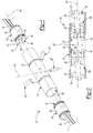
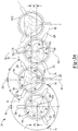
- the engine 10 may include a housing or cylinder 14, one or more piston 16, an outlet 18, an inlet 20, and at least one fuel injector or nozzle 22. With reference to FIG. 3A , while four cylinders 14 are shown, it will be appreciated that the engine 10 may include any number of cylinders 14, each including at least one piston 16, as is known in the art. As illustrated in FIG. 1 , in one configuration, the engine 10 may include two pistons 16.
- the cylinder 14 may be formed from a material such as iron, steel, or a suitable metallic alloy, and may extend along a longitudinal axis A1.
- the longitudinal axis A1 may be a central longitudinal axis A1, such that the cylinder 14 is symmetrically disposed about the longitudinal axis A1.
- the cylinder 14 may also include a transverse axis A2 extending in a direction substantially perpendicular to the longitudinal axis A1.
- a bore or passage 26 may extend through, or otherwise be defined by, the cylinder 14 along the longitudinal axis A1.
- the outlet 18 and the inlet 20 may be configured to fluidly communicate with the passage 26.
- the inlet 20 can be configured to deliver air (e.g., ambient air, air from a turbocharger or other portion of an exhaust gas regeneration system (not shown), etc.) to the passage 26 for combustion, while the outlet 18 can be configured to remove exhaust gases from the passage 26 after combustion.
- air e.g., ambient air, air from a turbocharger or other portion of an exhaust gas regeneration system (not shown), etc.
- the pistons 16 may be slidably disposed in the passage 26 of the cylinder 14 for opposed, reciprocating motion along the longitudinal axis A1.
- Each piston 16 may include a skirt 28 and a crown 30.
- the skirt 28 can be integrally or monolithically formed with the crown 30.
- the crown 30 may include a recess 32 that is at least partially formed or defined by a bottom surface 34, first side surface 36, a second side surface 38, and a third side surface 40.
- the bottom surface 34 may be concave and symmetrically disposed about the longitudinal axis A1.
- the first, second, and third side surfaces 36, 38, 40 may be substantially identical to each other.
- first, second, and third side surfaces 36, 38, 40 may extend from an end or rim 42 of the piston 16 to the bottom surface 34. Accordingly, the first, second, and third side surfaces 36, 38, 40 may be symmetrically disposed about the longitudinal axis A1. In some configurations, the first, second, and third side surfaces 36, 38, 40 may include a concave shape or profile. It will be appreciated, however, that the first, second, and third side surfaces 36, 38, 40 may include various shapes or profiles within the scope of the present disclosure.
- the recess 32 of a first piston 16a and the recess 32 of a second piston 16b may define a chamber 50 therebetween.
- the first and second pistons 16a, 16b may be disposed within the passage 26 such that the first, second, and third side surfaces 36, 38, 40 of the first piston 16a are aligned with the first, second, and third side surfaces 36, 38, 40, respectively, of the second piston 16b.
- the chamber 50 may be symmetrically disposed relative to the longitudinal axis A1.
- the chamber 50 may be symmetric relative to a cross section of the engine 10 intersecting the longitudinal axis A2 ( FIG.
- first, second, and third side surfaces 36, 38, 40 of the first piston 16a may be offset from, or otherwise have a different shape or profile than the first, second, and third side surfaces 36, 38, 40 of the second piston 16b, such that the chamber 50 may be asymmetric relative to the cross section of the engine 10 intersecting the longitudinal axis A1 ( FIG. 2 ), and/or asymmetric relative to the cross section of the engine 10 intersecting the transverse axis A2 ( FIG. 2 ).
- the first piston 16a of a first cylinder 14a may be angularly offset relative to the orientation of the first piston 16a of a second cylinder 14b.
- the first piston 16a of a third cylinder 14c may be angularly offset relative to the orientation of the first piston 16a of the second cylinder 14b.
- first piston 16a of the second cylinder 14b may be rotated by a first angle about the longitudinal axis A1b relative to the orientation of the first piston 16a of the first cylinder 14a about the longitudinal axis A1a
- first piston 16a of the third cylinder 14c may be rotated by a second angle about the longitudinal axis A1c relative to the orientation of the first piston 16a of the second cylinder 14b about the longitudinal axis A1b.
- the first angle may be substantially equal to the second angle, such that the first piston 16a of the first cylinder 14a is substantially angularly aligned with the first piston 16a of the third cylinder 14c relative to, or about, the longitudinal axes A1a and A1c.
- the second pistons 16b of the first, second, and third cylinders 14a, 14b, 14c may also be angularly offset from one another as described above with respect to the first pistons 16a.
- each piston 16 may be supported by, or otherwise coupled to, a connecting rod 54.
- the connecting rod 54 can be supported by, or otherwise coupled to, a crankshaft (not shown).
- the nozzle 22 can be disposed within, or otherwise extend through, the cylinder 14.
- the cylinder 14 may include three nozzles 22 disposed within the cylinder 14 about the longitudinal axis A1, such that each nozzle 22 is offset from an adjacent nozzle 22 by an angle ⁇ about the longitudinal axis A1.
- a first nozzle 22a may extend from the cylinder 14 along an axis Xa
- a second nozzle 22b may extend from the cylinder along an axis Xb
- a third nozzle 22c may extend from the cylinder along an axis Xc.
- the axis Xa may be offset from the axis Xb by an angle ⁇ a
- the axis Xb may be offset from the axis Xc by an angle ⁇ b
- the axis Xc may be offset from the axis Xa by an angle ⁇ c.
- the angle ⁇ a may be substantially equal to the angle ⁇ b
- the angle ⁇ b may be substantially equal to the angle ⁇ c, such that the nozzles 22a, 22b and 22c are symmetrically disposed about the longitudinal axis A1.
- the first nozzle 22a may be disposed or otherwise aligned with a point of intersection of the first and second surfaces 36, 38 of the first piston 16a
- the second nozzle 22b may be disposed or otherwise aligned with a point of intersection of the second and third surfaces 38, 40 of the first piston 16a
- the third nozzle 22c may be disposed or otherwise aligned with a point of intersection of the first and third surfaces 36, 40 of the first piston 16a.
- ⁇ a, ⁇ b, and ⁇ c may each be equal to an angle between 100 degrees and 140 degrees.
- ⁇ a, ⁇ b, and ⁇ c may each be equal to 120 degrees. It will also be appreciated that the angle ⁇ a may differ from the angle ⁇ b, and/or the angle ⁇ b may differ from the angle ⁇ c.
- the nozzles 22 may be in fluid communication with the passage 26.
- the nozzles 22 can be configured to spray or otherwise deliver a volume of fuel to the chamber 50 for combustion.
- the nozzles 22 may be aligned relative to the longitudinal axis A1.
- the nozzles 22a, 22b, 22c may deliver the volume of fuel in a direction substantially along or parallel to the axes Xa, Xb, Xc, respectively.
- the volume of fuel may be delivered in a direction that is offset from the axes Xa, Xb, Xc.
- the cylinders 14 may be positioned within the engine 10 such that the longitudinal axes A1 are substantially parallel to each other.
- cylinders 14 may be positioned within the engine such that the nozzles 22 of the first cylinder 14a are aligned with the nozzles 22 of the second and/or third cylinders 14b, 14c relative to the longitudinal axes A1b, A1c, respectively.
- the axes Xa, Xb, Xc of the nozzles 22 of one or more of the cylinders 14 may extend in, or otherwise define, a plane.
- all of the axes Xa, Xb, Xc of the nozzles 22 of the cylinders 14 may extend in, or otherwise define, a plane.
- the longitudinal axis A1a of the first cylinder 14a may also be offset from the longitudinal axis A1b of the second cylinder 14b that is adjacent to the first cylinder 14a.
- the longitudinal axis A1b may be offset in a first direction from the longitudinal axis A1a by a distance Da.
- the longitudinal axis A1c of the third cylinder 14c, that is adjacent to the second cylinder 14b may be offset in a second direction from the longitudinal axis A1b by a distance Db.
- the second direction may be opposite the first direction.
- the distance Db may be substantially equal to the distance Da, such that the longitudinal axis A1c is aligned or otherwise coplanar with the longitudinal axis A1b.
- the engine 10 may include any number (N) of cylinders 14. In this regard, it will be appreciated that each cylinder 14(N) may be offset from an adjacent cylinder 14(N-1) by the distance Da, and offset from an adjacent cylinder 14(N+1) by the distance Db.
- the nozzles 22a, 22b, 22c of the first cylinder 14a may also be angularly offset about the longitudinal axis A1a relative to the nozzles 22a, 22b, 22c, respectively, of the second cylinder 14b.
- the first nozzle 22a of the second cylinder 14b may be angularly offset about the longitudinal axis A1b relative to the orientation of the first nozzle 22a of the first cylinder 14a about the longitudinal axis A1a.
- the axis Xa of the first nozzle 22a of the first cylinder 14a may be substantially aligned with the transverse axis A2a of the first cylinder 14a, while the axis Xa of the first nozzle 22a of the second cylinder 14b may be offset from the transverse axis A2b of the second cylinder 14b by an angle ⁇ b.
- the axis Xb of the second nozzle 22b of the first cylinder 14a may be offset from the transverse axis A2a of the first cylinder 14a by the angle ⁇ a, while the axis Xb of the second nozzle 22b of the second cylinder 14b may be substantially aligned with the transverse axis A2b of the second cylinder 14b.
- the axis Xc of the third nozzle 22c of the first cylinder 14a may be offset from the transverse axis A2a of the first cylinder 14a by the angle ⁇ c
- the axis Xc of the third nozzle 22c of the second cylinder 14b may be offset from the transverse axis A2b of the second cylinder 14b by an angle ⁇ c.
- the angles ⁇ a, ⁇ b, and ⁇ c may be substantially equal to each other.
- the axis Xa of the first nozzle 22a of the first cylinder 14a may be offset from the axis Xa of the first nozzle 22a of the second cylinder 14b by an angle between 45 and 75 degrees, and in some configurations, substantially equal to 60 degrees.
- the axes Xb, Xc of the second and third nozzles 22b, 22c of the first cylinder 14a may be offset from the axes Xb, Xc, respectively, of the second and third nozzles 22b, 22c of the second cylinder 14b by an angle between 45 and 75 degrees, and in some configurations, substantially equal to 60 degrees.
- the configuration of the cylinders 14, including the distances Da and Db, the configuration of the nozzles 22a, 22b, 22c, including the angles ⁇ and ⁇ , and the configuration of the pistons 16a, 16b, can allow for the closest possible arrangement of the cylinders 14 within the engine 10 having three nozzles 22.
- arranging the cylinders 14 and the nozzles 22a, 22b, 22c in the manner described can help to prevent the nozzles 22a, 22b, 22c from contacting or otherwise interfering with an adjacent cylinder 14 and/or the nozzles 22a, 22b, 22c of the adjacent cylinder 14, thus allowing for a reduction in the size of the engine 10.
- the inclusion of three nozzles 22 within the engine 10 can help to ensure improved combustion performance, including efficient utilization and combustion of air within the chamber 50, as well as the efficient mixing of fuel from each of the nozzles 22 within the chamber 50.
- FIG. 3B another example of an engine is labelled 10a.
- the engine 10a is substantially similar to the engine 10 such that only differences between the engines 10, 10a will now be described.
- the longitudinal axis A1b of the second cylinder 14b is offset in a first direction from the longitudinal axis A1a of the first cylinder 14a.
- the longitudinal axis A1c of the third cylinder 14c is offset in a second direction from the longitudinal axis A1b, where the second direction is opposite from the first direction.
- the longitudinal axes A1a, A1b, A1c, of the first, second, and third cylinders 14a, 14b, and 14c are aligned with one another such that the longitudinal axes A1a, A1b, A1c all lie within the same plane.
- the angles ⁇ a, ⁇ b, and ⁇ c between the axes Xa, Xb, Xc of the nozzles 22a, 22b, 22c are each equal to 120 degrees.
- the nozzles 22a, 22b, 22c are symmetrically disposed about the longitudinal axes A1a, A1b, A1c of the first, second, and third cylinders 14a, 14b, and 14c.
- the angle ⁇ a between the first and second nozzles 22a and 22b is less than the angle ⁇ b between the second and third nozzles 22a and 22b and less than the angle ⁇ c between the first and third nozzles 22a and 22c.
- the angles ⁇ b and ⁇ c are equal to each other such that the distal ends of the nozzles 22a, 22b, 22c form an isosceles triangle 53.
- the angle ⁇ a is between 60 degrees and 120 degrees (e.g., 70 degrees), and each of the angles ⁇ b and ⁇ c are between 150 degrees and 120 degrees (e.g., 145 degrees).
- each of the angles ⁇ b and ⁇ c may be determined by subtracting the angle ⁇ a from 360 degrees and dividing the result by two.
- the shape of the crown 30 of the pistons 16 in the engine 10a is different than the shape of the crown 30 of the pistons 16 in the engine 10.
- the first, second, and third side surfaces 36, 38, and 40 of the recess 32 are disposed adjacent to the first, second, and third nozzles 22a, 22b, and 22c, respectively.
- the first, second, and third side surfaces 36, 38, and 40 have elongated, concave shapes that are centered about the axis Xa, Xb, or Xc of a corresponding one of the first, second, and third nozzles 22a, 22b, and 22c.
- first, second, and third side surfaces 36, 38, and 40 accommodate the spray patterns of the first, second, and third nozzles 22a, 22b, and 22c, respectively.
- the bottom surface 34 of the recess 32 has a hemispherical, concave shape that provides fluid communication between the elongated, concave shapes formed by the first, second, and third side surfaces 36, 38, and 40.
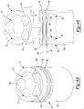
- FIG. 4B another example of one of the pistons 16 of the engine 10 or 10a is shown.
- the crown 30 of the piston 16 may not be flat.
- the recess 32 may be inset or depressed in the crown 30 of the piston 16 relative to the rim 42 of the piston 16.
- the piston 16 includes one or more piston rings 56 that extend annularly about the piston 16.
- Each of the piston rings 56 defines a ring plane 58, which may be transverse to the skirt 28.
- the piston rings 56 abut and seal against the cylinder 14 (see FIG. 1 ) to prevent the blow-by of combustion gases. Limiting the operational temperatures of the piston rings 56 to avoid ring failure is critical to the design of the engine 10. Overheating of the piston rings 56, and ultimately ring failure, can be caused by combustion related heat and/or heat generated by friction between the piston rings 56 and the cylinder 14.
- the piston 16 may be provided with a cooling gallery 60 that functions to draw heat away from the piston rings 56.
- the cooling gallery 60 may have an annular shape and may be disposed within the piston 16 inwardly of the crown 30.
- the cooling gallery 60 is hollow and may include openings 62 that allow oil within passage 26 (see FIG. 1 ) to enter and exit the cooling gallery 60 in order to carry heat away from the crown 30.
- improved thermal management (i.e. cooling) of the piston 16 may be achieved.
- the piston 16 may be coated with a ceramic material 64 for improved heat resistance.
- the piston 16 itself may be made of a variety of different materials.
- the piston 16 may be made of a steel alloy, an aluminum alloy, or cast iron. These materials are generally good thermal conductors such that the heat experienced by the crown 30 is transferred through the piston 16 and to the piston rings 56.
- the ceramic material 64 coating the piston 16 reduces heat transfer between hot combustion gases in the chamber 50 (see FIG. 2 ) and the crown 30 of the piston 16 and therefore reduces the amount of heat that is transferred from the piston 16 to the piston rings 56.
- the ceramic material 64 coating the piston 16 helps insulate the piston 16 from hot combustion gases and therefore reduces the temperature of the piston 16. Because the piston 16 is kept at a lower temperature as a result of the ceramic material 64, the amount of heat that is transferred from the piston 16 to the piston rings 56 is reduced. This ultimately lowers the operating temperature of the piston rings 56.
- the ceramic material 64 coating the piston 16 may be applied using known manufacturing techniques.
- a thermal cap 66 of the crown 30 may be formed separate from a base 68 of the crown 30 and secured to or retained on the base 68.
- the thermal cap 66 can be made of the ceramic material, and the base 68 can be made of a metal material.
- FIG. 4B the thermal cap 66 is shown separated from the base 68 and slightly tilted with respect to the base 68 in a direction D1 about a transverse axis T1.
- the thermal cap 66 may be retained on the base 68 in a variety of different ways.
- the thermal cap 66 may be retained on the base 68 by a mechanical connection, friction welding, thermal welding, or by an adhesive.
- the thermal cap 66 defines the top surface of the crown 30 of the piston 16 shown in FIG. 4B .
- the thermal cap 66 helps insulate the piston 16 from hot combustion gases within the chamber 50. Again, this decreases operational temperatures at the piston rings 56, which leads to improved piston ring function and increased service life.
- the thermal cap 66 may be used in place of or in addition to the cooling gallery 60.
- the strength of the piston 16 is not compromised because the hollow cooling gallery 60 and the associated stress risers that the cooling gallery 60 creates in the piston 16 are eliminated.
- the piston 16 is more resistant to deflection caused by operational forces, including forces resulting from combustion, friction, inertia, and thermal expansion of the piston 16, the piston rings 16, and/or the cylinder 14. Additionally, because the hollow cooling gallery 60 may be eliminated, the piston 16 may be made without complex machining operations, reducing manufacturing time and costs.
- the example piston 16 shown in FIG. 4A includes the piston rings 56 described with reference to the example piston 16 shown in FIG. 4B .
- the example piston 16 shown in FIGS. 1, 2 , and 3A may incorporate various features described with reference to the example piston 16 shown in in FIG. 4B .
- the example piston 16 shown in FIGS. 1, 2 , and 3A may be provided with the cooling gallery 60, may be coated with the ceramic material 64, and/or may include the thermal cap 66 formed separate from and joined to the base 68.
- Example embodiments are provided so that this disclosure will be thorough, and will fully convey the scope of the appended claims to those who are skilled in the art. Numerous specific details are set forth such as examples of specific components, devices, and methods, to provide a thorough understanding of embodiments of the present disclosure as defined by the appended claims. It will be apparent to those skilled in the art that specific details need not be employed, that example embodiments may be embodied in many different forms and that neither should be construed to limit the scope of the appended claims. In some example embodiments, well-known processes, well-known device structures, and well-known technologies are not described in detail.
- first, second, third, etc. may be used herein to describe various elements, components, regions, layers and/or sections, these elements, components, regions, layers and/or sections should not be limited by these terms. These terms may be only used to distinguish one element, component, region, layer or section from another region, layer or section. Terms such as “first,” “second,” and other numerical terms when used herein do not imply a sequence or order unless clearly indicated by the context. Thus, a first element, component, region, layer or section discussed below could be termed a second element, component, region, layer or section without departing from the teachings of the example embodiments.
- spatially relative terms such as “inner,” “outer,” “beneath,” “below,” “lower,” “above,” “upper,” and the like, may be used herein for ease of description to describe one element or feature's relationship to another element(s) or feature(s) as illustrated in the figures.
- Spatially relative terms may be intended to encompass different orientations of the device in use or operation in addition to the orientation depicted in the figures. For example, if the device in the figures is turned over, elements described as “below” or “beneath” other elements or features would then be oriented “above” the other elements or features.
- the example term “below” can encompass both an orientation of above and below.
- the device may be otherwise oriented (rotated 90 degrees or at other orientations) and the spatially relative descriptors used herein interpreted accordingly.
Landscapes
- Engineering & Computer Science (AREA)
- Mechanical Engineering (AREA)
- General Engineering & Computer Science (AREA)
- Chemical & Material Sciences (AREA)
- Combustion & Propulsion (AREA)
- Combustion Methods Of Internal-Combustion Engines (AREA)
- Fuel-Injection Apparatus (AREA)
Claims (10)
- Gegenkolbenkraftmaschine (10, 10a), die Folgendes aufweist:einen ersten Zylinder (14, 14a), einen ersten Kanal (26, 26a) definierend, sich entlang einer ersten Längsachse (A1, A1a) erstreckend;erste, zweite und dritte Kraftstoffeinspritzdüsen (22a, 22b, 22c) in Fluidverbindung mit dem ersten Kanal (26, 26a), wobei die erste, zweite und dritte Kraftstoffeinspritzdüse (22a, 22b, 22c) erste, zweite bzw. dritte Düsenachsen (Xa, Xb, Xc) aufweisen, die in einer gemeinsamen Ebene angeordnet sind, die senkrecht zur ersten Längsachse (A1, A1a) ist, wobei zumindest eine der ersten, zweiten und dritten Düsenachsen (Xa, Xb, Xc) bezüglich einer anderen der ersten, zweiten und dritten Düsenachsen (Xa, Xb, Xc) um einen schrägen Winkel (βa, βb, βc) um die erste Längsachse (A1, A1a) winkelversetzt ist;einen zweiten Zylinder (14b, 14c), einen zweiten Kanal (26) definierend, sich entlang einer zweiten Längsachse (A1b, A1c) erstreckend, die im Wesentlichen parallel zur ersten Längsachse (A1, A1a) ist; undvierte, fünfte und sechste Kraftstoffeinspritzdüsen (22a, 22b, 22c) in Fluidverbindung mit dem zweiten Kanal (26, 26a), wobei die vierte, fünfte und sechste Kraftstoffeinspritzdüse (22a, 22b, 22c) vierte, fünfte bzw. sechste Düsenachsen (Xa, Xb, Xc), aufweisen, die in einer gemeinsamen Ebene angeordnet sind, die senkrecht zur zweiten Längsachse (A1b, A1c) ist, wobei die vierte, fünfte und sechste Düsenachse (Xa, Xb, Xc) die zweite Längsachse (A1b, A1c) schneiden,dadurch gekennzeichnet, dass:die erste Kraftstoffeinspritzdüse (22a) bezüglich der zweiten Kraftstoffeinspritzdüse (22b) um einen ersten Winkel (βa) um die erste Längsachse (A1, A1a) winkelversetzt ist;die zweite Kraftstoffeinspritzdüse (22b) bezüglich der dritten Einspritzdüse (22c) um einen zweiten Winkel (βb) um die erste Längsachse (A1, A1a) winkelversetzt ist;die dritte Kraftstoffeinspritzdüse (22c) bezüglich der ersten Einspritzdüse (22a) um einen dritten Winkel (βc) um die erste Längsachse (A1, A1a) winkelversetzt ist;die vierte Kraftstoffeinspritzdüse (22a) bezüglich der fünften Kraftstoffeinspritzdüse (22b) um den ersten Winkel (βa) um die zweite Längsachse (A1b, A1c) winkelversetzt ist;die fünfte Kraftstoffeinspritzdüse (22b) bezüglich der sechsten Kraftstoffeinspritzdüse (22c) um den zweiten Winkel (βb) um die zweite Längsachse (A1b, A1c) winkelversetzt ist; unddie sechste Kraftstoffeinspritzdüse (22c) bezüglich der vierten Kraftstoffeinspritzdüse (22a) um den dritten Winkel (βc) um die zweite Längsachse (A1b, A1c) winkelversetzt ist;wobei der erste und der dritte Winkel (βa, βc) einander gleich und größer als der zweite Winkel (βb) sind.
- Gegenkolbenkraftmaschine nach Anspruch 1, wobei die Ausrichtung der vierten Kraftstoffeinspritzdüse (22a) um die zweite Längsachse (A1b, A1c) winklig auf die Ausrichtung der ersten Kraftstoffeinspritzdüse (22a) um die erste Längsachse (A1, A1a) ausgerichtet ist.
- Gegenkolbenkraftmaschine nach Anspruch 1, wobei die Ausrichtung der vierten Kraftstoffeinspritzdüse (22a) um die zweite Längsachse (A1b, A1c) bezüglich der Ausrichtung der ersten Kraftstoffeinspritzdüse (22a) um die erste Längsachse (A1, A1a) winkelversetzt ist.
- Gegenkolbenkraftmaschine nach Anspruch 3, wobei die Ausrichtung der vierten Kraftstoffeinspritzdüse (22a) um die zweite Längsachse (A1b, A1c) bezüglich der Ausrichtung der ersten Kraftstoffeinspritzdüse (22a) um die erste Längsachse (A1, A1a) um einen Winkel, der zwischen 45 Grad und 75 Grad ist, winkelversetzt ist.
- Gegenkolbenkraftmaschine nach einem der Ansprüche 1 bis 4, wobei die zweite Längsachse (A1b, A1c) gegenüber der ersten Längsachse (A1, A1a) um einen ersten Abstand (Da) versetzt ist, sich in eine erste Richtung im Wesentlichen senkrecht zur ersten Längsachse (A1, A1a) erstreckend.
- Gegenkolbenkraftmaschine nach einem der Ansprüche 1 bis 5, die ferner Folgendes aufweist:einen dritten Zylinder (14b), einen dritten Kanal (26) definierend, sich entlang einer dritten Längsachse (A1b) erstreckend, die im Wesentlichen parallel zur ersten und zweiten Längsachse (A1a, A1c) ist, wobei der dritte Zylinder zwischen dem ersten und dem zweiten Zylinder angeordnet ist, wobei die dritte Längsachse gegenüber der ersten und zweiten Längsachse um einen zweiten Abstand (Db) versetzt ist, sich in eine Richtung im Wesentlichen senkrecht zur ersten und zweiten Längsachse erstreckend; undsiebte, achte und neunte Kraftstoffeinspritzdüsen (22a, 22b, 22c), umlaufend um die dritte Längsachse angeordnet und in Fluidverbindung mit dem dritten Kanal.
- Gegenkolbenkraftmaschine nach Anspruch 6, wobei die erste und dritte Längsachse eine erste Ebene definieren.
- Gegenkolbenkraftmaschine nach Anspruch 7, die ferner einen vierten Zylinder (14N) aufweist, einen vierten Kanal (26) definierend, sich entlang einer vierten Längsachse erstreckend, wobei die vierte Längsachse im Wesentlichen parallel zur ersten, zweiten und dritten Längsachse ist, die vierte Längsachse gegenüber der dritten Längsachse um einen dritten Abstand (Da) versetzt ist, sich in eine dritte Richtung im Wesentlichen senkrecht zur dritten Längsachse erstreckend.
- Gegenkolbenkraftmaschine nach Anspruch 8, wobei die zweite und vierte Längsachse eine zweite Ebene definieren.
- Gegenkolbenkraftmaschine nach einem der vorhergehenden Ansprüche, die ferner ein Paar Kolben (16a, 16b) aufweist, gleitbar in dem Kanal jedes Zylinders angeordnet.
Applications Claiming Priority (2)
| Application Number | Priority Date | Filing Date | Title |
|---|---|---|---|
| US201562126009P | 2015-02-27 | 2015-02-27 | |
| US15/050,878 US10066590B2 (en) | 2015-02-27 | 2016-02-23 | Opposed piston three nozzle combustion chamber design |
Publications (2)
| Publication Number | Publication Date |
|---|---|
| EP3061906A1 EP3061906A1 (de) | 2016-08-31 |
| EP3061906B1 true EP3061906B1 (de) | 2019-07-10 |
Family
ID=55650045
Family Applications (1)
| Application Number | Title | Priority Date | Filing Date |
|---|---|---|---|
| EP16157545.1A Active EP3061906B1 (de) | 2015-02-27 | 2016-02-26 | Brennkammerdesign mit gegenkolben und drei düsen |
Country Status (2)
| Country | Link |
|---|---|
| US (1) | US10066590B2 (de) |
| EP (1) | EP3061906B1 (de) |
Families Citing this family (4)
| Publication number | Priority date | Publication date | Assignee | Title |
|---|---|---|---|---|
| US10731259B2 (en) * | 2016-11-04 | 2020-08-04 | Cummins Inc. | Pistons with thermal barrier coatings |
| US10724467B2 (en) | 2016-11-04 | 2020-07-28 | Cummins Inc. | Pistons with thermal barrier coatings |
| CN109339946A (zh) * | 2018-11-15 | 2019-02-15 | 北京理工大学 | 一种基于气门换气的双曲轴对置活塞四冲程发动机 |
| GB202014614D0 (en) * | 2020-09-16 | 2020-10-28 | Carnot Ltd | Internal combustion engine |
Citations (1)
| Publication number | Priority date | Publication date | Assignee | Title |
|---|---|---|---|---|
| US1143408A (en) * | 1913-01-18 | 1915-06-15 | Gen Electric | Internal-combustion engine. |
Family Cites Families (59)
| Publication number | Priority date | Publication date | Assignee | Title |
|---|---|---|---|---|
| US1127772A (en) * | 1913-01-02 | 1915-02-09 | Hugo Junkers | Internal-combustion engine. |
| US1486583A (en) | 1923-01-26 | 1924-03-11 | William M Huskisson | Internal-combustion engine |
| US2463418A (en) | 1942-04-30 | 1949-03-01 | Pescara Raul Pateras | Fuel injection system |
| US3007462A (en) * | 1957-08-26 | 1961-11-07 | Vernon W Balzer | Reciprocating machine |
| GB1014831A (en) | 1961-06-26 | 1965-12-31 | James Abraham Hardman | Improvements in or relating to internal combustion engines |
| US3407790A (en) | 1967-04-12 | 1968-10-29 | Anker K. Antonsen | Uniflow scavenged engine having improved gaseous fuel admission |
| FR2145081A5 (de) | 1971-07-08 | 1973-02-16 | Peugeot & Renault | |
| DE2500644C2 (de) | 1975-01-09 | 1988-07-07 | Klöckner-Humboldt-Deutz AG, 5000 Köln | Kraftstoffeinspritzventil für Brennkraftmaschinen |
| US4043301A (en) | 1975-06-20 | 1977-08-23 | Templet Industries Incorporated | Internal combustion engine |
| DE2849783A1 (de) | 1978-04-25 | 1979-11-08 | Charles Gwin Renegar | Verbrennungskraftmaschine mit gegenueberliegenden, gefuehrten kolben und nockenantrieben |
| US4709679A (en) | 1985-03-25 | 1987-12-01 | Stanadyne, Inc. | Modular accumulator injector |
| US4872433A (en) * | 1987-12-07 | 1989-10-10 | Paul Marius A | Combustion chamber configurations for two cycle engines |
| US5042441A (en) * | 1989-10-03 | 1991-08-27 | Paul Marius A | Low emission combustion system for internal combustion engines |
| IT1288748B1 (it) | 1996-10-11 | 1998-09-24 | Iveco Fiat | Iniettore di combustibile per un motore endotermico e motore endotermico provvisto di tale iniettore |
| US6170443B1 (en) | 1998-09-11 | 2001-01-09 | Edward Mayer Halimi | Internal combustion engine with a single crankshaft and having opposed cylinders with opposed pistons |
| DE19937713C1 (de) | 1999-08-10 | 2001-03-15 | Siemens Ag | Steuerventilanordnung zum Einsatz in einem Kraftstoffinjektor für Verbrennungsmotoren |
| ITPZ990004A1 (it) | 1999-10-04 | 2001-04-04 | Cosimo Sarno | Sistemi pluri-iniettori. |
| US6526927B1 (en) * | 2000-10-03 | 2003-03-04 | Dennis C. Palmer | Internal combustion engine |
| US6595188B2 (en) | 2001-12-04 | 2003-07-22 | Caterpillar Inc | Compact valve assembly and fuel injector using same |
| JP4576884B2 (ja) | 2004-05-19 | 2010-11-10 | トヨタ自動車株式会社 | 内燃機関の制御装置および制御方法 |
| US7360511B2 (en) | 2004-06-10 | 2008-04-22 | Achates Power, Inc. | Opposed piston engine |
| US7334570B2 (en) | 2005-04-01 | 2008-02-26 | Achates Power, Inc. | Common rail fuel injection system with accumulator injectors |
| JP2009103085A (ja) | 2007-10-25 | 2009-05-14 | Suzuki Motor Corp | 2サイクルエンジンの燃料噴射制御装置 |
| DE102007056913A1 (de) | 2007-11-26 | 2009-05-28 | Robert Bosch Gmbh | Einspritzdüse für Kraftstoff mit Kugelventil |
| US8151747B2 (en) | 2009-04-07 | 2012-04-10 | Scuderi Group, Llc | Crescent-shaped recess in piston of a split-cycle engine |
| DE202009017699U1 (de) | 2009-11-18 | 2010-09-23 | Daude, Otto, Dr.-Ing. MBA | Tangential am Zylinderumfang ausgerichtete Einspritzdüsen für Verbrennungsmotoren mit Gaswechselsteuerung |
| US8800528B2 (en) | 2010-04-27 | 2014-08-12 | Achates Power, Inc. | Combustion chamber constructions for opposed-piston engines |
| US10180115B2 (en) | 2010-04-27 | 2019-01-15 | Achates Power, Inc. | Piston crown bowls defining combustion chamber constructions in opposed-piston engines |
| US9512779B2 (en) | 2010-04-27 | 2016-12-06 | Achates Power, Inc. | Swirl-conserving combustion chamber construction for opposed-piston engines |
| WO2011146110A1 (en) | 2010-05-18 | 2011-11-24 | Achates Powers, Inc. | Fuel injector support constructions for direct injection opposed-piston engines |
| JP5946831B2 (ja) * | 2010-08-16 | 2016-07-06 | アカーテース パワー,インク. | 対向ピストンエンジン用の燃料噴射噴霧パターン |
| JP5161278B2 (ja) | 2010-09-22 | 2013-03-13 | 日立オートモティブシステムズ株式会社 | 内燃機関の燃料噴射制御装置 |
| US20120192831A1 (en) | 2011-01-27 | 2012-08-02 | Ecomotors International, Inc. | Combustion Chamber for a Side-Mounted Direction Injector |
| DE102011101005A1 (de) | 2011-04-20 | 2012-10-25 | Daimler Ag | Kolben für eine Hubkolben-Brennkraftmaschine |
| EP2712394B1 (de) | 2011-05-18 | 2016-12-14 | Achates Power, Inc. | Brennkammerkonstruktion für motoren mit entgegengesetzten kolben |
| US9631569B2 (en) | 2014-08-04 | 2017-04-25 | General Electric Company | System and method for controlling operation of an engine |
| GB2491155B (en) | 2011-05-24 | 2013-04-10 | Cox Powertrain Ltd | Opposed piston engine having injector located within cylinder |
| GB2493061A (en) * | 2011-07-15 | 2013-01-23 | Ecomotors Internat Inc | Opposed piston engine with toroidal combustion chamber |
| GB2493260A (en) | 2011-07-26 | 2013-01-30 | Ecomotors Internat Inc | Opposed piston engine with tumble flow in shaped combustion chamber |
| US20130036999A1 (en) | 2011-08-08 | 2013-02-14 | Ecomotors International, Inc. | High-Squish Combustion Chamber With Side Injection |
| US20130104848A1 (en) | 2011-10-27 | 2013-05-02 | Achates Power, Inc. | Fuel Injection Strategies in Opposed-Piston Engines with Multiple Fuel Injectors |
| DE102012111776A1 (de) | 2011-12-09 | 2013-06-13 | Ecomotors International, Inc. | Gegenkolbenmotor mit ringförmiger Brennkammer mit Seiteneinspritzung |
| US8783015B2 (en) | 2011-12-15 | 2014-07-22 | Ecomotors, Inc. | Shared EGR system and method for a dual-module engine |
| CN102588075A (zh) | 2012-03-13 | 2012-07-18 | 深圳市世纪经纬数据系统有限公司 | 一种缸内多点喷射的内燃机 |
| JP5984469B2 (ja) | 2012-04-11 | 2016-09-06 | 三菱重工業株式会社 | 二元燃料ディーゼルエンジン |
| DE102012104212A1 (de) | 2012-04-18 | 2013-10-24 | Ecomotors International, Inc. | Symmetrischer Motor mit gegenüberliegenden Kolben und gegenüberliegenden Zylindern |
| EP2672101A1 (de) | 2012-06-05 | 2013-12-11 | Caterpillar Motoren GmbH & Co. KG | Einspritzdüse |
| DE102012210937A1 (de) | 2012-06-27 | 2014-01-23 | Robert Bosch Gmbh | Verfahren zur Steuerung einer Brennkraftmaschine und System mit einer Brennkraftmaschine und einem Steuergerät |
| JP5869443B2 (ja) | 2012-07-27 | 2016-02-24 | 本田技研工業株式会社 | 内燃機関のピストン構造 |
| US9267421B2 (en) | 2012-08-24 | 2016-02-23 | Mazda Motor Corporation | Combustion chamber structure for engine |
| JP2015529783A (ja) * | 2012-09-25 | 2015-10-08 | アカーテース パワー,インク. | 対向ピストンエンジンにおけるスワールスプレーパターンの燃料噴射 |
| JP5652466B2 (ja) | 2012-12-21 | 2015-01-14 | トヨタ自動車株式会社 | 内燃機関のピストン及び内燃機関 |
| GB2515254B (en) | 2013-04-05 | 2016-07-20 | Osp Engines Ltd | Opposed stepped piston engine power cylinder lubrication system |
| WO2015020867A1 (en) * | 2013-08-05 | 2015-02-12 | Achates Power, Inc. | Dual-fuel constructions for opposed-piston engines with shaped combustion chambers |
| US9211797B2 (en) | 2013-11-07 | 2015-12-15 | Achates Power, Inc. | Combustion chamber construction with dual mixing regions for opposed-piston engines |
| JP6384657B2 (ja) | 2014-06-30 | 2018-09-05 | 三菱自動車工業株式会社 | 燃料噴射制御装置 |
| US9903270B2 (en) * | 2014-08-01 | 2018-02-27 | Avl Powertrain Engineering, Inc. | Cylinder arrangement for opposed piston engine |
| GB2530761A (en) | 2014-10-01 | 2016-04-06 | Delphi Internat Operations Luxembourg S Ã R L | Fuel injection equipment |
| US10161371B2 (en) * | 2015-02-27 | 2018-12-25 | Avl Powertrain Engineering, Inc. | Opposed piston three nozzle piston bowl design |
-
2016
- 2016-02-23 US US15/050,878 patent/US10066590B2/en active Active
- 2016-02-26 EP EP16157545.1A patent/EP3061906B1/de active Active
Patent Citations (1)
| Publication number | Priority date | Publication date | Assignee | Title |
|---|---|---|---|---|
| US1143408A (en) * | 1913-01-18 | 1915-06-15 | Gen Electric | Internal-combustion engine. |
Also Published As
| Publication number | Publication date |
|---|---|
| US10066590B2 (en) | 2018-09-04 |
| US20160252065A1 (en) | 2016-09-01 |
| EP3061906A1 (de) | 2016-08-31 |
Similar Documents
| Publication | Publication Date | Title |
|---|---|---|
| US8783218B2 (en) | Toroidal combustion chamber with side injection | |
| EP3061906B1 (de) | Brennkammerdesign mit gegenkolben und drei düsen | |
| US20130276740A1 (en) | Two-piece friction-welded piston | |
| EP2978962B1 (de) | Kolbenwärmeverwaltung in einem motor mit versetzten kolben | |
| CN105525982B (zh) | 用于内燃发动机的预燃室组件 | |
| US10036344B2 (en) | Opposed piston two stroke engine liner construction | |
| CN111033009B (zh) | 用于对置活塞发动机的具有对置喷射区域的活塞组件 | |
| US10161371B2 (en) | Opposed piston three nozzle piston bowl design | |
| CN109072397B (zh) | 用于内燃发动机的气缸的活塞 | |
| CN118056068A (zh) | 具有用于喷射器夹持负荷的中间甲板反作用的燃料喷射器套筒的气缸盖组件 | |
| US9771861B2 (en) | Opposed piston two-stroke engine with thermal barrier | |
| CN104884778A (zh) | 用于内燃发动机的气缸盖 | |
| RU2002104011A (ru) | Двигатель, имеющий адиабатические элементы в его камерах сгорания, двигатель, способный использовать энергию выхлопных газов, и реактивная установка высокого давления, имеющая этот двигатель | |
| JP6490440B2 (ja) | モノブロックエンジンのシリンダー構造 | |
| KR101968490B1 (ko) | 내연 엔진용 피스톤 링 | |
| CN109386398B (zh) | 抗疲劳性活塞碗边缘 | |
| US10578049B2 (en) | Thermal barrier coating for engine combustion component | |
| US6463903B1 (en) | Piston assembly for free piston internal combustion engine | |
| EP2726724B1 (de) | Kolben mit einer unterbodenträgerfunktion | |
| US20260022677A1 (en) | Piston Assembly | |
| EP3260693A1 (de) | Zylinderkopf und motor | |
| CN112805463B (zh) | 抗爆活塞 | |
| US20160053713A1 (en) | Piston for Use in an Engine | |
| CN114623232A (zh) | 用于活塞的刮油环 | |
| WO2022202746A1 (ja) | 対向ピストンエンジン |
Legal Events
| Date | Code | Title | Description |
|---|---|---|---|
| PUAI | Public reference made under article 153(3) epc to a published international application that has entered the european phase |
Free format text: ORIGINAL CODE: 0009012 |
|
| AK | Designated contracting states |
Kind code of ref document: A1 Designated state(s): AL AT BE BG CH CY CZ DE DK EE ES FI FR GB GR HR HU IE IS IT LI LT LU LV MC MK MT NL NO PL PT RO RS SE SI SK SM TR |
|
| AX | Request for extension of the european patent |
Extension state: BA ME |
|
| STAA | Information on the status of an ep patent application or granted ep patent |
Free format text: STATUS: REQUEST FOR EXAMINATION WAS MADE |
|
| 17P | Request for examination filed |
Effective date: 20170221 |
|
| RBV | Designated contracting states (corrected) |
Designated state(s): AL AT BE BG CH CY CZ DE DK EE ES FI FR GB GR HR HU IE IS IT LI LT LU LV MC MK MT NL NO PL PT RO RS SE SI SK SM TR |
|
| STAA | Information on the status of an ep patent application or granted ep patent |
Free format text: STATUS: EXAMINATION IS IN PROGRESS |
|
| 17Q | First examination report despatched |
Effective date: 20171026 |
|
| GRAP | Despatch of communication of intention to grant a patent |
Free format text: ORIGINAL CODE: EPIDOSNIGR1 |
|
| STAA | Information on the status of an ep patent application or granted ep patent |
Free format text: STATUS: GRANT OF PATENT IS INTENDED |
|
| INTG | Intention to grant announced |
Effective date: 20190123 |
|
| GRAS | Grant fee paid |
Free format text: ORIGINAL CODE: EPIDOSNIGR3 |
|
| GRAA | (expected) grant |
Free format text: ORIGINAL CODE: 0009210 |
|
| STAA | Information on the status of an ep patent application or granted ep patent |
Free format text: STATUS: THE PATENT HAS BEEN GRANTED |
|
| AK | Designated contracting states |
Kind code of ref document: B1 Designated state(s): AL AT BE BG CH CY CZ DE DK EE ES FI FR GB GR HR HU IE IS IT LI LT LU LV MC MK MT NL NO PL PT RO RS SE SI SK SM TR |
|
| REG | Reference to a national code |
Ref country code: GB Ref legal event code: FG4D |
|
| REG | Reference to a national code |
Ref country code: CH Ref legal event code: EP Ref country code: AT Ref legal event code: REF Ref document number: 1153769 Country of ref document: AT Kind code of ref document: T Effective date: 20190715 |
|
| REG | Reference to a national code |
Ref country code: DE Ref legal event code: R096 Ref document number: 602016016512 Country of ref document: DE |
|
| REG | Reference to a national code |
Ref country code: IE Ref legal event code: FG4D |
|
| REG | Reference to a national code |
Ref country code: NL Ref legal event code: MP Effective date: 20190710 |
|
| REG | Reference to a national code |
Ref country code: LT Ref legal event code: MG4D |
|
| REG | Reference to a national code |
Ref country code: AT Ref legal event code: MK05 Ref document number: 1153769 Country of ref document: AT Kind code of ref document: T Effective date: 20190710 |
|
| PG25 | Lapsed in a contracting state [announced via postgrant information from national office to epo] |
Ref country code: FI Free format text: LAPSE BECAUSE OF FAILURE TO SUBMIT A TRANSLATION OF THE DESCRIPTION OR TO PAY THE FEE WITHIN THE PRESCRIBED TIME-LIMIT Effective date: 20190710 Ref country code: LT Free format text: LAPSE BECAUSE OF FAILURE TO SUBMIT A TRANSLATION OF THE DESCRIPTION OR TO PAY THE FEE WITHIN THE PRESCRIBED TIME-LIMIT Effective date: 20190710 Ref country code: HR Free format text: LAPSE BECAUSE OF FAILURE TO SUBMIT A TRANSLATION OF THE DESCRIPTION OR TO PAY THE FEE WITHIN THE PRESCRIBED TIME-LIMIT Effective date: 20190710 Ref country code: NO Free format text: LAPSE BECAUSE OF FAILURE TO SUBMIT A TRANSLATION OF THE DESCRIPTION OR TO PAY THE FEE WITHIN THE PRESCRIBED TIME-LIMIT Effective date: 20191010 Ref country code: SE Free format text: LAPSE BECAUSE OF FAILURE TO SUBMIT A TRANSLATION OF THE DESCRIPTION OR TO PAY THE FEE WITHIN THE PRESCRIBED TIME-LIMIT Effective date: 20190710 Ref country code: BG Free format text: LAPSE BECAUSE OF FAILURE TO SUBMIT A TRANSLATION OF THE DESCRIPTION OR TO PAY THE FEE WITHIN THE PRESCRIBED TIME-LIMIT Effective date: 20191010 Ref country code: NL Free format text: LAPSE BECAUSE OF FAILURE TO SUBMIT A TRANSLATION OF THE DESCRIPTION OR TO PAY THE FEE WITHIN THE PRESCRIBED TIME-LIMIT Effective date: 20190710 Ref country code: PT Free format text: LAPSE BECAUSE OF FAILURE TO SUBMIT A TRANSLATION OF THE DESCRIPTION OR TO PAY THE FEE WITHIN THE PRESCRIBED TIME-LIMIT Effective date: 20191111 Ref country code: AT Free format text: LAPSE BECAUSE OF FAILURE TO SUBMIT A TRANSLATION OF THE DESCRIPTION OR TO PAY THE FEE WITHIN THE PRESCRIBED TIME-LIMIT Effective date: 20190710 |
|
| PG25 | Lapsed in a contracting state [announced via postgrant information from national office to epo] |
Ref country code: ES Free format text: LAPSE BECAUSE OF FAILURE TO SUBMIT A TRANSLATION OF THE DESCRIPTION OR TO PAY THE FEE WITHIN THE PRESCRIBED TIME-LIMIT Effective date: 20190710 Ref country code: AL Free format text: LAPSE BECAUSE OF FAILURE TO SUBMIT A TRANSLATION OF THE DESCRIPTION OR TO PAY THE FEE WITHIN THE PRESCRIBED TIME-LIMIT Effective date: 20190710 Ref country code: LV Free format text: LAPSE BECAUSE OF FAILURE TO SUBMIT A TRANSLATION OF THE DESCRIPTION OR TO PAY THE FEE WITHIN THE PRESCRIBED TIME-LIMIT Effective date: 20190710 Ref country code: IS Free format text: LAPSE BECAUSE OF FAILURE TO SUBMIT A TRANSLATION OF THE DESCRIPTION OR TO PAY THE FEE WITHIN THE PRESCRIBED TIME-LIMIT Effective date: 20191110 Ref country code: GR Free format text: LAPSE BECAUSE OF FAILURE TO SUBMIT A TRANSLATION OF THE DESCRIPTION OR TO PAY THE FEE WITHIN THE PRESCRIBED TIME-LIMIT Effective date: 20191011 Ref country code: RS Free format text: LAPSE BECAUSE OF FAILURE TO SUBMIT A TRANSLATION OF THE DESCRIPTION OR TO PAY THE FEE WITHIN THE PRESCRIBED TIME-LIMIT Effective date: 20190710 |
|
| PG25 | Lapsed in a contracting state [announced via postgrant information from national office to epo] |
Ref country code: TR Free format text: LAPSE BECAUSE OF FAILURE TO SUBMIT A TRANSLATION OF THE DESCRIPTION OR TO PAY THE FEE WITHIN THE PRESCRIBED TIME-LIMIT Effective date: 20190710 |
|
| PG25 | Lapsed in a contracting state [announced via postgrant information from national office to epo] |
Ref country code: EE Free format text: LAPSE BECAUSE OF FAILURE TO SUBMIT A TRANSLATION OF THE DESCRIPTION OR TO PAY THE FEE WITHIN THE PRESCRIBED TIME-LIMIT Effective date: 20190710 Ref country code: DK Free format text: LAPSE BECAUSE OF FAILURE TO SUBMIT A TRANSLATION OF THE DESCRIPTION OR TO PAY THE FEE WITHIN THE PRESCRIBED TIME-LIMIT Effective date: 20190710 Ref country code: PL Free format text: LAPSE BECAUSE OF FAILURE TO SUBMIT A TRANSLATION OF THE DESCRIPTION OR TO PAY THE FEE WITHIN THE PRESCRIBED TIME-LIMIT Effective date: 20190710 Ref country code: RO Free format text: LAPSE BECAUSE OF FAILURE TO SUBMIT A TRANSLATION OF THE DESCRIPTION OR TO PAY THE FEE WITHIN THE PRESCRIBED TIME-LIMIT Effective date: 20190710 Ref country code: IT Free format text: LAPSE BECAUSE OF FAILURE TO SUBMIT A TRANSLATION OF THE DESCRIPTION OR TO PAY THE FEE WITHIN THE PRESCRIBED TIME-LIMIT Effective date: 20190710 |
|
| PG25 | Lapsed in a contracting state [announced via postgrant information from national office to epo] |
Ref country code: SK Free format text: LAPSE BECAUSE OF FAILURE TO SUBMIT A TRANSLATION OF THE DESCRIPTION OR TO PAY THE FEE WITHIN THE PRESCRIBED TIME-LIMIT Effective date: 20190710 Ref country code: IS Free format text: LAPSE BECAUSE OF FAILURE TO SUBMIT A TRANSLATION OF THE DESCRIPTION OR TO PAY THE FEE WITHIN THE PRESCRIBED TIME-LIMIT Effective date: 20200224 Ref country code: SM Free format text: LAPSE BECAUSE OF FAILURE TO SUBMIT A TRANSLATION OF THE DESCRIPTION OR TO PAY THE FEE WITHIN THE PRESCRIBED TIME-LIMIT Effective date: 20190710 Ref country code: CZ Free format text: LAPSE BECAUSE OF FAILURE TO SUBMIT A TRANSLATION OF THE DESCRIPTION OR TO PAY THE FEE WITHIN THE PRESCRIBED TIME-LIMIT Effective date: 20190710 |
|
| REG | Reference to a national code |
Ref country code: DE Ref legal event code: R097 Ref document number: 602016016512 Country of ref document: DE |
|
| PLBE | No opposition filed within time limit |
Free format text: ORIGINAL CODE: 0009261 |
|
| STAA | Information on the status of an ep patent application or granted ep patent |
Free format text: STATUS: NO OPPOSITION FILED WITHIN TIME LIMIT |
|
| PG2D | Information on lapse in contracting state deleted |
Ref country code: IS |
|
| 26N | No opposition filed |
Effective date: 20200603 |
|
| PG25 | Lapsed in a contracting state [announced via postgrant information from national office to epo] |
Ref country code: SI Free format text: LAPSE BECAUSE OF FAILURE TO SUBMIT A TRANSLATION OF THE DESCRIPTION OR TO PAY THE FEE WITHIN THE PRESCRIBED TIME-LIMIT Effective date: 20190710 |
|
| REG | Reference to a national code |
Ref country code: CH Ref legal event code: PL |
|
| GBPC | Gb: european patent ceased through non-payment of renewal fee |
Effective date: 20200226 |
|
| REG | Reference to a national code |
Ref country code: BE Ref legal event code: MM Effective date: 20200229 |
|
| PG25 | Lapsed in a contracting state [announced via postgrant information from national office to epo] |
Ref country code: LU Free format text: LAPSE BECAUSE OF NON-PAYMENT OF DUE FEES Effective date: 20200226 Ref country code: MC Free format text: LAPSE BECAUSE OF FAILURE TO SUBMIT A TRANSLATION OF THE DESCRIPTION OR TO PAY THE FEE WITHIN THE PRESCRIBED TIME-LIMIT Effective date: 20190710 |
|
| PG25 | Lapsed in a contracting state [announced via postgrant information from national office to epo] |
Ref country code: LI Free format text: LAPSE BECAUSE OF NON-PAYMENT OF DUE FEES Effective date: 20200229 Ref country code: CH Free format text: LAPSE BECAUSE OF NON-PAYMENT OF DUE FEES Effective date: 20200229 |
|
| PG25 | Lapsed in a contracting state [announced via postgrant information from national office to epo] |
Ref country code: IE Free format text: LAPSE BECAUSE OF NON-PAYMENT OF DUE FEES Effective date: 20200226 Ref country code: FR Free format text: LAPSE BECAUSE OF NON-PAYMENT OF DUE FEES Effective date: 20200229 Ref country code: GB Free format text: LAPSE BECAUSE OF NON-PAYMENT OF DUE FEES Effective date: 20200226 |
|
| PG25 | Lapsed in a contracting state [announced via postgrant information from national office to epo] |
Ref country code: BE Free format text: LAPSE BECAUSE OF NON-PAYMENT OF DUE FEES Effective date: 20200229 |
|
| PG25 | Lapsed in a contracting state [announced via postgrant information from national office to epo] |
Ref country code: MT Free format text: LAPSE BECAUSE OF FAILURE TO SUBMIT A TRANSLATION OF THE DESCRIPTION OR TO PAY THE FEE WITHIN THE PRESCRIBED TIME-LIMIT Effective date: 20190710 Ref country code: CY Free format text: LAPSE BECAUSE OF FAILURE TO SUBMIT A TRANSLATION OF THE DESCRIPTION OR TO PAY THE FEE WITHIN THE PRESCRIBED TIME-LIMIT Effective date: 20190710 |
|
| PG25 | Lapsed in a contracting state [announced via postgrant information from national office to epo] |
Ref country code: MK Free format text: LAPSE BECAUSE OF FAILURE TO SUBMIT A TRANSLATION OF THE DESCRIPTION OR TO PAY THE FEE WITHIN THE PRESCRIBED TIME-LIMIT Effective date: 20190710 |
|
| PGFP | Annual fee paid to national office [announced via postgrant information from national office to epo] |
Ref country code: DE Payment date: 20221230 Year of fee payment: 8 |
|
| P01 | Opt-out of the competence of the unified patent court (upc) registered |
Effective date: 20230508 |
|
| REG | Reference to a national code |
Ref country code: DE Ref legal event code: R119 Ref document number: 602016016512 Country of ref document: DE |
|
| PG25 | Lapsed in a contracting state [announced via postgrant information from national office to epo] |
Ref country code: DE Free format text: LAPSE BECAUSE OF NON-PAYMENT OF DUE FEES Effective date: 20240903 |
|
| PG25 | Lapsed in a contracting state [announced via postgrant information from national office to epo] |
Ref country code: DE Free format text: LAPSE BECAUSE OF NON-PAYMENT OF DUE FEES Effective date: 20240903 |