EP3061885A1 - Window including a climate-shielding transition assembly - Google Patents
Window including a climate-shielding transition assembly Download PDFInfo
- Publication number
- EP3061885A1 EP3061885A1 EP15203048.2A EP15203048A EP3061885A1 EP 3061885 A1 EP3061885 A1 EP 3061885A1 EP 15203048 A EP15203048 A EP 15203048A EP 3061885 A1 EP3061885 A1 EP 3061885A1
- Authority
- EP
- European Patent Office
- Prior art keywords
- frame
- window
- engagement section
- transition
- lining
- Prior art date
- Legal status (The legal status is an assumption and is not a legal conclusion. Google has not performed a legal analysis and makes no representation as to the accuracy of the status listed.)
- Granted
Links
Images





Classifications
-
- E—FIXED CONSTRUCTIONS
- E04—BUILDING
- E04D—ROOF COVERINGS; SKY-LIGHTS; GUTTERS; ROOF-WORKING TOOLS
- E04D13/00—Special arrangements or devices in connection with roof coverings; Protection against birds; Roof drainage ; Sky-lights
- E04D13/03—Sky-lights; Domes; Ventilating sky-lights
- E04D13/0305—Supports or connecting means for sky-lights of flat or domed shape
- E04D13/031—Supports or connecting means for sky-lights of flat or domed shape characterised by a frame for connection to an inclined roof
-
- E—FIXED CONSTRUCTIONS
- E04—BUILDING
- E04D—ROOF COVERINGS; SKY-LIGHTS; GUTTERS; ROOF-WORKING TOOLS
- E04D13/00—Special arrangements or devices in connection with roof coverings; Protection against birds; Roof drainage ; Sky-lights
- E04D13/03—Sky-lights; Domes; Ventilating sky-lights
-
- E—FIXED CONSTRUCTIONS
- E04—BUILDING
- E04D—ROOF COVERINGS; SKY-LIGHTS; GUTTERS; ROOF-WORKING TOOLS
- E04D13/00—Special arrangements or devices in connection with roof coverings; Protection against birds; Roof drainage ; Sky-lights
- E04D13/14—Junctions of roof sheathings to chimneys or other parts extending above the roof
-
- E—FIXED CONSTRUCTIONS
- E04—BUILDING
- E04D—ROOF COVERINGS; SKY-LIGHTS; GUTTERS; ROOF-WORKING TOOLS
- E04D13/00—Special arrangements or devices in connection with roof coverings; Protection against birds; Roof drainage ; Sky-lights
- E04D13/14—Junctions of roof sheathings to chimneys or other parts extending above the roof
- E04D13/147—Junctions of roof sheathings to chimneys or other parts extending above the roof specially adapted for inclined roofs
- E04D13/1473—Junctions of roof sheathings to chimneys or other parts extending above the roof specially adapted for inclined roofs specially adapted to the cross-section of the parts extending above the roof
- E04D13/1475—Junctions of roof sheathings to chimneys or other parts extending above the roof specially adapted for inclined roofs specially adapted to the cross-section of the parts extending above the roof wherein the parts extending above the roof have a generally rectangular cross-section
Definitions
- the present invention relates to a window having a supply condition and a mounted condition in a roof construction of a building, comprising a frame including a plurality of frame members defining a frame opening and a frame plane, said frame being adapted to cooperate with a set of transition assemblies in the mounted condition, and said frame having an interior side adapted to face the interior of the building in the mounted condition and an exterior side adapted to face the interior of the building in the mounted condition, the distance between the interior side and the exterior side defining a depth of the frame, and each frame member having an inner side facing the frame opening and an outer side facing away from the frame opening.
- Transition assemblies make it possible to achieve satisfactory connections between the window and the surroundings, namely typically with the interior, the roof construction and the surrounding roofing, from an installation point of view, including constructional, aesthetic and climate-proofing, and weather-tightening considerations.
- the location of the window in the roof entails that special precautions need to be taken in order to ensure a climate-proof transition to the roof construction such that suitable comfort in the building room is achieved.
- Transition assemblies of this kind are well-known in the art.
- Commercially available products include for instance pre-fabricated insulation, vapour barrier and underfelt collars to be sold either with the window, or as separate units for instance during renovation or refurbishing.
- a window of the kind mentioned in the introduction which is furthermore characterized in that the distance between the outer sides of two opposite frame members varies over the depth of the frame, so that an outer dimension of the frame is larger at a first level at the interior side of the frame than at a second level closer to the exterior side of the frame, said first and second planes being substantially parallel with the frame plane, and in that the window is provided with a transition assembly to form a climate-proofing transition between the window and the roof construction in the mounted condition, said transition assembly comprising an underfelt collar with a frame engagement section and a roof structure engagement section, wherein the frame engagement section is connected to the frame at the second level in the supply condition and wherein the width of at least one roof structure engagement section in a direction parallel to the corresponding frame member increases gradually with the distance to the frame engagement section at least over a section of the roof structure engagement section.
- the underfelt collar may be in a folded or rolled-up state in the supply condition.
- the underfelt collar may then be unfolded or rolled out during installation to the extent needed in the particular situation. This may also contribute to preventing the underfelt collar from being in the way for other processes during installation of the window in the roof structure.
- the frame may be made in any suitable way and from any suitable material, including wood, polymers and metal, as is well known to the skilled person. In one embodiment it is, however, made as a two-part frame including a first sub-frame carrying a sash and a second sub-frame adapted for being connected to the roof construction. The underfelt collar is then preferably connected to the second sub-frame.
- the frame and hence the window may in principle have any desired shape, but in many embodiments the frame or each of the first sub-frame and the second sub-frame is substantially rectangular and including a top frame member, a bottom frame member and two side frame members.
- the first sub-frame As the sash of the window is connected to the first sub-frame, the first sub-frame must be able to absorb the forces transmitted from the sash via the hinges.
- the second sub-frame on the other hand may not be subject to such local forces, and in such cases it may be made from an insulating material, such as foamed polyurethane, thereby serving as an insulating transitional assembly itself.
- the second sub-frame is subject to considerable forces it may still be made from insulating material but provided with reinforcing elements, such as wooden strips, metal profiles or members made from relatively strong and stiff polymers.
- an underfelt collar may be supplemented by providing at least one additional transition assembly on the frame chosen from the group consisting of: insulation elements, mounting brackets for interconnecting the frame to the roof structure, a lining support arrangement, a flashing assembly and a vapour barrier.
- additional transition assemblies can be provided on either of the two sub-frames, but if providing all transitions assemblies on the second sub-frame, the first sub-frame may be dedicated to the functions associated with the operation of the window. This in turn allows the window to be easily customized by combining the first sub-frame with different types of second sub-frames having different transition assemblies and it will of course also be possible to provide different types of first sub-frames.
- the window includes a climate-proofing transition assembly in the form of at least one insulation element provided at the top member of the frame.
- This insulation element may be arranged in direct contact with the frame or on the exterior side of the underfelt collar and may possibly be attached to the underfelt collar.
- a lining support arrangement is connected to the frame of the window in its supply condition and adapted to support a window lining in the mounted condition, where said lining support arrangement preferably includes support means allowing variation of the angle between the window lining and the frame, and wherein the lining support arrangement preferably comprises a number of longitudinally extending lining support members to form a frame-shaped structure connected to the frame in the supply condition and the support means of the lining support arrangement is provided by a lining engagement portion of each lining support member, preferably formed as a longitudinal bead having a part-cylindrical cross-sectional shape.
- the window is provided with a transition assembly to form a weather-tight transition between the window and the roof construction in the mounted condition, comprising a flashing assembly.
- a transition assembly to form a weather-tight transition between the window and the roof construction in the mounted condition, comprising a flashing assembly.
- a window generally designated 1 is shown, in a position representing a mounted condition in an inclined roof with an undulated roofing material such as tiles represented by two tiles 10 in Fig. 2 .
- the supporting roof construction is not shown but typically includes rafters, battens and counter-battens.
- the window 1 comprises a sash 2 hingedly connected to a frame generally designated 3.
- the sash 2 carries a pane 4.
- the frame 3 is adapted to cooperate with a set of transition assemblies to form a transition to the interior, to the roof construction and to the surrounding roofing, respectively.
- the transition towards the interior of the building below the window is provided in that the set of transition assemblies comprises a first transition assembly in the supply condition to form a climate-proofing transition between the window 1 and the roof construction in the mounted condition as illustrated by the embodiment shown in Figs 1A-1B and 2 .
- the second transition assembly comprises an underfelt collar 7 connected to the frame 3 of the window 1 in the supply condition as will described in detail later.
- the first transition assembly also includes an insulation element 6 as will also be described further below.
- the window may also include a second transition assembly in the form of a lining support arrangement 5 connected to the frame 3 and adapted to cooperate with a window lining including a set of lining panels 9 (cf. Figs 8A and 8B ) to be described in further detail below with particular reference to Figs 3 to 8B .
- a second transition assembly in the form of a lining support arrangement 5 connected to the frame 3 and adapted to cooperate with a window lining including a set of lining panels 9 (cf. Figs 8A and 8B ) to be described in further detail below with particular reference to Figs 3 to 8B .
- a weather-tight transition between the window 1 and the surrounding roofing 10 in the mounted condition is provided by means of a third transition assembly comprising a flashing arrangement 8. This will be described in further detail with particular reference to Figs 13 to 18 .
- Figs 3 to 5 showing a window of one embodiment of the invention in a supply condition, the features of the window 1 will be described in some detail.
- the sash 2 is shown with sash members 21, 22, 23 and 24.
- the hinge connection with the frame 3 is provided at the top of the window 1 and is constituted by sash hinge part 25a cooperating with frame hinge part 25b and interconnected by hinge pin 25c.
- the frame 3 is provided as a two-part frame including a first sub-frame 3a adjacent the sash 2 and including four first frame members 31, 32, 33, 34, and a second sub-frame 3b including four second frame members 35, 36, 37, 38.
- first sub-frame 3a adjacent the sash 2 and including four first frame members 31, 32, 33, 34, and a second sub-frame 3b including four second frame members 35, 36, 37, 38.
- Such embodiments are presently considered advantageous as they allow different features of the frame to be associated with either the first or the second sub-frame as will be described in detail below, but it is entirely within the scope of the invention to use a single one-part frame housing all of the features described with reference to the first and second sub-frames.
- an opening device 27 is provided.
- the opening device 27 comprises a guiding console 28a, a first tap 28b, pivot bushing 28c, and a second tap 28d connected to the bottom frame member 32 of the first frame. Connecting member 29a with link 29b is via pivot bushing 28c connected to stay arm 29c. Stay arm 29c is provided with a series of apertures, here two apertures 29d, to cooperate with first tap 28b or second tap 28d in a ventilating position.
- the sash 2 is opened by handling stay arm 29c, for instance by gripping handle portion 28e, and lifting the stay arm 29c out of engagement with second tap 28d through right-hand aperture 29d, lifting link 29b out of engagement with first tap 28b, swinging sash 2 outwards.
- a desired ventilating position is provided by re-positioning one of apertures 29d over first tap 28b.
- the pane 4 is formed as a two-sheet stepped pane comprising exterior pane sheet 41 and interior pane sheet 42.
- fittings 26 at the bottom sash member 22 are positioned in close proximity to the lower edge of the exterior pane sheet 41.
- weathershield of the roof includes frame and sash claddings and covers, flashings, roofing felt, insulation and underroof, of which side frame covering 34a is shown.
- bringing the window 1 from a supply condition to a mounted condition in a roof construction involves connecting the frame 3 of the window 1 to the roof structure.
- a first transition assembly in the form of an underfelt collar 7 to form a climate-proofing transition between the window and the roof construction.
- the underfelt collar 7 is provided with a frame engagement section in the form of rim 71 fastened to the frame 3 and a roof structure engagement section 72 extending from the frame engagement section.
- the frame engagement section 71 may be attached by suitable means, for instance double-adhesive tape or staples.
- the frame engagement section 71 is attached to the first frame members 31-34 so that it covers and protects the joint between the first and second sub-frames 3a, 3b, but it could also be attached to the second sub-frame or be attached to the frame by being sandwiched between the first and second sub-frames.
- the underfelt collar 7 in this embodiment is shaped with an exterior collar section adapted for being located at the first sub-frame and including the frame engagement section 71, a bridge collar section and an interior collar section adapted for extending over the second sub-frame in the supply condition and forming the main part of the roof structure engagement section 72.
- Each of these sections is made from four pieces extending along the top, bottom and side frame members, respectively.
- the parts of the exterior collar section to be located at the bottom and side frame member are substantially straight, while the part to be located at the top frame member is curved and gradually extending away from the frame opening. All parts of the interior collar section become gradually wider width in a direction parallel to the corresponding frame member with the distance to the frame engagement section, but the interconnections between the top piece and the side pieces are more inclined than the interconnections between the bottom and side pieces.
- Figs 9A, 9B , 10 and 11 the side pieces of the interior section of the underfelt collar 7 are not connected to the top piece over their entire height. This allows the top piece to come down between the lining support members 53, 54 extending along the respective side members of the frame, while the side pieces extend on the outer side of these lining support members. This is particularly useful when the window includes a transition assembly in the form of an insulation element 6 provided at the top member of the frame as may best be seen in Figs 9A, 9B and 10 , but may also be used for making room for other transition assemblies or parts thereof.
- Fig. 12A the underfelt collar is shown as being made without a surplus of material, but it will be understood that particularly the roof structure engagement section 72 may be provided with area increasing means such as for instance pleats or folds in a manner known per se and as indicated in the prior art collar 7' of Fig. 8B . It is also possible to make the collar from an elastic material.
- the roof structure engagement section 72 may be folded in the supply condition so that the edge furthest from the frame engagement section 71 is arranged at the bridge section.
- the roof structure engagement section can be unfolded to extend over the roof structure substantially in parallel with the plane of the roof and possibly attached thereto.
- the edge of the roof structure engagement section 72 may be attached to the exterior surface of the underfelt collar to keep it in place during transport, handling and installation, using for example an adhesive.
- the folding of the underfelt collar may be embodied in many ways for example by bending it several times and that the edge furthest from the frame engagement section does not have to be arranged at the bridge section, but it should of course be possible to get a hold of it when the window has been positioned in the roof structure. Likewise it will be understood that a similar effect may be achieved by rolling the underfelt collar instead of folding it.
- the window further includes a second transition assembly in the form of lining support arrangement 5 will be described in some detail.
- the lining support arrangement 5 is connected to the frame 3 of the window 1 in its supply condition and supports the window lining 9 in the mounted condition, cf. Figs 8A and 8B .
- the lining support arrangement 5 includes support means allowing variation of the angle between the window lining 9 and the frame 3.
- the lining support arrangement 5 comprises a number of longitudinally extending lining support members 51, 52, 53 and 54 to form a frame-shaped structure connected to the frame 3 in the supply condition.
- the support means of the lining support arrangement 5 is provided by a lining engagement portion 535 of each lining support member, here represented by lining support member 53, formed as longitudinal bead having a part-cylindrical cross-sectional shape.
- the lining support member 53 comprises a first frame engaging face 531 forming a top surface, a second frame engaging face 532 forming a side surface, a back side 533, a first stepped portion 534 extending between the second frame engaging surface 532 and the lining engaging portion 535, and a second stepped portion 536 extending between the lining engagement portion 535 and a bottom surface 537, the transverse dimension between the second engaging face 532 and the back side 533 being larger than the transverse dimension between the first stepped portion 534 and the back side 533 and between the second stepped portion 536 and the back side 533.
- the second stepped portion 536 is here inclined such that the transverse dimension between the second stepped portion 536 and the back side 533 is larger at the lining engagement portion 535 than at the bottom surface 537.
- the lining support arrangement 5 cooperates with the second frame 35-38.
- the second frame member here shown as second frame member 38, is provided with a rabbet 380 forming a bottom face 381 and a side face 382 to abut the first and second frame engaging faces 531, 532, respectively, of the lining support members 51-54.
- the lining support arrangement is the subject-matter of Applicant's co-pending patent application filed on the same date as the present application.
- the window is in the embodiment shown provided with a third transition assembly to form a weather-tight transition between the window and the roof construction in the mounted condition, comprising a flashing assembly 8.
- the window 1 according to the invention may be supplied with only the first transition assembly, viz. the underfelt collar 7, and optionally with the second and/or third transition assemblies.
- the flashing assembly 8 is the subject-matter of Applicant's co-pending patent application filed on the same date as the present application. The contents thereof are incorporated by specific reference, and the flashing assembly 8 will not be described in further detail than the below listing of elements:
Landscapes
- Engineering & Computer Science (AREA)
- Architecture (AREA)
- Civil Engineering (AREA)
- Structural Engineering (AREA)
- Building Environments (AREA)
Abstract
Description
- The present invention relates to a window having a supply condition and a mounted condition in a roof construction of a building, comprising a frame including a plurality of frame members defining a frame opening and a frame plane, said frame being adapted to cooperate with a set of transition assemblies in the mounted condition, and said frame having an interior side adapted to face the interior of the building in the mounted condition and an exterior side adapted to face the interior of the building in the mounted condition, the distance between the interior side and the exterior side defining a depth of the frame, and each frame member having an inner side facing the frame opening and an outer side facing away from the frame opening.
- Transition assemblies make it possible to achieve satisfactory connections between the window and the surroundings, namely typically with the interior, the roof construction and the surrounding roofing, from an installation point of view, including constructional, aesthetic and climate-proofing, and weather-tightening considerations.
- When installing windows in a roof, the location of the window in the roof entails that special precautions need to be taken in order to ensure a climate-proof transition to the roof construction such that suitable comfort in the building room is achieved.
- Transition assemblies of this kind are well-known in the art. Commercially available products include for instance pre-fabricated insulation, vapour barrier and underfelt collars to be sold either with the window, or as separate units for instance during renovation or refurbishing.
- During the installation process, that is when bringing the window from its supply condition to its mounted condition, several components need to be handled, and various sizes and positions of the individual components need to be accommodated. In combination with the requirements to satisfactory transitions as regards tightness and accurate positioning, the installation of a window and the connection to the roof structure and other building components, present great challenges.
- With this background it is an object of the invention to provide a window, by which the installation is facilitated and more fail-safe than by the prior art.
- This and further objects are met by a window of the kind mentioned in the introduction, which is furthermore characterized in that the distance between the outer sides of two opposite frame members varies over the depth of the frame, so that an outer dimension of the frame is larger at a first level at the interior side of the frame than at a second level closer to the exterior side of the frame, said first and second planes being substantially parallel with the frame plane, and in that the window is provided with a transition assembly to form a climate-proofing transition between the window and the roof construction in the mounted condition, said transition assembly comprising an underfelt collar with a frame engagement section and a roof structure engagement section, wherein the frame engagement section is connected to the frame at the second level in the supply condition and wherein the width of at least one roof structure engagement section in a direction parallel to the corresponding frame member increases gradually with the distance to the frame engagement section at least over a section of the roof structure engagement section.
- Making the window with larger outer dimensions at the interior side allows the provision of insulation material, a lining support arrangement or like transition assemblies in connection with the frame without any considerable reduction of the light admitting area of the frame opening. In some cases this, however, prevents the use of traditional underfelt collars, which are made to fit closely to the outer dimensions of windows having a frame with substantially constant outer dimensions in the depth direction. Using an oversized underfelt collar solves this problem but involves a serious risk that the underfelt collar is not mounted correctly. Providing a collar, which becomes gradually wider with the distance from the frame and which is already connected to the frame in the correct position at the second level in the supply condition means that these potential adverse effects of using a frame with larger dimensions at the interior side are alleviated. The combination of a frame with increased width at the interior side and an underfelt collar specially adapted for this type of frame allows the provision of a window, which may not only be given improved properties, but which is at the same easy to install.
- In order to allow adaptation to different installation situations, the underfelt collar may be in a folded or rolled-up state in the supply condition. The underfelt collar may then be unfolded or rolled out during installation to the extent needed in the particular situation. This may also contribute to preventing the underfelt collar from being in the way for other processes during installation of the window in the roof structure.
- The frame may be made in any suitable way and from any suitable material, including wood, polymers and metal, as is well known to the skilled person. In one embodiment it is, however, made as a two-part frame including a first sub-frame carrying a sash and a second sub-frame adapted for being connected to the roof construction. The underfelt collar is then preferably connected to the second sub-frame.
- The frame and hence the window may in principle have any desired shape, but in many embodiments the frame or each of the first sub-frame and the second sub-frame is substantially rectangular and including a top frame member, a bottom frame member and two side frame members.
- As the sash of the window is connected to the first sub-frame, the first sub-frame must be able to absorb the forces transmitted from the sash via the hinges. The second sub-frame on the other hand may not be subject to such local forces, and in such cases it may be made from an insulating material, such as foamed polyurethane, thereby serving as an insulating transitional assembly itself. Alternative, if the second sub-frame is subject to considerable forces it may still be made from insulating material but provided with reinforcing elements, such as wooden strips, metal profiles or members made from relatively strong and stiff polymers.
- The provision of an underfelt collar may be supplemented by providing at least one additional transition assembly on the frame chosen from the group consisting of: insulation elements, mounting brackets for interconnecting the frame to the roof structure, a lining support arrangement, a flashing assembly and a vapour barrier. If using a two-part frame, such additional transition assemblies can be provided on either of the two sub-frames, but if providing all transitions assemblies on the second sub-frame, the first sub-frame may be dedicated to the functions associated with the operation of the window. This in turn allows the window to be easily customized by combining the first sub-frame with different types of second sub-frames having different transition assemblies and it will of course also be possible to provide different types of first sub-frames.
- In one embodiment the window includes a climate-proofing transition assembly in the form of at least one insulation element provided at the top member of the frame. This insulation element may be arranged in direct contact with the frame or on the exterior side of the underfelt collar and may possibly be attached to the underfelt collar.
- In one embodiment a lining support arrangement is connected to the frame of the window in its supply condition and adapted to support a window lining in the mounted condition, where said lining support arrangement preferably includes support means allowing variation of the angle between the window lining and the frame, and wherein the lining support arrangement preferably comprises a number of longitudinally extending lining support members to form a frame-shaped structure connected to the frame in the supply condition and the support means of the lining support arrangement is provided by a lining engagement portion of each lining support member, preferably formed as a longitudinal bead having a part-cylindrical cross-sectional shape. This allows for an easy and secure attachment of a lining to the window frame and thus facilitates the installation process.
- In one embodiment the window is provided with a transition assembly to form a weather-tight transition between the window and the roof construction in the mounted condition, comprising a flashing assembly. By integrating at least some of the flashing members used for water-proofing the construction in the window, the installation process is made easier and the risk of errors reduced. A flashing assembly may include not only flashing members in the traditional sense, but also the members sometimes referred to as covering and cladding members as well as gaskets, end plugs etc. associated therewith.
- Further embodiments and advantages are set forth in the dependent claims, and will be apparent from the accompanying description of preferred embodiments.
- In the following the invention will be described in further detail by means of examples of embodiments with reference to the schematic drawings, in which
-
Figs 1A and 1B are perspective views of a window in an embodiment of the invention; -
Fig. 2 is a view of the window ofFigs 1A and 1B , with two tiles indicated schematically; -
Figs 3 ,4 and5 are schematic, fragmentary perspective views, on a larger scale, of a window in one embodiment of the invention; -
Fig. 6 is a perspective view of details of the window in the embodiment ofFigs 3 ,4 and5 ; -
Fig. 7 is a perspective view, on a larger scale, of a detail ofFig. 6 ; -
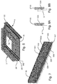
Figs 8A and 8B are end views, on a larger scale, of the detail ofFig. 7 cooperating with a lining panel in two different installation situations; -
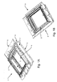
Figs 9A to 9B and10 are schematic perspective views of a window in a further embodiment of the invention; -
Fig. 9c is a cross-sectional fragmentary view along the line IX-IX inFig. 9A ; -
Fig. 11 is a schematic perspective view of an alternative window; -
Fig. 12A is a perspective view of an underfelt collar of the window ofFigs 9A-9B ,10 and 11 ; -
Fig. 12B is a perspective view of a prior art underfelt collar; -
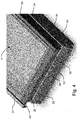
Fig. 13 is a perspective view of a flashing arrangement of a still further embodiment of the window according to the invention; -
Fig. 14 is an exploded perspective view of the flashing arrangement shown inFig. 13 ; -
Figs 15 and16 are further exploded perspective views of details the flashing arrangement ofFig. 14 ; and -
Figs 17 and 18 are perspective views, on a larger scale, of a detail of the flashing arrangement ofFig. 13 . - In
Figs 1A, 1B and2 , a window generally designated 1 is shown, in a position representing a mounted condition in an inclined roof with an undulated roofing material such as tiles represented by twotiles 10 inFig. 2 . The supporting roof construction is not shown but typically includes rafters, battens and counter-battens. - The window 1 comprises a
sash 2 hingedly connected to a frame generally designated 3. Thesash 2 carries apane 4. - The
frame 3 is adapted to cooperate with a set of transition assemblies to form a transition to the interior, to the roof construction and to the surrounding roofing, respectively. - According to the present invention, the transition towards the interior of the building below the window is provided in that the set of transition assemblies comprises a first transition assembly in the supply condition to form a climate-proofing transition between the window 1 and the roof construction in the mounted condition as illustrated by the embodiment shown in
Figs 1A-1B and2 . In the specific embodiments shown inFigs 9A-9C ,10 ,11 and12A , the second transition assembly comprises anunderfelt collar 7 connected to theframe 3 of the window 1 in the supply condition as will described in detail later. - Optionally, the first transition assembly also includes an
insulation element 6 as will also be described further below. - The window may also include a second transition assembly in the form of a
lining support arrangement 5 connected to theframe 3 and adapted to cooperate with a window lining including a set of lining panels 9 (cf.Figs 8A and 8B ) to be described in further detail below with particular reference toFigs 3 to 8B . - Eventually, a weather-tight transition between the window 1 and the surrounding
roofing 10 in the mounted condition is provided by means of a third transition assembly comprising aflashing arrangement 8. This will be described in further detail with particular reference toFigs 13 to 18 . - Turning now to
Figs 3 to 5 showing a window of one embodiment of the invention in a supply condition, the features of the window 1 will be described in some detail. - The
sash 2 is shown withsash members frame 3 is provided at the top of the window 1 and is constituted bysash hinge part 25a cooperating withframe hinge part 25b and interconnected byhinge pin 25c. - In the embodiments shown in the drawing, the
frame 3 is provided as a two-part frame including afirst sub-frame 3a adjacent thesash 2 and including fourfirst frame members second sub-frame 3b including foursecond frame members - To operate the window 1 and to position the
sash 2 in a ventilating position relative to theframe 3, anopening device 27 is provided. Theopening device 27 comprises a guidingconsole 28a, afirst tap 28b,pivot bushing 28c, and asecond tap 28d connected to thebottom frame member 32 of the first frame. Connectingmember 29a withlink 29b is viapivot bushing 28c connected to stayarm 29c. Stayarm 29c is provided with a series of apertures, here twoapertures 29d, to cooperate withfirst tap 28b orsecond tap 28d in a ventilating position. Thesash 2 is opened by handlingstay arm 29c, for instance by grippinghandle portion 28e, and lifting thestay arm 29c out of engagement withsecond tap 28d through right-hand aperture 29d, liftinglink 29b out of engagement withfirst tap 28b, swingingsash 2 outwards. A desired ventilating position is provided by re-positioning one ofapertures 29d overfirst tap 28b. - The
pane 4 is formed as a two-sheet stepped pane comprisingexterior pane sheet 41 andinterior pane sheet 42. In the embodiment shown,fittings 26 at thebottom sash member 22 are positioned in close proximity to the lower edge of theexterior pane sheet 41. - Other components not described in detail form part of the weathershield of the roof and include frame and sash claddings and covers, flashings, roofing felt, insulation and underroof, of which side frame covering 34a is shown.
- According to the present invention, bringing the window 1 from a supply condition to a mounted condition in a roof construction, for instance as indicated in
Fig. 2 , involves connecting theframe 3 of the window 1 to the roof structure. - Referring now to
Figs 9A-9C and10 , it is shown how the window is provided with a first transition assembly in the form of anunderfelt collar 7 to form a climate-proofing transition between the window and the roof construction. Theunderfelt collar 7 is provided with a frame engagement section in the form ofrim 71 fastened to theframe 3 and a roofstructure engagement section 72 extending from the frame engagement section. Theframe engagement section 71 may be attached by suitable means, for instance double-adhesive tape or staples. - In the embodiment shown in the drawing, the
frame engagement section 71 is attached to the first frame members 31-34 so that it covers and protects the joint between the first andsecond sub-frames - As is best seen in
Fig. 12A theunderfelt collar 7 in this embodiment is shaped with an exterior collar section adapted for being located at the first sub-frame and including theframe engagement section 71, a bridge collar section and an interior collar section adapted for extending over the second sub-frame in the supply condition and forming the main part of the roofstructure engagement section 72. Each of these sections is made from four pieces extending along the top, bottom and side frame members, respectively. The parts of the exterior collar section to be located at the bottom and side frame member are substantially straight, while the part to be located at the top frame member is curved and gradually extending away from the frame opening. All parts of the interior collar section become gradually wider width in a direction parallel to the corresponding frame member with the distance to the frame engagement section, but the interconnections between the top piece and the side pieces are more inclined than the interconnections between the bottom and side pieces. - In
Figs 9A, 9B ,10 and 11 the side pieces of the interior section of theunderfelt collar 7 are not connected to the top piece over their entire height. This allows the top piece to come down between thelining support members insulation element 6 provided at the top member of the frame as may best be seen inFigs 9A, 9B and10 , but may also be used for making room for other transition assemblies or parts thereof. - In
Fig. 12A the underfelt collar is shown as being made without a surplus of material, but it will be understood that particularly the roofstructure engagement section 72 may be provided with area increasing means such as for instance pleats or folds in a manner known per se and as indicated in the prior art collar 7' ofFig. 8B . It is also possible to make the collar from an elastic material. - As illustrated schematically in
Fig. 9c the roofstructure engagement section 72 may be folded in the supply condition so that the edge furthest from theframe engagement section 71 is arranged at the bridge section. Ones the window has been positioned in the roof structure, the roof structure engagement section can be unfolded to extend over the roof structure substantially in parallel with the plane of the roof and possibly attached thereto. - The edge of the roof
structure engagement section 72 may be attached to the exterior surface of the underfelt collar to keep it in place during transport, handling and installation, using for example an adhesive. - It will be understood that the folding of the underfelt collar may be embodied in many ways for example by bending it several times and that the edge furthest from the frame engagement section does not have to be arranged at the bridge section, but it should of course be possible to get a hold of it when the window has been positioned in the roof structure. Likewise it will be understood that a similar effect may be achieved by rolling the underfelt collar instead of folding it.
- In the embodiments shown in the drawing, the window further includes a second transition assembly in the form of
lining support arrangement 5 will be described in some detail. Thelining support arrangement 5 is connected to theframe 3 of the window 1 in its supply condition and supports the window lining 9 in the mounted condition, cf.Figs 8A and 8B . Thelining support arrangement 5 includes support means allowing variation of the angle between thewindow lining 9 and theframe 3. - In the one embodiment, the
lining support arrangement 5 comprises a number of longitudinally extendinglining support members frame 3 in the supply condition. The support means of thelining support arrangement 5 is provided by alining engagement portion 535 of each lining support member, here represented by liningsupport member 53, formed as longitudinal bead having a part-cylindrical cross-sectional shape. - In addition, the
lining support member 53 comprises a firstframe engaging face 531 forming a top surface, a secondframe engaging face 532 forming a side surface, aback side 533, a first steppedportion 534 extending between the secondframe engaging surface 532 and thelining engaging portion 535, and a second steppedportion 536 extending between the liningengagement portion 535 and abottom surface 537, the transverse dimension between the secondengaging face 532 and theback side 533 being larger than the transverse dimension between the first steppedportion 534 and theback side 533 and between the second steppedportion 536 and theback side 533. The second steppedportion 536 is here inclined such that the transverse dimension between the second steppedportion 536 and theback side 533 is larger at thelining engagement portion 535 than at thebottom surface 537. - In the two-part configuration of the
window frame 3 of the embodiment, thelining support arrangement 5 cooperates with the second frame 35-38. To that end, the second frame member, here shown assecond frame member 38, is provided with a rabbet 380 forming abottom face 381 and aside face 382 to abut the first and second frame engaging faces 531, 532, respectively, of the lining support members 51-54. - The lining support arrangement is the subject-matter of Applicant's co-pending patent application filed on the same date as the present application.
- In the alternative window shown in
Fig. 11 , nolining support arrangement 5 is present, just as noinsulation element 6 is present. - Eventually, the window is in the embodiment shown provided with a third transition assembly to form a weather-tight transition between the window and the roof construction in the mounted condition, comprising a flashing
assembly 8. - The window 1 according to the invention may be supplied with only the first transition assembly, viz. the
underfelt collar 7, and optionally with the second and/or third transition assemblies. - The flashing
assembly 8 is the subject-matter of Applicant's co-pending patent application filed on the same date as the present application. The contents thereof are incorporated by specific reference, and the flashingassembly 8 will not be described in further detail than the below listing of elements: - 81
- gutter element
811 middle piece
812 tile-supporting piece
813 deflector piece
814 left-hand gutter side piece
815 right-hand gutter side piece - 82
- skirt element
820 apron foam
821 apron piece
822 middle piece
823 left-hand skirt side piece
824 right-hand skirt side piece - 83
- left-hand water raiser
- 84
- right-hand water raiser
- 85
- left-hand connecting piece
- 86
- right-hand connecting piece
- 87
- screen element
871 first side edge
872 second side edge
873 bent portion
874 flange
875 dimples - The invention should not be regarded as being limited to the embodiments shown in the drawings and described in the above. Several modifications and combinations may be carried out within the scope of the appended claims. Particularly it is noted that the transition assemblies described above are in principle independent of each other and may therefore be use in any desired combination, but that slight adaptations may be needed for certain combinations. For example, the use of insulation elements may necessitate an adaptation of the shape of the underfelt collar and/or a flashing assembly.
Claims (10)
- A window (1) having a supply condition and a mounted condition in a roof construction of a building, comprising a frame (3) including a plurality of frame members defining a frame opening and a frame plane, said frame being adapted to cooperate with a set of transition assemblies in the mounted condition, and said frame having an interior side adapted to face the interior of the building in the mounted condition and an exterior side adapted to face the interior of the building in the mounted condition, the distance between the interior side and the exterior side defining a depth of the frame, and each frame member having an inner side facing the frame opening and an outer side facing away from the frame opening, characterized in that the distance between the outer sides of two opposite frame members varies over the depth of the frame, so that an outer dimension of the frame is larger at a first level at the interior side of the frame than at a second level closer to the exterior side of the frame, said first and second planes being substantially parallel with the frame plane, and in that the window is provided with a transition assembly to form a climate-proofing transition between the window and the roof construction in the mounted condition, said transition assembly comprising an underfelt collar (7) with a frame engagement section (71) and a roof structure engagement section (72), wherein the frame engagement section is connected to the frame (3) at the second level in the supply condition and wherein the width of at least one roof structure engagement section (72) in a direction parallel to the corresponding frame member increases gradually with the distance to the frame engagement section at least over a section of the roof structure engagement section.
- A window according to claim 1, wherein in the supply condition the underfelt collar (7) is in a folded or rolled-up state.
- A window according to any of the preceding claims, wherein the frame is substantially rectangular and including at least on top frame member (31; 35), at least one bottom frame member (32; 36) and at least two side frame members (33, 34; 37, 38).
- A window according to any of the preceding claims, wherein the frame (3) is a two-part frame including a first sub-frame (3a) carrying a sash (2) and a second sub-frame (3b) adapted for being connected to the roof construction, and wherein the underfelt collar (7) is connected to the second sub-frame.
- A window according to claim 3 or 4, wherein the second sub-frame (3b) is made from an insulating material, such as foamed polyurethan.
- A window according to any of the preceding claims, wherein the frame further comprises at least one additional transition assembly chosen from the group consisting of: insulation elements (6), mounting brackets for interconnecting the frame to the roof structure, a flashing assembly (8), a lining support arrangement (5) and a vapour barrier.
- A window according to claim 6 when dependent on claim 4, wherein the additional transition assembly/assemblies is/are provided on the second sub-frame (3b).
- A window according to claim 6 or 7, wherein an insulation element (6) is provided at the top member (31, 35) of the frame (3), said insulation element possibly being attached to the underfelt collar.
- A window according to claim 6, where a lining support arrangement (5) is connected to the frame (3) of the window (1) in its supply condition and adapted to support a window lining (9) in the mounted condition, where said lining support arrangement (5) includes support means allowing variation of the angle between the window lining (9) and the frame (3), and wherein the lining support arrangement (5) comprises a number of longitudinally extending lining support members (51-54) to form a frame-shaped structure connected to the frame (3) in the supply condition and the support means of the lining support arrangement (5) is provided by a lining engagement portion (535) of each lining support member (51-54), formed as longitudinal bead having a part-cylindrical cross-sectional shape.
- A window according to claim 6, wherein the window is provided with a transition assembly to form a weather-tight transition between the window and the roof construction in the mounted condition, comprising a flashing assembly (8).
Priority Applications (1)
| Application Number | Priority Date | Filing Date | Title |
|---|---|---|---|
| PL15203048T PL3061885T3 (en) | 2015-02-26 | 2015-12-30 | Window including a climate-shielding transition assembly |
Applications Claiming Priority (1)
| Application Number | Priority Date | Filing Date | Title |
|---|---|---|---|
| DKPA201570107A DK179674B1 (en) | 2015-02-26 | 2015-02-26 | Window including a climate-shielding transition assembly |
Publications (2)
| Publication Number | Publication Date |
|---|---|
| EP3061885A1 true EP3061885A1 (en) | 2016-08-31 |
| EP3061885B1 EP3061885B1 (en) | 2017-10-04 |
Family
ID=55027561
Family Applications (1)
| Application Number | Title | Priority Date | Filing Date |
|---|---|---|---|
| EP15203048.2A Active EP3061885B1 (en) | 2015-02-26 | 2015-12-30 | Window including a climate-shielding transition assembly |
Country Status (3)
| Country | Link |
|---|---|
| EP (1) | EP3061885B1 (en) |
| DK (1) | DK179674B1 (en) |
| PL (1) | PL3061885T3 (en) |
Cited By (1)
| Publication number | Priority date | Publication date | Assignee | Title |
|---|---|---|---|---|
| EP3670779A1 (en) * | 2018-12-19 | 2020-06-24 | VKR Holding A/S | A flashing element for a roof window and a method for making a flashing element |
Citations (8)
| Publication number | Priority date | Publication date | Assignee | Title |
|---|---|---|---|---|
| CH642421A5 (en) * | 1978-11-15 | 1984-04-13 | Frank Gmbh Wilh | Covering frame for a dormer window |
| DE9316695U1 (en) * | 1993-11-02 | 1994-02-24 | Büttner, Thomas, 72800 Eningen | Attachment frame for mounting roof windows on roof-insulated roofs (warm roof) |
| DE4304386A1 (en) * | 1993-02-13 | 1994-08-25 | Bauder Paul Gmbh & Co | Securing means for a dormer window |
| EP0615037A1 (en) * | 1993-03-06 | 1994-09-14 | Zura Fabrikations Ag | Building's roof |
| US20020095884A1 (en) * | 2001-01-19 | 2002-07-25 | Claes Lindgren | Roof window assembly and components |
| EP1510631A1 (en) * | 2003-08-30 | 2005-03-02 | Roto Frank Ag | Skylight |
| EP1925761A1 (en) * | 2003-12-30 | 2008-05-28 | VKR Holding A/S | Window and insulating frame kit |
| EP2253769A2 (en) * | 2009-05-15 | 2010-11-24 | Roto Frank Ag | Assembly of structural elements for a roof |
Family Cites Families (2)
| Publication number | Priority date | Publication date | Assignee | Title |
|---|---|---|---|---|
| GB1105712A (en) * | 1966-07-20 | 1968-03-13 | William J Cox Sales Ltd | Improvements in domed rooflights |
| DE3401738A1 (en) * | 1984-01-19 | 1985-07-25 | Heinz Essmann Gmbh & Co Kg, 4902 Bad Salzuflen | Ventilation apparatus, preferably for a flat roof |
-
2015
- 2015-02-26 DK DKPA201570107A patent/DK179674B1/en active IP Right Grant
- 2015-12-30 EP EP15203048.2A patent/EP3061885B1/en active Active
- 2015-12-30 PL PL15203048T patent/PL3061885T3/en unknown
Patent Citations (8)
| Publication number | Priority date | Publication date | Assignee | Title |
|---|---|---|---|---|
| CH642421A5 (en) * | 1978-11-15 | 1984-04-13 | Frank Gmbh Wilh | Covering frame for a dormer window |
| DE4304386A1 (en) * | 1993-02-13 | 1994-08-25 | Bauder Paul Gmbh & Co | Securing means for a dormer window |
| EP0615037A1 (en) * | 1993-03-06 | 1994-09-14 | Zura Fabrikations Ag | Building's roof |
| DE9316695U1 (en) * | 1993-11-02 | 1994-02-24 | Büttner, Thomas, 72800 Eningen | Attachment frame for mounting roof windows on roof-insulated roofs (warm roof) |
| US20020095884A1 (en) * | 2001-01-19 | 2002-07-25 | Claes Lindgren | Roof window assembly and components |
| EP1510631A1 (en) * | 2003-08-30 | 2005-03-02 | Roto Frank Ag | Skylight |
| EP1925761A1 (en) * | 2003-12-30 | 2008-05-28 | VKR Holding A/S | Window and insulating frame kit |
| EP2253769A2 (en) * | 2009-05-15 | 2010-11-24 | Roto Frank Ag | Assembly of structural elements for a roof |
Cited By (1)
| Publication number | Priority date | Publication date | Assignee | Title |
|---|---|---|---|---|
| EP3670779A1 (en) * | 2018-12-19 | 2020-06-24 | VKR Holding A/S | A flashing element for a roof window and a method for making a flashing element |
Also Published As
| Publication number | Publication date |
|---|---|
| DK201570107A1 (en) | 2016-09-12 |
| PL3061885T3 (en) | 2018-03-30 |
| DK179674B1 (en) | 2019-03-19 |
| EP3061885B1 (en) | 2017-10-04 |
Similar Documents
| Publication | Publication Date | Title |
|---|---|---|
| US6640508B2 (en) | Roof window assembly and components | |
| US20140331573A1 (en) | Rail mounting system for mounting skylights and the like directly to rib elevations of a raised rib metal panel roofing system | |
| US5924925A (en) | Roof ventilating system for frame construction building | |
| EP2472027B1 (en) | A method for mounting a flashing to a roof window | |
| US20040139669A1 (en) | Flashing component for a roof window assembly | |
| US9016008B2 (en) | Roofing cap system | |
| DK179519B1 (en) | A roof window installed in an inclined roof structure with a flashing assembly and a method for weather proofing a roof window | |
| EP3480388B1 (en) | A flashing member for a roof element, such as a roof window, and a flashing kit | |
| US6848220B2 (en) | Flashing | |
| US20120011787A1 (en) | Deck-sealing surround for skylights and windows | |
| CZ20002279A3 (en) | Insulation frame | |
| EP2472029B1 (en) | A method for mounting a flashing for a roof window and a flashing system for a roof window | |
| WO2020071932A1 (en) | Roof window frame with installation set and flashing assembly | |
| EP1706557B1 (en) | Window and insulating frame kit | |
| EP2472025B1 (en) | A flashing member with a compensation member and a kit including such a flashing member | |
| US9528272B2 (en) | Roofing cap system | |
| EP2487307A2 (en) | Window set for barrel roof | |
| SK42498A3 (en) | A sheet metal flashing member for frame structures of roof windows or similar roof penetrating building structures and a flashing frame comprising such a member | |
| EP3061885B1 (en) | Window including a climate-shielding transition assembly | |
| EP3599321B1 (en) | Kit of parts and method of flashing a roof element | |
| EP2185776B1 (en) | Roof window | |
| EP3061884B1 (en) | Window including a support arrangement for a window lining | |
| EP3061886B1 (en) | Flashing arrangement for a window, window with a flashing arrangement, and method of providing a weather-tight transition between a window and surrounding roofing with such a flashing arrangement | |
| RU194971U1 (en) | MANSARD WINDOW | |
| EP1111152A2 (en) | Panel support bar |
Legal Events
| Date | Code | Title | Description |
|---|---|---|---|
| PUAI | Public reference made under article 153(3) epc to a published international application that has entered the european phase |
Free format text: ORIGINAL CODE: 0009012 |
|
| AK | Designated contracting states |
Kind code of ref document: A1 Designated state(s): AL AT BE BG CH CY CZ DE DK EE ES FI FR GB GR HR HU IE IS IT LI LT LU LV MC MK MT NL NO PL PT RO RS SE SI SK SM TR |
|
| AX | Request for extension of the european patent |
Extension state: BA ME |
|
| 17P | Request for examination filed |
Effective date: 20170224 |
|
| RBV | Designated contracting states (corrected) |
Designated state(s): AL AT BE BG CH CY CZ DE DK EE ES FI FR GB GR HR HU IE IS IT LI LT LU LV MC MK MT NL NO PL PT RO RS SE SI SK SM TR |
|
| GRAP | Despatch of communication of intention to grant a patent |
Free format text: ORIGINAL CODE: EPIDOSNIGR1 |
|
| RIC1 | Information provided on ipc code assigned before grant |
Ipc: E04D 13/147 20060101ALN20170327BHEP Ipc: E04D 13/03 20060101AFI20170327BHEP |
|
| INTG | Intention to grant announced |
Effective date: 20170419 |
|
| GRAS | Grant fee paid |
Free format text: ORIGINAL CODE: EPIDOSNIGR3 |
|
| GRAA | (expected) grant |
Free format text: ORIGINAL CODE: 0009210 |
|
| AK | Designated contracting states |
Kind code of ref document: B1 Designated state(s): AL AT BE BG CH CY CZ DE DK EE ES FI FR GB GR HR HU IE IS IT LI LT LU LV MC MK MT NL NO PL PT RO RS SE SI SK SM TR |
|
| REG | Reference to a national code |
Ref country code: GB Ref legal event code: FG4D |
|
| REG | Reference to a national code |
Ref country code: CH Ref legal event code: EP |
|
| REG | Reference to a national code |
Ref country code: AT Ref legal event code: REF Ref document number: 934199 Country of ref document: AT Kind code of ref document: T Effective date: 20171015 |
|
| REG | Reference to a national code |
Ref country code: IE Ref legal event code: FG4D |
|
| REG | Reference to a national code |
Ref country code: DE Ref legal event code: R096 Ref document number: 602015005179 Country of ref document: DE |
|
| REG | Reference to a national code |
Ref country code: FR Ref legal event code: PLFP Year of fee payment: 3 |
|
| REG | Reference to a national code |
Ref country code: NL Ref legal event code: MP Effective date: 20171004 |
|
| REG | Reference to a national code |
Ref country code: LT Ref legal event code: MG4D |
|
| REG | Reference to a national code |
Ref country code: AT Ref legal event code: MK05 Ref document number: 934199 Country of ref document: AT Kind code of ref document: T Effective date: 20171004 |
|
| PG25 | Lapsed in a contracting state [announced via postgrant information from national office to epo] |
Ref country code: NL Free format text: LAPSE BECAUSE OF FAILURE TO SUBMIT A TRANSLATION OF THE DESCRIPTION OR TO PAY THE FEE WITHIN THE PRESCRIBED TIME-LIMIT Effective date: 20171004 |
|
| PG25 | Lapsed in a contracting state [announced via postgrant information from national office to epo] |
Ref country code: LT Free format text: LAPSE BECAUSE OF FAILURE TO SUBMIT A TRANSLATION OF THE DESCRIPTION OR TO PAY THE FEE WITHIN THE PRESCRIBED TIME-LIMIT Effective date: 20171004 Ref country code: ES Free format text: LAPSE BECAUSE OF FAILURE TO SUBMIT A TRANSLATION OF THE DESCRIPTION OR TO PAY THE FEE WITHIN THE PRESCRIBED TIME-LIMIT Effective date: 20171004 Ref country code: FI Free format text: LAPSE BECAUSE OF FAILURE TO SUBMIT A TRANSLATION OF THE DESCRIPTION OR TO PAY THE FEE WITHIN THE PRESCRIBED TIME-LIMIT Effective date: 20171004 Ref country code: SE Free format text: LAPSE BECAUSE OF FAILURE TO SUBMIT A TRANSLATION OF THE DESCRIPTION OR TO PAY THE FEE WITHIN THE PRESCRIBED TIME-LIMIT Effective date: 20171004 Ref country code: NO Free format text: LAPSE BECAUSE OF FAILURE TO SUBMIT A TRANSLATION OF THE DESCRIPTION OR TO PAY THE FEE WITHIN THE PRESCRIBED TIME-LIMIT Effective date: 20180104 |
|
| PG25 | Lapsed in a contracting state [announced via postgrant information from national office to epo] |
Ref country code: GR Free format text: LAPSE BECAUSE OF FAILURE TO SUBMIT A TRANSLATION OF THE DESCRIPTION OR TO PAY THE FEE WITHIN THE PRESCRIBED TIME-LIMIT Effective date: 20180105 Ref country code: RS Free format text: LAPSE BECAUSE OF FAILURE TO SUBMIT A TRANSLATION OF THE DESCRIPTION OR TO PAY THE FEE WITHIN THE PRESCRIBED TIME-LIMIT Effective date: 20171004 Ref country code: AT Free format text: LAPSE BECAUSE OF FAILURE TO SUBMIT A TRANSLATION OF THE DESCRIPTION OR TO PAY THE FEE WITHIN THE PRESCRIBED TIME-LIMIT Effective date: 20171004 Ref country code: LV Free format text: LAPSE BECAUSE OF FAILURE TO SUBMIT A TRANSLATION OF THE DESCRIPTION OR TO PAY THE FEE WITHIN THE PRESCRIBED TIME-LIMIT Effective date: 20171004 Ref country code: IS Free format text: LAPSE BECAUSE OF FAILURE TO SUBMIT A TRANSLATION OF THE DESCRIPTION OR TO PAY THE FEE WITHIN THE PRESCRIBED TIME-LIMIT Effective date: 20180204 Ref country code: BG Free format text: LAPSE BECAUSE OF FAILURE TO SUBMIT A TRANSLATION OF THE DESCRIPTION OR TO PAY THE FEE WITHIN THE PRESCRIBED TIME-LIMIT Effective date: 20180104 Ref country code: HR Free format text: LAPSE BECAUSE OF FAILURE TO SUBMIT A TRANSLATION OF THE DESCRIPTION OR TO PAY THE FEE WITHIN THE PRESCRIBED TIME-LIMIT Effective date: 20171004 |
|
| REG | Reference to a national code |
Ref country code: DE Ref legal event code: R097 Ref document number: 602015005179 Country of ref document: DE |
|
| PG25 | Lapsed in a contracting state [announced via postgrant information from national office to epo] |
Ref country code: CZ Free format text: LAPSE BECAUSE OF FAILURE TO SUBMIT A TRANSLATION OF THE DESCRIPTION OR TO PAY THE FEE WITHIN THE PRESCRIBED TIME-LIMIT Effective date: 20171004 Ref country code: EE Free format text: LAPSE BECAUSE OF FAILURE TO SUBMIT A TRANSLATION OF THE DESCRIPTION OR TO PAY THE FEE WITHIN THE PRESCRIBED TIME-LIMIT Effective date: 20171004 Ref country code: DK Free format text: LAPSE BECAUSE OF FAILURE TO SUBMIT A TRANSLATION OF THE DESCRIPTION OR TO PAY THE FEE WITHIN THE PRESCRIBED TIME-LIMIT Effective date: 20171004 Ref country code: SK Free format text: LAPSE BECAUSE OF FAILURE TO SUBMIT A TRANSLATION OF THE DESCRIPTION OR TO PAY THE FEE WITHIN THE PRESCRIBED TIME-LIMIT Effective date: 20171004 |
|
| PLBE | No opposition filed within time limit |
Free format text: ORIGINAL CODE: 0009261 |
|
| STAA | Information on the status of an ep patent application or granted ep patent |
Free format text: STATUS: NO OPPOSITION FILED WITHIN TIME LIMIT |
|
| PG25 | Lapsed in a contracting state [announced via postgrant information from national office to epo] |
Ref country code: IT Free format text: LAPSE BECAUSE OF FAILURE TO SUBMIT A TRANSLATION OF THE DESCRIPTION OR TO PAY THE FEE WITHIN THE PRESCRIBED TIME-LIMIT Effective date: 20171004 Ref country code: RO Free format text: LAPSE BECAUSE OF FAILURE TO SUBMIT A TRANSLATION OF THE DESCRIPTION OR TO PAY THE FEE WITHIN THE PRESCRIBED TIME-LIMIT Effective date: 20171004 Ref country code: SM Free format text: LAPSE BECAUSE OF FAILURE TO SUBMIT A TRANSLATION OF THE DESCRIPTION OR TO PAY THE FEE WITHIN THE PRESCRIBED TIME-LIMIT Effective date: 20171004 |
|
| 26N | No opposition filed |
Effective date: 20180705 |
|
| PG25 | Lapsed in a contracting state [announced via postgrant information from national office to epo] |
Ref country code: MT Free format text: LAPSE BECAUSE OF NON-PAYMENT OF DUE FEES Effective date: 20171230 Ref country code: LU Free format text: LAPSE BECAUSE OF NON-PAYMENT OF DUE FEES Effective date: 20171230 |
|
| REG | Reference to a national code |
Ref country code: IE Ref legal event code: MM4A |
|
| REG | Reference to a national code |
Ref country code: BE Ref legal event code: MM Effective date: 20171231 |
|
| PG25 | Lapsed in a contracting state [announced via postgrant information from national office to epo] |
Ref country code: IE Free format text: LAPSE BECAUSE OF NON-PAYMENT OF DUE FEES Effective date: 20171230 |
|
| PG25 | Lapsed in a contracting state [announced via postgrant information from national office to epo] |
Ref country code: BE Free format text: LAPSE BECAUSE OF NON-PAYMENT OF DUE FEES Effective date: 20171231 Ref country code: SI Free format text: LAPSE BECAUSE OF FAILURE TO SUBMIT A TRANSLATION OF THE DESCRIPTION OR TO PAY THE FEE WITHIN THE PRESCRIBED TIME-LIMIT Effective date: 20171004 |
|
| PG25 | Lapsed in a contracting state [announced via postgrant information from national office to epo] |
Ref country code: MC Free format text: LAPSE BECAUSE OF FAILURE TO SUBMIT A TRANSLATION OF THE DESCRIPTION OR TO PAY THE FEE WITHIN THE PRESCRIBED TIME-LIMIT Effective date: 20171004 Ref country code: HU Free format text: LAPSE BECAUSE OF FAILURE TO SUBMIT A TRANSLATION OF THE DESCRIPTION OR TO PAY THE FEE WITHIN THE PRESCRIBED TIME-LIMIT; INVALID AB INITIO Effective date: 20151230 |
|
| REG | Reference to a national code |
Ref country code: CH Ref legal event code: PL |
|
| PG25 | Lapsed in a contracting state [announced via postgrant information from national office to epo] |
Ref country code: CY Free format text: LAPSE BECAUSE OF FAILURE TO SUBMIT A TRANSLATION OF THE DESCRIPTION OR TO PAY THE FEE WITHIN THE PRESCRIBED TIME-LIMIT Effective date: 20171004 |
|
| PG25 | Lapsed in a contracting state [announced via postgrant information from national office to epo] |
Ref country code: MK Free format text: LAPSE BECAUSE OF FAILURE TO SUBMIT A TRANSLATION OF THE DESCRIPTION OR TO PAY THE FEE WITHIN THE PRESCRIBED TIME-LIMIT Effective date: 20171004 |
|
| PG25 | Lapsed in a contracting state [announced via postgrant information from national office to epo] |
Ref country code: CH Free format text: LAPSE BECAUSE OF NON-PAYMENT OF DUE FEES Effective date: 20181231 Ref country code: LI Free format text: LAPSE BECAUSE OF NON-PAYMENT OF DUE FEES Effective date: 20181231 |
|
| PG25 | Lapsed in a contracting state [announced via postgrant information from national office to epo] |
Ref country code: TR Free format text: LAPSE BECAUSE OF FAILURE TO SUBMIT A TRANSLATION OF THE DESCRIPTION OR TO PAY THE FEE WITHIN THE PRESCRIBED TIME-LIMIT Effective date: 20171004 |
|
| PG25 | Lapsed in a contracting state [announced via postgrant information from national office to epo] |
Ref country code: PT Free format text: LAPSE BECAUSE OF FAILURE TO SUBMIT A TRANSLATION OF THE DESCRIPTION OR TO PAY THE FEE WITHIN THE PRESCRIBED TIME-LIMIT Effective date: 20171004 |
|
| PG25 | Lapsed in a contracting state [announced via postgrant information from national office to epo] |
Ref country code: AL Free format text: LAPSE BECAUSE OF FAILURE TO SUBMIT A TRANSLATION OF THE DESCRIPTION OR TO PAY THE FEE WITHIN THE PRESCRIBED TIME-LIMIT Effective date: 20171004 |
|
| PGFP | Annual fee paid to national office [announced via postgrant information from national office to epo] |
Ref country code: GB Payment date: 20241107 Year of fee payment: 10 |
|
| PGFP | Annual fee paid to national office [announced via postgrant information from national office to epo] |
Ref country code: FR Payment date: 20241121 Year of fee payment: 10 |
|
| PGFP | Annual fee paid to national office [announced via postgrant information from national office to epo] |
Ref country code: DE Payment date: 20251104 Year of fee payment: 11 |
|
| PGFP | Annual fee paid to national office [announced via postgrant information from national office to epo] |
Ref country code: PL Payment date: 20251117 Year of fee payment: 11 |