EP3061878B1 - Sammelvorrichtung für oberflächenwasser - Google Patents
Sammelvorrichtung für oberflächenwasser Download PDFInfo
- Publication number
- EP3061878B1 EP3061878B1 EP16157441.3A EP16157441A EP3061878B1 EP 3061878 B1 EP3061878 B1 EP 3061878B1 EP 16157441 A EP16157441 A EP 16157441A EP 3061878 B1 EP3061878 B1 EP 3061878B1
- Authority
- EP
- European Patent Office
- Prior art keywords
- collecting
- module
- duct
- collection
- removable strip
- Prior art date
- Legal status (The legal status is an assumption and is not a legal conclusion. Google has not performed a legal analysis and makes no representation as to the accuracy of the status listed.)
- Active
Links
- XLYOFNOQVPJJNP-UHFFFAOYSA-N water Substances O XLYOFNOQVPJJNP-UHFFFAOYSA-N 0.000 title claims description 24
- 238000007689 inspection Methods 0.000 claims description 13
- 238000007599 discharging Methods 0.000 claims description 9
- 238000009434 installation Methods 0.000 description 8
- 239000002689 soil Substances 0.000 description 6
- 239000011248 coating agent Substances 0.000 description 5
- 238000000576 coating method Methods 0.000 description 5
- 239000004567 concrete Substances 0.000 description 5
- 230000006866 deterioration Effects 0.000 description 3
- 239000007788 liquid Substances 0.000 description 3
- 239000000463 material Substances 0.000 description 3
- 230000000717 retained effect Effects 0.000 description 3
- 230000009182 swimming Effects 0.000 description 3
- XECAHXYUAAWDEL-UHFFFAOYSA-N acrylonitrile butadiene styrene Chemical compound C=CC=C.C=CC#N.C=CC1=CC=CC=C1 XECAHXYUAAWDEL-UHFFFAOYSA-N 0.000 description 2
- 229920000122 acrylonitrile butadiene styrene Polymers 0.000 description 2
- 239000004676 acrylonitrile butadiene styrene Substances 0.000 description 2
- 230000000694 effects Effects 0.000 description 2
- 238000009408 flooring Methods 0.000 description 2
- 230000014759 maintenance of location Effects 0.000 description 2
- 210000002445 nipple Anatomy 0.000 description 2
- ZAMOUSCENKQFHK-UHFFFAOYSA-N Chlorine atom Chemical compound [Cl] ZAMOUSCENKQFHK-UHFFFAOYSA-N 0.000 description 1
- 241000282341 Mustela putorius furo Species 0.000 description 1
- 238000009825 accumulation Methods 0.000 description 1
- 230000000844 anti-bacterial effect Effects 0.000 description 1
- 230000033228 biological regulation Effects 0.000 description 1
- 238000005266 casting Methods 0.000 description 1
- 229910052801 chlorine Inorganic materials 0.000 description 1
- 239000000460 chlorine Substances 0.000 description 1
- 239000003086 colorant Substances 0.000 description 1
- 239000003599 detergent Substances 0.000 description 1
- 238000001125 extrusion Methods 0.000 description 1
- 238000003780 insertion Methods 0.000 description 1
- 230000037431 insertion Effects 0.000 description 1
- 238000004519 manufacturing process Methods 0.000 description 1
- 238000012986 modification Methods 0.000 description 1
- 230000004048 modification Effects 0.000 description 1
- 239000004570 mortar (masonry) Substances 0.000 description 1
- 238000000465 moulding Methods 0.000 description 1
- 230000002093 peripheral effect Effects 0.000 description 1
- 239000011150 reinforced concrete Substances 0.000 description 1
- 230000003014 reinforcing effect Effects 0.000 description 1
- 230000006641 stabilisation Effects 0.000 description 1
- 238000011105 stabilization Methods 0.000 description 1
- 239000000126 substance Substances 0.000 description 1
- 229920002994 synthetic fiber Polymers 0.000 description 1
- 238000011144 upstream manufacturing Methods 0.000 description 1
- 239000003643 water by type Substances 0.000 description 1
Images

Classifications
-
- E—FIXED CONSTRUCTIONS
- E03—WATER SUPPLY; SEWERAGE
- E03F—SEWERS; CESSPOOLS
- E03F3/00—Sewer pipe-line systems
- E03F3/04—Pipes or fittings specially adapted to sewers
- E03F3/046—Open sewage channels
-
- E—FIXED CONSTRUCTIONS
- E03—WATER SUPPLY; SEWERAGE
- E03F—SEWERS; CESSPOOLS
- E03F5/00—Sewerage structures
- E03F5/04—Gullies inlets, road sinks, floor drains with or without odour seals or sediment traps
- E03F5/06—Gully gratings
- E03F2005/065—Gully gratings with elastic locking elements
Definitions
- the present invention relates to the field of collecting and discharging runoff.
- the present invention can mainly be used in wet rooms inside a building, especially bathrooms or showers, or collective kitchens, private or public pools and their ancillary premises.
- the present invention may also be used outside the building, especially at a terrace or an outdoor pool.
- the invention more particularly relates to a collection device comprising at least two elements, the first of these elements consisting of a gutter or collection conduit and the second element being a removable strip adapted to snap onto said collection conduit.
- the device allows, particularly advantageously, to facilitate the installation of the cover elements, for example tile or slabs, intended to come dressed the floor in which the device is installed.
- These devices generally comprise a liquid discharge pipe of substantially cylindrical or U-shaped section installed at a floor, said pipe communicating with the ground surface by means of a groove which extends along the pipe. Such a groove allows the passage of water to be discharged from the ground surface to the inside of the drain pipe buried deep in said floor.
- the throat is traditionally closed superiorly by means of a grid that can allow, in particular, a retention of objects having a large size.
- the document US 4,815,888 describes a water drainage pipe, in pools, topped with a grid that can be removed if necessary.
- the pipe is formed of a U-shaped hollow section with side walls on each side.
- the grid has a curved skirt on each lateral side for insertion into a space between flanges positioned at the distal ends of the side walls.
- the document DE 20 2009 003 283 U1 discloses a collection device having the features of the preamble of claim 1.
- such devices may be fragile and the grids covering the gutters or drain pipe of the state of the art have a number of disadvantages . Indeed, these grids are likely to be poorly positioned, and can, therefore, generate accidents. In addition, the grids can be stolen.
- a drainage and drainage drainage gutter comprising a cylindrical pipe equipped, at its upper part, with a rib flush with the surface of the finished floor, the latter being able in particular to be composed of a plurality of tiles.
- This rib has a plurality of slots allowing the passage of water to be discharged to the cylindrical tube of the gutter.
- This gutter is interesting because it allows to meet a number of issues that arise in the state of the art.
- said channel has, because of its size, good adaptability to any type of soil and avoids the presence of grids covering the channel, said grids being likely to cause accidents in case of misplacement.
- the upper rib is likely to be deteriorated due in particular to external factors, for example the use of chemicals in more or less large quantities, such as chlorine in buildings where swimming pools are located or detergent products in collective kitchens.
- Another disadvantage of the existing device lies in the fact that it can be unsightly. Indeed, the raceway being monobloc, the rib can only be the same color as the rest of the product. However, the soil intended to be equipped with said gutter may be of different colors, and the presence of the rib between two tile tiles may be particularly unsightly.
- the rib has a fixed height, regardless of the thickness of the flooring. It is then necessary to take precautions upstream of the laying of the floor covering, at the time of pouring the screed, so that the outer surface of said coating is flush or slightly above the upper rib. Such an operation can be restrictive.
- no element is provided to facilitate, on the one hand, the definition of the height at which the screed is to be poured and, on the other hand, the placement of the floor covering once the device is positioned in the concrete screed.
- the invention offers the possibility of overcoming the various drawbacks of the state of the art by proposing a device for collecting runoff water comprising at least one water collection pipe, intended to be sealed under the surface of a soil intended to to be covered with cover elements, said collection duct having a wall having an inner surface and an outer surface, and comprising an access opening to the surface of said floor.
- Said collection device comprises, on either side of said access, and extending projecting along at least a portion of the collection conduit, at least one retaining means of at least one removable strip, the latter having an inverted U-shaped general section with a transverse portion comprising at least one longitudinal slot to the device and bordered, on either side, by two branches, said removable strip having a height adapted to the thickness e of the covering elements and said at least one longitudinal slot constituting access to the interior of the collection duct.
- the cross section of the collection duct is a portion of a circle or a semicircle, defining, on either side of the access, two substantially flat support surfaces for laying the covering elements.
- said retaining means of said removable strip consists of a latching means, the end portions of the U-branches of said strip being shaped so that it snaps.
- said latching means comprises two tabs and two longitudinal ribs projecting on either side of said access, said two tabs being able to move elastically apart to receive said removable strip, the surfaces between each leg and each rib constituting each a fulcrum for the end parts of the branches of the U of the removable strip.
- the present device comprises two lateral fins disposed on either side of the collection duct and extending along at least a portion of said collection duct, each of said fins being issued substantially perpendicularly and substantially at mid-point. height on one side of the outer surface of the wall of said collection duct.
- the invention also relates to a module for collecting runoff water and a facility for collecting and discharging runoff water.
- the present invention relates to a collection device 1 for recovering runoff water from a room or a wet room of a building, for example a bathroom or a bathroom, a kitchen, including a collective kitchen, of a private or public indoor or outdoor swimming pool and adjacent rooms of said swimming pool, or of a terrace.
- Said collection duct 2 is intended to be sealed under the surface 3 of a floor 4, the latter consisting in particular of a yoke.
- the surface 3 of said floor 4 is then intended to be coated with cover elements 51, 52, the latter preferably consisting of, but not limited to, tile tiles.
- the covering elements 51, 52 may also consist, for example, of water-resistant parquet strips, of a waxed concrete layer, or of any other coating adapted to damp locations, inside. or outside a building.
- the cross section of the collection duct is in a semicircle.
- Such a cross section, in a portion of a circle or in a semicircle makes it possible to define, on either side of the access 6, and on either side of a retaining means 7 which will be described later, two support surfaces 91, 92 which are substantially planar, or planar, and which facilitate the installation of cover elements 51,52. Indeed, these support surfaces 91, 92 are found, during the casting of the yoke, substantially at the same level as that of the surface 3 of the ground 4, as shown in FIG. figure 1 .
- these support surfaces 91, 92 also facilitates the determination of the level where the screed must be cast, to facilitate the subsequent laying of the tile tiles 51, 52 in particular.
- the collecting duct 2 of the device 1 comprises a wall having an inner surface 21 and an outer surface 22, said inner surface 21 delimiting the inside 23 of said duct 2.
- the latter is advantageously provided with a plurality of ridges 24 intended to stabilize the collection duct 2 when it is placed at the level of the floor 4.
- the last may for example consist of a screed.
- said duct 2 further comprises two lateral fins 11, 12. These fins 11, 12 are disposed on either side of the collection duct 2, and extend along at least a portion thereof, and preferably over the entire length of said duct 2.
- Each of said fins 11,12 is issued, substantially perpendicularly and substantially at mid-height, on one side of the outer surface 22 of the collection duct 2.
- the lateral fins 11,12 have a generally parallelepiped shape.
- the presence of such fins 11, 12 allows, in association with the grooves 24 formed on the outer surface 22 of the wall of the collection conduit 2, to promote the setting and immobilization in position of said conduit 2 in the floor 4, avoiding any risk of rotation of said duct 2 about its longitudinal axis.
- the collecting duct 2 advantageously comprises an opening defining an access 6 opening on one side to the surface 3 of the floor 4 and, on the other side, to the inside 23 of the collection duct 2.
- the collection device 1 comprises, on either side of this access 6, and extending projecting along at least a portion of the collection duct 2, at least one retaining means 7 allowing the positioning in said duct 2 of at least one removable strip 8.
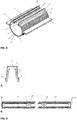
- the removable strip 8 forming part of the collection device 1 has a general shape of inverted U.
- a transverse portion 81 which comprises at least one longitudinal slot 82, visible on the Figure 4B and also represented on the figure 5 said slot 82 being longitudinal with respect to the collection device 1.
- the removable strip 8 may comprise a plurality of longitudinal slots 82 arranged one after the other, and between which are formed zones of materials preferably comprising reinforcing ribs 85, and this for the purpose of to give said strip 8 sufficient mechanical strength.
- the longitudinal slots 82 have a width of not more than 8 millimeters, so as to comply with the regulations in force.
- the width of the transverse portion 81 of the removable strip 8 does not exceed, preferably, 15 millimeters.
- the removable strip 8 inverted U comprises, on either side of this portion 81, two branches 83, 84.
- Said strip 8 advantageously has a height adapted to the thickness e of the covering elements 51, 52 of the surface 3 of the ground 4, so as to be flush with or just below the outer face of said elements 51, 52 to facilitate the passage of runoff into the interior 23 of the collection duct 2.
- the upper face of the strip 8 corresponding to the transverse portion 81, does not exceed the outer face 510, 520 of the cover elements 51 , 52.
- the removable strip 8 comprises, at one of its ends, a recentering stud 86 and, at the opposite end, a recentering groove 87.
- the collection device 1 according to the invention and in particular the presence of at least one removable strip 8, is particularly advantageous.
- the collection device 1 comprises a plurality of removable strips 8
- the removable strip 8 is held on the collection duct 2 by means of at least one retaining means 7.
- this retaining means 7 consists of a latching means 70, and the end portions 830,840 of the legs 83,84 of the U of the removable strip 8 are shaped so that it snaps.
- the end parts 830, 840 of the branches 83, 84 of the removable strip 8 are able to move apart elastically and come, from the outside, to tighten the snap-fastening means. 70.
- the latching means 70 comprises, on the one hand, two tabs 71, 72 which are able to elastically deviate to receive the removable strip 8 between said two tabs 71, 72.
- said means of latching 70 comprises two longitudinal ribs 710, 720, which protrude on either side of the access 6, along at least part of the collection duct 2.
- Between said tabs 71, 72 and said ribs 710, 720 are defined two surfaces 711, 721 respectively, preferably substantially planar, each of said surfaces 711, 721 constituting a fulcrum, or a housing, for end portions 830,840 83,84 branches of the inverted U of the removable strip 8.
- the said end portions 830,840 advantageously comprise a shoulder to match the shape of the tabs 71,72 for optimum retention of the strip 8 in position.
- Said detent means 70 may receive one or more removable strips 8.
- a plurality of removable strips 8 are abutted in the upper part of a collection duct 2.
- the advantage of this embodiment lies in the fact that it is possible to replace only one removable strip 8 in case of deterioration thereof, while leaving the strips 8 in operating state in position on the
- the collection device 1, in particular the duct 2 is sealed in the floor 4 of a damp room, inside or outside a building.
- the floor 4 is for example a finishing screed that can cover other elements not shown in the figure, including a seal, itself can be above at least one layer of reinforced concrete.
- the surface 3 of the floor 4 reaches substantially the same level as the support surfaces 91, 92. It is then easy to install the covering elements 51,52, for example tile tiles, on either side of the access 6 of the duct 2 covered by the removable strip 8.
- said removable strip 8 of the collection device 1 can be easily inserted between two rows of cover elements 51,52, especially between two adjacent rows of tiles.
- the removable strip 8, as well as the retaining means 7, are positioned in the space conventionally provided for making mortar joints between the tiles 51, 52 and / or the expansion joints.
- the removable strips 8 of the device 1 are provided in a color identical to that of the joints made at the rows of tiles between which said device 1 is not inserted.
- the (the) strip (s) removable (s) 8 of the collection device 1 incorporates (s) waterproof lighting, not shown, preferably light emitting diodes. These lights can be set up in the material areas between two longitudinal slots 82 at the upper face of the removable strip 8, always in order to improve the aesthetic effect of the device 1 according to the invention.
- the collection conduit 2 of the device according to the invention is monobloc and made of synthetic material, for example ABS (acrylonitrile butadiene styrene) extruded.
- ABS acrylonitrile butadiene styrene
- the removable strip 8 it is preferentially obtained by molding, which makes it possible to avoid any subsequent action on this element, in particular for piercing the longitudinal slots 82.
- the material used to make the collection conduit 2 receives an antibacterial treatment in full mass. It can advantageously be the same for the removable strip 8 of the device 1.
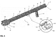
- the present invention also relates to a module 20 for collecting runoff water.
- Said connecting means 13 is able to connect, coaxially, the collection module 20 to a second identical module 20 and / or to a inspection hatch 15 and / or to a collection and evacuation module 21.
- a collection module 20 according to the invention may optionally incorporate two connection means 13, one at each end of said collection duct 2.
- connection means 13 An enlargement of one embodiment of a connection means 13 is shown on the figure 5 .
- said connecting means 13 is preferably composed of two open portions 130, 131 and an inner peripheral rib 134 having the same thickness as that of the wall of the collection duct 2, to ensure the centering and continuity between two collection ducts 2 of two modules 20 butted.
- a first portion 130 of the connecting means 13 cooperates by interlocking with the collection device 1 of a first module 20, the second portion 131 being able to cooperate, for example, with the device of collection 1 of a second module, in particular a module 21 as illustrated on the figure 5 .
- connection means 13 further comprises a central element 132 projecting and allowing centering perfect removable strips 8 positioned on either side of said element 132.
- said central element 132 comprises, on the one hand, a refocusing nipple 132a adapted to cooperate with the recentering groove 87 of a removable ruler 8 and, on the other hand, a refocusing groove 132b accommodating the nipple recentering 86 of a second removable strip 8.
- the connecting means 13 is advantageously retained at the lateral fins 11, 12 of the collection duct 2 by a clamping system, in particular by means of a plurality of gadroons 133.
- the collection and evacuation module 21 comprises, in addition to the elements of the collection module 20, at least one flow chute 16, communicating with the conduit 2 of said module 21, and allowing the evacuation, to the sewers, of the runoff water collected in said conduit 2.
- said collection and evacuation module 21 comprises, at its end opposite to that connected to the module 20, a closure means 17 of the duct 2.
- the invention also relates to a facility 100 for collecting and discharging runoff waters having, coaxially abutting, at least one collection module 20 and a collection and evacuation module 21 as described above.
- Said inspection hatch 15 is composed, preferably, of a hatch body 151 covered with a lid 152. These two elements of the inspection hatch 15 are advantageously secured by means of at least one fastening means, in particular a screw .
- the inspection flap 15 further comprises at least one connecting element of said flap 15 to a collection module 20 by interlocking.
- said hatch 15 already has, at each of its ends, a connecting element 153, 154.
- first connection element 153 allows the inspection flap 15 to be fitted to a collection module 20, whereas the second connection element 154, at the opposite end, can be used to fit said flap 15, for example to a second collection module, not shown on the figure 5 .
- the inspection hatch 15 it is also conceivable for the inspection hatch 15 to be positioned between a collection module 20 and a collection and evacuation module 21.
- said inspection hatch 15, comprising at each of its end a connecting element 153, 154, may constitute the connecting means of the collection module 20 according to the invention.
- the elements 153, 154 for connecting the flap 15 are preferably retained by the fins 11, 12 of the collection duct 2 by a clamping system, in particular by means of a plurality of gadroons 133.
- the collection and evacuation installation 100 comprises a collection module 20 which is connected at one of its ends to a inspection hatch 15 via a connecting element 153 which is located at At the other of its ends, said module 20 is abutted, via its connecting means 13, to a collection and evacuation module 21, which comprises a flow chute 16, communicating with the leads 2, and allowing evacuation to the sewers of the runoff water collected in the said conduit 2.
- the collection and evacuation module 21 comprises, at the end of its conduit 2 opposite to that connected to the module 20, a closure means 17 of said conduit 2, such as a plug.
Landscapes
- Health & Medical Sciences (AREA)
- Life Sciences & Earth Sciences (AREA)
- Engineering & Computer Science (AREA)
- Hydrology & Water Resources (AREA)
- Public Health (AREA)
- Water Supply & Treatment (AREA)
- Sink And Installation For Waste Water (AREA)
- Pit Excavations, Shoring, Fill Or Stabilisation Of Slopes (AREA)
Claims (7)
- Vorrichtung zum Sammeln (1) von Oberflächenwasser, umfassend mindestens eine Wassersammelleitung (2), die dazu bestimmt ist, unter der Oberfläche (3) eines Bodens (4), die dazu bestimmt ist, mit Abdeckelementen (51, 52) bedeckt zu werden, abgedichtet zu werden, und mindestens einen abnehmbaren Streifen (8),
wobei die besagte Sammelleitung (2) eine Wand hat, die eine innere Oberfläche (21) und eine äußere Oberfläche (22) aufweist, und einen Zugang (6) umfasst, der zu der Oberfläche (3) des besagten Bodens (4) hin öffnet, wobei die besagte Sammelvorrichtung (1) beiderseits des besagten Zugangs (6) mindestens ein Mittel zum Festhalten (7) des abnehmbaren Streifens (8) umfasst, das sich entlang mindestens eines Teils der Sammelleitung (2) vorstehend erstreckt, wobei letzterer einen umgekehrten U-förmigen allgemeinen Querschnitt (81) mit einem Querteil aufweist, der zumindest einen Schlitz (82) in Längsrichtung zu der Vorrichtung (1) umfasst und beiderseits von zwei Schenkeln (83, 84) umgrenzt ist, wobei der besagte mindestens eine Längsschlitz (82) den Zugang (6) zum Innern (23) der Sammelleitung (2) bildet,
wobei der besagte abnehmbare Streifen (8) eine an die Dicke e der Abdeckelemente (51, 52) angepasste Höhe aufweist,
wobei die besagte Sammelvorrichtung (1) dadurch gekennzeichnet ist, dass der Querschnitt der Sammelleitung (2) die Form eines Kreisabschnitts oder eines Halbkreises annimmt, der beiderseits des Zugangs (6) zwei im wesentlichen ebene Stützflächen (91, 92) für die Verlegung der Abdeckelemente (51, 52) definiert. - Sammelvorrichtung (1) nach dem vorhergehenden Anspruch, dadurch gekennzeichnet, dass das besagte Mittel zum Festhalten (7) des besagten abnehmbaren Streifens (8) aus einem Rastmittel (70) besteht, wobei die Endteile (830, 840) der Schenkel (83,84) des U des besagten Streifens (8) so geformt sind, dass eine Einrastung stattfindet.
- Sammelvorrichtung (1) nach dem vorhergehenden Anspruch, dadurch gekennzeichnet, dass das besagte Rastmittel (70) zwei Laschen (71, 72) und zwei Längsrippen (710, 720) umfasst, die sich beiderseits des besagten Zugangs (6) vorstehend erstrecken, wobei die besagten zwei Laschen (71, 72) geeignet sind, sich elastisch zu spreizen, um den besagten abnehmbaren Streifen (8) aufzunehmen, wobei die Oberflächen (711, 721) zwischen jeder Lasche (71, 72) und jeder Rippe (710, 720) jeweils einen Abstützungspunkt für die Endteile (830, 840) der Schenkel (83, 84) des U des abnehmbaren Streifens (8) bilden.
- Sammelvorrichtung (1) nach irgendeinem der vorhergehenden Ansprüche, dadurch gekennzeichnet, dass sie zwei seitliche Flügel (11, 12) umfasst, die beiderseits der Sammelleitung (2) angeordnet sind und sich entlang mindestens eines Teils der besagten Sammelleitung (2) erstrecken, wobei jede der besagten Flügel (11, 12) im wesentlichen senkrecht und im wesentlichen in mittlerer Höhe aus einer Seite der äußeren Oberfläche (22) der Wand der besagten Sammelleitung (2) stammt.
- Modul zum Sammeln (20) von Oberflächenwasser, umfassend eine Sammelvorrichtung (1) nach irgendeinem der vorhergehenden Ansprüche und mindestens ein Mittel zum Verbinden (13) mit einem zweiten Sammelmodul und/oder einem Inspektionsdeckel (15) und/oder einem Sammel- und Abfuhrmodul (21), das mindestens eine Ablaufrinne (16) umfasst.
- Anlage (100) zum Sammeln und Abführen von Oberflächenwasser, dadurch gekennzeichnet, dass sie koaxial anliegend mindestens ein erstes Sammlungsmodul (20) nach dem vorhergehenden Anspruch und ein Sammel- und Abfuhrmodul (21) umfasst, das eine Sammelvorrichtung (1) und eine Ablaufrinne (16) umfasst.
- Anlage (100) zum Sammeln und Abführen nach dem vorhergehenden Anspruch, dadurch gekennzeichnet, dass sie koaxial anliegend Folgendes umfasst:- mindestens einen Inspektionsdeckel (15);- mindestens ein Sammelmodul (20);- mindestens ein Sammel- und Abfuhrmodul (21).
Applications Claiming Priority (1)
| Application Number | Priority Date | Filing Date | Title |
|---|---|---|---|
| FR1551599A FR3032983B1 (fr) | 2015-02-25 | 2015-02-25 | Dispositif de collecte des eaux de ruissellement |
Publications (2)
| Publication Number | Publication Date |
|---|---|
| EP3061878A1 EP3061878A1 (de) | 2016-08-31 |
| EP3061878B1 true EP3061878B1 (de) | 2019-09-18 |
Family
ID=53177629
Family Applications (1)
| Application Number | Title | Priority Date | Filing Date |
|---|---|---|---|
| EP16157441.3A Active EP3061878B1 (de) | 2015-02-25 | 2016-02-25 | Sammelvorrichtung für oberflächenwasser |
Country Status (4)
| Country | Link |
|---|---|
| EP (1) | EP3061878B1 (de) |
| ES (1) | ES2760516T3 (de) |
| FR (1) | FR3032983B1 (de) |
| PT (1) | PT3061878T (de) |
Families Citing this family (1)
| Publication number | Priority date | Publication date | Assignee | Title |
|---|---|---|---|---|
| DE102017203122B4 (de) | 2017-02-27 | 2020-12-31 | Joachim Rößle | Anordnung mit einer Überlaufrinne für einen Türbereich eines Nassraums |
Family Cites Families (5)
| Publication number | Priority date | Publication date | Assignee | Title |
|---|---|---|---|---|
| US4815888A (en) * | 1988-01-05 | 1989-03-28 | Stegmeier William J | Swimming pool drain |
| US6729795B2 (en) * | 2002-09-30 | 2004-05-04 | Quaker Plastic Corporation | Modular drain and drain system |
| DE202009003283U1 (de) * | 2009-03-11 | 2010-07-29 | Gutjahr, Walter | Schlitzrinne mit einem Rinnenprofil |
| GB2469480A (en) | 2009-04-15 | 2010-10-20 | Elkington Gatic | Foldable Slot Drain |
| FR2985529B1 (fr) * | 2012-01-11 | 2014-11-14 | Aurelle | Caniveaux hydrauliques de drainage et d'evacuation des eaux de ruissellement |
-
2015
- 2015-02-25 FR FR1551599A patent/FR3032983B1/fr active Active
-
2016
- 2016-02-25 PT PT161574413T patent/PT3061878T/pt unknown
- 2016-02-25 EP EP16157441.3A patent/EP3061878B1/de active Active
- 2016-02-25 ES ES16157441T patent/ES2760516T3/es active Active
Non-Patent Citations (1)
| Title |
|---|
| None * |
Also Published As
| Publication number | Publication date |
|---|---|
| FR3032983A1 (fr) | 2016-08-26 |
| PT3061878T (pt) | 2020-01-22 |
| FR3032983B1 (fr) | 2021-06-11 |
| EP3061878A1 (de) | 2016-08-31 |
| ES2760516T3 (es) | 2020-05-14 |
Similar Documents
| Publication | Publication Date | Title |
|---|---|---|
| FR2694775A1 (fr) | Gouttière, ensemble à gouttière et procédé de montage d'un tel ensemble. | |
| FR2895756A1 (fr) | Carter de protection et de masquage d'une cuvette de toilettes et cuvette ainsi equipee | |
| WO2010034959A1 (fr) | Dispositif de douche de plain-pied avec le sol environnant | |
| EP3061878B1 (de) | Sammelvorrichtung für oberflächenwasser | |
| EP2453078B1 (de) | Vorrichtung zur Oberflächenabschöpfung eines Schwimmbades und mit einer solchen Vorrichtung ausgestattetes Schwimmbad | |
| WO2011030043A1 (fr) | Système de réglage en hauteur pour goulottes de piscines à débordement de type miroirs, ensemble goulotte et système de réglage, et piscine miroir associés | |
| FR2967428A1 (fr) | Element de drainage pour balcon, loggia ou terrasse | |
| EP2746476A1 (de) | Schlitzabdeckvorrichtung für hydraulische Rinne | |
| FR2985529A1 (fr) | Caniveaux hydrauliques de drainage et d'evacuation des eaux de ruissellement | |
| FR2910261A1 (fr) | Receveur de douche modulaire en ceramique | |
| FR3029224B1 (fr) | Module d’ecoulement d’eaux destine a etre encastre dans un mur | |
| AU2005100344B4 (en) | Slot-Drain System | |
| FR2905957A1 (fr) | Goulotte d'evacuation et ensemble pour la pose d'une evacuation le long d'une paroi. | |
| FR3086963A1 (fr) | Dispositif d'ecremage de piscine et piscine munie de celui-ci | |
| EP3351707B1 (de) | Schwimmbadstruktur | |
| FR3058749A1 (fr) | Procede de realisation d'une goulotte pour bassin a debordement | |
| FR2912771A1 (fr) | Dispositif de debordement pour les piscines prefabriquees | |
| FR3097000A1 (fr) | Procédé de réalisation d'une goulotte pour bassin à débordement | |
| WO2005111327A1 (en) | Slot-drain assembly | |
| EP2543786A1 (de) | Halterung zur Positionsbeibehaltung einer Leitung bei der Herstellung einer Mörtelschicht | |
| FR3033812A1 (fr) | Bordure rectiligne d'element de construction et element de construction comportant une telle bordure. | |
| EP2189596B1 (de) | Becken, insbesondere Schwimmbecken mit integrierter Rolladenabdeckung | |
| EP4239136A1 (de) | Höhenverstellbarer bodenablauf mit schalldämmung | |
| EP1913854B1 (de) | Duschkabine mit Rand | |
| EP2835081B1 (de) | Sanitäre Vorrichtung und ihr Einbauverfahren |
Legal Events
| Date | Code | Title | Description |
|---|---|---|---|
| PUAI | Public reference made under article 153(3) epc to a published international application that has entered the european phase |
Free format text: ORIGINAL CODE: 0009012 |
|
| AK | Designated contracting states |
Kind code of ref document: A1 Designated state(s): AL AT BE BG CH CY CZ DE DK EE ES FI FR GB GR HR HU IE IS IT LI LT LU LV MC MK MT NL NO PL PT RO RS SE SI SK SM TR |
|
| AX | Request for extension of the european patent |
Extension state: BA ME |
|
| STAA | Information on the status of an ep patent application or granted ep patent |
Free format text: STATUS: REQUEST FOR EXAMINATION WAS MADE |
|
| 17P | Request for examination filed |
Effective date: 20170223 |
|
| RBV | Designated contracting states (corrected) |
Designated state(s): AL AT BE BG CH CY CZ DE DK EE ES FI FR GB GR HR HU IE IS IT LI LT LU LV MC MK MT NL NO PL PT RO RS SE SI SK SM TR |
|
| GRAP | Despatch of communication of intention to grant a patent |
Free format text: ORIGINAL CODE: EPIDOSNIGR1 |
|
| STAA | Information on the status of an ep patent application or granted ep patent |
Free format text: STATUS: GRANT OF PATENT IS INTENDED |
|
| INTG | Intention to grant announced |
Effective date: 20190531 |
|
| GRAS | Grant fee paid |
Free format text: ORIGINAL CODE: EPIDOSNIGR3 |
|
| GRAA | (expected) grant |
Free format text: ORIGINAL CODE: 0009210 |
|
| STAA | Information on the status of an ep patent application or granted ep patent |
Free format text: STATUS: THE PATENT HAS BEEN GRANTED |
|
| AK | Designated contracting states |
Kind code of ref document: B1 Designated state(s): AL AT BE BG CH CY CZ DE DK EE ES FI FR GB GR HR HU IE IS IT LI LT LU LV MC MK MT NL NO PL PT RO RS SE SI SK SM TR |
|
| REG | Reference to a national code |
Ref country code: GB Ref legal event code: FG4D Free format text: NOT ENGLISH |
|
| REG | Reference to a national code |
Ref country code: CH Ref legal event code: EP |
|
| REG | Reference to a national code |
Ref country code: DE Ref legal event code: R096 Ref document number: 602016020674 Country of ref document: DE |
|
| REG | Reference to a national code |
Ref country code: AT Ref legal event code: REF Ref document number: 1181464 Country of ref document: AT Kind code of ref document: T Effective date: 20191015 |
|
| REG | Reference to a national code |
Ref country code: IE Ref legal event code: FG4D Free format text: LANGUAGE OF EP DOCUMENT: FRENCH |
|
| REG | Reference to a national code |
Ref country code: NL Ref legal event code: MP Effective date: 20190918 Ref country code: PT Ref legal event code: SC4A Ref document number: 3061878 Country of ref document: PT Date of ref document: 20200122 Kind code of ref document: T Free format text: AVAILABILITY OF NATIONAL TRANSLATION Effective date: 20200114 |
|
| PG25 | Lapsed in a contracting state [announced via postgrant information from national office to epo] |
Ref country code: SE Free format text: LAPSE BECAUSE OF FAILURE TO SUBMIT A TRANSLATION OF THE DESCRIPTION OR TO PAY THE FEE WITHIN THE PRESCRIBED TIME-LIMIT Effective date: 20190918 Ref country code: HR Free format text: LAPSE BECAUSE OF FAILURE TO SUBMIT A TRANSLATION OF THE DESCRIPTION OR TO PAY THE FEE WITHIN THE PRESCRIBED TIME-LIMIT Effective date: 20190918 Ref country code: LT Free format text: LAPSE BECAUSE OF FAILURE TO SUBMIT A TRANSLATION OF THE DESCRIPTION OR TO PAY THE FEE WITHIN THE PRESCRIBED TIME-LIMIT Effective date: 20190918 Ref country code: FI Free format text: LAPSE BECAUSE OF FAILURE TO SUBMIT A TRANSLATION OF THE DESCRIPTION OR TO PAY THE FEE WITHIN THE PRESCRIBED TIME-LIMIT Effective date: 20190918 Ref country code: BG Free format text: LAPSE BECAUSE OF FAILURE TO SUBMIT A TRANSLATION OF THE DESCRIPTION OR TO PAY THE FEE WITHIN THE PRESCRIBED TIME-LIMIT Effective date: 20191218 Ref country code: NO Free format text: LAPSE BECAUSE OF FAILURE TO SUBMIT A TRANSLATION OF THE DESCRIPTION OR TO PAY THE FEE WITHIN THE PRESCRIBED TIME-LIMIT Effective date: 20191218 |
|
| REG | Reference to a national code |
Ref country code: LT Ref legal event code: MG4D |
|
| PG25 | Lapsed in a contracting state [announced via postgrant information from national office to epo] |
Ref country code: GR Free format text: LAPSE BECAUSE OF FAILURE TO SUBMIT A TRANSLATION OF THE DESCRIPTION OR TO PAY THE FEE WITHIN THE PRESCRIBED TIME-LIMIT Effective date: 20191219 Ref country code: LV Free format text: LAPSE BECAUSE OF FAILURE TO SUBMIT A TRANSLATION OF THE DESCRIPTION OR TO PAY THE FEE WITHIN THE PRESCRIBED TIME-LIMIT Effective date: 20190918 Ref country code: AL Free format text: LAPSE BECAUSE OF FAILURE TO SUBMIT A TRANSLATION OF THE DESCRIPTION OR TO PAY THE FEE WITHIN THE PRESCRIBED TIME-LIMIT Effective date: 20190918 Ref country code: RS Free format text: LAPSE BECAUSE OF FAILURE TO SUBMIT A TRANSLATION OF THE DESCRIPTION OR TO PAY THE FEE WITHIN THE PRESCRIBED TIME-LIMIT Effective date: 20190918 |
|
| REG | Reference to a national code |
Ref country code: AT Ref legal event code: MK05 Ref document number: 1181464 Country of ref document: AT Kind code of ref document: T Effective date: 20190918 |
|
| PG25 | Lapsed in a contracting state [announced via postgrant information from national office to epo] |
Ref country code: RO Free format text: LAPSE BECAUSE OF FAILURE TO SUBMIT A TRANSLATION OF THE DESCRIPTION OR TO PAY THE FEE WITHIN THE PRESCRIBED TIME-LIMIT Effective date: 20190918 Ref country code: NL Free format text: LAPSE BECAUSE OF FAILURE TO SUBMIT A TRANSLATION OF THE DESCRIPTION OR TO PAY THE FEE WITHIN THE PRESCRIBED TIME-LIMIT Effective date: 20190918 Ref country code: AT Free format text: LAPSE BECAUSE OF FAILURE TO SUBMIT A TRANSLATION OF THE DESCRIPTION OR TO PAY THE FEE WITHIN THE PRESCRIBED TIME-LIMIT Effective date: 20190918 Ref country code: EE Free format text: LAPSE BECAUSE OF FAILURE TO SUBMIT A TRANSLATION OF THE DESCRIPTION OR TO PAY THE FEE WITHIN THE PRESCRIBED TIME-LIMIT Effective date: 20190918 Ref country code: PL Free format text: LAPSE BECAUSE OF FAILURE TO SUBMIT A TRANSLATION OF THE DESCRIPTION OR TO PAY THE FEE WITHIN THE PRESCRIBED TIME-LIMIT Effective date: 20190918 |
|
| REG | Reference to a national code |
Ref country code: ES Ref legal event code: FG2A Ref document number: 2760516 Country of ref document: ES Kind code of ref document: T3 Effective date: 20200514 |
|
| PG25 | Lapsed in a contracting state [announced via postgrant information from national office to epo] |
Ref country code: SK Free format text: LAPSE BECAUSE OF FAILURE TO SUBMIT A TRANSLATION OF THE DESCRIPTION OR TO PAY THE FEE WITHIN THE PRESCRIBED TIME-LIMIT Effective date: 20190918 Ref country code: IS Free format text: LAPSE BECAUSE OF FAILURE TO SUBMIT A TRANSLATION OF THE DESCRIPTION OR TO PAY THE FEE WITHIN THE PRESCRIBED TIME-LIMIT Effective date: 20200224 Ref country code: SM Free format text: LAPSE BECAUSE OF FAILURE TO SUBMIT A TRANSLATION OF THE DESCRIPTION OR TO PAY THE FEE WITHIN THE PRESCRIBED TIME-LIMIT Effective date: 20190918 Ref country code: CZ Free format text: LAPSE BECAUSE OF FAILURE TO SUBMIT A TRANSLATION OF THE DESCRIPTION OR TO PAY THE FEE WITHIN THE PRESCRIBED TIME-LIMIT Effective date: 20190918 |
|
| REG | Reference to a national code |
Ref country code: DE Ref legal event code: R097 Ref document number: 602016020674 Country of ref document: DE |
|
| PLBE | No opposition filed within time limit |
Free format text: ORIGINAL CODE: 0009261 |
|
| STAA | Information on the status of an ep patent application or granted ep patent |
Free format text: STATUS: NO OPPOSITION FILED WITHIN TIME LIMIT |
|
| PG2D | Information on lapse in contracting state deleted |
Ref country code: IS |
|
| PG25 | Lapsed in a contracting state [announced via postgrant information from national office to epo] |
Ref country code: DK Free format text: LAPSE BECAUSE OF FAILURE TO SUBMIT A TRANSLATION OF THE DESCRIPTION OR TO PAY THE FEE WITHIN THE PRESCRIBED TIME-LIMIT Effective date: 20190918 Ref country code: IS Free format text: LAPSE BECAUSE OF FAILURE TO SUBMIT A TRANSLATION OF THE DESCRIPTION OR TO PAY THE FEE WITHIN THE PRESCRIBED TIME-LIMIT Effective date: 20200119 |
|
| 26N | No opposition filed |
Effective date: 20200619 |
|
| PG25 | Lapsed in a contracting state [announced via postgrant information from national office to epo] |
Ref country code: SI Free format text: LAPSE BECAUSE OF FAILURE TO SUBMIT A TRANSLATION OF THE DESCRIPTION OR TO PAY THE FEE WITHIN THE PRESCRIBED TIME-LIMIT Effective date: 20190918 |
|
| PG25 | Lapsed in a contracting state [announced via postgrant information from national office to epo] |
Ref country code: IE Free format text: LAPSE BECAUSE OF NON-PAYMENT OF DUE FEES Effective date: 20200225 |
|
| PG25 | Lapsed in a contracting state [announced via postgrant information from national office to epo] |
Ref country code: TR Free format text: LAPSE BECAUSE OF FAILURE TO SUBMIT A TRANSLATION OF THE DESCRIPTION OR TO PAY THE FEE WITHIN THE PRESCRIBED TIME-LIMIT Effective date: 20190918 Ref country code: MT Free format text: LAPSE BECAUSE OF FAILURE TO SUBMIT A TRANSLATION OF THE DESCRIPTION OR TO PAY THE FEE WITHIN THE PRESCRIBED TIME-LIMIT Effective date: 20190918 Ref country code: CY Free format text: LAPSE BECAUSE OF FAILURE TO SUBMIT A TRANSLATION OF THE DESCRIPTION OR TO PAY THE FEE WITHIN THE PRESCRIBED TIME-LIMIT Effective date: 20190918 |
|
| PG25 | Lapsed in a contracting state [announced via postgrant information from national office to epo] |
Ref country code: MK Free format text: LAPSE BECAUSE OF FAILURE TO SUBMIT A TRANSLATION OF THE DESCRIPTION OR TO PAY THE FEE WITHIN THE PRESCRIBED TIME-LIMIT Effective date: 20190918 |
|
| PGFP | Annual fee paid to national office [announced via postgrant information from national office to epo] |
Ref country code: FR Payment date: 20230217 Year of fee payment: 8 |
|
| PGFP | Annual fee paid to national office [announced via postgrant information from national office to epo] |
Ref country code: IT Payment date: 20230227 Year of fee payment: 8 Ref country code: BE Payment date: 20230227 Year of fee payment: 8 |
|
| PGFP | Annual fee paid to national office [announced via postgrant information from national office to epo] |
Ref country code: ES Payment date: 20230405 Year of fee payment: 8 |
|
| PGFP | Annual fee paid to national office [announced via postgrant information from national office to epo] |
Ref country code: LU Payment date: 20240228 Year of fee payment: 9 |
|
| PGFP | Annual fee paid to national office [announced via postgrant information from national office to epo] |
Ref country code: MC Payment date: 20240229 Year of fee payment: 9 |
|
| PGFP | Annual fee paid to national office [announced via postgrant information from national office to epo] |
Ref country code: DE Payment date: 20240328 Year of fee payment: 9 Ref country code: GB Payment date: 20240229 Year of fee payment: 9 Ref country code: PT Payment date: 20240207 Year of fee payment: 9 Ref country code: CH Payment date: 20240301 Year of fee payment: 9 |