EP3061876A1 - Sanitärarmatur mit dichtelement für herausziehbare brause - Google Patents
Sanitärarmatur mit dichtelement für herausziehbare brause Download PDFInfo
- Publication number
- EP3061876A1 EP3061876A1 EP16000261.4A EP16000261A EP3061876A1 EP 3061876 A1 EP3061876 A1 EP 3061876A1 EP 16000261 A EP16000261 A EP 16000261A EP 3061876 A1 EP3061876 A1 EP 3061876A1
- Authority
- EP
- European Patent Office
- Prior art keywords
- sealing element
- sanitary fitting
- fitting
- receptacle
- shower
- Prior art date
- Legal status (The legal status is an assumption and is not a legal conclusion. Google has not performed a legal analysis and makes no representation as to the accuracy of the status listed.)
- Granted
Links
- 238000007789 sealing Methods 0.000 title claims abstract description 48
- 239000012530 fluid Substances 0.000 claims abstract description 20
- 239000007921 spray Substances 0.000 claims abstract description 4
- XLYOFNOQVPJJNP-UHFFFAOYSA-N water Substances O XLYOFNOQVPJJNP-UHFFFAOYSA-N 0.000 description 7
- 230000001419 dependent effect Effects 0.000 description 2
- 239000013013 elastic material Substances 0.000 description 2
- 229920002725 thermoplastic elastomer Polymers 0.000 description 2
- 229920001971 elastomer Polymers 0.000 description 1
- 239000002184 metal Substances 0.000 description 1
- 239000004033 plastic Substances 0.000 description 1
- 238000009428 plumbing Methods 0.000 description 1
Images

Classifications
-
- E—FIXED CONSTRUCTIONS
- E03—WATER SUPPLY; SEWERAGE
- E03C—DOMESTIC PLUMBING INSTALLATIONS FOR FRESH WATER OR WASTE WATER; SINKS
- E03C1/00—Domestic plumbing installations for fresh water or waste water; Sinks
- E03C1/02—Plumbing installations for fresh water
- E03C1/04—Water-basin installations specially adapted to wash-basins or baths
- E03C1/0408—Water installations especially for showers
Definitions
- the present invention relates to a sanitary fitting, which is particularly suitable for sinks, sinks, showers and / or bathtubs.
- sanitary fittings are used in particular for mixing a cold water and hot water to a mixed water having a desired mixed water temperature and / or providing a fluid flow.
- Sanitary fittings with showerheads are known from the prior art, in which the showerhead can be pulled out of a receptacle of a fitting housing in order to achieve, for example, remote areas of a sink with a fluid jet or shower spray.
- the pull-out showers are connected to a flexible hose, through which the shower, the fluid, such as water, is supplied.
- a disadvantage of such sanitary fittings is that trailing fluid from the shower can run along the hose under a support of the sanitary fitting, such as a base cabinet or a worktop, and there, for example. Can cause moisture damage.
- the object of the invention is therefore to solve the problems described with reference to the prior art at least partially and in particular to provide a sanitary fitting with which an undesirable leakage or moisture damage can be avoided.
- the sanitary fitting according to the invention has a fitting housing with a receptacle for a pull-out spray, wherein in the receptacle, a sealing element for deflecting a flowing at a hose of the shower fluid is arranged to an outlet, so that the fluid above a support of the sanitary fitting from the fitting housing is derivable ,
- the sanitary fitting is used in particular in connection with sinks, sinks, showers and / or bath tubs and has a fitting housing with a receptacle for a pull-out shower.
- the fitting housing is at least partially made of plastic and / or metal.
- the fitting housing in particular on a support, such as a countertop or a cabinet, fastened or arranged.
- the receptacle is in particular an opening in the fitting housing into which the shower is at least partially inserted or in which the shower is partially received and / or (one-sided) can be fixed. The shower can be pulled out of the holder.
- the shower head is connected to a, in particular flexible, hose to a (remote or under the support of the valve body arranged) fluid source, so that the shower a fluid, such as water, can be fed.
- the hose extends in this withdrawn state also through the opening of the valve body.
- a sealing element is arranged in the receptacle.
- the sealing element is in particular a separate component, which is preferably at least partially tubular and / or at least partially surrounds an inner surface of the receptacle.
- the sealing element is in particular pressed into the receptacle.
- the sealing element may at least partially consist of an elastic material, so that the sealing element can be fastened by frictional engagement in the receptacle.
- the elastic material may be, for example, rubber or a thermoplastic elastomer (TPE).
- TPE thermoplastic elastomer
- the showerhead and / or the hose can also be at least partially passed through the sealing element.
- the sealing element is an outside of the hose along running Fluid (leakage and / or wake water from the shower head) in the receptacle to an outlet of the valve body distractable, so that the fluid above the support of the sanitary fitting from the fitting housing is derivable.
- the outlet is designed in particular in the manner of a channel or a bore in the fitting housing. In this way it can be easily prevented that the fluid flows below and / or in the carrier of the sanitary fitting and causes moisture damage there.
- the sealing element seals a gap between the hose and the receptacle.
- the hose extends in particular through the receptacle or the fitting housing and forms there with the receptacle the (ring) gap. This (ring) gap is sealed by the sealing element.
- the sealing element has a sealing lip.
- the (projecting and / or tapered) sealing lip preferably extends from an inner surface of the sealing element at least partially radially inwardly and / or surrounds the hose of the shower fitting, so that the sealing lip can not be overcome by a running on the hose fluid flow.
- the sealing lip extends at least partially between the hose and an inner surface of a cone of the shower.
- the cone of the shower serves in particular as EinDOM Anlagen the shower in the recording.
- the cone is arranged for this purpose in particular at one of a fluid opening of the shower opposite end of the shower.
- the tube preferably opens into the cone and / or extends at least partially through the cone. If the shower head is pulled out of the receptacle, in particular also the sealing lip is pulled out between the hose and the inner surface of the cone.
- the inner surface of the cone acts on the sealing lip preferably with a pressure in the direction of the hose, so that the sealing lip has a particularly high density.
- sealing lip extends at least partially radially inwards.
- the outlet extends at least partially through an opening of the fitting housing.
- the outlet preferably extends radially outwardly from the sealing element and / or is formed integrally with the sealing element.
- the sealing element engages at least partially in at least one recess of the shower or hose. As a result, a particularly high density can be achieved.
- the Fig. 1 shows a sanitary fitting 1 with a fitting housing 2, which is fixed to a support 8.
- the fitting housing 2 has a receptacle 3 for a shower 4.
- the showerhead 4 is pulled out of the receptacle 3 of the sanitary fitting 1.
- the shower head 4 is connected to a flexible hose 6, via which the shower 4, a fluid can be supplied.
- a sealing element 5 is arranged in the receptacle 3.
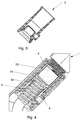
- the Fig. 2 shows the in the Fig. 1 II marked area of the sanitary fitting 1 in an enlarged view.
- the sealing element 5 arranged in the receptacle 3 can be seen here.
- the sealing element 5 seals an annular gap 9 between the tube 6 and the receptacle 3.
- the sealing element 5 has an at least partially radially inwardly extending sealing lip 10, which engages at least partially in a recess 14 of the tube 6.
- the sealing element 5 further comprises a radially outwardly extending outlet 7, to which the fluid through the sealing element 5 can be conducted and through which the fluid from the valve body 2 above in the Fig. 1 shown carrier 8 is derivable.
- the outlet 7 extends for this purpose through an opening 13 of the valve body. 2
- the Fig. 3 shows the first embodiment of the sealing element 5 in a longitudinal section.
- the Fig. 4 shows an enlarged portion of a sanitary fitting 1 with a second embodiment of a sealing element 5.
- the second embodiment differs from the first embodiment of the sealing element 5 only in that the sealing lip 10 partially between the tube 6 and an inner surface 11 of a cone 12 of the shower 4 extends.
Landscapes
- Health & Medical Sciences (AREA)
- Life Sciences & Earth Sciences (AREA)
- Engineering & Computer Science (AREA)
- Hydrology & Water Resources (AREA)
- Public Health (AREA)
- Water Supply & Treatment (AREA)
- Domestic Plumbing Installations (AREA)
- Bathtubs, Showers, And Their Attachments (AREA)
- Nozzles (AREA)
Abstract
Description
- Die vorliegende Erfindung betrifft eine Sanitärarmatur, die insbesondere für Waschbecken, Spülbecken, Duschen und/oder Badewannen verwendbar ist. Solche Sanitärarmaturen dienen insbesondere dem Mischen eines Kaltwassers und Warmwassers zu einem Mischwasser mit einer gewünschten Mischwassertemperatur und/oder dem Bereitstellen eines Fluidstroms.
- Aus dem Stand der Technik sind Sanitärarmaturen mit Brausen bekannt, bei denen die Brause aus einer Aufnahme eines Armaturengehäuses herausziehbar sind, um beispielsweise entfernte Bereiche eines Spülbeckens mit einem Fluidstrahl beziehungsweise Brausestrahl zu erreichen. Hierzu sind die herausziehbaren Brausen mit einem flexiblen Schlauch verbunden, durch den der Brause das Fluid, beispielsweise Wasser, zugeführt wird. Nachteilig an solchen Sanitärarmaturen ist, dass aus der Brause nachlaufendes Fluid entlang des Schlauchs unter einen Träger der Sanitärarmatur, wie zum Beispiel einem Unterschrank oder einer Arbeitsplatte, laufen kann und dort z.B. Feuchteschäden verursachen kann.
- Aufgabe der Erfindung ist daher, die mit Bezug auf den Stand der Technik geschilderten Probleme zumindest teilweise zu lösen und insbesondere eine Sanitärarmatur anzugeben, mit der eine unerwünschte Leckage bzw. Feuchteschäden vermieden werden können.
- Diese Aufgaben werden gelöst mit einer Sanitärarmatur gemäß den Merkmalen des unabhängigen Patentanspruchs. Weitere vorteilhafte Ausgestaltungen der Sanitärarmatur sind in den abhängig formulierten Patentansprüchen angegeben. Es ist darauf hinzuweisen, dass die in den abhängig formulierten Patentansprüchen einzeln aufgeführten Merkmale in beliebiger technologisch sinnvoller Weise miteinander kombiniert werden können und weitere Ausgestaltungen der Erfindung definieren. Darüber hinaus werden die in den Patentansprüchen angegebenen Merkmale in der Beschreibung näher präzisiert und erläutert, wobei weitere bevorzugte Ausgestaltungen der Erfindung dargestellt werden.
- Die erfindungsgemäße Sanitärarmatur weist ein Armaturengehäuse mit einer Aufnahme für eine herausziehbare Brause auf, wobei in der Aufnahme ein Dichtelement zum Ablenken eines an einem Schlauch der Brause abfließenden Fluids zu einem Auslauf angeordnet ist, sodass das Fluid oberhalb eines Trägers der Sanitärarmatur aus dem Armaturengehäuse ableitbar ist.
- Die Sanitärarmatur wird insbesondere im Zusammenhang mit Spülbecken, Waschbecken, Duschen und/oder Badwannen verwendet und weist ein Armaturengehäuse mit einer Aufnahme für eine herausziehbare Brause auf. Das Armaturengehäuse besteht zumindest teilweise aus Kunststoff und/oder Metall. Weiterhin ist das Armaturengehäuse insbesondere an einem Träger, wie zum Beispiel einer Arbeitsplatte oder einem Unterschrank, befestigbar oder angeordnet. Bei der Aufnahme handelt es sich insbesondere um eine Öffnung in dem Armaturengehäuse, in die die Brause zumindest teilweise einsteckbar ist bzw. in der die Brause teileweise aufgenommen und/oder (einseitig) fixierbar ist. Die Brause ist aus der Aufnahme herausziehbar. Zu diesem Zweck ist die Brause mit einem, insbesondere flexiblen, Schlauch an eine (entfernte bzw. unter dem Träger des Armaturengehäuses angeordnete) Fluidquelle angebunden, sodass der Brause ein Fluid, wie zum Beispiel Wasser, zuführbar ist. Der Schlauch erstreckt sich in diesem herausgezogenen Zustand ebenfalls durch die Öffnung des Armaturengehäuses. Zum Verhindern, dass aus der Brause nachlaufendes Fluid entlang des Schlauchs durch das Armaturengehäuse unter oder in den Träger läuft, ist in der Aufnahme ein Dichtelement angeordnet. Das Dichtelement ist insbesondere ein separates Bauteil, das bevorzugt zumindest teilweise rohrförmig ausgebildet und/oder zumindest teilweise eine Innenfläche der Aufnahme umgibt. Zudem ist das Dichtelement insbesondere in die Aufnahme einpressbar. Zu diesem Zweck kann das Dichtelement zumindest teilweise aus einem elastischem Material bestehen, sodass das Dichtelement durch Reibschluss in der Aufnahme befestigbar ist. Bei dem elastischen Material kann es sich beispielsweise um Gummi oder ein thermoplastisches Elastomer (TPE) handeln. Die Brause und/oder der Schlauch können zudem zumindest teilweise durch das Dichtelement hindurch geführt sein. Durch das Dichtelement ist ein außen an dem Schlauch entlanglaufendes Fluid (Leckage und/oder Nachlaufwasser vom Brausekopf) in der Aufnahme zu einem Auslauf des Armaturengehäuses ablenkbar, sodass das Fluid oberhalb des Trägers der Sanitärarmatur aus dem Armaturengehäuse ableitbar ist. Der Auslauf ist insbesondere nach Art eines Kanal oder einer Bohrung in dem Armaturengehäuse ausgeführt. Auf diese Weise kann einfach verhindert werden, dass das Fluid unterhalb und/oder in den Träger der Sanitärarmatur fließt und dort Feuchteschäden verursacht.
- Ebenfalls vorteilhaft ist es, wenn das Dichtelement einen Spalt zwischen dem Schlauch und der Aufnahme abdichtet. Der Schlauch verläuft insbesondere durch die Aufnahme beziehungsweise das Armaturengehäuse und bildet dort mit der Aufnahme den (Ring-)Spalt. Dieser (Ring-)Spalt wird durch das Dichtelement abgedichtet.
- Zudem ist es vorteilhaft, wenn das Dichtelement eine Dichtlippe aufweist. Die (hervorstehende und/oder verjüngte) Dichtlippe erstreckt sich bevorzugt von einer Innenfläche des Dichtelements zumindest teilweise radial nach innen und/oder umgreift den Schlauch der Brause anliegend, sodass die Dichtlippe durch einen an dem Schlauch ablaufenden Fluidstrom nicht überwunden werden kann.
- Weiterhin ist es vorteilhaft, wenn sich die Dichtlippe zumindest teilweise zwischen dem Schlauch und einer Innenfläche eines Konus der Brause erstreckt. Dies ist insbesondere dann der Fall, wenn sich die Brause in der Aufnahme befindet. Der Konus der Brause dient insbesondere als Einführhilfe der Brause in die Aufnahme. Der Konus ist hierzu insbesondere an einem einer Fluidöffnung der Brause gegenüberliegenden Ende der Brause angeordnet. Zudem mündet der Schlauch bevorzugt in den Konus und/oder erstreckt sich zumindest teilweise durch den Konus hindurch. Wird die Brause aus der Aufnahme herausgezogen, wird insbesondere auch die Dichtlippe zwischen dem Schlauch und der Innenfläche des Konus herausgezogen. Die Innenfläche des Konus beaufschlagt die Dichtlippe bevorzugt mit einem Druck in Richtung des Schlauchs, sodass die Dichtlippe eine besonders hohe Dichtigkeit aufweist.
- Darüber hinaus ist es vorteilhaft, wenn sich die Dichtlippe zumindest teilweise radial nach innen erstreckt.
- Ebenfalls vorteilhaft ist es, wenn sich der Auslauf zumindest teilweise durch eine Öffnung des Armaturengehäuses erstreckt. Der Auslauf erstreckt sich hierbei bevorzugt von dem Dichtelement radial nach außen und/oder ist einstückig mit dem Dichtelement ausgebildet.
- Darüber hinaus ist es vorteilhaft, wenn das Dichtelement mindestens teilweise in zumindest eine Vertiefung der Brause oder des Schlauchs eingreift. Hierdurch kann eine besonders hohe Dichtigkeit erzielt werden.
- Die Erfindung sowie das technische Umfeld werden nachfolgend anhand der Figuren näher erläutert. Es ist darauf hinzuweisen, dass die Figuren besonders bevorzugte Ausführungsvarianten der Erfindung zeigen, diese jedoch nicht darauf beschränkt ist. Dabei sind gleiche Bauteile in den Figuren mit denselben Bezugszeichen versehen. Es zeigen schematisch:
- Fig. 1:
- eine Sanitärarmatur in einer Schnittdarstellung;
- Fig. 2:
- eine vergrößerte Darstellung einer Aufnahme der Sanitärarmatur mit einer ersten Ausführungsvariante eines Dichtelements;
- Fig. 3:
- die erste Ausführungsvariante des Dichtelements in einem Längsschnitt; und
- Fig. 4:
- eine vergrößerte Darstellung einer Aufnahme einer Sanitärarmatur mit einer zweiten Ausführungsvariante eines Dichtelements.
- Die
Fig. 1 zeigt eine Sanitärarmatur 1 mit einem Armaturengehäuse 2, das an einem Träger 8 befestigt ist. Das Armaturengehäuse 2 weist eine Aufnahme 3 für eine Brause 4 auf. Die Brause 4 ist aus der Aufnahme 3 der Sanitärarmatur 1 herausziehbar. Hierzu ist die Brause 4 mit einem flexiblen Schlauch 6 verbunden, über den der Brause 4 ein Fluid zuführbar ist. Zur Verhinderung, dass aus der Brause 4 nachlaufendes Fluid entlang des Schlauchs 6 durch das Armaturengehäuse 2 unterhalb des Trägers 8 fließt und dort Feuchtigkeitsschäden verursacht, ist in der Aufnahme 3 ein Dichtelement 5 angeordnet. - Die
Fig. 2 zeigt den in derFig. 1 mit II markierten Bereich der Sanitärarmatur 1 in einer vergrößerten Darstellung. Zu erkennen ist hier insbesondere das in der Aufnahme 3 angeordnete Dichtelement 5. Das Dichtelement 5 dichtet einen ringförmigen Spalt 9 zwischen dem Schlauch 6 und der Aufnahme 3 ab. Hierzu weist das Dichtelement 5 eine sich zumindest teilweise radial nach innen erstreckende Dichtlippe 10 auf, die zumindest teilweise in eine Vertiefung 14 des Schlauchs 6 eingreift. Das Dichtelement 5 weist weiterhin einen sich radial nach außen erstreckenden Auslauf 7 auf, zu dem das Fluid durch das Dichtelement 5 leitbar und durch den das Fluid aus dem Armaturengehäuse 2 oberhalb des in derFig. 1 gezeigten Trägers 8 ableitbar ist. Der Auslauf 7 erstreckt sich hierzu durch eine Öffnung 13 des Armaturengehäuses 2. - Die
Fig. 3 zeigt die erste Ausführungsvariante des Dichtelements 5 in einem Längsschnitt. - Die
Fig. 4 zeigt einen vergrößerten Bereich einer Sanitärarmatur 1 mit einer zweiten Ausführungsvariante eines Dichtelements 5. Die zweite Ausführungsvariante unterscheidet sich von der ersten Ausführungsvariante des Dichtelements 5 lediglich dadurch, dass die Dichtlippe 10 sich teilweise zwischen dem Schlauch 6 und einer Innenfläche 11 eines Konus 12 der Brause 4 erstreckt. - Mit der vorgeschlagenen Sanitärarmatur sind insbesondere Feuchteschäden an Trägern der Sanitärarmatur verhinderbar.
-
- 1
- Sanitärarmatur
- 2
- Armaturengehäuse
- 3
- Aufnahme
- 4
- Brause
- 5
- Dichtelement
- 6
- Schlauch
- 7
- Auslauf
- 8
- Träger
- 9
- Spalt
- 10
- Dichtlippe
- 11
- Innenfläche
- 12
- Konus
- 13
- Öffnung
- 14
- Vertiefung
Claims (7)
- Sanitärarmatur (1), aufweisend ein Armaturengehäuse (2) mit einer Aufnahme (3) für eine herausziehbaren Brause (4), wobei in der Aufnahme (3) ein Dichtelement (5) zum Ablenken eines an einem Schlauch (6) der Brause (4) abfließenden Fluids zu einem Auslauf (7) angeordnet ist, sodass das Fluid oberhalb eines Trägers (8) der Sanitärarmatur (1) aus dem Armaturengehäuse (2) ableitbar ist.
- Sanitärarmatur (1) nach Patentanspruch 1, wobei das Dichtelement (5) einen Spalt (9) zwischen dem Schlauch (6) und der Aufnahme (3) abdichtet.
- Sanitärarmatur (1) nach einem der vorhergehenden Patentansprüche, wobei das Dichtelement (5) eine Dichtlippe (10) aufweist.
- Sanitärarmatur (1) nach Patentanspruch 3, wobei sich die Dichtlippe (10) zumindest teilweise zwischen dem Schlauch (6) und einer Innenfläche (11) eines Konus (12) der Brause (4) erstreckt.
- Sanitärarmatur (1) nach einem der Patentansprüche 3 oder 4, wobei sich die Dichtlippe (10) zumindest teilweise radial nach innen erstreckt.
- Sanitärarmatur (1) nach einem der vorhergehenden Patentansprüche, wobei der Auslauf (7) sich zumindest teilweise durch eine Öffnung (13) des Armaturengehäuses (2) erstreckt.
- Sanitärarmatur (1) nach einem der vorhergehenden Patentansprüche, wobei das Dichtelement (5) mindestens teilweise in zumindest eine Vertiefung (14) der Brause (4) oder des Schlauchs (6) eingreift.
Applications Claiming Priority (1)
| Application Number | Priority Date | Filing Date | Title |
|---|---|---|---|
| DE102015002590.2A DE102015002590A1 (de) | 2015-02-27 | 2015-02-27 | Sanitärarmatur mit Dichtelement für herausziehbare Brause |
Publications (2)
| Publication Number | Publication Date |
|---|---|
| EP3061876A1 true EP3061876A1 (de) | 2016-08-31 |
| EP3061876B1 EP3061876B1 (de) | 2019-09-11 |
Family
ID=55300349
Family Applications (1)
| Application Number | Title | Priority Date | Filing Date |
|---|---|---|---|
| EP16000261.4A Active EP3061876B1 (de) | 2015-02-27 | 2016-02-03 | Sanitärarmatur mit herausziehbarer brause |
Country Status (3)
| Country | Link |
|---|---|
| EP (1) | EP3061876B1 (de) |
| JP (1) | JP2016160748A (de) |
| DE (1) | DE102015002590A1 (de) |
Families Citing this family (2)
| Publication number | Priority date | Publication date | Assignee | Title |
|---|---|---|---|---|
| DE102019219489A1 (de) * | 2019-12-12 | 2021-06-17 | Hansgrohe Se | Sanitäre Auszugsschlaucharmatur |
| CN114916849A (zh) * | 2022-05-27 | 2022-08-19 | 佛山市润恒卫浴产品有限公司 | 花洒防滴水安装结构 |
Citations (1)
| Publication number | Priority date | Publication date | Assignee | Title |
|---|---|---|---|---|
| EP0731229A2 (de) * | 1995-03-08 | 1996-09-11 | Hans Grohe GmbH & Co. KG | Brausehalter |
Family Cites Families (2)
| Publication number | Priority date | Publication date | Assignee | Title |
|---|---|---|---|---|
| DE9217207U1 (de) * | 1992-12-16 | 1994-04-14 | Reich GmbH Regel- und Sicherheitstechnik, 35713 Eschenburg | Spritzwasserschutz |
| IT230426Y1 (it) * | 1993-09-24 | 1999-06-07 | Teuco Guzzini Srl | Dispositivo di sostegno e scorrimento per doccia estraibile |
-
2015
- 2015-02-27 DE DE102015002590.2A patent/DE102015002590A1/de not_active Withdrawn
-
2016
- 2016-02-03 EP EP16000261.4A patent/EP3061876B1/de active Active
- 2016-02-26 JP JP2016035895A patent/JP2016160748A/ja active Pending
Patent Citations (1)
| Publication number | Priority date | Publication date | Assignee | Title |
|---|---|---|---|---|
| EP0731229A2 (de) * | 1995-03-08 | 1996-09-11 | Hans Grohe GmbH & Co. KG | Brausehalter |
Also Published As
| Publication number | Publication date |
|---|---|
| JP2016160748A (ja) | 2016-09-05 |
| DE102015002590A1 (de) | 2016-09-29 |
| EP3061876B1 (de) | 2019-09-11 |
Similar Documents
| Publication | Publication Date | Title |
|---|---|---|
| DE102014104623B4 (de) | Werkzeugaufnahme | |
| EP2582890B1 (de) | Sanitäre einsetzeinheit sowie brausearmatur mit einer sanitären einsetzeinheit | |
| EP3085838A1 (de) | Sanitärarmatur für zumindest zwei fluide | |
| DE102017101566B3 (de) | Schlauchanschlussanordnung, Verwendung einer Schlauchanschlussanordnung und Sanitärarmatur | |
| EP4107337B1 (de) | Sanitärarmatur sowie verfahren zur montage einer derartigen sanitärarmatur | |
| WO2020053408A1 (de) | Auslauf für eine wasserarmatur | |
| DE202017105094U1 (de) | Sanitäre Thermostatarmatur | |
| EP3061876B1 (de) | Sanitärarmatur mit herausziehbarer brause | |
| EP3759285A1 (de) | Kugelgelenk | |
| DE102010023962A1 (de) | Dichtring, Durchflussmengenregler sowie Brausearmatur mit einem Durchflussmengenregler | |
| DE102014001818A1 (de) | Anschlussstück für einen Auslauf einer Sanitärarmatur | |
| EP1818461A1 (de) | Sanitärarmatur | |
| DE102010023664B4 (de) | Sanitäre Auslaufarmatur | |
| EP3262241A1 (de) | Sanitärarmatur mit einer arretierung für eine fluidleitung | |
| EP3546421A1 (de) | Zapfvorrichtung aufweisend einen düseneinsatz mit einer prallwand | |
| EP3141665B1 (de) | Sanitärarmatur mit wasserführendem schlauch | |
| DE1775660A1 (de) | Mischventil mit einem eine Verteilerkammer aufweisenden Einsatz | |
| DE202015005582U1 (de) | Reinigungsdüse | |
| EP3310971B1 (de) | Sanitärarmatur für mehrere fluide | |
| EP3330443A1 (de) | Sanitärarmatur mit zumindest einem ein rückschlagventil aufweisenden anschlussstück | |
| EP4198213B1 (de) | Sanitärarmatur mit einer mischkartusche | |
| DE102015000198A1 (de) | Sanitärarmatur mit optimierter Fluidleitung | |
| EP4397817A1 (de) | Sanitärarmatur | |
| DE102005046673B3 (de) | Einbauteil | |
| EP4249690A1 (de) | Sanitärarmatur |
Legal Events
| Date | Code | Title | Description |
|---|---|---|---|
| PUAI | Public reference made under article 153(3) epc to a published international application that has entered the european phase |
Free format text: ORIGINAL CODE: 0009012 |
|
| AK | Designated contracting states |
Kind code of ref document: A1 Designated state(s): AL AT BE BG CH CY CZ DE DK EE ES FI FR GB GR HR HU IE IS IT LI LT LU LV MC MK MT NL NO PL PT RO RS SE SI SK SM TR |
|
| AX | Request for extension of the european patent |
Extension state: BA ME |
|
| STAA | Information on the status of an ep patent application or granted ep patent |
Free format text: STATUS: REQUEST FOR EXAMINATION WAS MADE |
|
| 17P | Request for examination filed |
Effective date: 20170227 |
|
| RBV | Designated contracting states (corrected) |
Designated state(s): AL AT BE BG CH CY CZ DE DK EE ES FI FR GB GR HR HU IE IS IT LI LT LU LV MC MK MT NL NO PL PT RO RS SE SI SK SM TR |
|
| STAA | Information on the status of an ep patent application or granted ep patent |
Free format text: STATUS: EXAMINATION IS IN PROGRESS |
|
| RIC1 | Information provided on ipc code assigned before grant |
Ipc: E03C 1/04 20060101AFI20171124BHEP |
|
| 17Q | First examination report despatched |
Effective date: 20171211 |
|
| GRAP | Despatch of communication of intention to grant a patent |
Free format text: ORIGINAL CODE: EPIDOSNIGR1 |
|
| STAA | Information on the status of an ep patent application or granted ep patent |
Free format text: STATUS: GRANT OF PATENT IS INTENDED |
|
| INTG | Intention to grant announced |
Effective date: 20190404 |
|
| GRAS | Grant fee paid |
Free format text: ORIGINAL CODE: EPIDOSNIGR3 |
|
| GRAA | (expected) grant |
Free format text: ORIGINAL CODE: 0009210 |
|
| STAA | Information on the status of an ep patent application or granted ep patent |
Free format text: STATUS: THE PATENT HAS BEEN GRANTED |
|
| AK | Designated contracting states |
Kind code of ref document: B1 Designated state(s): AL AT BE BG CH CY CZ DE DK EE ES FI FR GB GR HR HU IE IS IT LI LT LU LV MC MK MT NL NO PL PT RO RS SE SI SK SM TR |
|
| REG | Reference to a national code |
Ref country code: GB Ref legal event code: FG4D Free format text: NOT ENGLISH |
|
| REG | Reference to a national code |
Ref country code: CH Ref legal event code: EP |
|
| REG | Reference to a national code |
Ref country code: AT Ref legal event code: REF Ref document number: 1178623 Country of ref document: AT Kind code of ref document: T Effective date: 20190915 |
|
| REG | Reference to a national code |
Ref country code: DE Ref legal event code: R096 Ref document number: 502016006494 Country of ref document: DE Ref country code: IE Ref legal event code: FG4D Free format text: LANGUAGE OF EP DOCUMENT: GERMAN |
|
| REG | Reference to a national code |
Ref country code: NL Ref legal event code: FP |
|
| REG | Reference to a national code |
Ref country code: LT Ref legal event code: MG4D |
|
| PG25 | Lapsed in a contracting state [announced via postgrant information from national office to epo] |
Ref country code: BG Free format text: LAPSE BECAUSE OF FAILURE TO SUBMIT A TRANSLATION OF THE DESCRIPTION OR TO PAY THE FEE WITHIN THE PRESCRIBED TIME-LIMIT Effective date: 20191211 Ref country code: HR Free format text: LAPSE BECAUSE OF FAILURE TO SUBMIT A TRANSLATION OF THE DESCRIPTION OR TO PAY THE FEE WITHIN THE PRESCRIBED TIME-LIMIT Effective date: 20190911 Ref country code: LT Free format text: LAPSE BECAUSE OF FAILURE TO SUBMIT A TRANSLATION OF THE DESCRIPTION OR TO PAY THE FEE WITHIN THE PRESCRIBED TIME-LIMIT Effective date: 20190911 Ref country code: NO Free format text: LAPSE BECAUSE OF FAILURE TO SUBMIT A TRANSLATION OF THE DESCRIPTION OR TO PAY THE FEE WITHIN THE PRESCRIBED TIME-LIMIT Effective date: 20191211 Ref country code: FI Free format text: LAPSE BECAUSE OF FAILURE TO SUBMIT A TRANSLATION OF THE DESCRIPTION OR TO PAY THE FEE WITHIN THE PRESCRIBED TIME-LIMIT Effective date: 20190911 Ref country code: SE Free format text: LAPSE BECAUSE OF FAILURE TO SUBMIT A TRANSLATION OF THE DESCRIPTION OR TO PAY THE FEE WITHIN THE PRESCRIBED TIME-LIMIT Effective date: 20190911 |
|
| PG25 | Lapsed in a contracting state [announced via postgrant information from national office to epo] |
Ref country code: RS Free format text: LAPSE BECAUSE OF FAILURE TO SUBMIT A TRANSLATION OF THE DESCRIPTION OR TO PAY THE FEE WITHIN THE PRESCRIBED TIME-LIMIT Effective date: 20190911 Ref country code: LV Free format text: LAPSE BECAUSE OF FAILURE TO SUBMIT A TRANSLATION OF THE DESCRIPTION OR TO PAY THE FEE WITHIN THE PRESCRIBED TIME-LIMIT Effective date: 20190911 Ref country code: GR Free format text: LAPSE BECAUSE OF FAILURE TO SUBMIT A TRANSLATION OF THE DESCRIPTION OR TO PAY THE FEE WITHIN THE PRESCRIBED TIME-LIMIT Effective date: 20191212 Ref country code: ES Free format text: LAPSE BECAUSE OF FAILURE TO SUBMIT A TRANSLATION OF THE DESCRIPTION OR TO PAY THE FEE WITHIN THE PRESCRIBED TIME-LIMIT Effective date: 20190911 Ref country code: AL Free format text: LAPSE BECAUSE OF FAILURE TO SUBMIT A TRANSLATION OF THE DESCRIPTION OR TO PAY THE FEE WITHIN THE PRESCRIBED TIME-LIMIT Effective date: 20190911 |
|
| PG25 | Lapsed in a contracting state [announced via postgrant information from national office to epo] |
Ref country code: RO Free format text: LAPSE BECAUSE OF FAILURE TO SUBMIT A TRANSLATION OF THE DESCRIPTION OR TO PAY THE FEE WITHIN THE PRESCRIBED TIME-LIMIT Effective date: 20190911 Ref country code: IT Free format text: LAPSE BECAUSE OF FAILURE TO SUBMIT A TRANSLATION OF THE DESCRIPTION OR TO PAY THE FEE WITHIN THE PRESCRIBED TIME-LIMIT Effective date: 20190911 Ref country code: EE Free format text: LAPSE BECAUSE OF FAILURE TO SUBMIT A TRANSLATION OF THE DESCRIPTION OR TO PAY THE FEE WITHIN THE PRESCRIBED TIME-LIMIT Effective date: 20190911 Ref country code: PT Free format text: LAPSE BECAUSE OF FAILURE TO SUBMIT A TRANSLATION OF THE DESCRIPTION OR TO PAY THE FEE WITHIN THE PRESCRIBED TIME-LIMIT Effective date: 20200113 Ref country code: PL Free format text: LAPSE BECAUSE OF FAILURE TO SUBMIT A TRANSLATION OF THE DESCRIPTION OR TO PAY THE FEE WITHIN THE PRESCRIBED TIME-LIMIT Effective date: 20190911 |
|
| PGFP | Annual fee paid to national office [announced via postgrant information from national office to epo] |
Ref country code: NL Payment date: 20200219 Year of fee payment: 5 Ref country code: DE Payment date: 20200219 Year of fee payment: 5 |
|
| PG25 | Lapsed in a contracting state [announced via postgrant information from national office to epo] |
Ref country code: CZ Free format text: LAPSE BECAUSE OF FAILURE TO SUBMIT A TRANSLATION OF THE DESCRIPTION OR TO PAY THE FEE WITHIN THE PRESCRIBED TIME-LIMIT Effective date: 20190911 Ref country code: IS Free format text: LAPSE BECAUSE OF FAILURE TO SUBMIT A TRANSLATION OF THE DESCRIPTION OR TO PAY THE FEE WITHIN THE PRESCRIBED TIME-LIMIT Effective date: 20200224 Ref country code: SK Free format text: LAPSE BECAUSE OF FAILURE TO SUBMIT A TRANSLATION OF THE DESCRIPTION OR TO PAY THE FEE WITHIN THE PRESCRIBED TIME-LIMIT Effective date: 20190911 Ref country code: SM Free format text: LAPSE BECAUSE OF FAILURE TO SUBMIT A TRANSLATION OF THE DESCRIPTION OR TO PAY THE FEE WITHIN THE PRESCRIBED TIME-LIMIT Effective date: 20190911 |
|
| REG | Reference to a national code |
Ref country code: DE Ref legal event code: R097 Ref document number: 502016006494 Country of ref document: DE |
|
| PGFP | Annual fee paid to national office [announced via postgrant information from national office to epo] |
Ref country code: FR Payment date: 20200219 Year of fee payment: 5 |
|
| PLBE | No opposition filed within time limit |
Free format text: ORIGINAL CODE: 0009261 |
|
| STAA | Information on the status of an ep patent application or granted ep patent |
Free format text: STATUS: NO OPPOSITION FILED WITHIN TIME LIMIT |
|
| PG2D | Information on lapse in contracting state deleted |
Ref country code: IS |
|
| PG25 | Lapsed in a contracting state [announced via postgrant information from national office to epo] |
Ref country code: DK Free format text: LAPSE BECAUSE OF FAILURE TO SUBMIT A TRANSLATION OF THE DESCRIPTION OR TO PAY THE FEE WITHIN THE PRESCRIBED TIME-LIMIT Effective date: 20190911 Ref country code: IS Free format text: LAPSE BECAUSE OF FAILURE TO SUBMIT A TRANSLATION OF THE DESCRIPTION OR TO PAY THE FEE WITHIN THE PRESCRIBED TIME-LIMIT Effective date: 20200112 |
|
| 26N | No opposition filed |
Effective date: 20200615 |
|
| PG25 | Lapsed in a contracting state [announced via postgrant information from national office to epo] |
Ref country code: SI Free format text: LAPSE BECAUSE OF FAILURE TO SUBMIT A TRANSLATION OF THE DESCRIPTION OR TO PAY THE FEE WITHIN THE PRESCRIBED TIME-LIMIT Effective date: 20190911 |
|
| REG | Reference to a national code |
Ref country code: CH Ref legal event code: PL |
|
| GBPC | Gb: european patent ceased through non-payment of renewal fee |
Effective date: 20200203 |
|
| REG | Reference to a national code |
Ref country code: BE Ref legal event code: MM Effective date: 20200229 |
|
| PG25 | Lapsed in a contracting state [announced via postgrant information from national office to epo] |
Ref country code: MC Free format text: LAPSE BECAUSE OF FAILURE TO SUBMIT A TRANSLATION OF THE DESCRIPTION OR TO PAY THE FEE WITHIN THE PRESCRIBED TIME-LIMIT Effective date: 20190911 Ref country code: LU Free format text: LAPSE BECAUSE OF NON-PAYMENT OF DUE FEES Effective date: 20200203 |
|
| PG25 | Lapsed in a contracting state [announced via postgrant information from national office to epo] |
Ref country code: CH Free format text: LAPSE BECAUSE OF NON-PAYMENT OF DUE FEES Effective date: 20200229 Ref country code: LI Free format text: LAPSE BECAUSE OF NON-PAYMENT OF DUE FEES Effective date: 20200229 |
|
| PG25 | Lapsed in a contracting state [announced via postgrant information from national office to epo] |
Ref country code: IE Free format text: LAPSE BECAUSE OF NON-PAYMENT OF DUE FEES Effective date: 20200203 Ref country code: GB Free format text: LAPSE BECAUSE OF NON-PAYMENT OF DUE FEES Effective date: 20200203 |
|
| PG25 | Lapsed in a contracting state [announced via postgrant information from national office to epo] |
Ref country code: BE Free format text: LAPSE BECAUSE OF NON-PAYMENT OF DUE FEES Effective date: 20200229 |
|
| REG | Reference to a national code |
Ref country code: DE Ref legal event code: R119 Ref document number: 502016006494 Country of ref document: DE |
|
| REG | Reference to a national code |
Ref country code: NL Ref legal event code: MM Effective date: 20210301 |
|
| PG25 | Lapsed in a contracting state [announced via postgrant information from national office to epo] |
Ref country code: NL Free format text: LAPSE BECAUSE OF NON-PAYMENT OF DUE FEES Effective date: 20210301 |
|
| PG25 | Lapsed in a contracting state [announced via postgrant information from national office to epo] |
Ref country code: FR Free format text: LAPSE BECAUSE OF NON-PAYMENT OF DUE FEES Effective date: 20210228 Ref country code: DE Free format text: LAPSE BECAUSE OF NON-PAYMENT OF DUE FEES Effective date: 20210901 |
|
| REG | Reference to a national code |
Ref country code: AT Ref legal event code: MM01 Ref document number: 1178623 Country of ref document: AT Kind code of ref document: T Effective date: 20210203 |
|
| PG25 | Lapsed in a contracting state [announced via postgrant information from national office to epo] |
Ref country code: AT Free format text: LAPSE BECAUSE OF NON-PAYMENT OF DUE FEES Effective date: 20210203 |
|
| PG25 | Lapsed in a contracting state [announced via postgrant information from national office to epo] |
Ref country code: TR Free format text: LAPSE BECAUSE OF FAILURE TO SUBMIT A TRANSLATION OF THE DESCRIPTION OR TO PAY THE FEE WITHIN THE PRESCRIBED TIME-LIMIT Effective date: 20190911 Ref country code: MT Free format text: LAPSE BECAUSE OF FAILURE TO SUBMIT A TRANSLATION OF THE DESCRIPTION OR TO PAY THE FEE WITHIN THE PRESCRIBED TIME-LIMIT Effective date: 20190911 Ref country code: CY Free format text: LAPSE BECAUSE OF FAILURE TO SUBMIT A TRANSLATION OF THE DESCRIPTION OR TO PAY THE FEE WITHIN THE PRESCRIBED TIME-LIMIT Effective date: 20190911 |
|
| PG25 | Lapsed in a contracting state [announced via postgrant information from national office to epo] |
Ref country code: MK Free format text: LAPSE BECAUSE OF FAILURE TO SUBMIT A TRANSLATION OF THE DESCRIPTION OR TO PAY THE FEE WITHIN THE PRESCRIBED TIME-LIMIT Effective date: 20190911 |