EP3061384A1 - Image capturing unit and endoscope - Google Patents
Image capturing unit and endoscope Download PDFInfo
- Publication number
- EP3061384A1 EP3061384A1 EP15796750.6A EP15796750A EP3061384A1 EP 3061384 A1 EP3061384 A1 EP 3061384A1 EP 15796750 A EP15796750 A EP 15796750A EP 3061384 A1 EP3061384 A1 EP 3061384A1
- Authority
- EP
- European Patent Office
- Prior art keywords
- image pickup
- optical member
- cover glass
- face
- light blocking
- Prior art date
- Legal status (The legal status is an assumption and is not a legal conclusion. Google has not performed a legal analysis and makes no representation as to the accuracy of the status listed.)
- Granted
Links
- 230000003287 optical effect Effects 0.000 claims abstract description 113
- 239000006059 cover glass Substances 0.000 claims abstract description 51
- 230000000903 blocking effect Effects 0.000 claims abstract description 50
- 230000015572 biosynthetic process Effects 0.000 claims abstract description 29
- 230000000007 visual effect Effects 0.000 claims abstract description 23
- 239000010409 thin film Substances 0.000 claims description 3
- 238000003780 insertion Methods 0.000 description 7
- 230000037431 insertion Effects 0.000 description 7
- 238000005452 bending Methods 0.000 description 4
- 230000005540 biological transmission Effects 0.000 description 4
- 238000010586 diagram Methods 0.000 description 4
- 238000012986 modification Methods 0.000 description 4
- 230000004048 modification Effects 0.000 description 4
- 239000000853 adhesive Substances 0.000 description 3
- 230000001070 adhesive effect Effects 0.000 description 3
- 230000002411 adverse Effects 0.000 description 3
- 239000011521 glass Substances 0.000 description 3
- 230000001629 suppression Effects 0.000 description 3
- 239000002184 metal Substances 0.000 description 2
- 238000007789 sealing Methods 0.000 description 2
- 238000007740 vapor deposition Methods 0.000 description 2
- 230000007274 generation of a signal involved in cell-cell signaling Effects 0.000 description 1
- 230000012447 hatching Effects 0.000 description 1
- 238000001727 in vivo Methods 0.000 description 1
- 239000000463 material Substances 0.000 description 1
- 238000000034 method Methods 0.000 description 1
- 239000011347 resin Substances 0.000 description 1
- 229920005989 resin Polymers 0.000 description 1
- 239000012780 transparent material Substances 0.000 description 1
Images






Classifications
-
- G—PHYSICS
- G02—OPTICS
- G02B—OPTICAL ELEMENTS, SYSTEMS OR APPARATUS
- G02B23/00—Telescopes, e.g. binoculars; Periscopes; Instruments for viewing the inside of hollow bodies; Viewfinders; Optical aiming or sighting devices
- G02B23/24—Instruments or systems for viewing the inside of hollow bodies, e.g. fibrescopes
- G02B23/2407—Optical details
- G02B23/2423—Optical details of the distal end
- G02B23/243—Objectives for endoscopes
-
- A—HUMAN NECESSITIES
- A61—MEDICAL OR VETERINARY SCIENCE; HYGIENE
- A61B—DIAGNOSIS; SURGERY; IDENTIFICATION
- A61B1/00—Instruments for performing medical examinations of the interior of cavities or tubes of the body by visual or photographical inspection, e.g. endoscopes; Illuminating arrangements therefor
-
- A—HUMAN NECESSITIES
- A61—MEDICAL OR VETERINARY SCIENCE; HYGIENE
- A61B—DIAGNOSIS; SURGERY; IDENTIFICATION
- A61B1/00—Instruments for performing medical examinations of the interior of cavities or tubes of the body by visual or photographical inspection, e.g. endoscopes; Illuminating arrangements therefor
- A61B1/00064—Constructional details of the endoscope body
- A61B1/00071—Insertion part of the endoscope body
- A61B1/0008—Insertion part of the endoscope body characterised by distal tip features
- A61B1/00096—Optical elements
-
- A—HUMAN NECESSITIES
- A61—MEDICAL OR VETERINARY SCIENCE; HYGIENE
- A61B—DIAGNOSIS; SURGERY; IDENTIFICATION
- A61B1/00—Instruments for performing medical examinations of the interior of cavities or tubes of the body by visual or photographical inspection, e.g. endoscopes; Illuminating arrangements therefor
- A61B1/00112—Connection or coupling means
- A61B1/00114—Electrical cables in or with an endoscope
-
- A—HUMAN NECESSITIES
- A61—MEDICAL OR VETERINARY SCIENCE; HYGIENE
- A61B—DIAGNOSIS; SURGERY; IDENTIFICATION
- A61B1/00—Instruments for performing medical examinations of the interior of cavities or tubes of the body by visual or photographical inspection, e.g. endoscopes; Illuminating arrangements therefor
- A61B1/005—Flexible endoscopes
- A61B1/0051—Flexible endoscopes with controlled bending of insertion part
- A61B1/0052—Constructional details of control elements, e.g. handles
-
- A—HUMAN NECESSITIES
- A61—MEDICAL OR VETERINARY SCIENCE; HYGIENE
- A61B—DIAGNOSIS; SURGERY; IDENTIFICATION
- A61B1/00—Instruments for performing medical examinations of the interior of cavities or tubes of the body by visual or photographical inspection, e.g. endoscopes; Illuminating arrangements therefor
- A61B1/04—Instruments for performing medical examinations of the interior of cavities or tubes of the body by visual or photographical inspection, e.g. endoscopes; Illuminating arrangements therefor combined with photographic or television appliances
-
- A—HUMAN NECESSITIES
- A61—MEDICAL OR VETERINARY SCIENCE; HYGIENE
- A61B—DIAGNOSIS; SURGERY; IDENTIFICATION
- A61B1/00—Instruments for performing medical examinations of the interior of cavities or tubes of the body by visual or photographical inspection, e.g. endoscopes; Illuminating arrangements therefor
- A61B1/04—Instruments for performing medical examinations of the interior of cavities or tubes of the body by visual or photographical inspection, e.g. endoscopes; Illuminating arrangements therefor combined with photographic or television appliances
- A61B1/05—Instruments for performing medical examinations of the interior of cavities or tubes of the body by visual or photographical inspection, e.g. endoscopes; Illuminating arrangements therefor combined with photographic or television appliances characterised by the image sensor, e.g. camera, being in the distal end portion
-
- A—HUMAN NECESSITIES
- A61—MEDICAL OR VETERINARY SCIENCE; HYGIENE
- A61B—DIAGNOSIS; SURGERY; IDENTIFICATION
- A61B1/00—Instruments for performing medical examinations of the interior of cavities or tubes of the body by visual or photographical inspection, e.g. endoscopes; Illuminating arrangements therefor
- A61B1/06—Instruments for performing medical examinations of the interior of cavities or tubes of the body by visual or photographical inspection, e.g. endoscopes; Illuminating arrangements therefor with illuminating arrangements
- A61B1/0661—Endoscope light sources
- A61B1/0676—Endoscope light sources at distal tip of an endoscope
-
- G—PHYSICS
- G02—OPTICS
- G02B—OPTICAL ELEMENTS, SYSTEMS OR APPARATUS
- G02B13/00—Optical objectives specially designed for the purposes specified below
-
- G—PHYSICS
- G02—OPTICS
- G02B—OPTICAL ELEMENTS, SYSTEMS OR APPARATUS
- G02B23/00—Telescopes, e.g. binoculars; Periscopes; Instruments for viewing the inside of hollow bodies; Viewfinders; Optical aiming or sighting devices
- G02B23/24—Instruments or systems for viewing the inside of hollow bodies, e.g. fibrescopes
-
- G—PHYSICS
- G02—OPTICS
- G02B—OPTICAL ELEMENTS, SYSTEMS OR APPARATUS
- G02B23/00—Telescopes, e.g. binoculars; Periscopes; Instruments for viewing the inside of hollow bodies; Viewfinders; Optical aiming or sighting devices
- G02B23/24—Instruments or systems for viewing the inside of hollow bodies, e.g. fibrescopes
- G02B23/2407—Optical details
- G02B23/2446—Optical details of the image relay
-
- G—PHYSICS
- G02—OPTICS
- G02B—OPTICAL ELEMENTS, SYSTEMS OR APPARATUS
- G02B23/00—Telescopes, e.g. binoculars; Periscopes; Instruments for viewing the inside of hollow bodies; Viewfinders; Optical aiming or sighting devices
- G02B23/24—Instruments or systems for viewing the inside of hollow bodies, e.g. fibrescopes
- G02B23/2476—Non-optical details, e.g. housings, mountings, supports
-
- G—PHYSICS
- G02—OPTICS
- G02B—OPTICAL ELEMENTS, SYSTEMS OR APPARATUS
- G02B5/00—Optical elements other than lenses
- G02B5/005—Diaphragms
-
- G—PHYSICS
- G02—OPTICS
- G02B—OPTICAL ELEMENTS, SYSTEMS OR APPARATUS
- G02B7/00—Mountings, adjusting means, or light-tight connections, for optical elements
- G02B7/02—Mountings, adjusting means, or light-tight connections, for optical elements for lenses
-
- H—ELECTRICITY
- H04—ELECTRIC COMMUNICATION TECHNIQUE
- H04N—PICTORIAL COMMUNICATION, e.g. TELEVISION
- H04N23/00—Cameras or camera modules comprising electronic image sensors; Control thereof
- H04N23/56—Cameras or camera modules comprising electronic image sensors; Control thereof provided with illuminating means
-
- A—HUMAN NECESSITIES
- A61—MEDICAL OR VETERINARY SCIENCE; HYGIENE
- A61B—DIAGNOSIS; SURGERY; IDENTIFICATION
- A61B1/00—Instruments for performing medical examinations of the interior of cavities or tubes of the body by visual or photographical inspection, e.g. endoscopes; Illuminating arrangements therefor
- A61B1/00163—Optical arrangements
- A61B1/00186—Optical arrangements with imaging filters
-
- H—ELECTRICITY
- H04—ELECTRIC COMMUNICATION TECHNIQUE
- H04N—PICTORIAL COMMUNICATION, e.g. TELEVISION
- H04N23/00—Cameras or camera modules comprising electronic image sensors; Control thereof
- H04N23/50—Constructional details
- H04N23/555—Constructional details for picking-up images in sites, inaccessible due to their dimensions or hazardous conditions, e.g. endoscopes or borescopes
Definitions
- the present invention relates to an image pickup unit and an endoscope including an objective lens unit and an image pickup device.
- an endoscope including, in a distal end portion of an insertion section insertable from an outside to the inside of the organism or the structure, an image pickup unit for picking up an optical image is used in, for example, a medical field and an industrial field.
- an image pickup unit of an endoscope includes an objective lens unit that picks up an object image and an image pickup device disposed in an image forming surface of the objective lens unit.
- a cover glass 23 for sealing a light receiving surface 22a is fixed on a light receiving surface 22a of an image pickup device 22.
- An optical member 24 made of a transparent member such as glass is stuck to a front surface of the cover glass 23.
- the optical member 24 is fit in a fitting hole 21a formed in a holding frame 21 fixed to a not-shown objective lens unit and is fixed by an adhesive or the like.
- some image pickup units include a configuration in which the image pickup device 22 is fixed to, via the optical member 24, the holding frame 21 fixed to the objective lens unit.
- the image pickup unit including the optical member 24 fit in a rear end of the holding frame 21 fixed to the objective lens unit and the image pickup device 22 fixed to the optical member 24 as shown in Fig. 13 , it is necessary to reduce an external shape of the optical member 24 in order to realize a reduction in size (a reduction in diameter) of the image pickup unit. If the external shape of the optical member 24 is reduced, it is possible to reduce an external shape of a rear end portion of the holding frame 21 as well.
- a light blocking member 25 is disposed on a surface (a surface on an image side) behind the optical member 24, the ray L10 reflected on the side surface of the optical member 24 can be blocked.
- a ray L11 reflected on a protrusion section 21b for bumping the optical member 24 provided in the holding frame 21 is made incident on the pixel formation region 22b of the image pickup device 22 and causes flares.
- the image pickup unit is increased in size (increased in diameter) as explained above.
- the present invention has been devised in view of the points explained above and it is an object of the present invention to provide an image pickup unit and an endoscope that achieve both of a reduction in size and suppression of flares.
- An image pickup unit includes: an objective lens unit; a rectangular or square cover glass fixed on a light receiving surface, which is a front end face of an image pickup device; a circular optical member stuck to a front end face of the cover glass and having a diameter smaller than a diagonal line length of the cover glass; a holding frame fixed to the objective lens unit, and having a circular fitting hole in which the optical member is fit from a rear; a projecting section projecting toward a radial direction inner side in the holding frame; a first light blocking member disposed in a front of the optical member to block visual field external light reflecting on an inner wall surface of the projecting section and traveling to an inside of a pixel formation region of the image pickup device; and a second light blocking member disposed between a rear end face of the optical member and a front end face of the cover glass to block the visual field external light reflecting on a side surface of the optical member and having an angle toward the inside of the pixel formation region.
- An endoscope includes:
- the endoscope 101 in the present embodiment includes a configuration introducible into a subject such as a human body and capable of optically picking up an image of a predetermined observation part in the subject.
- the object into which the endoscope 101 is introduced is not limited to the human body and may be other organisms or may be an artificial object such as a machine or a structure.
- the endoscope 101 in the present embodiment is mainly configured by an elongated insertion section 102 introduced into an inside of the object, an operation section 103 located at a proximal end of the insertion section 102, and a universal cord 104 extending from a side portion of the operation section 103.
- the insertion section 102 is configured by concatenating a distal end portion 110 disposed at a distal end, a bendable bending section 109 disposed on a proximal end side of the distal end portion 110, and a flexible tube section 108 having flexibility disposed on a proximal end side of the bending section 109 and connected to a distal end side of the operation section 103.
- An image pickup unit 1 including an objective lens unit 10 and an image pickup device 2 is disposed at the distal end portion 110.
- an illumination-light emitting section that emits light for illuminating an object of the image pickup unit 1 is also provided at the distal end portion 110.
- the endoscope 101 may be an endoscope of a form called rigid endoscope not including a part having flexibility in an insertion section.
- an angle operation knob 106 for operating bending of the bending section 109 is provided in the operation section 103 disposed at a proximal end of the insertion section 102.
- An endoscope connector 105 configured to be connectable to an external apparatus 120 is provided at a proximal end portion of the universal cord 104.
- the external apparatus 120, to which the endoscope connector 105 is connected, includes a camera control unit 120a.
- a transmission cable 115 inserted through the insertion section 102, the operation section 103, and the universal cord 104 is disposed.
- the transmission cable 115 is configured to electrically connect the image pickup unit 1 and the connector portion 105.
- the connector portion 105 is connected to the external apparatus 120, whereby the image pickup unit 1 is electrically connected to the camera control unit 120a of the external apparatus 120 via the transmission cable 115. Supply of electric power from the external apparatus 120 to the image pickup unit 1 and exchange of signals between the external apparatus 120 and the image pickup unit 1 are performed via the transmission cable 115.
- the camera control unit 120a includes a configuration for generating a video based on a signal outputted from the image pickup unit 1 and outputting the video to an image display section 121. That is, in the present embodiment, an optical image picked up by the image pickup unit 1 is displayed on the image display section 121 as a video. Note that a part or all of the camera control unit 120a and the image display section 121 may be configured integrally with the endoscope 101.
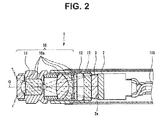
- Fig. 2 is a sectional view of the image pickup unit 1.
- the image pickup unit 1 includes the objective lens unit 10 and the image pickup device 2.
- the objective lens unit 10 includes a plurality of optical elements such as a lens, a filter, and a diaphragm and is configured to form an object image on an image surface.
- the objective lens unit 10 is configured by a plurality of lenses 10a disposed on a linear optical axis O.
- a direction toward a matter side (an object side) along the optical axis O is referred to as front and a direction toward an image side opposite to the object side is referred to as rear.
- the objective lens unit 10 may include an optical element having a reflection surface such as a mirror or a prism.
- the optical axis O may bend on the reflection surface.
- the plurality of lenses 10a are fixed in a cylindrical lens barrel 11.
- a holding frame 12 is fixed to a rear end portion of the lens barrel 11.
- the holding frame 12 is a cylindrical member.
- a front end portion of the holding frame 12 fits in the rear end portion of the lens barrel 11.
- a disk-like optical member 13 fits in an inside of a rear end portion of the holding frame 12. Details of the holding frame 12 and the optical member 13 are explained below.
- the image pickup device 2 is, for example, a CCD, a MOS image sensor, or a CMOS image sensor.
- the image pickup device 2 includes a light receiving surface 2a on which a plurality of pixels including photodiodes are arrayed.
- a cover glass 3 for sealing the light receiving surface 2a is stuck on the light receiving surface 2a of the image pickup device 2.
- the cover glass 3 is also referred to as lid glass or the like.
- a front surface of the cover glass 3 is bonded to a rear surface of the optical member 13 by an adhesive. That is, the image pickup device 2 is fixed to the holding frame 12 via the cover glass 3 and the optical member 13.
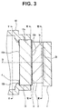
- Fig. 3 is an enlarged sectional view of a portion of the rear end portion of the holding frame 12, the optical member 13, the cover glass 3, and the image pickup device 2 of the image pickup unit 1.
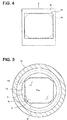
- Fig. 4 is a front view of the light receiving surface 2a of the image pickup device 2.
- Fig. 5 is a V-V sectional view of Fig. 3 .
- Fig. 6 is a VI-VI sectional view of Fig. 3 .
- Fig. 7 is a VII-VII sectional view of Fig. 3 .
- pixel formation region 2b is, for example, rectangular or square.
- the camera control unit 120a generates a video displayed on the image display section 121 using the pixels in a partial region in the pixel formation region 2b rather than generating a video displayed on the image display section 121 using all the pixels of the pixel formation region 2b of the image pickup device 2.
- the region including the pixels used for signal generation for generating the video is defined as display region 2c.
- the display region 2c is octagonal. More specifically, the display region 2c has four outer sides parallel to an external shape of the rectangular or square pixel formation region 2b.
- the display region 2c has a shape obtained by cutting off, with straight lines, four corner portions of a quadrangle shape formed by the four outer sides.
- the image pickup device 2 is disposed such that a center of the display region 2c is located on the optical axis O. In the present embodiment, a center of the pixel formation region 2b and the center of the display region 2c coincide with each other.
- a form may be used in which a driving mode of the image pickup device 2 is set such that the image pickup device 2 outputs only signals from the pixels located in the display region 2c.
- a form may be used in which, after signals outputted form all the pixels of the image pickup device 2 are read out, a video in a region equivalent to the display region 2c may be cutout by image processing.
- the center of the pixel formation region 2b and the center of the display region 2c do not have to coincide with each other.
- An aspect ratio of the pixel formation region 2b and an aspect ratio of the display region 2c do not have to be the same.
- the cover glass 3 is fixed on the light receiving surface 2a of the image pickup device 2.
- the cover glass 3 is a member that seals the pixel formation region 2b.
- the cover glass 3 is a flat plate that is rectangular or square when viewed from a direction parallel to the optical axis O.
- the cover glass 3 has an external shape larger than the pixel formation region 2b when viewed from the direction parallel to the optical axis O.
- the cover glass 3 is disposed such that four outer sides of the cover glass 3 are parallel to an external shape of the pixel formation region 2b and the cover glass 3 covers the entire pixel formation region 2b when viewed from the direction parallel to the optical axis O.
- a center of the cover glass 3 is located on the optical axis O.
- the optical member 13 is fixed on a surface on an opposite side of the image pickup device 2 of the cover glass 3, that is, the front surface of the cover glass 3.
- the optical member 13 is a flat plate made of a transparent material such as glass and circular when viewed from the direction parallel to the optical axis O.
- the disk-like optical member 13 is disposed such that a center is located on the optical axis O.
- a diameter D of the optical member 13 is smaller than a diagonal line length L of the rectangular or square cover glass 3.
- the diameter D of the optical member 13 is set to a value for covering the entire display region 2c with the optical member 13 when viewed from the direction parallel to the optical axis O.
- the diameter D of the circular optical member 13 is set smaller than the diagonal line length L of the rectangular or square cover glass 3. Consequently, it is possible to reduce projection of the optical member 13 from the external shape of the cover glass 3. It is possible to realize a reduction in size of the image pickup unit 1.
- a fitting hole 12a is formed at the rear end portion of the holding frame 12.
- a rear end of the cylindrical holding frame 12 has a shape cut off by a plane orthogonal to the optical axis O.
- the fitting hole 12a is a circular hole centering on the optical axis O.
- the fitting hole 12a has an inner diameter in which the disk-like optical member 13 fits.
- the optical member 13 is inserted from the rear to the front in the fitting hole 12a and fixed by an adhesive.
- a projecting section 12b projecting toward a radial direction inner side of the fitting hole 12a is provided on an inner wall surface of the fitting hole 12a.
- the projecting section 12b is a part for positioning the optical member 13 in the direction parallel to the optical axis O.
- the projecting section 12b is provided over an entire circumferential direction of the inner wall surface of the fitting hole 12a.
- the projecting section 12b is provided at a predetermined distance from the rear end of the holding frame 12 toward the front in parallel to the optical axis O. A distance between the rear end of the holding frame 12 and a rear end of the projecting section 12b is shorter than thickness of the optical member 13.
- a first light blocking member 4 and a second light blocking member 5 are disposed in contact with a front end face 13a of the optical member 13 and a rear end face 13b of the optical member 13.
- the first light blocking member 4 and the second light blocking member 5 are members for blocking visual field external light made incident on the objective lens unit 10 from an outside of a visual field of the image pickup unit 1.
- the visual field external light refers to a ray other than a ray that forms an image in the display region 2c among rays that reach the rear end portion of the holding frame 12 passing through the objective lens unit 10.
- the first light blocking member 4 and the second light blocking member 5 are thin plate-like or thin film-like members made of a material that does not transmit light such as metal or resin.
- the first light blocking member 4 is a thin plate-like member held between the rear end of the projecting section 12b and the front end face 13a of the optical member 13 in the fitting hole 12a.
- the first light blocking member 4 may be a thin film formed on the front end face 13a of the optical member 13 by vapor deposition or the like.
- the first light blocking member 4 includes an opening section 4a, which is a hole through which the optical axis O pierces.
- the opening section 4a has an octagonal shape similar to a shape of the display region 2c when viewed from the direction parallel to the optical axis O and is provided such that respective sides are parallel to respective sides of the display region 2c.
- an external shape of the display region 2c is indicated by an alternate long and two short dashes line. A ray passing through the objective lens unit 10 and forming an image in the display region 2c passes through the opening section 4a.
- the opening section 4a is larger than the display region 2c.
- the opening section 4a may have size same as the size of the display region 2c or may be smaller than the display region 2c.
- the second light blocking member 5 is a thin film made of metal formed on the rear end face 13b of the optical member 13.
- the second light blocking member 5 is formed by, for example, a vapor deposition method.
- the second light blocking member 5 may be a thin plate-like member.
- a shape of the second light blocking member 5 viewed from the direction parallel to the optical axis O is indicated by hatching of half-tone dot meshing.
- the second light blocking member 5 is an outer edge portion of the rear end face 13b of the optical member 13 and is provided in a region where the second light blocking member 5 does not hinder the ray that forms an image in the display region 2c passing through the objective lens unit 10.
- the second light blocking member 5 includes an opening section 5a through which the optical axis O pierces. The ray that forms an image in the display region 2c passing through the objective lens unit 10 passes through the opening section 5a.
- the external shape of the display region 2c is indicated by an alternate long and short dashes line.
- four corner portions of the rectangular or square pixel formation region 2b are indicated by alternate long and short dash lines.
- the second light blocking member 5 includes the opening section 5a having a shape similar to a rectangular or a square shape formed by four outer sides parallel to the external shape of the pixel formation region 2b in the outer sides of the display region 2c. Note that a relation between sizes of the display region 2c and the opening section 5a is appropriately decided according to an angle of the ray that forms an image in the display region 2c passing through the objective lens unit 10. Therefore, in the present embodiment shown in the figure, the opening section 5a is larger than the display region 2c. However, the opening section 5a may have size same as the size of the display region 2c or may be smaller than the display region 2c.
- the second light blocking member 5 includes cutout sections 5b at four corner portions of the opening section 5a.
- the cutout sections 5b are regions where the second light blocking member 5 is not formed and transmit light.
- the cutout sections 5b are provided in regions overlapping the four corner portions of the pixel formation region 2b when viewed from the direction parallel to the optical axis O.
- the optical member 13, the cover glass 3, and the image pickup device 2 are viewed from the front in parallel to the optical axis O, the four corner portions of the pixel formation region 2b are seen through the cutout sections 5b.
- the cutout sections 5b are provided in the regions overlapping the four corner portions of the pixel formation region 2b when viewed from the front of the second light blocking member 5. Consequently, when the rear end face 13b of the optical member 13 on which the second light blocking member 5 is formed and a front end face of the cover glass 3 fixed to the image pickup device 2 are stuck together, it is possible to easily position the rear end face 13b and the front end face on the basis of the external shape of the pixel formation region 2b.
- the image pickup unit 1 in the present embodiment includes, the objective lens unit 10, the rectangular or square cover glass 3 fixed on the light receiving surface 2a, which is the front end face of the image pickup device 2, the circular optical member 13 stuck to the front end face of the cover glass 3 and having a diameter smaller than the diagonal line length of the cover glass 3, the holding frame 12 fixed to the objective lens unit 10, and having a circular fitting hole 12a in which the optical member 13 is fit from a rear, the projecting section 12b projecting toward the radial direction inner side in the holding frame 12, the first light blocking member 4 disposed between the projecting section 12b and the front end face 13a of the optical member 13 to block the visual field external light, and the second light blocking member 5 disposed between the rear end face 13b of the optical member 13 and the cover glass 3 to block the visual field external light.
- Fig. 8 is a diagram showing respective external shapes of the rear end portion of the holding frame 12, the optical member 13, the cover glass 3, and the image pickup device 2 viewed from the front in parallel to the optical axis O.
- a diameter of the circular optical member 13 is smaller than the diagonal line length of the rectangular or square cover glass 3. Therefore, when viewed from the front in parallel to the optical axis O, four corner portions of the cover glass 3 project further toward a radial direction outer side (farther from the optical axis O) than an external shape of the optical member 13. In other parts, when viewed from the front in parallel to the optical axis O, outer sides of the cover glass 3 are located further on a radial direction inner side than the external shape of the optical member 13.
- Fig. 9 is a IX-IX sectional view in Fig. 8 and is a cross section taken along a plane including the optical axis O.
- Fig. 9 shows a part where the cover glass 3 is located further on the radial direction inner side than the external shape of the optical member 13.
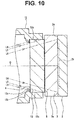
- Fig. 10 is a X-X sectional view in Fig. 8 and is a cross section taken along the plane including the optical axis O.
- Fig. 10 shows a part where the cover glass 3 projects further toward the radial direction outer side than the external shape of the optical member 13.
- the image pickup unit 1 and the endoscope 101 in the present embodiment can achieve both of a reduction in size by a reduction in the diameter of the circular optical member 13 and suppression of flares.
- the projecting section 12b is provided over the entire circumferential direction of the inner wall surface of the fitting hole 12a to form a circular opening for transmitting a ray emitted from the objective lens unit 10.
- the projecting section 12b may form an opening having a shape different from the circular shape.
- an opening 12d formed in the fitting hole 12a by the projecting section 12b has a rectangular shape or a square shape formed by four sides parallel to the external shape of the pixel formation region 2b.
- the rectangular or square opening 12d is inscribed with the inner wall surface of the fitting hole 12a. Therefore, the projecting section 12b is divided in the circumferential direction at four corner portions of the opening 12d. In other words, when viewed from the direction parallel to the optical axis O, portions of the projecting section 12b overlapping vicinities of the four corners of the pixel formation region 2b are cut out.
- a second embodiment of the present invention is explained below. Only differences from the first embodiment are explained below. Components same as the components in the first embodiment are denoted by the same reference numerals and signs. Explanation of the components is omitted as appropriate.
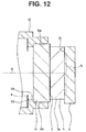
- the image pickup unit 1 in the present embodiment is different from the first embodiment in a disposition part of the first light blocking member 4. As shown in Fig. 12 , the first light blocking member 4 of the present embodiment is in contact with a front end face of a protrusion section 12 and fixed.
- the first light blocking member 4 By disposing the first light blocking member 4 on the front end face of the protrusion section 12 as in the present embodiment, visual field external lights having angles of incidence on the inner wall surface 12c of the protrusion section 12 can be blocked by the first light blocking member 4.
- the first light blocking member 4 blocks parts of visual field external lights having angles of incidence on the side surface 13c of the optical member 13.
- a disposition part of the second light blocking member 5 is the same as the disposition part in the first embodiment. Therefore, the second light blocking member 5 blocks visual field external lights made incident on the side surface 13c of the optical member 13 without being blocked by the first light blocking member 4 and reflecting toward the inside of the display region 2c. Visual field external lights having angles of incidence on the side surface 3a of the cover glass 3 are not made incident on the display region 2c.
- the image pickup unit 1 and the endoscope 101 in the present embodiment can achieve both of a reduction in size by a reduction in the diameter of the circular optical member 13 and suppression of flares.
Landscapes
- Physics & Mathematics (AREA)
- Health & Medical Sciences (AREA)
- Life Sciences & Earth Sciences (AREA)
- Optics & Photonics (AREA)
- Surgery (AREA)
- General Physics & Mathematics (AREA)
- Engineering & Computer Science (AREA)
- Radiology & Medical Imaging (AREA)
- Public Health (AREA)
- Biophysics (AREA)
- Nuclear Medicine, Radiotherapy & Molecular Imaging (AREA)
- Pathology (AREA)
- Veterinary Medicine (AREA)
- General Health & Medical Sciences (AREA)
- Biomedical Technology (AREA)
- Heart & Thoracic Surgery (AREA)
- Medical Informatics (AREA)
- Molecular Biology (AREA)
- Animal Behavior & Ethology (AREA)
- Astronomy & Astrophysics (AREA)
- Multimedia (AREA)
- Signal Processing (AREA)
- Endoscopes (AREA)
- Instruments For Viewing The Inside Of Hollow Bodies (AREA)
- Lens Barrels (AREA)
Abstract
Description
- The present invention relates to an image pickup unit and an endoscope including an objective lens unit and an image pickup device.
- In order to observe a part where it is difficult to observe in-vivo of an organism, an inside of a structure or the like, an endoscope including, in a distal end portion of an insertion section insertable from an outside to the inside of the organism or the structure, an image pickup unit for picking up an optical image is used in, for example, a medical field and an industrial field.
- For example, as disclosed in Japanese Patent Application Laid-Open Publication No.
H10-146312 - In the image pickup unit of the endoscope, for example, as shown in
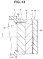
Fig. 13 , acover glass 23 for sealing alight receiving surface 22a is fixed on alight receiving surface 22a of animage pickup device 22. Anoptical member 24 made of a transparent member such as glass is stuck to a front surface of thecover glass 23. - The
optical member 24 is fit in afitting hole 21a formed in aholding frame 21 fixed to a not-shown objective lens unit and is fixed by an adhesive or the like. In this way, some image pickup units include a configuration in which theimage pickup device 22 is fixed to, via theoptical member 24, theholding frame 21 fixed to the objective lens unit. - In the image pickup unit including the
optical member 24 fit in a rear end of theholding frame 21 fixed to the objective lens unit and theimage pickup device 22 fixed to theoptical member 24 as shown inFig. 13 , it is necessary to reduce an external shape of theoptical member 24 in order to realize a reduction in size (a reduction in diameter) of the image pickup unit. If the external shape of theoptical member 24 is reduced, it is possible to reduce an external shape of a rear end portion of theholding frame 21 as well. - However, when the external shape of the
optical member 24 disposed in a front of theimage pickup device 22 is reduced, side surfaces of theoptical member 24 are close to an optical axis. Therefore, as shown as a line segment L10 of an alternate long and two short dashes line inFig. 13 , a ray reflected on the side surface of theoptical member 24 is made incident on apixel formation region 22b of theimage pickup device 22 and causes flares. - Therefore, as shown in
Fig. 14 , if alight blocking member 25 is disposed on a surface (a surface on an image side) behind theoptical member 24, the ray L10 reflected on the side surface of theoptical member 24 can be blocked. However, in this case, a ray L11 reflected on aprotrusion section 21b for bumping theoptical member 24 provided in theholding frame 21 is made incident on thepixel formation region 22b of theimage pickup device 22 and causes flares. - As shown in
Fig. 15 , if the external shape of theoptical member 24 is set the same as thecover glass 23 or larger than thecover glass 23, the side surface of theoptical member 24 and a part against which theoptical member 24 of theholding frame 21 is bumped can be provided away from the optical axis. Therefore, it is possible to prevent occurrence of flares due to the rays reflected on these parts. However, in this case, the image pickup unit is increased in size (increased in diameter) as explained above. - The present invention has been devised in view of the points explained above and it is an object of the present invention to provide an image pickup unit and an endoscope that achieve both of a reduction in size and suppression of flares.
- An image pickup unit according to an aspect of the present invention includes: an objective lens unit; a rectangular or square cover glass fixed on a light receiving surface, which is a front end face of an image pickup device; a circular optical member stuck to a front end face of the cover glass and having a diameter smaller than a diagonal line length of the cover glass; a holding frame fixed to the objective lens unit, and having a circular fitting hole in which the optical member is fit from a rear; a projecting section projecting toward a radial direction inner side in the holding frame; a first light blocking member disposed in a front of the optical member to block visual field external light reflecting on an inner wall surface of the projecting section and traveling to an inside of a pixel formation region of the image pickup device; and a second light blocking member disposed between a rear end face of the optical member and a front end face of the cover glass to block the visual field external light reflecting on a side surface of the optical member and having an angle toward the inside of the pixel formation region. An endoscope according to an aspect of the present invention includes the image pickup unit.
-
-
Fig. 1 is a diagram for explaining a configuration of an endoscope; -
Fig. 2 is a sectional view of an image pickup unit; -
Fig. 3 is an enlarged sectional view of a rear end portion of a holding frame, an optical member, a cover glass, and an image pickup device; -
Fig. 4 is a front view of a light receiving surface of the image pickup device; -
Fig. 5 is a V-V sectional view ofFig. 3 ; -
Fig. 6 is a VI-VI sectional view ofFig. 3 ; -
Fig. 7 is a VII-VII sectional view ofFig. 3 ; -
Fig. 8 is a diagram showing respective external shapes of the rear end portion of the holding frame, the optical member, the cover glass, and the image pickup device viewed from a front; -
Fig. 9 is a IX-IX sectional view ofFig. 8 ; -
Fig. 10 is a X-X sectional view ofFig. 8 ; -
Fig. 11 is a diagram showing a modification of a protrusion section; -
Fig. 12 is a sectional view of an image pickup unit of a second embodiment; -
Fig. 13 is a sectional view for explaining a conventional image pickup unit; -
Fig. 14 is a sectional view for explaining the conventional image pickup unit; and -
Fig. 15 is a sectional view for explaining the conventional image pickup unit. - A preferred mode of the present invention is explained below with reference to the drawings. Note that, in respective figures used in the following explanation, scales are differentiated for each of components in order to show the respective components in sizes recognizable on the drawings. The present invention is not limited to only quantities of the components, shapes of the components, ratios of sizes of the components, and a relative positional relation among the components described in the figures.
- An example of an embodiment of the present invention is explained below. First, an example of a configuration of an
endoscope 101 according to the present invention is explained with reference toFig. 1 . Theendoscope 101 in the present embodiment includes a configuration introducible into a subject such as a human body and capable of optically picking up an image of a predetermined observation part in the subject. Note that the object into which theendoscope 101 is introduced is not limited to the human body and may be other organisms or may be an artificial object such as a machine or a structure. - The
endoscope 101 in the present embodiment is mainly configured by anelongated insertion section 102 introduced into an inside of the object, anoperation section 103 located at a proximal end of theinsertion section 102, and auniversal cord 104 extending from a side portion of theoperation section 103. - The
insertion section 102 is configured by concatenating adistal end portion 110 disposed at a distal end, abendable bending section 109 disposed on a proximal end side of thedistal end portion 110, and aflexible tube section 108 having flexibility disposed on a proximal end side of thebending section 109 and connected to a distal end side of theoperation section 103. Animage pickup unit 1 including anobjective lens unit 10 and animage pickup device 2 is disposed at thedistal end portion 110. Although not shown in the figure, an illumination-light emitting section that emits light for illuminating an object of theimage pickup unit 1 is also provided at thedistal end portion 110. Note that theendoscope 101 may be an endoscope of a form called rigid endoscope not including a part having flexibility in an insertion section. - In the
operation section 103 disposed at a proximal end of theinsertion section 102, anangle operation knob 106 for operating bending of thebending section 109 is provided. Anendoscope connector 105 configured to be connectable to anexternal apparatus 120 is provided at a proximal end portion of theuniversal cord 104. Theexternal apparatus 120, to which theendoscope connector 105 is connected, includes acamera control unit 120a. - In the
endoscope 101, atransmission cable 115 inserted through theinsertion section 102, theoperation section 103, and theuniversal cord 104 is disposed. Thetransmission cable 115 is configured to electrically connect theimage pickup unit 1 and theconnector portion 105. Theconnector portion 105 is connected to theexternal apparatus 120, whereby theimage pickup unit 1 is electrically connected to thecamera control unit 120a of theexternal apparatus 120 via thetransmission cable 115. Supply of electric power from theexternal apparatus 120 to theimage pickup unit 1 and exchange of signals between theexternal apparatus 120 and theimage pickup unit 1 are performed via thetransmission cable 115. - The
camera control unit 120a includes a configuration for generating a video based on a signal outputted from theimage pickup unit 1 and outputting the video to animage display section 121. That is, in the present embodiment, an optical image picked up by theimage pickup unit 1 is displayed on theimage display section 121 as a video. Note that a part or all of thecamera control unit 120a and theimage display section 121 may be configured integrally with theendoscope 101. - A detailed configuration of the
image pickup unit 1 is explained.Fig. 2 is a sectional view of theimage pickup unit 1. Theimage pickup unit 1 includes theobjective lens unit 10 and theimage pickup device 2. - The
objective lens unit 10 includes a plurality of optical elements such as a lens, a filter, and a diaphragm and is configured to form an object image on an image surface. In the present embodiment, as an example, theobjective lens unit 10 is configured by a plurality oflenses 10a disposed on a linear optical axis O. In the following explanation, a direction toward a matter side (an object side) along the optical axis O is referred to as front and a direction toward an image side opposite to the object side is referred to as rear. Note that theobjective lens unit 10 may include an optical element having a reflection surface such as a mirror or a prism. The optical axis O may bend on the reflection surface. - The plurality of
lenses 10a are fixed in acylindrical lens barrel 11. A holdingframe 12 is fixed to a rear end portion of thelens barrel 11. The holdingframe 12 is a cylindrical member. A front end portion of the holdingframe 12 fits in the rear end portion of thelens barrel 11. A disk-likeoptical member 13 fits in an inside of a rear end portion of the holdingframe 12. Details of the holdingframe 12 and theoptical member 13 are explained below. - The
image pickup device 2 is, for example, a CCD, a MOS image sensor, or a CMOS image sensor. Theimage pickup device 2 includes alight receiving surface 2a on which a plurality of pixels including photodiodes are arrayed. - A
cover glass 3 for sealing thelight receiving surface 2a is stuck on thelight receiving surface 2a of theimage pickup device 2. Thecover glass 3 is also referred to as lid glass or the like. A front surface of thecover glass 3 is bonded to a rear surface of theoptical member 13 by an adhesive. That is, theimage pickup device 2 is fixed to the holdingframe 12 via thecover glass 3 and theoptical member 13. -
Fig. 3 is an enlarged sectional view of a portion of the rear end portion of the holdingframe 12, theoptical member 13, thecover glass 3, and theimage pickup device 2 of theimage pickup unit 1.Fig. 4 is a front view of thelight receiving surface 2a of theimage pickup device 2.Fig. 5 is a V-V sectional view ofFig. 3 .Fig. 6 is a VI-VI sectional view ofFig. 3 .Fig. 7 is a VII-VII sectional view ofFig. 3 . - As shown in
Fig. 4 , on thelight receiving surface 2a of theimage pickup device 2, all the pixels are formed in apixel formation region 2b in a predetermined array. Thepixel formation region 2b is, for example, rectangular or square. - In the present embodiment, the
camera control unit 120a generates a video displayed on theimage display section 121 using the pixels in a partial region in thepixel formation region 2b rather than generating a video displayed on theimage display section 121 using all the pixels of thepixel formation region 2b of theimage pickup device 2. The region including the pixels used for signal generation for generating the video is defined asdisplay region 2c. - In the present embodiment, as an example, the
display region 2c is octagonal. More specifically, thedisplay region 2c has four outer sides parallel to an external shape of the rectangular or squarepixel formation region 2b. Thedisplay region 2c has a shape obtained by cutting off, with straight lines, four corner portions of a quadrangle shape formed by the four outer sides. Theimage pickup device 2 is disposed such that a center of thedisplay region 2c is located on the optical axis O. In the present embodiment, a center of thepixel formation region 2b and the center of thedisplay region 2c coincide with each other. - Note that, in converting an optical image formed in the
display region 2c into a video displayed on theimage display section 121, a form may be used in which a driving mode of theimage pickup device 2 is set such that theimage pickup device 2 outputs only signals from the pixels located in thedisplay region 2c. Alternatively, a form may be used in which, after signals outputted form all the pixels of theimage pickup device 2 are read out, a video in a region equivalent to thedisplay region 2c may be cutout by image processing. The center of thepixel formation region 2b and the center of thedisplay region 2c do not have to coincide with each other. An aspect ratio of thepixel formation region 2b and an aspect ratio of thedisplay region 2c do not have to be the same. - As shown in
Fig. 3 andFig. 7 , thecover glass 3 is fixed on thelight receiving surface 2a of theimage pickup device 2. Thecover glass 3 is a member that seals thepixel formation region 2b. Thecover glass 3 is a flat plate that is rectangular or square when viewed from a direction parallel to the optical axis O. Thecover glass 3 has an external shape larger than thepixel formation region 2b when viewed from the direction parallel to the optical axis O. - As shown in
Fig. 7 , thecover glass 3 is disposed such that four outer sides of thecover glass 3 are parallel to an external shape of thepixel formation region 2b and thecover glass 3 covers the entirepixel formation region 2b when viewed from the direction parallel to the optical axis O. A center of thecover glass 3 is located on the optical axis O. - As shown in
Fig. 3 andFig. 6 , theoptical member 13 is fixed on a surface on an opposite side of theimage pickup device 2 of thecover glass 3, that is, the front surface of thecover glass 3. Theoptical member 13 is a flat plate made of a transparent material such as glass and circular when viewed from the direction parallel to the optical axis O. The disk-likeoptical member 13 is disposed such that a center is located on the optical axis O. - As shown in
Fig. 6 , a diameter D of theoptical member 13 is smaller than a diagonal line length L of the rectangular orsquare cover glass 3. The diameter D of theoptical member 13 is set to a value for covering theentire display region 2c with theoptical member 13 when viewed from the direction parallel to the optical axis O. In this way, the diameter D of the circularoptical member 13 is set smaller than the diagonal line length L of the rectangular orsquare cover glass 3. Consequently, it is possible to reduce projection of theoptical member 13 from the external shape of thecover glass 3. It is possible to realize a reduction in size of theimage pickup unit 1. - As shown in
Fig. 3 andFig. 5 , afitting hole 12a is formed at the rear end portion of the holdingframe 12. A rear end of thecylindrical holding frame 12 has a shape cut off by a plane orthogonal to the optical axis O. - The
fitting hole 12a is a circular hole centering on the optical axis O. Thefitting hole 12a has an inner diameter in which the disk-likeoptical member 13 fits. Theoptical member 13 is inserted from the rear to the front in thefitting hole 12a and fixed by an adhesive. - A projecting
section 12b projecting toward a radial direction inner side of thefitting hole 12a is provided on an inner wall surface of thefitting hole 12a. The projectingsection 12b is a part for positioning theoptical member 13 in the direction parallel to the optical axis O. In the present embodiment, as shown inFig. 5 , the projectingsection 12b is provided over an entire circumferential direction of the inner wall surface of thefitting hole 12a. - The projecting
section 12b is provided at a predetermined distance from the rear end of the holdingframe 12 toward the front in parallel to the optical axis O. A distance between the rear end of the holdingframe 12 and a rear end of the projectingsection 12b is shorter than thickness of theoptical member 13. - In the
image pickup unit 1 in the present embodiment, as shown inFig. 3 , a firstlight blocking member 4 and a secondlight blocking member 5 are disposed in contact with afront end face 13a of theoptical member 13 and arear end face 13b of theoptical member 13. - The first
light blocking member 4 and the secondlight blocking member 5 are members for blocking visual field external light made incident on theobjective lens unit 10 from an outside of a visual field of theimage pickup unit 1. The visual field external light refers to a ray other than a ray that forms an image in thedisplay region 2c among rays that reach the rear end portion of the holdingframe 12 passing through theobjective lens unit 10. The firstlight blocking member 4 and the secondlight blocking member 5 are thin plate-like or thin film-like members made of a material that does not transmit light such as metal or resin. - In the present embodiment, as an example, the first
light blocking member 4 is a thin plate-like member held between the rear end of the projectingsection 12b and thefront end face 13a of theoptical member 13 in thefitting hole 12a. Note that the firstlight blocking member 4 may be a thin film formed on thefront end face 13a of theoptical member 13 by vapor deposition or the like. - As shown in
Fig. 5 , the firstlight blocking member 4 includes anopening section 4a, which is a hole through which the optical axis O pierces. Theopening section 4a has an octagonal shape similar to a shape of thedisplay region 2c when viewed from the direction parallel to the optical axis O and is provided such that respective sides are parallel to respective sides of thedisplay region 2c. InFig. 5 , an external shape of thedisplay region 2c is indicated by an alternate long and two short dashes line. A ray passing through theobjective lens unit 10 and forming an image in thedisplay region 2c passes through theopening section 4a. - Note that a relation between sizes of the
display region 2c and theopening section 4a is appropriately decided according to an angle of the ray that forms an image in thedisplay region 2c passing through theobjective lens unit 10. Therefore, in the present embodiment shown in the figure, theopening section 4a is larger than thedisplay region 2c. However, theopening section 4a may have size same as the size of thedisplay region 2c or may be smaller than thedisplay region 2c. - In the present embodiment, as an example, the second
light blocking member 5 is a thin film made of metal formed on therear end face 13b of theoptical member 13. The secondlight blocking member 5 is formed by, for example, a vapor deposition method. Note that the secondlight blocking member 5 may be a thin plate-like member. - In
Fig. 6 , a shape of the secondlight blocking member 5 viewed from the direction parallel to the optical axis O is indicated by hatching of half-tone dot meshing. - As shown in
Fig. 6 , the secondlight blocking member 5 is an outer edge portion of therear end face 13b of theoptical member 13 and is provided in a region where the secondlight blocking member 5 does not hinder the ray that forms an image in thedisplay region 2c passing through theobjective lens unit 10. In other word, the secondlight blocking member 5 includes anopening section 5a through which the optical axis O pierces. The ray that forms an image in thedisplay region 2c passing through theobjective lens unit 10 passes through theopening section 5a. - Note that, in
Fig. 6 , the external shape of thedisplay region 2c is indicated by an alternate long and short dashes line. InFig. 6 , four corner portions of the rectangular or squarepixel formation region 2b are indicated by alternate long and short dash lines. - The second
light blocking member 5 includes theopening section 5a having a shape similar to a rectangular or a square shape formed by four outer sides parallel to the external shape of thepixel formation region 2b in the outer sides of thedisplay region 2c. Note that a relation between sizes of thedisplay region 2c and theopening section 5a is appropriately decided according to an angle of the ray that forms an image in thedisplay region 2c passing through theobjective lens unit 10. Therefore, in the present embodiment shown in the figure, theopening section 5a is larger than thedisplay region 2c. However, theopening section 5a may have size same as the size of thedisplay region 2c or may be smaller than thedisplay region 2c. - In the present embodiment, as shown in
Fig. 6 , the secondlight blocking member 5 includescutout sections 5b at four corner portions of theopening section 5a. Thecutout sections 5b are regions where the secondlight blocking member 5 is not formed and transmit light. Thecutout sections 5b are provided in regions overlapping the four corner portions of thepixel formation region 2b when viewed from the direction parallel to the optical axis O. - That is, when the
optical member 13, thecover glass 3, and theimage pickup device 2 are viewed from the front in parallel to the optical axis O, the four corner portions of thepixel formation region 2b are seen through thecutout sections 5b. In this way, thecutout sections 5b are provided in the regions overlapping the four corner portions of thepixel formation region 2b when viewed from the front of the secondlight blocking member 5. Consequently, when therear end face 13b of theoptical member 13 on which the secondlight blocking member 5 is formed and a front end face of thecover glass 3 fixed to theimage pickup device 2 are stuck together, it is possible to easily position therear end face 13b and the front end face on the basis of the external shape of thepixel formation region 2b. - As explained above, the
image pickup unit 1 in the present embodiment includes, theobjective lens unit 10, the rectangular orsquare cover glass 3 fixed on thelight receiving surface 2a, which is the front end face of theimage pickup device 2, the circularoptical member 13 stuck to the front end face of thecover glass 3 and having a diameter smaller than the diagonal line length of thecover glass 3, the holdingframe 12 fixed to theobjective lens unit 10, and having a circularfitting hole 12a in which theoptical member 13 is fit from a rear, the projectingsection 12b projecting toward the radial direction inner side in the holdingframe 12, the firstlight blocking member 4 disposed between the projectingsection 12b and thefront end face 13a of theoptical member 13 to block the visual field external light, and the secondlight blocking member 5 disposed between therear end face 13b of theoptical member 13 and thecover glass 3 to block the visual field external light. - Action of the first
light blocking member 4 and the secondlight blocking member 5 is explained below.Fig. 8 is a diagram showing respective external shapes of the rear end portion of the holdingframe 12, theoptical member 13, thecover glass 3, and theimage pickup device 2 viewed from the front in parallel to the optical axis O. - In the
image pickup unit 1 in the present embodiment, a diameter of the circularoptical member 13 is smaller than the diagonal line length of the rectangular orsquare cover glass 3. Therefore, when viewed from the front in parallel to the optical axis O, four corner portions of thecover glass 3 project further toward a radial direction outer side (farther from the optical axis O) than an external shape of theoptical member 13. In other parts, when viewed from the front in parallel to the optical axis O, outer sides of thecover glass 3 are located further on a radial direction inner side than the external shape of theoptical member 13. -
Fig. 9 is a IX-IX sectional view inFig. 8 and is a cross section taken along a plane including the optical axis O.Fig. 9 shows a part where thecover glass 3 is located further on the radial direction inner side than the external shape of theoptical member 13.Fig. 10 is a X-X sectional view inFig. 8 and is a cross section taken along the plane including the optical axis O.Fig. 10 shows a part where thecover glass 3 projects further toward the radial direction outer side than the external shape of theoptical member 13. - In order to block harmful lights such as flares adversely affecting an image in the
image pickup unit 1, among visual field external lights that reach the rear end portion of the holdingframe 12 passing through theobjective lens unit 10, it is necessary to block light reflecting on aninner wall surface 12c of the projectingsection 12b, aside surface 13c of theoptical member 13, and aside surface 3a of thecover glass 3 and reaching thedisplay region 2c. - In the present embodiment, as shown as line segments L1 and L4 of alternate long and short two dashes lines in
Fig. 9 andFig. 10 , visual field external lights reflecting toward the inside of thedisplay region 2c on theinner wall surface 12c of the projectingsection 12b are blocked by the firstlight blocking member 4 disposed in the front of theoptical member 13. - As shown as line segments L2 and L5 of alternate long and two short dashes lines in
Fig. 9 andFig. 10 , parts of visual field external lights having angles of incidence on theside surface 13c of theoptical member 13 are blocked by the firstlight blocking member 4. Visual field external lights made incident on theside surface 13c of theoptical member 13 without being blocked by the firstlight blocking member 4 and reflecting toward the inside of thedisplay region 2c are blocked by the secondlight blocking member 5 disposed in the rear of theoptical member 13. - As shown as line segments L3 and L6 of alternate long and two short dashes lines in
Fig. 9 andFig. 10 , visual field external lights having angles of incidence on theside surface 3a of thecover glass 3 are not made incident on thedisplay region 2c. - As explained above, in the present embodiment, among the visual field external lights that reaches the rear end portion of the holding
frame 12 passing through theobjective lens unit 10, all harmful lights such as flares adversely affecting an image can be blocked by the firstlight blocking member 4 and the secondlight blocking member 5. - As explained above, the
image pickup unit 1 and theendoscope 101 in the present embodiment can achieve both of a reduction in size by a reduction in the diameter of the circularoptical member 13 and suppression of flares. - Note that, in the present embodiment explained above, the projecting
section 12b is provided over the entire circumferential direction of the inner wall surface of thefitting hole 12a to form a circular opening for transmitting a ray emitted from theobjective lens unit 10. However, as shown as a modification inFig. 11 , the projectingsection 12b may form an opening having a shape different from the circular shape. - In the modification shown in
Fig. 11 , anopening 12d formed in thefitting hole 12a by the projectingsection 12b has a rectangular shape or a square shape formed by four sides parallel to the external shape of thepixel formation region 2b. The rectangular orsquare opening 12d is inscribed with the inner wall surface of thefitting hole 12a. Therefore, the projectingsection 12b is divided in the circumferential direction at four corner portions of theopening 12d. In other words, when viewed from the direction parallel to the optical axis O, portions of the projectingsection 12b overlapping vicinities of the four corners of thepixel formation region 2b are cut out. - In such a modification, at the four corner portions of the
pixel formation regions 2b, which are positions with large image height, it is possible to prevent occurrence of flares due to visual field external lights reflected on theinner wall surface 12c of the projectingsection 12b. - A second embodiment of the present invention is explained below. Only differences from the first embodiment are explained below. Components same as the components in the first embodiment are denoted by the same reference numerals and signs. Explanation of the components is omitted as appropriate.
- The
image pickup unit 1 in the present embodiment is different from the first embodiment in a disposition part of the firstlight blocking member 4. As shown inFig. 12 , the firstlight blocking member 4 of the present embodiment is in contact with a front end face of aprotrusion section 12 and fixed. - By disposing the first
light blocking member 4 on the front end face of theprotrusion section 12 as in the present embodiment, visual field external lights having angles of incidence on theinner wall surface 12c of theprotrusion section 12 can be blocked by the firstlight blocking member 4. - As in the first embodiment, the first
light blocking member 4 blocks parts of visual field external lights having angles of incidence on theside surface 13c of theoptical member 13. A disposition part of the secondlight blocking member 5 is the same as the disposition part in the first embodiment. Therefore, the secondlight blocking member 5 blocks visual field external lights made incident on theside surface 13c of theoptical member 13 without being blocked by the firstlight blocking member 4 and reflecting toward the inside of thedisplay region 2c. Visual field external lights having angles of incidence on theside surface 3a of thecover glass 3 are not made incident on thedisplay region 2c. - As explained above, in the present embodiment, as in the first embodiment, among the visual field external lights that reaches the rear end portion of the holding
frame 12 passing through theobjective lens unit 10, all harmful lights such as flares adversely affecting an image can be blocked by the firstlight blocking member 4 and the secondlight blocking member 5. - Therefore, the
image pickup unit 1 and theendoscope 101 in the present embodiment can achieve both of a reduction in size by a reduction in the diameter of the circularoptical member 13 and suppression of flares. - The present invention is not limited to the embodiments explained above and can be changed as appropriate in a range not departing from the spirit or the idea of the invention read from claims and the entire specification. Image pickup units and endoscopes involving such changes are also included in the technical scope of the present invention.
- This application is based upon and claims priority from Japanese Patent Application No.
2014-105495
Claims (3)
- An image pickup unit comprising:an objective lens unit;a rectangular or square cover glass fixed on a light receiving surface, which is a front end face of an image pickup device;a circular optical member stuck to a front end face of the cover glass and having a diameter smaller than a diagonal line length of the cover glass;a holding frame fixed to the objective lens unit, and having a circular fitting hole in which the optical member is fit from a rear;a projecting section projecting toward a radial direction inner side in the holding frame;a first light blocking member disposed in a front of the optical member to block visual field external light reflecting on an inner wall surface of the projecting section and traveling to an inside of a pixel formation region of the image pickup device; anda second light blocking member disposed between a rear end face of the optical member and a front end face of the cover glass to block the visual field external light reflecting on a side surface of the optical member and having an angle toward the inside of the pixel formation region.
- The image pickup unit according to claim 1, wherein the second light blocking member is made of a thin film vapor-deposited on the rear end face of the optical member.
- An endoscope comprising the image pickup unit according to claim 1 or 2.
Applications Claiming Priority (2)
| Application Number | Priority Date | Filing Date | Title |
|---|---|---|---|
| JP2014105495 | 2014-05-21 | ||
| PCT/JP2015/061636 WO2015178134A1 (en) | 2014-05-21 | 2015-04-15 | Image capturing unit and endoscope |
Publications (4)
| Publication Number | Publication Date |
|---|---|
| EP3061384A1 true EP3061384A1 (en) | 2016-08-31 |
| EP3061384A4 EP3061384A4 (en) | 2017-09-06 |
| EP3061384B1 EP3061384B1 (en) | 2018-06-27 |
| EP3061384B8 EP3061384B8 (en) | 2018-08-08 |
Family
ID=54553810
Family Applications (1)
| Application Number | Title | Priority Date | Filing Date |
|---|---|---|---|
| EP15796750.6A Not-in-force EP3061384B8 (en) | 2014-05-21 | 2015-04-15 | Image pickup unit and endoscope |
Country Status (5)
| Country | Link |
|---|---|
| US (1) | US10067333B2 (en) |
| EP (1) | EP3061384B8 (en) |
| JP (1) | JP5897235B1 (en) |
| CN (1) | CN105744877B (en) |
| WO (1) | WO2015178134A1 (en) |
Cited By (1)
| Publication number | Priority date | Publication date | Assignee | Title |
|---|---|---|---|---|
| EP4149103A1 (en) * | 2021-09-08 | 2023-03-15 | Robert Bosch GmbH | Imaging apparatus with athermal mounting |
Families Citing this family (10)
| Publication number | Priority date | Publication date | Assignee | Title |
|---|---|---|---|---|
| US11782256B2 (en) * | 2016-09-21 | 2023-10-10 | Omnivision Technologies, Inc. | Endoscope imager and associated method |
| JP2018146878A (en) * | 2017-03-08 | 2018-09-20 | カンタツ株式会社 | Lens element and image capturing lens unit |
| WO2018211652A1 (en) * | 2017-05-18 | 2018-11-22 | オリンパス株式会社 | Imaging device and endoscope |
| JP7088730B2 (en) * | 2018-04-25 | 2022-06-21 | オリンパス株式会社 | Endoscope device |
| US11690497B2 (en) * | 2018-11-27 | 2023-07-04 | Fujikura Ltd. | Lens unit |
| JP7078560B2 (en) * | 2019-01-25 | 2022-05-31 | ファナック株式会社 | Precision machine tools |
| TWI737978B (en) * | 2019-03-29 | 2021-09-01 | 大立光電股份有限公司 | Imaging lens module and electronic device |
| TWI776188B (en) * | 2019-07-19 | 2022-09-01 | 日商凸版印刷股份有限公司 | Shading member, lens unit, camera module, and electronic equipment |
| CN116157763A (en) * | 2020-07-21 | 2023-05-23 | 三星电子株式会社 | Electronic devices including displays and camera devices |
| CN113288012A (en) * | 2021-04-30 | 2021-08-24 | 上海澳华内镜股份有限公司 | Endoscope camera device |
Family Cites Families (20)
| Publication number | Priority date | Publication date | Assignee | Title |
|---|---|---|---|---|
| JP3017245B2 (en) * | 1989-09-22 | 2000-03-06 | オリンパス光学工業株式会社 | Endoscope |
| JP3698839B2 (en) | 1996-11-18 | 2005-09-21 | オリンパス株式会社 | Endoscope device |
| JP4245800B2 (en) * | 1997-08-01 | 2009-04-02 | オリンパス株式会社 | Endoscope objective lens |
| JP4503956B2 (en) * | 2003-08-22 | 2010-07-14 | オリンパス株式会社 | Imaging device |
| JP4578913B2 (en) * | 2004-09-28 | 2010-11-10 | オリンパス株式会社 | Imaging device |
| JP5019830B2 (en) * | 2006-09-20 | 2012-09-05 | オリンパスメディカルシステムズ株式会社 | Imaging unit and endoscope to which the imaging unit is applied |
| JP2008219854A (en) * | 2007-02-05 | 2008-09-18 | Matsushita Electric Ind Co Ltd | OPTICAL DEVICE, OPTICAL DEVICE WAFER, MANUFACTURING METHOD THEREOF, AND CAMERA MODULE AND ENDOSCOPE MODULE MOUNTING OPTICAL DEVICE |
| JP4642810B2 (en) * | 2007-05-21 | 2011-03-02 | オリンパス株式会社 | Endoscopic imaging device |
| JP5380690B2 (en) * | 2008-01-08 | 2014-01-08 | オリンパスメディカルシステムズ株式会社 | Endoscope objective optical system and endoscope system using the same |
| JP5154981B2 (en) * | 2008-03-10 | 2013-02-27 | オリンパスイメージング株式会社 | Image pickup apparatus having a zoom lens |
| JP2009244529A (en) * | 2008-03-31 | 2009-10-22 | Konica Minolta Opto Inc | Light shielding part and lens barrel |
| JP5289870B2 (en) * | 2008-09-08 | 2013-09-11 | オリンパスメディカルシステムズ株式会社 | Endoscope imaging unit |
| JP5779314B2 (en) * | 2009-08-20 | 2015-09-16 | Hoya株式会社 | Endoscope device |
| WO2011024573A1 (en) * | 2009-08-31 | 2011-03-03 | オリンパスメディカルシステムズ株式会社 | Imaging device |
| JP5155494B2 (en) * | 2010-11-09 | 2013-03-06 | オリンパスメディカルシステムズ株式会社 | Endoscopic imaging device |
| WO2012086263A1 (en) * | 2010-12-22 | 2012-06-28 | コニカミノルタオプト株式会社 | Image pickup lens |
| JP2013174670A (en) * | 2012-02-23 | 2013-09-05 | Olympus Corp | Lens unit |
| JP5450704B2 (en) * | 2012-03-26 | 2014-03-26 | 株式会社フジクラ | Electrical cable and imaging mechanism with external cylinder, endoscope, electrical cable and method of manufacturing imaging mechanism with external cylinder |
| CN103687530B (en) * | 2012-04-25 | 2016-05-04 | 奥林巴斯株式会社 | Camera unit for endoscope and endoscope |
| JP5933393B2 (en) * | 2012-08-20 | 2016-06-08 | オリンパス株式会社 | Optical unit and endoscope |
-
2015
- 2015-04-15 CN CN201580002657.4A patent/CN105744877B/en active Active
- 2015-04-15 JP JP2015550107A patent/JP5897235B1/en active Active
- 2015-04-15 EP EP15796750.6A patent/EP3061384B8/en not_active Not-in-force
- 2015-04-15 WO PCT/JP2015/061636 patent/WO2015178134A1/en not_active Ceased
-
2016
- 2016-05-19 US US15/158,752 patent/US10067333B2/en active Active
Cited By (1)
| Publication number | Priority date | Publication date | Assignee | Title |
|---|---|---|---|---|
| EP4149103A1 (en) * | 2021-09-08 | 2023-03-15 | Robert Bosch GmbH | Imaging apparatus with athermal mounting |
Also Published As
| Publication number | Publication date |
|---|---|
| CN105744877A (en) | 2016-07-06 |
| JPWO2015178134A1 (en) | 2017-04-20 |
| EP3061384B8 (en) | 2018-08-08 |
| CN105744877B (en) | 2017-11-21 |
| US10067333B2 (en) | 2018-09-04 |
| WO2015178134A1 (en) | 2015-11-26 |
| EP3061384A4 (en) | 2017-09-06 |
| US20160266373A1 (en) | 2016-09-15 |
| JP5897235B1 (en) | 2016-03-30 |
| EP3061384B1 (en) | 2018-06-27 |
Similar Documents
| Publication | Publication Date | Title |
|---|---|---|
| EP3061384B1 (en) | Image pickup until and endoscope | |
| US6483535B1 (en) | Wide angle lens system for electronic imagers having long exit pupil distances | |
| EP1741380B1 (en) | Endoscope system | |
| JP4516475B2 (en) | Imaging optical system for an endoscope having a substantially spherical observation window | |
| EP2929830B1 (en) | Endoscope apparatus | |
| US20170245734A1 (en) | Resin distal end component for endoscope | |
| US8419616B2 (en) | Image pickup device with a protection member and an optical reflection member | |
| US9148554B2 (en) | Image pickup unit for endoscope and endoscope | |
| US10542874B2 (en) | Imaging device and endoscope device | |
| JP4668831B2 (en) | Endoscope | |
| JP5343066B2 (en) | Endoscope device | |
| US11042021B2 (en) | Image pickup apparatus and endoscope apparatus | |
| WO2016121160A1 (en) | Endoscope | |
| EP2570072B1 (en) | Method for assembling endoscopic imaging unit and endoscope | |
| WO2009150653A1 (en) | Optical system for use in an endoscope | |
| US20180045948A1 (en) | Stereo image pickup unit | |
| JP5189762B2 (en) | In vivo imaging optical device | |
| US10602041B2 (en) | Image capturing device | |
| US9661997B2 (en) | Endoscope having image sensor with segmentation region, for outputting video, shifted from center of pixel formation region | |
| CN121285324A (en) | 3D video endoscope | |
| JP2013094259A (en) | Endoscope | |
| US20200333580A1 (en) | Image pickup optical system, endoscope, and image pickup apparatus | |
| JP6415129B2 (en) | Imaging device | |
| US20210085166A1 (en) | Endoscope | |
| US20220061649A1 (en) | Optical instrument and method for producing an optical device |
Legal Events
| Date | Code | Title | Description |
|---|---|---|---|
| PUAI | Public reference made under article 153(3) epc to a published international application that has entered the european phase |
Free format text: ORIGINAL CODE: 0009012 |
|
| 17P | Request for examination filed |
Effective date: 20160518 |
|
| AK | Designated contracting states |
Kind code of ref document: A1 Designated state(s): AL AT BE BG CH CY CZ DE DK EE ES FI FR GB GR HR HU IE IS IT LI LT LU LV MC MK MT NL NO PL PT RO RS SE SI SK SM TR |
|
| AX | Request for extension of the european patent |
Extension state: BA ME |
|
| RAP1 | Party data changed (applicant data changed or rights of an application transferred) |
Owner name: OLYMPUS CORPORATION |
|
| RAP1 | Party data changed (applicant data changed or rights of an application transferred) |
Owner name: OLYMPUS CORPORATION |
|
| RAP1 | Party data changed (applicant data changed or rights of an application transferred) |
Owner name: OLYMPUS CORPORATION |
|
| RIN1 | Information on inventor provided before grant (corrected) |
Inventor name: SAKAI, SEIJI |
|
| DAV | Request for validation of the european patent (deleted) | ||
| DAX | Request for extension of the european patent (deleted) | ||
| A4 | Supplementary search report drawn up and despatched |
Effective date: 20170807 |
|
| RIC1 | Information provided on ipc code assigned before grant |
Ipc: A61B 1/00 20060101AFI20170801BHEP Ipc: G02B 23/24 20060101ALI20170801BHEP Ipc: G02B 7/02 20060101ALI20170801BHEP Ipc: G02B 13/00 20060101ALI20170801BHEP Ipc: A61B 1/04 20060101ALI20170801BHEP |
|
| GRAP | Despatch of communication of intention to grant a patent |
Free format text: ORIGINAL CODE: EPIDOSNIGR1 |
|
| STAA | Information on the status of an ep patent application or granted ep patent |
Free format text: STATUS: GRANT OF PATENT IS INTENDED |
|
| INTG | Intention to grant announced |
Effective date: 20180115 |
|
| RIN1 | Information on inventor provided before grant (corrected) |
Inventor name: SAKAI, SEIJI |
|
| GRAS | Grant fee paid |
Free format text: ORIGINAL CODE: EPIDOSNIGR3 |
|
| GRAA | (expected) grant |
Free format text: ORIGINAL CODE: 0009210 |
|
| STAA | Information on the status of an ep patent application or granted ep patent |
Free format text: STATUS: THE PATENT HAS BEEN GRANTED |
|
| RIN1 | Information on inventor provided before grant (corrected) |
Inventor name: SAKAI, SEIJI |
|
| RIN1 | Information on inventor provided before grant (corrected) |
Inventor name: SAKAI, SEIJI |
|
| AK | Designated contracting states |
Kind code of ref document: B1 Designated state(s): AL AT BE BG CH CY CZ DE DK EE ES FI FR GB GR HR HU IE IS IT LI LT LU LV MC MK MT NL NO PL PT RO RS SE SI SK SM TR |
|
| REG | Reference to a national code |
Ref country code: GB Ref legal event code: FG4D |
|
| REG | Reference to a national code |
Ref country code: CH Ref legal event code: PK Free format text: BERICHTIGUNG B8 |
|
| REG | Reference to a national code |
Ref country code: AT Ref legal event code: REF Ref document number: 1011582 Country of ref document: AT Kind code of ref document: T Effective date: 20180715 |
|
| REG | Reference to a national code |
Ref country code: IE Ref legal event code: FG4D |
|
| REG | Reference to a national code |
Ref country code: DE Ref legal event code: R096 Ref document number: 602015012841 Country of ref document: DE |
|
| PG25 | Lapsed in a contracting state [announced via postgrant information from national office to epo] |
Ref country code: FI Free format text: LAPSE BECAUSE OF FAILURE TO SUBMIT A TRANSLATION OF THE DESCRIPTION OR TO PAY THE FEE WITHIN THE PRESCRIBED TIME-LIMIT Effective date: 20180627 Ref country code: NO Free format text: LAPSE BECAUSE OF FAILURE TO SUBMIT A TRANSLATION OF THE DESCRIPTION OR TO PAY THE FEE WITHIN THE PRESCRIBED TIME-LIMIT Effective date: 20180927 Ref country code: LT Free format text: LAPSE BECAUSE OF FAILURE TO SUBMIT A TRANSLATION OF THE DESCRIPTION OR TO PAY THE FEE WITHIN THE PRESCRIBED TIME-LIMIT Effective date: 20180627 Ref country code: SE Free format text: LAPSE BECAUSE OF FAILURE TO SUBMIT A TRANSLATION OF THE DESCRIPTION OR TO PAY THE FEE WITHIN THE PRESCRIBED TIME-LIMIT Effective date: 20180627 Ref country code: BG Free format text: LAPSE BECAUSE OF FAILURE TO SUBMIT A TRANSLATION OF THE DESCRIPTION OR TO PAY THE FEE WITHIN THE PRESCRIBED TIME-LIMIT Effective date: 20180927 |
|
| REG | Reference to a national code |
Ref country code: NL Ref legal event code: MP Effective date: 20180627 |
|
| REG | Reference to a national code |
Ref country code: LT Ref legal event code: MG4D |
|
| PG25 | Lapsed in a contracting state [announced via postgrant information from national office to epo] |
Ref country code: LV Free format text: LAPSE BECAUSE OF FAILURE TO SUBMIT A TRANSLATION OF THE DESCRIPTION OR TO PAY THE FEE WITHIN THE PRESCRIBED TIME-LIMIT Effective date: 20180627 Ref country code: RS Free format text: LAPSE BECAUSE OF FAILURE TO SUBMIT A TRANSLATION OF THE DESCRIPTION OR TO PAY THE FEE WITHIN THE PRESCRIBED TIME-LIMIT Effective date: 20180627 Ref country code: HR Free format text: LAPSE BECAUSE OF FAILURE TO SUBMIT A TRANSLATION OF THE DESCRIPTION OR TO PAY THE FEE WITHIN THE PRESCRIBED TIME-LIMIT Effective date: 20180627 Ref country code: GR Free format text: LAPSE BECAUSE OF FAILURE TO SUBMIT A TRANSLATION OF THE DESCRIPTION OR TO PAY THE FEE WITHIN THE PRESCRIBED TIME-LIMIT Effective date: 20180928 |
|
| REG | Reference to a national code |
Ref country code: AT Ref legal event code: MK05 Ref document number: 1011582 Country of ref document: AT Kind code of ref document: T Effective date: 20180627 |
|
| PG25 | Lapsed in a contracting state [announced via postgrant information from national office to epo] |
Ref country code: NL Free format text: LAPSE BECAUSE OF FAILURE TO SUBMIT A TRANSLATION OF THE DESCRIPTION OR TO PAY THE FEE WITHIN THE PRESCRIBED TIME-LIMIT Effective date: 20180627 |
|
| PG25 | Lapsed in a contracting state [announced via postgrant information from national office to epo] |
Ref country code: IS Free format text: LAPSE BECAUSE OF FAILURE TO SUBMIT A TRANSLATION OF THE DESCRIPTION OR TO PAY THE FEE WITHIN THE PRESCRIBED TIME-LIMIT Effective date: 20181027 Ref country code: PL Free format text: LAPSE BECAUSE OF FAILURE TO SUBMIT A TRANSLATION OF THE DESCRIPTION OR TO PAY THE FEE WITHIN THE PRESCRIBED TIME-LIMIT Effective date: 20180627 Ref country code: EE Free format text: LAPSE BECAUSE OF FAILURE TO SUBMIT A TRANSLATION OF THE DESCRIPTION OR TO PAY THE FEE WITHIN THE PRESCRIBED TIME-LIMIT Effective date: 20180627 Ref country code: AT Free format text: LAPSE BECAUSE OF FAILURE TO SUBMIT A TRANSLATION OF THE DESCRIPTION OR TO PAY THE FEE WITHIN THE PRESCRIBED TIME-LIMIT Effective date: 20180627 Ref country code: SK Free format text: LAPSE BECAUSE OF FAILURE TO SUBMIT A TRANSLATION OF THE DESCRIPTION OR TO PAY THE FEE WITHIN THE PRESCRIBED TIME-LIMIT Effective date: 20180627 Ref country code: CZ Free format text: LAPSE BECAUSE OF FAILURE TO SUBMIT A TRANSLATION OF THE DESCRIPTION OR TO PAY THE FEE WITHIN THE PRESCRIBED TIME-LIMIT Effective date: 20180627 Ref country code: RO Free format text: LAPSE BECAUSE OF FAILURE TO SUBMIT A TRANSLATION OF THE DESCRIPTION OR TO PAY THE FEE WITHIN THE PRESCRIBED TIME-LIMIT Effective date: 20180627 |
|
| PG25 | Lapsed in a contracting state [announced via postgrant information from national office to epo] |
Ref country code: ES Free format text: LAPSE BECAUSE OF FAILURE TO SUBMIT A TRANSLATION OF THE DESCRIPTION OR TO PAY THE FEE WITHIN THE PRESCRIBED TIME-LIMIT Effective date: 20180627 Ref country code: IT Free format text: LAPSE BECAUSE OF FAILURE TO SUBMIT A TRANSLATION OF THE DESCRIPTION OR TO PAY THE FEE WITHIN THE PRESCRIBED TIME-LIMIT Effective date: 20180627 Ref country code: SM Free format text: LAPSE BECAUSE OF FAILURE TO SUBMIT A TRANSLATION OF THE DESCRIPTION OR TO PAY THE FEE WITHIN THE PRESCRIBED TIME-LIMIT Effective date: 20180627 |
|
| REG | Reference to a national code |
Ref country code: DE Ref legal event code: R097 Ref document number: 602015012841 Country of ref document: DE |
|
| PLBE | No opposition filed within time limit |
Free format text: ORIGINAL CODE: 0009261 |
|
| STAA | Information on the status of an ep patent application or granted ep patent |
Free format text: STATUS: NO OPPOSITION FILED WITHIN TIME LIMIT |
|
| PG25 | Lapsed in a contracting state [announced via postgrant information from national office to epo] |
Ref country code: DK Free format text: LAPSE BECAUSE OF FAILURE TO SUBMIT A TRANSLATION OF THE DESCRIPTION OR TO PAY THE FEE WITHIN THE PRESCRIBED TIME-LIMIT Effective date: 20180627 |
|
| 26N | No opposition filed |
Effective date: 20190328 |
|
| PGFP | Annual fee paid to national office [announced via postgrant information from national office to epo] |
Ref country code: DE Payment date: 20190425 Year of fee payment: 5 |
|
| PG25 | Lapsed in a contracting state [announced via postgrant information from national office to epo] |
Ref country code: SI Free format text: LAPSE BECAUSE OF FAILURE TO SUBMIT A TRANSLATION OF THE DESCRIPTION OR TO PAY THE FEE WITHIN THE PRESCRIBED TIME-LIMIT Effective date: 20180627 |
|
| PG25 | Lapsed in a contracting state [announced via postgrant information from national office to epo] |
Ref country code: AL Free format text: LAPSE BECAUSE OF FAILURE TO SUBMIT A TRANSLATION OF THE DESCRIPTION OR TO PAY THE FEE WITHIN THE PRESCRIBED TIME-LIMIT Effective date: 20180627 |
|
| REG | Reference to a national code |
Ref country code: CH Ref legal event code: PL |
|
| REG | Reference to a national code |
Ref country code: BE Ref legal event code: MM Effective date: 20190430 |
|
| GBPC | Gb: european patent ceased through non-payment of renewal fee |
Effective date: 20190415 |
|
| PG25 | Lapsed in a contracting state [announced via postgrant information from national office to epo] |
Ref country code: LU Free format text: LAPSE BECAUSE OF NON-PAYMENT OF DUE FEES Effective date: 20190415 Ref country code: MC Free format text: LAPSE BECAUSE OF FAILURE TO SUBMIT A TRANSLATION OF THE DESCRIPTION OR TO PAY THE FEE WITHIN THE PRESCRIBED TIME-LIMIT Effective date: 20180627 |
|
| PG25 | Lapsed in a contracting state [announced via postgrant information from national office to epo] |
Ref country code: LI Free format text: LAPSE BECAUSE OF NON-PAYMENT OF DUE FEES Effective date: 20190430 Ref country code: GB Free format text: LAPSE BECAUSE OF NON-PAYMENT OF DUE FEES Effective date: 20190415 Ref country code: CH Free format text: LAPSE BECAUSE OF NON-PAYMENT OF DUE FEES Effective date: 20190430 |
|
| PG25 | Lapsed in a contracting state [announced via postgrant information from national office to epo] |
Ref country code: FR Free format text: LAPSE BECAUSE OF NON-PAYMENT OF DUE FEES Effective date: 20190430 Ref country code: BE Free format text: LAPSE BECAUSE OF NON-PAYMENT OF DUE FEES Effective date: 20190430 |
|
| PG25 | Lapsed in a contracting state [announced via postgrant information from national office to epo] |
Ref country code: TR Free format text: LAPSE BECAUSE OF FAILURE TO SUBMIT A TRANSLATION OF THE DESCRIPTION OR TO PAY THE FEE WITHIN THE PRESCRIBED TIME-LIMIT Effective date: 20180627 |
|
| PG25 | Lapsed in a contracting state [announced via postgrant information from national office to epo] |
Ref country code: IE Free format text: LAPSE BECAUSE OF NON-PAYMENT OF DUE FEES Effective date: 20190415 |
|
| PG25 | Lapsed in a contracting state [announced via postgrant information from national office to epo] |
Ref country code: PT Free format text: LAPSE BECAUSE OF FAILURE TO SUBMIT A TRANSLATION OF THE DESCRIPTION OR TO PAY THE FEE WITHIN THE PRESCRIBED TIME-LIMIT Effective date: 20181029 |
|
| REG | Reference to a national code |
Ref country code: DE Ref legal event code: R119 Ref document number: 602015012841 Country of ref document: DE |
|
| PG25 | Lapsed in a contracting state [announced via postgrant information from national office to epo] |
Ref country code: DE Free format text: LAPSE BECAUSE OF NON-PAYMENT OF DUE FEES Effective date: 20201103 |
|
| PG25 | Lapsed in a contracting state [announced via postgrant information from national office to epo] |
Ref country code: CY Free format text: LAPSE BECAUSE OF FAILURE TO SUBMIT A TRANSLATION OF THE DESCRIPTION OR TO PAY THE FEE WITHIN THE PRESCRIBED TIME-LIMIT Effective date: 20180627 |
|
| PG25 | Lapsed in a contracting state [announced via postgrant information from national office to epo] |
Ref country code: HU Free format text: LAPSE BECAUSE OF FAILURE TO SUBMIT A TRANSLATION OF THE DESCRIPTION OR TO PAY THE FEE WITHIN THE PRESCRIBED TIME-LIMIT; INVALID AB INITIO Effective date: 20150415 Ref country code: MT Free format text: LAPSE BECAUSE OF FAILURE TO SUBMIT A TRANSLATION OF THE DESCRIPTION OR TO PAY THE FEE WITHIN THE PRESCRIBED TIME-LIMIT Effective date: 20180627 |
|
| PG25 | Lapsed in a contracting state [announced via postgrant information from national office to epo] |
Ref country code: MK Free format text: LAPSE BECAUSE OF FAILURE TO SUBMIT A TRANSLATION OF THE DESCRIPTION OR TO PAY THE FEE WITHIN THE PRESCRIBED TIME-LIMIT Effective date: 20180627 |