EP3060450B1 - Bogie de vehicule ferroviaire et procede de fabrication d'un tel bogie - Google Patents
Bogie de vehicule ferroviaire et procede de fabrication d'un tel bogie Download PDFInfo
- Publication number
- EP3060450B1 EP3060450B1 EP14786863.2A EP14786863A EP3060450B1 EP 3060450 B1 EP3060450 B1 EP 3060450B1 EP 14786863 A EP14786863 A EP 14786863A EP 3060450 B1 EP3060450 B1 EP 3060450B1
- Authority
- EP
- European Patent Office
- Prior art keywords
- truck
- curved
- curved line
- wheels
- line
- Prior art date
- Legal status (The legal status is an assumption and is not a legal conclusion. Google has not performed a legal analysis and makes no representation as to the accuracy of the status listed.)
- Active
Links
Images
Classifications
-
- B—PERFORMING OPERATIONS; TRANSPORTING
- B60—VEHICLES IN GENERAL
- B60L—PROPULSION OF ELECTRICALLY-PROPELLED VEHICLES; SUPPLYING ELECTRIC POWER FOR AUXILIARY EQUIPMENT OF ELECTRICALLY-PROPELLED VEHICLES; ELECTRODYNAMIC BRAKE SYSTEMS FOR VEHICLES IN GENERAL; MAGNETIC SUSPENSION OR LEVITATION FOR VEHICLES; MONITORING OPERATING VARIABLES OF ELECTRICALLY-PROPELLED VEHICLES; ELECTRIC SAFETY DEVICES FOR ELECTRICALLY-PROPELLED VEHICLES
- B60L5/00—Current collectors for power supply lines of electrically-propelled vehicles
- B60L5/38—Current collectors for power supply lines of electrically-propelled vehicles for collecting current from conductor rails
- B60L5/39—Current collectors for power supply lines of electrically-propelled vehicles for collecting current from conductor rails from third rail
-
- B—PERFORMING OPERATIONS; TRANSPORTING
- B61—RAILWAYS
- B61F—RAIL VEHICLE SUSPENSIONS, e.g. UNDERFRAMES, BOGIES OR ARRANGEMENTS OF WHEEL AXLES; RAIL VEHICLES FOR USE ON TRACKS OF DIFFERENT WIDTH; PREVENTING DERAILING OF RAIL VEHICLES; WHEEL GUARDS, OBSTRUCTION REMOVERS OR THE LIKE FOR RAIL VEHICLES
- B61F5/00—Constructional details of bogies; Connections between bogies and vehicle underframes; Arrangements or devices for adjusting or allowing self-adjustment of wheel axles or bogies when rounding curves
- B61F5/26—Mounting or securing axle-boxes in vehicle or bogie underframes
Definitions
- the present invention relates to a railway vehicle bogie, and a method of manufacturing a beam of such a bogie.
- a railway vehicle bogie is a truck located under the vehicle, on which are fixed the axle boxes and the wheels.
- the bogie is mobile with respect to the chassis of the vehicle and is intended to orient appropriately in turns.
- the document US 4526108 discloses a railway vehicle bogie according to the preamble of claim 1.
- the railway when the railway vehicle is a metro, the railway comprises two first rails supporting the wheels of the railway vehicle, and two second rails arranged along the first rails .
- a difference in electrical potential is established between, on the one hand, the first rails and, on the other hand, the second rails.
- first rails are called “rails”, and the term “third rail” is used to designate the second rails.
- the bogie is equipped with two bodies called “current sensors” which are in contact with the second rails and allow the circulation of an electric current between the first and second rails, so as to supply the railway vehicle with electrical energy.
- the beam is monobloc and has no transverse weld.
- the mechanical strength of the beam is improved.
- the curved shape of the beam makes it possible to install the current sensor in the free space available.
- the beam of the bogie of the invention is stronger than a metal beam made by welding several sections of straight profiles. Indeed, the presence of welds would cause a mechanical fragility, accentuated by the shocks and vibrations experienced by the bogie. In addition, in the railway field, the welds must meet the prescribed standards, which would make the manufacture of the beam complicated and expensive. On the contrary, the monobloc beam of the invention is simple and inexpensive to manufacture.
- the invention also relates to a method of manufacturing such a bogie, wherein the beam is manufactured by bending a straight metal bar, in particular by means of a roller bender.
- the metal bar is manufactured by folding and welding a metal plate or by extrusion by means of a die.
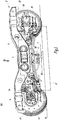
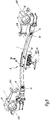
- the figure 1 partially represents a first subset E forming part of a railway vehicle bogie 100.
- a metro bogie 100 it being understood that the invention also applies to other types of rail vehicles, including trains or trams.
- the rail vehicle is able to run on a railway track which comprises two first parallel rails R1 and two second rails R2 each arranged along one of the first rails R1.
- a single first rail R1 or “rail” and only one second rail R2 or “third rail” are shown in FIG. figure 1 each by a line in phantom.
- the bogie 100 comprises four wheels of which two 1A and 1B are part of the first subset E of the figure 1 .
- the wheels 1A and 1B are intended to be supported by the first rail R1.
- the other two wheels of the bogie 100 are part of a second subset similar to the first subset E and are intended to be supported by the other first rail R1, which is not shown in the figures.
- the following description relates to the first subset E of the bogie 100, it being understood that it applies similarly to the second subset.
- Each wheel 1A and 1B is guided in rotation, about an axis X1A or X1B, in an axle box 2A and 2B of the bogie 100.
- a spar 5 forms a connecting element which mechanically connects the gearboxes.
- axle 2A and 2B The spar 5 is articulated in rotation with each axle box 2A and 2B around an X2A or X2B parallel to the axes X1A and X1 B.
- the spar 5 is a metal part sized to support the weight of the railway vehicle and transmit it to the axle boxes 2A and 2B.
- the terms “horizontal”, “vertical”, “high” and “low” are defined with respect to the terrestrial gravity field G, oriented vertically and from top to bottom. These terms correspond to the orientation of the bogie 100 in the figures and in the use configuration of the truck 100 where the wheels 1 A and 1B rest on the first rail R 1 which is horizontal.
- axle boxes 2A and 2B are also connected to the spar 5 via dampers 3A and 3B which attenuate the shocks and vibrations of the railway vehicle in the vertical direction.
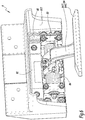
- the axle boxes 2A and 2B are further mechanically interconnected by a beam 7 which supports a member 8 for transmitting the electric current flowing between the first and second rails R1 and R2.
- the beam 7 is a separate element of the spar 5, it does not support the weight of the railway vehicle.
- the member 8 also called “current sensor”, is electrically connected to a fuse box 6 fixed to the spar 5.
- a potential difference is present between the first rails R1 on the one hand, and the second rails R2 on the other hand, so as to establish the flow of electric current.
- the electrical potential of the first rails R1 is zero
- the electric potential of the second rails R2 is equal to 750 V, sometimes equal to 1500 V.
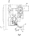
- the current sensor 8 is fixed by means of four bolts 80 on a median zone of the beam 7.
- the beam 7 comprises means for assembling the beam with the current sensor 8, constituted by holes not visible in the figures. who receive the bolt rods 80.
- the current sensor 8 comprises a body 82 and a wiper 84 composed of an arm 842 rotatably articulated about an axis Y8 perpendicular to the axes X1 A and X1 B, with a carriage 83.
- a wafer 844 provided to rub against the second rail R2 is connected to the arm 842.
- the wiper 84 is monobloc.
- the arm 842 and the plate 844 are two separate parts that are assembled together.
- the body 82 of the current sensor 8 is housed in a protective case 822 made from an electrically insulating material.
- Elastic return means such as torsion springs 86 tend to pivot the wiper 84 upwards in order to press the wafer 844 against a lower face F2 of a lateral wing R22 of the second rail R2, visible at the figure 4 .
- the wafer 844 is in contact with an upper face of the second rail R2.
- the elastic means 86 tend to rotate the wiper 84 downwards.
- Teeth are mounted on the carriage 83 and cooperate with racks 88 fixed to the body 82 of the current sensor 8.
- the slide 83 is movable in translation, in the vertical direction, relative to the body 82 of the current sensor 8.
- the mechanism of tooth and rack 88 integrated in the current sensor 8 makes it possible to adjust the height of the wiper 84 during the maintenance of the bogie 100, in order to compensate for the wear of the wheels 1 A and 1 B. In this way, a contact satisfactory is ensured between the plate 844 and the second rail R2. Locking means, such as screws, for fixing the slide 83 on the body 82, once the adjustment of the height of the carriage 83 is performed.
- the beam 7 is monobloc, that is to say made in one piece.
- the beam 7 is made from a metal alloy such as a structural steel, for example a steel grade S355 J2H.
- the beam 7 is hollow and is made by folding and welding a metal plate.
- the beam 7 thus comprises a longitudinal weld, not visible in the figures, which connects two edges of the metal plate from which the beam 7 is manufactured.
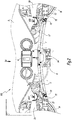
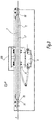
- the beam 7 extends along a line L7 which is curved in a direction from bottom to top.
- the line L7 corresponds to the neutral fiber of the beam 7.
- the line L7 is curved in a direction D which is included in a plane P perpendicular to the axes of rotation X1 A and X1 B of the wheels 1A and 1B.
- the direction D is perpendicular to a plane passing through the axes of rotation X1A and X1 B wheels 1 A and 1 B.
- the beam 7 has a cross section, taken perpendicular to the line L7, of square shape with rounded corners.
- the beam 7 does not result from the assembly of several elements, for example sections of profiles, and therefore does not include a transverse weld perpendicular to the line L7.
- the beam 7 is in the form of a circular arc portion C which is superimposed with the line L7.
- the radius of curvature of line L7 is constant along line L7 and is equal to the radius of arc portion C.
- the curved surface S is a curved surface which passes through the line L7 and which is parallel to the axes of rotation X1 A and X1 B of the wheels 1A and 1B.
- the curved surface S to the geometry of a circular section of a cylinder, having as radius that of the circle C.
- the center of the circle of curvature C is located on the same side of the curved surface S, namely below the curved surface S.
- the beam 7 is curved always in the same direction.
- the line L7 does not include inflection points, that is to say no concavity change.
- the radius of the circle of curvature C of the beam 7 is adapted to the vertical distance between the axle boxes 2A and 2B and the desired high position for the current sensor 8.
- the radius of the circle of curvature C is between 1000 mm and 5000 mm, preferably between 2000 and 4000 mm. In the example shown in the figures, the radius of curvature is equal to about 3060 mm.
- the beam 7 is coated with an electrically insulating coating that prevents the creep flow of parasitic currents.
- an electrically insulating coating that prevents the creep flow of parasitic currents.
- it may be a paint, a varnish, a surface treatment or a rilsanization operation.
- E1 and E2 are the longitudinal ends of the beam 7. At the ends E1 and E2, the beam 7 has open slots that allow the attachment of tabs 72, provided for fixing the beam 7 on the boxes.
- the fixing lugs 72 are fixed by means of bolts 70 on the beam 7 and are mounted at the bottom of the axle boxes 2A and 2B.
- the attachment of the beam 7 at the bottom of the axle boxes 2A and 2B is imposed by the overall geometry of the truck 100.
- the ends E1 and E2 of the beam 7 comprise passage holes for the bolts 70, these holes constituting means for fixing the beam 7 to the axle boxes 2A and 2B.
- force recovery pins are added to the bolts 70.
- a jig 200 shown in phantom lines delimits an outline that the elements constituting the bogie 100 must not exceed so that they do not come into contact with obstacles present along the railway.
- the curved shape of the beam 7 makes it possible to integrate the current sensor 8 with the bogie 100, without exceeding the limits of the jig 200.
- a) of manufacturing the bogie 100 the wheels 1A and 1B, the axle boxes 2A and 2B, the beam 7 and the current sensor 8 are manufactured separately.
- a straight metal bar is produced, for example by folding and welding a metal plate or by extrusion by means of a die.
- the belting is performed by means of a roller bender.
- the ends E1 and E2 of the beam 7 are assembled to the axle boxes 2A and 2B, by means of the attachment tabs 72, and the current sensor 8 is fixed on the beam 7 with the bolts 80.
- the beam 7 and the current sensor 8 undergo violent shocks and vibrations.
- the curved shape of the beam 7 gives it a satisfactory mechanical strength to withstand these mechanical stresses.
- the curvature towards the top of the beam 7 makes it possible to limit the amplitude of the deformations of the beam 7 when it is subjected to the forces related to the weight of the current sensor 8.
- the beam 7 of the invention has its own modes of vibration whose frequency is higher, which reduces the vibrations experienced by the current sensor 8.
- the constraints mechanical forces experienced by the beam 7 and the current sensor 8 are decreased.
- the beam 7 can then be fixed in other areas of the bogie 100 as for example the chassis of the truck 100, including the spar 5.
- the direction of the curvature of the beam 7 may then be different from that of the example shown in the figures.
- the beam 7 can be curved down.
- the beam 7 has any cross section, for example a circular section, I or U.
- the beam 7 is full.
- the radius of curvature of line L7 varies along line L7 in a continuous manner.
- the circle of curvature C has a radius that varies continuously.
- the circle C corresponds to the circle of curvature of the line L7 and is tangent to the line L7.
- the circle of curvature is still called the osculating circle. For each point of line L7, it is the circle that follows line L7 as best as possible.
- the radius of curvature of the line L7 is continuously variable, in other words the variations of the radius of the circle of curvature are zero or continuous.
- the shape of the line L7 does not show any breaks.
- the beam 7 has the shape of an arc of a circle, as shown in the figures.
- the bogie 100 as a whole comprises four wheels, four axle boxes, two axles, two longitudinal members and two current sensors.
Landscapes
- Engineering & Computer Science (AREA)
- Mechanical Engineering (AREA)
- Power Engineering (AREA)
- Transportation (AREA)
- Current-Collector Devices For Electrically Propelled Vehicles (AREA)
- Electric Propulsion And Braking For Vehicles (AREA)
- Vehicle Body Suspensions (AREA)
Applications Claiming Priority (2)
| Application Number | Priority Date | Filing Date | Title |
|---|---|---|---|
| FR1360238A FR3012087B1 (fr) | 2013-10-21 | 2013-10-21 | Bogie de vehicule ferroviaire et procede de fabrication d'un tel bogie |
| PCT/EP2014/072338 WO2015059052A1 (fr) | 2013-10-21 | 2014-10-17 | Bogie de vehicule ferroviaire et procede de fabrication d'un tel bogie |
Publications (2)
| Publication Number | Publication Date |
|---|---|
| EP3060450A1 EP3060450A1 (fr) | 2016-08-31 |
| EP3060450B1 true EP3060450B1 (fr) | 2017-06-21 |
Family
ID=49667486
Family Applications (1)
| Application Number | Title | Priority Date | Filing Date |
|---|---|---|---|
| EP14786863.2A Active EP3060450B1 (fr) | 2013-10-21 | 2014-10-17 | Bogie de vehicule ferroviaire et procede de fabrication d'un tel bogie |
Country Status (7)
| Country | Link |
|---|---|
| EP (1) | EP3060450B1 (enExample) |
| JP (1) | JP6397925B2 (enExample) |
| CN (1) | CN105658498B (enExample) |
| AR (1) | AR098124A1 (enExample) |
| BR (1) | BR112016008273B1 (enExample) |
| FR (1) | FR3012087B1 (enExample) |
| WO (1) | WO2015059052A1 (enExample) |
Cited By (1)
| Publication number | Priority date | Publication date | Assignee | Title |
|---|---|---|---|---|
| WO2023247933A3 (en) * | 2022-06-22 | 2024-02-01 | First Greater Western Limited | Current collection shoe apparatus |
Families Citing this family (5)
| Publication number | Priority date | Publication date | Assignee | Title |
|---|---|---|---|---|
| CN106428085B (zh) * | 2016-09-30 | 2018-08-24 | 中车南京浦镇车辆有限公司 | 一种转向架用高强度防断线缆支架 |
| JP6774314B2 (ja) * | 2016-11-24 | 2020-10-21 | 川崎重工業株式会社 | 鉄道車両用台車 |
| JP6898754B2 (ja) * | 2017-03-13 | 2021-07-07 | 川崎重工業株式会社 | 鉄道車両用台車 |
| CN111688750B (zh) * | 2020-06-30 | 2024-08-30 | 中车工业研究院有限公司 | 径向转向架 |
| DE102022206109A1 (de) * | 2022-06-20 | 2023-12-21 | Siemens Mobility GmbH | Fahrwerk für ein Schienenfahrzeug und Schienenfahrzeug |
Family Cites Families (12)
| Publication number | Priority date | Publication date | Assignee | Title |
|---|---|---|---|---|
| US1378695A (en) * | 1918-11-20 | 1921-05-17 | Electric Service Supplies Co | Contact-shoe |
| JPS5232812U (enExample) * | 1975-08-30 | 1977-03-08 | ||
| JPS5322406U (enExample) * | 1976-08-04 | 1978-02-24 | ||
| JPS6036965Y2 (ja) * | 1980-12-17 | 1985-11-02 | 株式会社東芝 | 電気鉄道車両の第三軌条集電装置 |
| DE3223989C2 (de) * | 1982-06-26 | 1986-09-04 | MAN Gutehoffnungshütte GmbH, 4200 Oberhausen | Laufwerk für Schienenfahrzeuge |
| US4526108A (en) * | 1984-06-11 | 1985-07-02 | Lukens General Industries, Inc. | Means for supporting third rail collector gear and the like on inside bearing railway trucks |
| US6079335A (en) * | 1999-02-23 | 2000-06-27 | Buckeye Steel Castings Company | Unsprung third rail collector beam support for a swing arm primary suspension railway truck |
| US8348035B2 (en) * | 2009-12-10 | 2013-01-08 | Schunk Bahn- Und Industrietechnik Gmbh | Pressing-on device for a current collector and method for energy transmission |
| JP2012130142A (ja) * | 2010-12-14 | 2012-07-05 | Sumitomo Metal Ind Ltd | 鉄道車両用集電装置 |
| US8839921B2 (en) * | 2011-09-29 | 2014-09-23 | Schunk Bahn-Und Industrietechnik Gmbh | Pressure plate assembly and method for power transmission |
| CN103010248B (zh) * | 2012-12-18 | 2016-03-30 | 唐山轨道客车有限责任公司 | 轨道车辆转向架 |
| CN103057424A (zh) * | 2013-01-06 | 2013-04-24 | 西南交通大学 | 一种轨道机车车辆滚动受电装置 |
-
2013
- 2013-10-21 FR FR1360238A patent/FR3012087B1/fr active Active
-
2014
- 2014-10-17 EP EP14786863.2A patent/EP3060450B1/fr active Active
- 2014-10-17 JP JP2016548425A patent/JP6397925B2/ja active Active
- 2014-10-17 WO PCT/EP2014/072338 patent/WO2015059052A1/fr not_active Ceased
- 2014-10-17 CN CN201480057527.6A patent/CN105658498B/zh active Active
- 2014-10-17 BR BR112016008273-7A patent/BR112016008273B1/pt active IP Right Grant
- 2014-10-20 AR ARP140103933A patent/AR098124A1/es active IP Right Grant
Non-Patent Citations (1)
| Title |
|---|
| None * |
Cited By (1)
| Publication number | Priority date | Publication date | Assignee | Title |
|---|---|---|---|---|
| WO2023247933A3 (en) * | 2022-06-22 | 2024-02-01 | First Greater Western Limited | Current collection shoe apparatus |
Also Published As
| Publication number | Publication date |
|---|---|
| AR098124A1 (es) | 2016-05-04 |
| BR112016008273B1 (pt) | 2022-05-31 |
| JP2016534940A (ja) | 2016-11-10 |
| FR3012087B1 (fr) | 2015-12-04 |
| WO2015059052A1 (fr) | 2015-04-30 |
| JP6397925B2 (ja) | 2018-09-26 |
| FR3012087A1 (fr) | 2015-04-24 |
| CN105658498B (zh) | 2017-12-05 |
| EP3060450A1 (fr) | 2016-08-31 |
| BR112016008273A2 (enExample) | 2017-08-01 |
| CN105658498A (zh) | 2016-06-08 |
Similar Documents
| Publication | Publication Date | Title |
|---|---|---|
| EP3060450B1 (fr) | Bogie de vehicule ferroviaire et procede de fabrication d'un tel bogie | |
| EP0983922B1 (fr) | Bogie à longerons composites | |
| EP3034375B1 (fr) | Bogie motorisé pour un véhicule ferroviaire à plancher surbaissé | |
| EP4077105B1 (fr) | Structure de partie arriere de caisse de vehicule automobile equipee de longerons et longeronnets | |
| EP3378723B1 (fr) | Bogie de véhicule ferroviaire comprenant des essieux fixés rigidement au châssis du bogie | |
| FR2511961A1 (fr) | Suspension primaire pour vehicule ferroviaire | |
| EP0238426B1 (fr) | Suspension à lames, notamment pour véhicules automobiles | |
| EP3222485B1 (fr) | Bogie de vehicule ferroviaire comprenant un dispositif de suspension primaire decale | |
| AT514373A1 (de) | Radsatzlagerung für den Radsatz eines Schienenfahrzeugs mit innengelagertem Drehgestell | |
| CA2736696C (fr) | Bogie moteur | |
| EP2476600B1 (fr) | Bogie de véhicule ferroviaire suspendu | |
| EP3974283B1 (fr) | Bogie de véhicule ferroviaire et véhicule associé | |
| EP3028918B1 (fr) | Châssis de bogie pour véhicule ferroviaire, bogie associé et procédé de fabrication d'un tel châssis de bogie | |
| FR3049252A1 (fr) | Bogie comprenant une liaison rigide entre les boites d'essieu, et vehicule ferroviaire associe | |
| FR2533521A1 (fr) | Suspension primaire de bogie de chemin de fer | |
| EP3275761B1 (fr) | Ensemble de traction pour attelage ferroviaire, et vehicule ferroviaire comprenant un tel ensemble | |
| FR3116255A1 (fr) | Bogie de véhicule ferroviaire, véhicule ferroviaire et procédé d’usinage associés | |
| EP3264940B1 (fr) | Glissière pour des systèmes de réglage coulissants | |
| EP3027442B1 (fr) | Train de roulement pour un véhicule automobile | |
| FR2861335A1 (fr) | Train de vehicule incluant une liaison flexible | |
| EP3650305B1 (fr) | Bogie et véhicule ferroviaire | |
| EP2213487A1 (fr) | Train arrière pour véhicule automobile comprenant deux ressorts latéraux en matériaux composites | |
| FR2491850A1 (fr) | Bogie de chemin de fer autodirecteur | |
| FR2669596A1 (fr) | Bogie pour vehicule ferroviaire comprenant un chassis en materiau composite. | |
| FR3161154A1 (fr) | Module de support pour cales de suspension et palier de barre stabilisatrice |
Legal Events
| Date | Code | Title | Description |
|---|---|---|---|
| PUAI | Public reference made under article 153(3) epc to a published international application that has entered the european phase |
Free format text: ORIGINAL CODE: 0009012 |
|
| 17P | Request for examination filed |
Effective date: 20160420 |
|
| AK | Designated contracting states |
Kind code of ref document: A1 Designated state(s): AL AT BE BG CH CY CZ DE DK EE ES FI FR GB GR HR HU IE IS IT LI LT LU LV MC MK MT NL NO PL PT RO RS SE SI SK SM TR |
|
| AX | Request for extension of the european patent |
Extension state: BA ME |
|
| DAX | Request for extension of the european patent (deleted) | ||
| GRAP | Despatch of communication of intention to grant a patent |
Free format text: ORIGINAL CODE: EPIDOSNIGR1 |
|
| INTG | Intention to grant announced |
Effective date: 20170213 |
|
| GRAS | Grant fee paid |
Free format text: ORIGINAL CODE: EPIDOSNIGR3 |
|
| GRAA | (expected) grant |
Free format text: ORIGINAL CODE: 0009210 |
|
| AK | Designated contracting states |
Kind code of ref document: B1 Designated state(s): AL AT BE BG CH CY CZ DE DK EE ES FI FR GB GR HR HU IE IS IT LI LT LU LV MC MK MT NL NO PL PT RO RS SE SI SK SM TR |
|
| REG | Reference to a national code |
Ref country code: GB Ref legal event code: FG4D Free format text: NOT ENGLISH |
|
| REG | Reference to a national code |
Ref country code: CH Ref legal event code: EP Ref country code: CH Ref legal event code: NV Representative=s name: ARNOLD AND SIEDSMA AG, CH |
|
| REG | Reference to a national code |
Ref country code: IE Ref legal event code: FG4D Free format text: LANGUAGE OF EP DOCUMENT: FRENCH |
|
| REG | Reference to a national code |
Ref country code: AT Ref legal event code: REF Ref document number: 902658 Country of ref document: AT Kind code of ref document: T Effective date: 20170715 |
|
| REG | Reference to a national code |
Ref country code: DE Ref legal event code: R096 Ref document number: 602014011077 Country of ref document: DE |
|
| REG | Reference to a national code |
Ref country code: SE Ref legal event code: TRGR |
|
| REG | Reference to a national code |
Ref country code: FR Ref legal event code: PLFP Year of fee payment: 4 |
|
| REG | Reference to a national code |
Ref country code: NL Ref legal event code: MP Effective date: 20170621 |
|
| PG25 | Lapsed in a contracting state [announced via postgrant information from national office to epo] |
Ref country code: HR Free format text: LAPSE BECAUSE OF FAILURE TO SUBMIT A TRANSLATION OF THE DESCRIPTION OR TO PAY THE FEE WITHIN THE PRESCRIBED TIME-LIMIT Effective date: 20170621 Ref country code: LT Free format text: LAPSE BECAUSE OF FAILURE TO SUBMIT A TRANSLATION OF THE DESCRIPTION OR TO PAY THE FEE WITHIN THE PRESCRIBED TIME-LIMIT Effective date: 20170621 Ref country code: GR Free format text: LAPSE BECAUSE OF FAILURE TO SUBMIT A TRANSLATION OF THE DESCRIPTION OR TO PAY THE FEE WITHIN THE PRESCRIBED TIME-LIMIT Effective date: 20170922 Ref country code: FI Free format text: LAPSE BECAUSE OF FAILURE TO SUBMIT A TRANSLATION OF THE DESCRIPTION OR TO PAY THE FEE WITHIN THE PRESCRIBED TIME-LIMIT Effective date: 20170621 Ref country code: NO Free format text: LAPSE BECAUSE OF FAILURE TO SUBMIT A TRANSLATION OF THE DESCRIPTION OR TO PAY THE FEE WITHIN THE PRESCRIBED TIME-LIMIT Effective date: 20170921 |
|
| REG | Reference to a national code |
Ref country code: LT Ref legal event code: MG4D |
|
| PG25 | Lapsed in a contracting state [announced via postgrant information from national office to epo] |
Ref country code: RS Free format text: LAPSE BECAUSE OF FAILURE TO SUBMIT A TRANSLATION OF THE DESCRIPTION OR TO PAY THE FEE WITHIN THE PRESCRIBED TIME-LIMIT Effective date: 20170621 Ref country code: NL Free format text: LAPSE BECAUSE OF FAILURE TO SUBMIT A TRANSLATION OF THE DESCRIPTION OR TO PAY THE FEE WITHIN THE PRESCRIBED TIME-LIMIT Effective date: 20170621 Ref country code: LV Free format text: LAPSE BECAUSE OF FAILURE TO SUBMIT A TRANSLATION OF THE DESCRIPTION OR TO PAY THE FEE WITHIN THE PRESCRIBED TIME-LIMIT Effective date: 20170621 Ref country code: BG Free format text: LAPSE BECAUSE OF FAILURE TO SUBMIT A TRANSLATION OF THE DESCRIPTION OR TO PAY THE FEE WITHIN THE PRESCRIBED TIME-LIMIT Effective date: 20170921 |
|
| PG25 | Lapsed in a contracting state [announced via postgrant information from national office to epo] |
Ref country code: CZ Free format text: LAPSE BECAUSE OF FAILURE TO SUBMIT A TRANSLATION OF THE DESCRIPTION OR TO PAY THE FEE WITHIN THE PRESCRIBED TIME-LIMIT Effective date: 20170621 Ref country code: EE Free format text: LAPSE BECAUSE OF FAILURE TO SUBMIT A TRANSLATION OF THE DESCRIPTION OR TO PAY THE FEE WITHIN THE PRESCRIBED TIME-LIMIT Effective date: 20170621 Ref country code: SK Free format text: LAPSE BECAUSE OF FAILURE TO SUBMIT A TRANSLATION OF THE DESCRIPTION OR TO PAY THE FEE WITHIN THE PRESCRIBED TIME-LIMIT Effective date: 20170621 Ref country code: RO Free format text: LAPSE BECAUSE OF FAILURE TO SUBMIT A TRANSLATION OF THE DESCRIPTION OR TO PAY THE FEE WITHIN THE PRESCRIBED TIME-LIMIT Effective date: 20170621 |
|
| PG25 | Lapsed in a contracting state [announced via postgrant information from national office to epo] |
Ref country code: SM Free format text: LAPSE BECAUSE OF FAILURE TO SUBMIT A TRANSLATION OF THE DESCRIPTION OR TO PAY THE FEE WITHIN THE PRESCRIBED TIME-LIMIT Effective date: 20170621 Ref country code: IS Free format text: LAPSE BECAUSE OF FAILURE TO SUBMIT A TRANSLATION OF THE DESCRIPTION OR TO PAY THE FEE WITHIN THE PRESCRIBED TIME-LIMIT Effective date: 20171021 Ref country code: PL Free format text: LAPSE BECAUSE OF FAILURE TO SUBMIT A TRANSLATION OF THE DESCRIPTION OR TO PAY THE FEE WITHIN THE PRESCRIBED TIME-LIMIT Effective date: 20170621 Ref country code: ES Free format text: LAPSE BECAUSE OF FAILURE TO SUBMIT A TRANSLATION OF THE DESCRIPTION OR TO PAY THE FEE WITHIN THE PRESCRIBED TIME-LIMIT Effective date: 20170621 |
|
| REG | Reference to a national code |
Ref country code: DE Ref legal event code: R097 Ref document number: 602014011077 Country of ref document: DE |
|
| PLBE | No opposition filed within time limit |
Free format text: ORIGINAL CODE: 0009261 |
|
| STAA | Information on the status of an ep patent application or granted ep patent |
Free format text: STATUS: NO OPPOSITION FILED WITHIN TIME LIMIT |
|
| PG25 | Lapsed in a contracting state [announced via postgrant information from national office to epo] |
Ref country code: DK Free format text: LAPSE BECAUSE OF FAILURE TO SUBMIT A TRANSLATION OF THE DESCRIPTION OR TO PAY THE FEE WITHIN THE PRESCRIBED TIME-LIMIT Effective date: 20170621 |
|
| 26N | No opposition filed |
Effective date: 20180322 |
|
| PG25 | Lapsed in a contracting state [announced via postgrant information from national office to epo] |
Ref country code: MC Free format text: LAPSE BECAUSE OF FAILURE TO SUBMIT A TRANSLATION OF THE DESCRIPTION OR TO PAY THE FEE WITHIN THE PRESCRIBED TIME-LIMIT Effective date: 20170621 |
|
| REG | Reference to a national code |
Ref country code: IE Ref legal event code: MM4A |
|
| PG25 | Lapsed in a contracting state [announced via postgrant information from national office to epo] |
Ref country code: LU Free format text: LAPSE BECAUSE OF NON-PAYMENT OF DUE FEES Effective date: 20171017 |
|
| REG | Reference to a national code |
Ref country code: BE Ref legal event code: MM Effective date: 20171031 |
|
| PG25 | Lapsed in a contracting state [announced via postgrant information from national office to epo] |
Ref country code: BE Free format text: LAPSE BECAUSE OF NON-PAYMENT OF DUE FEES Effective date: 20171031 Ref country code: SI Free format text: LAPSE BECAUSE OF FAILURE TO SUBMIT A TRANSLATION OF THE DESCRIPTION OR TO PAY THE FEE WITHIN THE PRESCRIBED TIME-LIMIT Effective date: 20170621 |
|
| REG | Reference to a national code |
Ref country code: FR Ref legal event code: PLFP Year of fee payment: 5 |
|
| PG25 | Lapsed in a contracting state [announced via postgrant information from national office to epo] |
Ref country code: MT Free format text: LAPSE BECAUSE OF FAILURE TO SUBMIT A TRANSLATION OF THE DESCRIPTION OR TO PAY THE FEE WITHIN THE PRESCRIBED TIME-LIMIT Effective date: 20170621 |
|
| PG25 | Lapsed in a contracting state [announced via postgrant information from national office to epo] |
Ref country code: IE Free format text: LAPSE BECAUSE OF NON-PAYMENT OF DUE FEES Effective date: 20171017 |
|
| PG25 | Lapsed in a contracting state [announced via postgrant information from national office to epo] |
Ref country code: HU Free format text: LAPSE BECAUSE OF FAILURE TO SUBMIT A TRANSLATION OF THE DESCRIPTION OR TO PAY THE FEE WITHIN THE PRESCRIBED TIME-LIMIT; INVALID AB INITIO Effective date: 20141017 |
|
| PG25 | Lapsed in a contracting state [announced via postgrant information from national office to epo] |
Ref country code: CY Free format text: LAPSE BECAUSE OF FAILURE TO SUBMIT A TRANSLATION OF THE DESCRIPTION OR TO PAY THE FEE WITHIN THE PRESCRIBED TIME-LIMIT Effective date: 20170621 |
|
| PG25 | Lapsed in a contracting state [announced via postgrant information from national office to epo] |
Ref country code: MK Free format text: LAPSE BECAUSE OF FAILURE TO SUBMIT A TRANSLATION OF THE DESCRIPTION OR TO PAY THE FEE WITHIN THE PRESCRIBED TIME-LIMIT Effective date: 20170621 |
|
| REG | Reference to a national code |
Ref country code: AT Ref legal event code: UEP Ref document number: 902658 Country of ref document: AT Kind code of ref document: T Effective date: 20170621 |
|
| PG25 | Lapsed in a contracting state [announced via postgrant information from national office to epo] |
Ref country code: PT Free format text: LAPSE BECAUSE OF FAILURE TO SUBMIT A TRANSLATION OF THE DESCRIPTION OR TO PAY THE FEE WITHIN THE PRESCRIBED TIME-LIMIT Effective date: 20170621 |
|
| PG25 | Lapsed in a contracting state [announced via postgrant information from national office to epo] |
Ref country code: AL Free format text: LAPSE BECAUSE OF FAILURE TO SUBMIT A TRANSLATION OF THE DESCRIPTION OR TO PAY THE FEE WITHIN THE PRESCRIBED TIME-LIMIT Effective date: 20170621 |
|
| PGFP | Annual fee paid to national office [announced via postgrant information from national office to epo] |
Ref country code: DE Payment date: 20241010 Year of fee payment: 11 |
|
| PGFP | Annual fee paid to national office [announced via postgrant information from national office to epo] |
Ref country code: GB Payment date: 20241028 Year of fee payment: 11 |
|
| PGFP | Annual fee paid to national office [announced via postgrant information from national office to epo] |
Ref country code: AT Payment date: 20240919 Year of fee payment: 11 |
|
| PGFP | Annual fee paid to national office [announced via postgrant information from national office to epo] |
Ref country code: IT Payment date: 20241010 Year of fee payment: 11 |
|
| PGFP | Annual fee paid to national office [announced via postgrant information from national office to epo] |
Ref country code: SE Payment date: 20241023 Year of fee payment: 11 |
|
| PGFP | Annual fee paid to national office [announced via postgrant information from national office to epo] |
Ref country code: CH Payment date: 20241101 Year of fee payment: 11 |
|
| PGFP | Annual fee paid to national office [announced via postgrant information from national office to epo] |
Ref country code: TR Payment date: 20241004 Year of fee payment: 11 |
|
| PGFP | Annual fee paid to national office [announced via postgrant information from national office to epo] |
Ref country code: FR Payment date: 20250909 Year of fee payment: 12 |
|
| REG | Reference to a national code |
Ref country code: CH Ref legal event code: U11 Free format text: ST27 STATUS EVENT CODE: U-0-0-U10-U11 (AS PROVIDED BY THE NATIONAL OFFICE) Effective date: 20251101 |