EP3059657A1 - Input apparatus and electronic device provided therewith - Google Patents
Input apparatus and electronic device provided therewith Download PDFInfo
- Publication number
- EP3059657A1 EP3059657A1 EP14853751.7A EP14853751A EP3059657A1 EP 3059657 A1 EP3059657 A1 EP 3059657A1 EP 14853751 A EP14853751 A EP 14853751A EP 3059657 A1 EP3059657 A1 EP 3059657A1
- Authority
- EP
- European Patent Office
- Prior art keywords
- section
- input
- input device
- detection surface
- support
- Prior art date
- Legal status (The legal status is an assumption and is not a legal conclusion. Google has not performed a legal analysis and makes no representation as to the accuracy of the status listed.)
- Granted
Links
- 238000001514 detection method Methods 0.000 claims abstract description 142
- 238000003825 pressing Methods 0.000 claims abstract description 67
- 230000005611 electricity Effects 0.000 claims abstract description 8
- 239000000758 substrate Substances 0.000 claims description 28
- 238000004891 communication Methods 0.000 claims description 13
- 230000002093 peripheral effect Effects 0.000 claims description 12
- 239000011159 matrix material Substances 0.000 claims description 4
- 238000010586 diagram Methods 0.000 description 27
- 230000000875 corresponding effect Effects 0.000 description 16
- 238000005516 engineering process Methods 0.000 description 15
- 238000000034 method Methods 0.000 description 11
- 230000008859 change Effects 0.000 description 8
- 239000000463 material Substances 0.000 description 6
- 230000006870 function Effects 0.000 description 5
- 230000009471 action Effects 0.000 description 3
- 230000002596 correlated effect Effects 0.000 description 3
- 239000011347 resin Substances 0.000 description 3
- 229920005989 resin Polymers 0.000 description 3
- 239000003086 colorant Substances 0.000 description 2
- 238000005401 electroluminescence Methods 0.000 description 2
- 238000003860 storage Methods 0.000 description 2
- XLYOFNOQVPJJNP-UHFFFAOYSA-N water Substances O XLYOFNOQVPJJNP-UHFFFAOYSA-N 0.000 description 2
- 210000000707 wrist Anatomy 0.000 description 2
- WHXSMMKQMYFTQS-UHFFFAOYSA-N Lithium Chemical compound [Li] WHXSMMKQMYFTQS-UHFFFAOYSA-N 0.000 description 1
- NIXOWILDQLNWCW-UHFFFAOYSA-N acrylic acid group Chemical group C(C=C)(=O)O NIXOWILDQLNWCW-UHFFFAOYSA-N 0.000 description 1
- 210000003423 ankle Anatomy 0.000 description 1
- 238000004364 calculation method Methods 0.000 description 1
- 239000013078 crystal Substances 0.000 description 1
- 230000000694 effects Effects 0.000 description 1
- 238000009413 insulation Methods 0.000 description 1
- 239000007788 liquid Substances 0.000 description 1
- 229910052744 lithium Inorganic materials 0.000 description 1
- 229910001416 lithium ion Inorganic materials 0.000 description 1
- 238000004519 manufacturing process Methods 0.000 description 1
- 238000012986 modification Methods 0.000 description 1
- 230000004048 modification Effects 0.000 description 1
- 239000004417 polycarbonate Substances 0.000 description 1
- 229920000515 polycarbonate Polymers 0.000 description 1
- 229920000642 polymer Polymers 0.000 description 1
- 238000010248 power generation Methods 0.000 description 1
- 230000009467 reduction Effects 0.000 description 1
- 238000005096 rolling process Methods 0.000 description 1
Images


Classifications
-
- G—PHYSICS
- G06—COMPUTING; CALCULATING OR COUNTING
- G06F—ELECTRIC DIGITAL DATA PROCESSING
- G06F1/00—Details not covered by groups G06F3/00 - G06F13/00 and G06F21/00
- G06F1/16—Constructional details or arrangements
- G06F1/1613—Constructional details or arrangements for portable computers
- G06F1/163—Wearable computers, e.g. on a belt
-
- G—PHYSICS
- G06—COMPUTING; CALCULATING OR COUNTING
- G06F—ELECTRIC DIGITAL DATA PROCESSING
- G06F3/00—Input arrangements for transferring data to be processed into a form capable of being handled by the computer; Output arrangements for transferring data from processing unit to output unit, e.g. interface arrangements
- G06F3/01—Input arrangements or combined input and output arrangements for interaction between user and computer
- G06F3/011—Arrangements for interaction with the human body, e.g. for user immersion in virtual reality
-
- G—PHYSICS
- G06—COMPUTING; CALCULATING OR COUNTING
- G06F—ELECTRIC DIGITAL DATA PROCESSING
- G06F3/00—Input arrangements for transferring data to be processed into a form capable of being handled by the computer; Output arrangements for transferring data from processing unit to output unit, e.g. interface arrangements
- G06F3/01—Input arrangements or combined input and output arrangements for interaction between user and computer
- G06F3/017—Gesture based interaction, e.g. based on a set of recognized hand gestures
-
- G—PHYSICS
- G06—COMPUTING; CALCULATING OR COUNTING
- G06F—ELECTRIC DIGITAL DATA PROCESSING
- G06F3/00—Input arrangements for transferring data to be processed into a form capable of being handled by the computer; Output arrangements for transferring data from processing unit to output unit, e.g. interface arrangements
- G06F3/01—Input arrangements or combined input and output arrangements for interaction between user and computer
- G06F3/03—Arrangements for converting the position or the displacement of a member into a coded form
- G06F3/033—Pointing devices displaced or positioned by the user, e.g. mice, trackballs, pens or joysticks; Accessories therefor
- G06F3/0354—Pointing devices displaced or positioned by the user, e.g. mice, trackballs, pens or joysticks; Accessories therefor with detection of 2D relative movements between the device, or an operating part thereof, and a plane or surface, e.g. 2D mice, trackballs, pens or pucks
- G06F3/03547—Touch pads, in which fingers can move on a surface
-
- G—PHYSICS
- G06—COMPUTING; CALCULATING OR COUNTING
- G06F—ELECTRIC DIGITAL DATA PROCESSING
- G06F3/00—Input arrangements for transferring data to be processed into a form capable of being handled by the computer; Output arrangements for transferring data from processing unit to output unit, e.g. interface arrangements
- G06F3/01—Input arrangements or combined input and output arrangements for interaction between user and computer
- G06F3/03—Arrangements for converting the position or the displacement of a member into a coded form
- G06F3/041—Digitisers, e.g. for touch screens or touch pads, characterised by the transducing means
- G06F3/0416—Control or interface arrangements specially adapted for digitisers
-
- G—PHYSICS
- G06—COMPUTING; CALCULATING OR COUNTING
- G06F—ELECTRIC DIGITAL DATA PROCESSING
- G06F3/00—Input arrangements for transferring data to be processed into a form capable of being handled by the computer; Output arrangements for transferring data from processing unit to output unit, e.g. interface arrangements
- G06F3/01—Input arrangements or combined input and output arrangements for interaction between user and computer
- G06F3/03—Arrangements for converting the position or the displacement of a member into a coded form
- G06F3/041—Digitisers, e.g. for touch screens or touch pads, characterised by the transducing means
- G06F3/044—Digitisers, e.g. for touch screens or touch pads, characterised by the transducing means by capacitive means
- G06F3/0445—Digitisers, e.g. for touch screens or touch pads, characterised by the transducing means by capacitive means using two or more layers of sensing electrodes, e.g. using two layers of electrodes separated by a dielectric layer
-
- G—PHYSICS
- G06—COMPUTING; CALCULATING OR COUNTING
- G06F—ELECTRIC DIGITAL DATA PROCESSING
- G06F3/00—Input arrangements for transferring data to be processed into a form capable of being handled by the computer; Output arrangements for transferring data from processing unit to output unit, e.g. interface arrangements
- G06F3/01—Input arrangements or combined input and output arrangements for interaction between user and computer
- G06F3/03—Arrangements for converting the position or the displacement of a member into a coded form
- G06F3/041—Digitisers, e.g. for touch screens or touch pads, characterised by the transducing means
- G06F3/044—Digitisers, e.g. for touch screens or touch pads, characterised by the transducing means by capacitive means
- G06F3/0446—Digitisers, e.g. for touch screens or touch pads, characterised by the transducing means by capacitive means using a grid-like structure of electrodes in at least two directions, e.g. using row and column electrodes
-
- G—PHYSICS
- G06—COMPUTING; CALCULATING OR COUNTING
- G06F—ELECTRIC DIGITAL DATA PROCESSING
- G06F3/00—Input arrangements for transferring data to be processed into a form capable of being handled by the computer; Output arrangements for transferring data from processing unit to output unit, e.g. interface arrangements
- G06F3/01—Input arrangements or combined input and output arrangements for interaction between user and computer
- G06F3/03—Arrangements for converting the position or the displacement of a member into a coded form
- G06F3/041—Digitisers, e.g. for touch screens or touch pads, characterised by the transducing means
- G06F3/044—Digitisers, e.g. for touch screens or touch pads, characterised by the transducing means by capacitive means
- G06F3/0447—Position sensing using the local deformation of sensor cells
-
- G—PHYSICS
- G06—COMPUTING; CALCULATING OR COUNTING
- G06F—ELECTRIC DIGITAL DATA PROCESSING
- G06F3/00—Input arrangements for transferring data to be processed into a form capable of being handled by the computer; Output arrangements for transferring data from processing unit to output unit, e.g. interface arrangements
- G06F3/01—Input arrangements or combined input and output arrangements for interaction between user and computer
- G06F3/048—Interaction techniques based on graphical user interfaces [GUI]
- G06F3/0487—Interaction techniques based on graphical user interfaces [GUI] using specific features provided by the input device, e.g. functions controlled by the rotation of a mouse with dual sensing arrangements, or of the nature of the input device, e.g. tap gestures based on pressure sensed by a digitiser
- G06F3/0488—Interaction techniques based on graphical user interfaces [GUI] using specific features provided by the input device, e.g. functions controlled by the rotation of a mouse with dual sensing arrangements, or of the nature of the input device, e.g. tap gestures based on pressure sensed by a digitiser using a touch-screen or digitiser, e.g. input of commands through traced gestures
- G06F3/04883—Interaction techniques based on graphical user interfaces [GUI] using specific features provided by the input device, e.g. functions controlled by the rotation of a mouse with dual sensing arrangements, or of the nature of the input device, e.g. tap gestures based on pressure sensed by a digitiser using a touch-screen or digitiser, e.g. input of commands through traced gestures for inputting data by handwriting, e.g. gesture or text
-
- G—PHYSICS
- G06—COMPUTING; CALCULATING OR COUNTING
- G06F—ELECTRIC DIGITAL DATA PROCESSING
- G06F3/00—Input arrangements for transferring data to be processed into a form capable of being handled by the computer; Output arrangements for transferring data from processing unit to output unit, e.g. interface arrangements
- G06F3/16—Sound input; Sound output
-
- G—PHYSICS
- G08—SIGNALLING
- G08C—TRANSMISSION SYSTEMS FOR MEASURED VALUES, CONTROL OR SIMILAR SIGNALS
- G08C17/00—Arrangements for transmitting signals characterised by the use of a wireless electrical link
-
- G—PHYSICS
- G08—SIGNALLING
- G08C—TRANSMISSION SYSTEMS FOR MEASURED VALUES, CONTROL OR SIMILAR SIGNALS
- G08C17/00—Arrangements for transmitting signals characterised by the use of a wireless electrical link
- G08C17/02—Arrangements for transmitting signals characterised by the use of a wireless electrical link using a radio link
-
- G—PHYSICS
- G06—COMPUTING; CALCULATING OR COUNTING
- G06F—ELECTRIC DIGITAL DATA PROCESSING
- G06F2203/00—Indexing scheme relating to G06F3/00 - G06F3/048
- G06F2203/048—Indexing scheme relating to G06F3/048
- G06F2203/04808—Several contacts: gestures triggering a specific function, e.g. scrolling, zooming, right-click, when the user establishes several contacts with the surface simultaneously; e.g. using several fingers or a combination of fingers and pen
-
- G—PHYSICS
- G06—COMPUTING; CALCULATING OR COUNTING
- G06F—ELECTRIC DIGITAL DATA PROCESSING
- G06F3/00—Input arrangements for transferring data to be processed into a form capable of being handled by the computer; Output arrangements for transferring data from processing unit to output unit, e.g. interface arrangements
- G06F3/01—Input arrangements or combined input and output arrangements for interaction between user and computer
- G06F3/016—Input arrangements with force or tactile feedback as computer generated output to the user
-
- G—PHYSICS
- G08—SIGNALLING
- G08C—TRANSMISSION SYSTEMS FOR MEASURED VALUES, CONTROL OR SIMILAR SIGNALS
- G08C2201/00—Transmission systems of control signals via wireless link
- G08C2201/30—User interface
-
- G—PHYSICS
- G08—SIGNALLING
- G08C—TRANSMISSION SYSTEMS FOR MEASURED VALUES, CONTROL OR SIMILAR SIGNALS
- G08C2201/00—Transmission systems of control signals via wireless link
- G08C2201/30—User interface
- G08C2201/32—Remote control based on movements, attitude of remote control device
-
- G—PHYSICS
- G08—SIGNALLING
- G08C—TRANSMISSION SYSTEMS FOR MEASURED VALUES, CONTROL OR SIMILAR SIGNALS
- G08C2201/00—Transmission systems of control signals via wireless link
- G08C2201/90—Additional features
- G08C2201/93—Remote control using other portable devices, e.g. mobile phone, PDA, laptop
Definitions
- the present technology relates to a user wearable input device and electronic apparatus including the same.
- Patent Document 1 discloses an input device including capacitative elements.
- the input device has a configuration that can detect pressing of a detection surface by a manipulator such as a finger.
- Patent Document 1 Japanese Patent Application Laid-open No. 2011-170659
- the electronic apparatus requires optimal portability, i.e., the electronic apparatus has to be readily available as necessary and does not obstruct the user's movements.
- an object of the present technology is to provide an input device having optimal portability and electronic apparatus including the same.
- An input device includes an input section, a control section, a power supply section, and a support section.
- the input section has a detection surface, and outputs a detection signal corresponding to a pressing position and a pressing amount on a detection surface.
- the control section determines the pressing position and the pressing amount based on the detection signal.
- the power supply section supplies electricity to the input section and the control section.
- the support section is user wearable, and supports the input section, the control section, and the power supply section.
- the input device may accept an input operation by user's pressing, and may be carried hands-free.
- the support section may be concatenated such that the input device is wearable on a user's arm.
- the detection surface may be formed at least one of an outer peripheral surface and an inner peripheral surface of the support section.
- the input device is wearable on a user's arm, whereby the user will be able to use the input device when necessary.
- the support section may support the input section, the control section, and the power supply section, and have a plurality of concatenated plate units.
- the input device can be concatenated.
- the support section may further include a hinge section that concatenates the plate units.
- the user can feel a comfortable fitting of the input device.
- a plurality of the plate units may include an input unit for supporting the input section, a control unit for supporting the control section, and a power supply unit for supporting the power supply section.
- each plate unit can have each function of the input device, the input device can be simply constituted.
- the input unit may have a plurality of the input units.
- the control section may determine the pressing position and the pressing amount per the plurality of input units.
- the input operation is possible by combining a plurality of the input units, thereby increasing flexibility of the input operation.
- the support section may include an elastically deformable C-shaped frame section.
- the input device may be ring-shaped.
- the input section may be configured to output a detection signal corresponding to an input operation of squeezing and pressing the detection surface in its own plane direction.
- the input device may further include a communication section supported by the support section and capable of transmitting an operation signal generated based on the pressing position and the pressing amount by the control section to an external device.
- the communication section may receive a signal from the external device.
- the control section may generate a control signal based on a signal received by the communication section.
- the input device can output corresponding to the signal from the external device.
- the input device may further include a notification section supported by the support section and configured to perform a notification based on the control signal.
- the notification section may include at least one of a light-emitting element, a sound-emitting element and a vibration element.
- the input device can perform a notification to a user corresponding to the signal from the external device.
- the input unit may further include a sensor substrate and an intermediate layer.
- the sensor substrate has a plurality of capacitative elements that are placed facing to the detection surface and are arranged in a matrix.
- the intermediate layer is placed between the detection surface and the sensor substrate and has a plurality of structures configured to deformably support the detection surface.
- the input unit may further include a conductive layer placed between the detection surface and the intermediate layer.
- the input unit can detect the pressing position and the pressing amount on the detection surface by a mutual capacitance method.
- the detection surface may include an input guide section configured by at least one of an image and a convex-concave shape.
- the input device can perform an input operation by a user to a correct position on the detection surface.
- the input unit may further include a display section on which the detection surface is provided and configured to display an image on the detection surface under control by the control section.
- the input device 1 can correspond to a variety of input operations by changing images displayed on the display section.
- An electronic apparatus includes an input section, a control section, a power supply section, a support section, and a display device.
- the input section has a detection surface, and outputs a detection signal corresponding to a pressing position and a pressing amount on a detection surface.
- the control section determines the pressing position and the pressing amount based on the detection signal.
- the power supply section supplies electricity to the input section and the control section.
- the support section is user wearable, and supports the input section, the control section, and the power supply section.
- the display device displays an image corresponding to the operation signal.
- the input device may accept an input operation by user's pressing, and may be carried hands-free.
- an input device having optimal portability and an electronic apparatus including the input device.
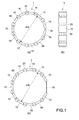
- Fig. 1(a) and Fig. 1(c) each is a side view diagram of an input device 1 according to a first embodiment of the present technology.
- Fig. 1(b) is a plan-view diagram of the input device 1.
- Fig. 1(a) and Fig. 1(b) each shows a status in which the input device 1 is in not use.
- Fig. 1(c) shows a status in which the input device 1 is in use.
- the input device 1 includes input units 10, a control unit 50, a notification unit 60, a power supply unit 70, hinge sections 20, a connection section 30, and wiring sections 40.
- the input device 1 is wearable similar to a wristwatch, and is wearable on a user's arm.
- the input device 1 constitutes a flat plate unit where eight input units 10, one control unit 50, one notification unit 60 and one power supply unit 70 are arranged along an outer periphery of a user's arm. In this manner, the user can carry the input device 1 hands-free.
- the hinge sections 20 constitute support sections for articulating the plate units (the input units 10, the control unit 50, the notification unit 60, the power supply unit 70). Each hinge section 20 supports two adjacent plate units such that an angle therebetween can be changed. Therefore, in the input device 1, the angle between the adjacent plate units can be changed corresponding to the shape of the user's arm, thereby providing a comfortable fitting.
- connection section 30 connects the plate units placed at both ends among a plurality of the plate units concatenated into one by the hinge sections 20. In this way, the input device 1 becomes ring-shaped.
- the plate units, the hinge sections 20 and the connection section 30 constitute a ring-shaped section of the input device 1.
- the connection section 30 is constituted of an elastic rubber material, for example.
- the connection section 30 is not limited to the configuration, and may have any configuration that the plate units placed at both ends can be connected.
- the connection section 30 may be a buckle used in a typical wristwatch.
- An inner diameter ⁇ A of the input device 1 not in use shown in Fig. 1(a) is set to be smaller than an inner diameter of a typical user's arm.
- the user wears the input device 1 on the arm by extending the connection section 30 from the status shown in Fig. 1(a) to the inner diameter through which a user's fist can be inserted.
- the inner diameter ⁇ B of the input device 1 worn by the user's arm shown in Fig. 1(c) is greater than the inner diameter ⁇ A, and the input device 1 is firmly fixed to the user's arm by an elastic force of the connection section 30.
- the wiring sections 40 are provided for electrically connecting adjacent plate units. That is to say, eight input units 10, one control unit 50, one notification unit 60 and one power supply unit 70 are mutually electrically connected by the wiring sections 40.
- the wiring sections 40 are constituted by a flexible print circuit, for example.
- the power supply unit 70 is adjacent to the connection section 30.
- the notification unit 60 is adjacent to the power supply unit 70
- the control unit 50 is adjacent to the notification unit 60. Since the input units 10 are preferably placed at the position where the user easily perform the input operation, the power supply unit 70, the notification unit 60 and the control unit 50 are tried to be placed at the position where the user is difficult to perform the input operation. Note that the input units 10, the control unit 50, the notification unit 60 and the power supply unit 70 are not limited to the configuration, and may constitute any plate units of the input device 1.
- Each input unit 10 can receive the input operation from the user.
- a plurality of the input units 10 may be used individually for different input operations, and may be used integrated.
- Each input unit 10 outputs a detection signal to the control unit 50 based on the user's input operation.
- the power supply unit 70 supplies electricity to the input units 10, the control unit 50 and the notification unit 60.
- the power supply unit 70 includes an power storage element and a power supply circuit, for example.
- Non-limiting examples of the power storage element applicable to the power supply unit 70 includes a lithium ion cell and a lithium polymer cell.
- the power supply unit 70 may include a power generation element such as a solar cell.
- the control unit 50 controls the input units 10, the notification unit 60 and the power supply unit 70.
- the control unit 50 typically includes a computer having CPU/MPU, a memory and the like.
- the control unit 50 includes a communication section for communicating with an electronic apparatus main body and an external device such as other input device 1.
- the electronic apparatus being capable of communicating with the input units 10 includes a smartphone and a portable audio player, and the like.
- the control unit 50 can transmit an operation signal generated based on the detection signal from the input units 10 to the electronic apparatus main body and other input device 1 by the communication section. Also, the control unit 50 receives the signal from the electronic apparatus main body and other input device 1, and can drive the input units 10, the notification unit 60 and the power supply unit 70 based on the signal received.
- the notification unit 60 a variety of parts for notifying the user are mounted. Examples of the parts mounted to the notification unit 60 include a sound-emitting element, a light-emitting element and a vibration element, for example.
- the notification unit 60 notifies a user by sound, light or vibration under the control by the control unit 50.
- the notification unit 60 having the sound-emitting element can notify a user of information based on a sound-emitting status of the sound-emitting element (tone color, sound-emitting time, type of melody, etc.).
- a sound-emitting status of the sound-emitting element tone color, sound-emitting time, type of melody, etc.
- a light-emitting diode is used, for example.
- the notification unit 60 having the light-emitting element can notify a user of information based on a light-emitting status of the light-emitting element (light-emitting intensity, light-emitting time, blink speed, blink pattern, etc.).
- a vibration motor is used, for example.
- the notification unit 60 having the vibration element can notify a user of information based on a vibration status of the vibration element (vibration intensity, vibration time, vibration frequency, etc.).
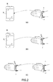
- Fig. 2 is a diagram illustrating a method of using the input device 1.
- the input device 1 can communicate with one electronic apparatus main body B pairing communicated with the input device 1, as shown in Fig. 2(a) and Fig. 2(b) , and can also communicate with the other input device 1 pairing communicated with the input device 1, as shown in Fig. 2(c) .
- Fig. 2 (a) shows a status in which the input device 1 is transmitting to the electronic apparatus main body B an operation signal based on an input operation by a user's finger f to the input device 1.
- the electronic apparatus main body B receives the operation signal from the input device 1, and exerts a variety of functions based on the operation signal received.
- the functions of the electronic apparatus main body B operable by the input device 1 are not especially limited. Examples of the functions of the electronic apparatus main body B include a display change of a screen S, receiving of e-mails, acquisition of positional information, switching speech and non-speech or the like.
- Fig. 2(b) shows a status in which the input device 1 receives the signal transmitting from the electronic apparatus main body B.
- the input device 1 notifies a user corresponding to the signal from the electronic apparatus main body B by the notification unit 60.
- the input device 1 adds vibration by the notification unit 60 when the input device 1 receives the signal showing that an e-mail is received from the electronic apparatus main body B.
- Fig. 2(c) shows that a status in which users wearing the input device 1 communicates with each other.
- the input device 1 on which one user performs the input operation transmits the operation signal
- the other input device 1 of the other user receives the operation signal and performs a notification based on the operation signal received.
- the input device 1 can make the communication between the users by utilizing light, sound, vibration or the like.
- the input device 1 includes a function that requires no communication with the external device such as the above-described electronic apparatus main body B and the other input device 1. For example, a user can see a cell's residual power of the power supply unit 70 by performing the input operation on the input device 1. In this case, when the cell's residual power of the input device 1 is small, melody is generated by the notification unit 60. In this way, the user can charge the input device 1 before the cell's residual power is short.
- Fig. 3 and Fig. 4 show an input unit 10.
- Fig. 3 is a plan-view diagram
- Fig. 4 is a cross sectional-view diagrams along an A-A' line in Fig. 3 .
- the input unit 10 has a substantially square plate shape.
- the input unit 10 has a concave case 11 and a sensor section 12 housed within the case 11.
- the case 11 forms a concave portion by a square plate bottom 11a and a side wall 11b provided along an outer periphery of the bottom 11a.
- the case 11 is formed of a resin material having rigidity and an insulation property.
- the sensor 12 has a sensor substrate 13, an intermediate layer 16, a conductive layer 17, and an outer layer 18.
- the outer layer 18 defines an external form of the input unit 10 together with the case 11.
- An outer surface (top surface) of the outer layer 18 constitutes a detection surface 18a that receives the input operation from the user.
- the sensor substrate 13 has a plurality of first electrode wires 14 and a plurality of second electrode wires 15 placed facing to a plurality of the first electrode wires 14 and intersecting with a plurality of the first electrode wires 14.
- the electrode wires 14, 15 constitute capacitative elements on the intersecting points. Accordingly, the sensor substrate 13 has a configuration that the capacitative elements are arranged in a matrix. An electrostatic capacity in each capacitative element of the substrate 13 changes depending on a distance between the sensor substrate 13 and the conductive layer 17.
- the outer layer 18 is formed of a resin material having flexibility.
- the conductive layer 17 is formed at an inner surface (lower surface) of the outer layer 18.
- the intermediate layer 16 is placed between the conductive layer 17 and the sensor substrate 13.
- the intermediate layer 16 is constructed of a plurality of columnar structures 16a sandwiched between the conductive layer 17 and the sensor substrate 13.
- the structures 16a are formed of a resin material having flexibility, for example.
- the conductive layer 17 is grounded and has a reference potential.
- the input unit 10 outputs a detection signal corresponding to the electrostatic capacity of the sensor substrate 13 to the control unit 50 (see Fig. 1 ).
- the control unit 50 determines a pressing position on the detection surface 18a and a pressing amount in the pressing position based on the detection signal from the input unit 10. In this way, the control unit 50 can calculate an operation position on the detection surface 18a, a pressing force to the detection surface 18a, a rolling reduction speed of the detection surface 18a, a moving distance of the finger f, a moving speed of the finger f and the like.
- the control unit 50 recognizes the input operation performed on the detection surface 18a based on the calculation results, and generates the operation signal that is associated with the input operation.
- the detection signal is generated when the detection surface 18a is pressed, but the detection signal is not generated when the user touches the detection surface 18a by mistake with no intention to perform the input operation. Accordingly, the input unit 10 prevents the user from doing erroneous operation.
- the detection signal is generated by the deformation of the conductive layer 17 accompanied by pressing the detection surface 18a. Accordingly, the input operation of the detection surface 18a can be performed not by a conductive manipulator such as the user's finger f and a stylus but by a user's hand, for example, wearing a glove. In addition, in the input unit 10, even when water droplets are attached to the detection surface 18a, the detection signal is less influenced. Furthermore, the input operation can be performed under water.
- the conductive layer 17 is not essential. Also, although the input unit 10 is constituted to form a sensor in a mutual capacitance method, the input unit 10 may be constituted to form a sensor in a self-capacitance method.
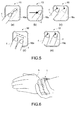
- Figs. 5 to 7 each is a diagram showing an operation example of the input device 1.
- Fig. 5(a) shows an input operation in which the detection surface 18a of the input unit 10 is pressed by the user's finger f to move the finger f on the detection surface 18a.
- the input operation for example, depending on the moving distance and the moving speed of the finger f, a pointer within the screen S of the electronic apparatus main body B (see Fig. 2 (a) and Fig. 2(b) ) can be moved.
- Fig. 5(b) shows an input operation in which the detection surface 18a of the input unit 10 is pressed by the user's finger f to move the finger f in one direction.
- the input operation for example, when the moving speed of the finger f exceeds a predetermined threshold value, the screen S in the display device of the electronic apparatus main body B can be moved to the moving direction of the finger f.
- Fig. 5(c) shows an input operation in which two positions on the detection surface 18a of the input unit 10 are pressed successively by the user's finger f.
- the input operation for example, depending on the distance between the two positions and the pressing force, a specific area within the screen S of the electronic apparatus main body B can be selected.
- Fig. 5(d) shows an input operation in which the detection surface 18a of the input unit 10 is pressed by two user's fingers f to change a distance between the two fingers f.
- the input operation for example, depending on the distance between the two fingers f and a change speed of the distance, the screen S of the electronic apparatus main body B can be zoomed in or zoomed out.
- Fig. 5(e) shows an input operation in which the detection surface 18a of the input unit 10 is pressed by the user's two fingers f.
- the input operation for example, depending on a deviation of a pressing timing and a difference in pressing forces by the two fingers f, the display in the screen S of the electronic apparatus main body B can be changed.
- control unit 50 not only generates individual operation signals for the respective input units 10, but also generates operation signals corresponding to multiple input operations to a plurality of the input units 10.
- the multiple input operations include an input operation by an order of pressing a plurality of the input units 10, for example.
- the input device 1 can be constituted such that the user can perform the input operation on successive detection surfaces 18a of a plurality of adjacent input units 10.
- Fig. 6 shows an input operation in which the user holds the input device 1 worn on one hand by an opposite hand.
- the control unit 50 can recognize the input operation when three or more input units 10 are pressed at the same time.
- a clock within the screen S of the electronic apparatus main body B can be enlarged and displayed.
- Fig. 7 shows an input operation in which the user picks the case 11 of the input unit 10 with one's fingers. More specifically, both ends of the detection surface 18a of the sensor section 12 are pressed (squeezed) via the side wall 11b of the case 11. At this time, the detection surface 18a is squeezed and pressed in its own plane direction, thereby flexing the detection surface 18a. This causes a characteristic change in the electrostatic capacity of the sensor substrate 13.
- the control unit 50 can recognize the input operation by the characteristic change in the electrostatic capacity. By the input operation, a display mode of the screen S of the electronic apparatus main body B can be switched.
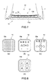
- Fig. 8 and Fig. 9 illustrate the detection surface 18a.
- the detection surface 18a has an input guide section for easily finding the position on the detection surface 18a.
- Fig. 8(a) to Fig. 8(d) and Fig. 9(a) each is a plan-view diagram of the input unit 10
- Fig. 9(b) is a side view diagram of the input unit 10.
- Images are drawn in the detection surfaces 18a shown in Fig. 8 .
- the images in the detection surface 18a are correlated with the positions in the detection surface 18a.
- the input device 1 is constituted such that when the images in the detection surface 18a are pressed, the control unit 50 generates the operation signal relating to the images.
- the input unit 10 may be constituted such that the outer layer 18 is a display section that displays the images on the detection surface 18a under the control unit 50.
- the input device 1 may change the images displayed on the detection surface 18a of each input unit 10 as appropriate.
- the images displayed on the detection surface 18a are correlated with the positions on the detection surface 18a.
- Such an input device 1 is constituted such that when the images displayed on the detection surface 18a are pressed, the control unit 50 generates an operation signal relating to the images.
- a grid is displayed on the detection surface 18a.
- the user will be able to press a more precise position on the detection surface 18a by means of the grid on the detection surface 18a
- other images may be displayed in addition to the grid.
- Fig. 8(b) characters, symbols and arrows are displayed on the detection surface 18a.
- the control unit 50 generates the operation signal correlated with the characters, the symbols and the arrows pressed based on the input operation.
- FIG. 8(c) an image of a jog dial and images of arrow keys are displayed on the detection surface 18a in addition to the characters.
- the screen S of the electronic apparatus main body B (see Fig. 2(a) and Fig. 2(b) ) can be scrolled, for example.
- a pointer within the screen S of the electronic apparatus main body B can be moved corresponding to the arrow keys.
- Fig. 8(d) four areas a1, a2, a3, a4 classified by colors are provided on the detection surface 18a.
- the user can more intuitively recognize the position on the detection surface 18a. In this way, the user will be able to press a more precise position of the detection surface 18a.
- Protrusions 18b each having a convex-concave shape are provided on the detection surface 18a shown in Fig. 9 .
- the user can recognize the protrusions 18b by touching. Accordingly, the user can press a precise position within the detection surface 18a without seeing the detection surface 18a.
- An input device 101 according to a second embodiment of the present technology is different from the input device 1 according to the first embodiment only as to the configuration of the input unit 110. Descriptions about the configurations of the input device 101 common to those according to the first embodiment will be omitted as appropriate.
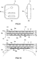
- Fig. 10 is cross sectional-view diagrams of the input unit 110 of the input device 101
- Fig. 11 is diagrams illustrating a method of operating the input device 101.
- the input unit 110 includes an intermediate layer 26, a conductive layer 27, and an outer layer 28 provided on the sensor substrate 13 opposite to the intermediate layer 16, the conductive layer 17 and the outer layer 18.
- the intermediate layer 26 is constituted by a plurality of columnar structures 26a sandwiched between the conductive layer 27 and the sensor substrate 13.
- An opening is formed at a central are of a bottom 111a of the case 111, and the outer layer 28 is exposed from the opening.
- An outer surface (lower surface) of the outer layer 28 is constituted as a detection surface 28a on which the user presses. That is to say, the input device 101 includes the detection surface 18a arranged along an outer peripheral surface and a detection surface 28a arranged along an inner peripheral surface. Note that the input device 101 may be constituted such that the detection surface 18a at an outer peripheral surface side is omitted.
- the control unit 50 when the detection surface 18a accepts an input operation and the conductive layer 17 becomes closer to the sensor substrate 13, the electrostatic capacity of sensor substrate 13 changes. Furthermore, in the input unit 110, when the detection surface 28a is pressed and the conductive layer 27 becomes closer to the sensor substrate 13, the electrostatic capacity of sensor substrate 13 changes. In the input unit 110, the control unit 50 generates the operation signal based on the input operation of the detection surface 18a, and generates the operation signal based on the pressing to the detection surface 28b.
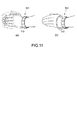
- the detection surface 28a of the input unit 110 is positioned at an inner periphery of the input device 101 and is therefore contacted with a user's arm wearing the input device 101. Accordingly, as shown in Fig. 10(b) , a pressing status of the detection surface 28a in each input unit 110 changes depending on an action of the user's arm. This changes the electrostatic capacity of the sensor substrate 13, whereby the control unit 50 can recognize the action of the user's arm as the input operation.
- Fig. 11(a) shows the input operation in which the user shakes the wrist
- Fig. 11(b) shows the input operation in which the user rotates the wrist.
- the outer layer 18 of the input unit 110 may be constituted as the display section that can display images or videos on the detection surface 18a.
- the display section is driven by the control signal generated by the control unit 50.
- the display section can display an image showing that an e-mail is received from the electronic apparatus main body B or a latest news video, for example.
- the display section is constituted by known displays such as a crystal liquid display and an organic EL (Electro-Luminescence) display.
- the control unit 50 can drive the display section independently for each input unit 110, and can drive the display section by taking all detection surfaces 18a of all input units 110 as one display section.
- the control unit 50 can display character images for each detection surface 18a of each input unit 110, and can display a long and narrow image and a character string image for all detection surfaces 18a of all input units 110.
- a certain pressing status by the user's arm is generated on each detection surface 28a at an inner peripheral surface side.
- the control unit 50 detects the certain pressing status on each detection surface 28a and recognizes that the input device 101 is worn by the user's arm, the operation signal can be generated.
- the control unit 50 can drive the display section, for example, by the operation signal.
- control unit 50 can recognize an attitude of the input device 101 for the arm based on the pressing status for each detection surface 28a. Specifically, the control unit 50 can recognize the rotation of the input device 101 to the user's arm in a circumferential direction. In this way, the control unit 50 can change the image displayed by each input unit 110 depending on the attitude of the input device 101. For example, the control unit 50 can continue to display a clock image on the display section of the input unit 110 nearest the predetermined position of the arm when the input device 101 rotates around the arm in the circumferential direction.
- An input device 201 according to a third embodiment of the present technology is different from the input device 1 according to the first embodiment only as to the configuration described below. Descriptions about the configurations of the input device 201 common to those according to the first embodiment will be omitted as appropriate.
- Fig. 12(a) and Fig. 12(c) each is a side view diagram of the input device 201 according to the third embodiment of the present technology
- Fig. 12(b) is a plan-view diagram of the input device 201
- Fig. 12(a) and Fig. 12(b) each shows a status in which the input device 201 is in not use
- Fig. 12(c) shows a status in which the input device 201 is in use.
- the input device 201 includes input units 210, a control unit 250, a notification unit 260, a power supply unit 270, linkage sections 220, a connection section 230, and wiring sections 240.
- the linkage sections 220 constitutes support sections that concatenate plate units (the input units 210, the control unit 250, the notification unit 260, the power supply unit 270). Each linkage section 220 is provided as a sheet by the material having flexibility similar to the connection section 230, and supports adjacent two plate units. Each of the linkage section 220 and the connection section may be provided independently, or all of the linkage sections 220 and the connection section 230 may be integrated and concatenated in ring shape. Also, the linkage sections 220 and the wiring sections 240 may be integrated and constituted by a flexible print circuit.
- An inner diameter ⁇ A of the input device 201 not in use shown in Fig. 12(a) is set to be smaller than an inner diameter of a typical user's arm.
- the user wears the input device 201 on the arm by extending the connection section 230 from the status shown in Fig. 12(a) to the inner diameter through which a user's fist can be inserted.
- the inner diameter ⁇ B of the input device 201 worn by the user's arm shown in Fig. 12(c) is greater than the inner diameter ⁇ A, and the input device 201 is firmly fixed to the user's arm by elastic forces of the connection section 230 and the linkage section 220.
- the input device 201 can be worn by the user's arm including no mechanical structure such as a hinge section. Accordingly, in the input device 201, parts costs and manufacturing costs are reduced.
- An input device 301 according to a fourth embodiment of the present technology is different from the input device 1 according to the first embodiment only as to the configuration described below. Descriptions about the configurations of the input device 301 common to those according to the first embodiment will be omitted as appropriate.
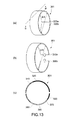
- Fig. 13(a) and Fig. 13(b) each is a perspective diagram of the input device 301 according to the fourth embodiment of the present technology.
- Fig. 13(c) is a cross sectional-view diagram of the input unit 301 along a B-B' line in Fig. 13(a).
- Fig. 13(a) and Fig. 13(c) each shows a status in which the input device 301 is in not use.
- Fig. 13(b) shows a status in which the input device 301 is in use.
- the input device 301 includes an input unit 310, a control unit 350, a notification unit 360, a power supply unit 370 and a frame section 320.
- the input unit 310, the control unit 350, the notification unit 360, the power supply unit 370 and the frame section 320 are integrated in a C shape with an elastically deformable material such as polycarbonate and acrylic.
- the frame section 320 constitutes a support section that supports the input unit 310, the control unit 350, the notification unit 360 and the power supply unit 370.
- the frame section 320 has ends 320a, 320b spaced each other.
- the input unit 310 is formed in a uniform thickness of about several mm in the whole circumference.
- the input unit 310, the control unit 350, the notification unit 360 and the power supply unit 370 are formed in an arc shape as shown in Fig. 13(c) and are electrically connected to each other.
- the input device 301 may be constituted by a plurality of input units 310.
- the plurality of the input units 310 may be placed side-by-side, or may be placed spaced apart.
- the detection surface of each input unit 310 is placed at least either of an outer peripheral surface and an inner peripheral surface of the input device 301.
- An inner diameter ⁇ A of the input device 301 not in use shown in Fig. 13(a) is set to be smaller than an inner diameter of a typical user's arm.
- the user wears the input device 301 on the arm by extending the ends 320a, 320b of the frame section 320 from the status shown in Fig. 12(a) to the inner diameter through which a user's fist can be inserted.
- the inner diameter ⁇ B of the input device 301 worn by the user's arm shown in Fig. 13(b) is greater than the inner diameter ⁇ A, and the input device 301 is firmly fixed to the user's arm by elastic forces of the input unit 310, the control unit 350, the notification unit 360, the power supply unit 370 and the frame section 320.
- the configuration of the input unit is not limited to have the sensor substrate including a plurality of capacitative elements and the intermediate layer placed between the detection surface and the sensor substrate, and may be that the detection signal may be output corresponding to the pressing position and the pressing amount on the detection surface.
- the input unit may have a configuration that a touch sensor, a pressure-sensitive sensor and a mechanical switch may be combined.
- the input device may be wearable on a part of a user's body other than the user's arm.
- the input device may be wearable on a user's finger, ankle or head.
- the present technology may have the following configurations.
Abstract
Description
- The present technology relates to a user wearable input device and electronic apparatus including the same.
- Generally, an input device is used for input operation of electronic apparatus.
Patent Document 1 discloses an input device including capacitative elements. The input device has a configuration that can detect pressing of a detection surface by a manipulator such as a finger. - Patent Document 1: Japanese Patent Application Laid-open No.
2011-170659 - In recent years, portable electronic apparatus including a smartphone has become essential for user's life. Therefore, the electronic apparatus requires optimal portability, i.e., the electronic apparatus has to be readily available as necessary and does not obstruct the user's movements.
- In view of the circumstances as described above, an object of the present technology is to provide an input device having optimal portability and electronic apparatus including the same.
- An input device according to the present disclosure includes an input section, a control section, a power supply section, and a support section.
- The input section has a detection surface, and outputs a detection signal corresponding to a pressing position and a pressing amount on a detection surface.
- The control section determines the pressing position and the pressing amount based on the detection signal.
- The power supply section supplies electricity to the input section and the control section.
- The support section is user wearable, and supports the input section, the control section, and the power supply section.
- Through this configuration, the input device may accept an input operation by user's pressing, and may be carried hands-free.
- The support section may be concatenated such that the input device is wearable on a user's arm.
- The detection surface may be formed at least one of an outer peripheral surface and an inner peripheral surface of the support section.
- Through this configuration, the input device is wearable on a user's arm, whereby the user will be able to use the input device when necessary.
- The support section may support the input section, the control section, and the power supply section, and have a plurality of concatenated plate units.
- Through this configuration, the input device can be concatenated.
- The support section may further include a hinge section that concatenates the plate units.
- Through this configuration, the user can feel a comfortable fitting of the input device.
- A plurality of the plate units may include an input unit for supporting the input section, a control unit for supporting the control section, and a power supply unit for supporting the power supply section.
- Through this configuration, as each plate unit can have each function of the input device, the input device can be simply constituted.
- The input unit may have a plurality of the input units.
- The control section may determine the pressing position and the pressing amount per the plurality of input units.
- Through this configuration, in the input device, the input operation is possible by combining a plurality of the input units, thereby increasing flexibility of the input operation.
- The support section may include an elastically deformable C-shaped frame section.
- Through this configuration, the input device may be ring-shaped.
- The input section may be configured to output a detection signal corresponding to an input operation of squeezing and pressing the detection surface in its own plane direction.
- Through this configuration, in the input device, an input operation other than pressing of the detection surface becomes possible.
- The input device may further include a communication section supported by the support section and capable of transmitting an operation signal generated based on the pressing position and the pressing amount by the control section to an external device.
- Through this configuration, the input operation of an external device without touching the external device will be done in the input device.
- The communication section may receive a signal from the external device.
- The control section may generate a control signal based on a signal received by the communication section.
- Through this configuration, the input device can output corresponding to the signal from the external device.
- The input device may further include a notification section supported by the support section and configured to perform a notification based on the control signal.
- The notification section may include at least one of a light-emitting element, a sound-emitting element and a vibration element.
- Through this configuration, the input device can perform a notification to a user corresponding to the signal from the external device.
- The input unit may further include a sensor substrate and an intermediate layer.
- The sensor substrate has a plurality of capacitative elements that are placed facing to the detection surface and are arranged in a matrix.
- The intermediate layer is placed between the detection surface and the sensor substrate and has a plurality of structures configured to deformably support the detection surface.
- The input unit may further include a conductive layer placed between the detection surface and the intermediate layer.
- Through this configuration, the input unit can detect the pressing position and the pressing amount on the detection surface by a mutual capacitance method.
- The detection surface may include an input guide section configured by at least one of an image and a convex-concave shape.
- Through this configuration, the input device can perform an input operation by a user to a correct position on the detection surface.
- The input unit may further include a display section on which the detection surface is provided and configured to display an image on the detection surface under control by the control section.
- Through this configuration, the
input device 1 can correspond to a variety of input operations by changing images displayed on the display section. - An electronic apparatus according to an embodiment of the present disclosure includes an input section, a control section, a power supply section, a support section, and a display device.
- The input section has a detection surface, and outputs a detection signal corresponding to a pressing position and a pressing amount on a detection surface.
- The control section determines the pressing position and the pressing amount based on the detection signal.
- The power supply section supplies electricity to the input section and the control section.
- The support section is user wearable, and supports the input section, the control section, and the power supply section.
- The display device displays an image corresponding to the operation signal.
- Through this configuration, the input device may accept an input operation by user's pressing, and may be carried hands-free.
- As described above, according to the present technology, there are provided an input device having optimal portability and an electronic apparatus including the input device.
-
- [
Fig. 1 ] Schematic diagrams of an input device according to a first embodiment of the present technology. - [
Fig. 2 ] Diagrams illustrating a method of using the input device. - [
Fig. 3 ] A plan-view diagram of an input unit of the input device. - [
Fig. 4 ] Cross sectional-view diagrams of the input unit along an A-A' line inFig. 3 . - [
Fig. 5 ] Diagrams illustrating a method of operating the input unit. - [
Fig. 6 ] A diagram illustrating a method of operating the input device. - [
Fig. 7 ] A diagram illustrating a method of operating the input unit. - [
Fig. 8 ] Diagrams illustrating a detection surface of the input unit. - [
Fig. 9 ] Diagrams illustrating a detection surface of the input unit. - [
Fig. 10 ] Cross sectional-view diagrams of the input device according to a second embodiment of the present technology. - [
Fig. 11 ] Diagrams illustrating a method of operating the input device. - [
Fig. 12 ] Schematic diagrams of the input device according to a third embodiment of the present technology. - [
Fig. 13 ] Schematic diagrams of the input device according to a fourth embodiment of the present technology. - Hereinafter, embodiments of the present technology will be described referring to the drawings.
-
Fig. 1(a) and Fig. 1(c) each is a side view diagram of aninput device 1 according to a first embodiment of the present technology.Fig. 1(b) is a plan-view diagram of theinput device 1.Fig. 1(a) and Fig. 1(b) each shows a status in which theinput device 1 is in not use.Fig. 1(c) shows a status in which theinput device 1 is in use. Theinput device 1 includesinput units 10, acontrol unit 50, anotification unit 60, apower supply unit 70,hinge sections 20, aconnection section 30, andwiring sections 40. - The
input device 1 is wearable similar to a wristwatch, and is wearable on a user's arm. Theinput device 1 constitutes a flat plate unit where eightinput units 10, onecontrol unit 50, onenotification unit 60 and onepower supply unit 70 are arranged along an outer periphery of a user's arm. In this manner, the user can carry theinput device 1 hands-free. - The
hinge sections 20 constitute support sections for articulating the plate units (theinput units 10, thecontrol unit 50, thenotification unit 60, the power supply unit 70). Eachhinge section 20 supports two adjacent plate units such that an angle therebetween can be changed. Therefore, in theinput device 1, the angle between the adjacent plate units can be changed corresponding to the shape of the user's arm, thereby providing a comfortable fitting. - The
connection section 30 connects the plate units placed at both ends among a plurality of the plate units concatenated into one by thehinge sections 20. In this way, theinput device 1 becomes ring-shaped. Thus, the plate units, thehinge sections 20 and theconnection section 30 constitute a ring-shaped section of theinput device 1. Theconnection section 30 is constituted of an elastic rubber material, for example. Note that theconnection section 30 is not limited to the configuration, and may have any configuration that the plate units placed at both ends can be connected. For example, theconnection section 30 may be a buckle used in a typical wristwatch. - An inner diameter ΦA of the
input device 1 not in use shown inFig. 1(a) is set to be smaller than an inner diameter of a typical user's arm. The user wears theinput device 1 on the arm by extending theconnection section 30 from the status shown inFig. 1(a) to the inner diameter through which a user's fist can be inserted. The inner diameter ΦB of theinput device 1 worn by the user's arm shown inFig. 1(c) is greater than the inner diameter ΦA, and theinput device 1 is firmly fixed to the user's arm by an elastic force of theconnection section 30. - Inside of the
hinge sections 20, thewiring sections 40 are provided for electrically connecting adjacent plate units. That is to say, eightinput units 10, onecontrol unit 50, onenotification unit 60 and onepower supply unit 70 are mutually electrically connected by thewiring sections 40. Thewiring sections 40 are constituted by a flexible print circuit, for example. - The
power supply unit 70 is adjacent to theconnection section 30. In addition, thenotification unit 60 is adjacent to thepower supply unit 70, and thecontrol unit 50 is adjacent to thenotification unit 60. Since theinput units 10 are preferably placed at the position where the user easily perform the input operation, thepower supply unit 70, thenotification unit 60 and thecontrol unit 50 are tried to be placed at the position where the user is difficult to perform the input operation. Note that theinput units 10, thecontrol unit 50, thenotification unit 60 and thepower supply unit 70 are not limited to the configuration, and may constitute any plate units of theinput device 1. - Each
input unit 10 can receive the input operation from the user. A plurality of theinput units 10 may be used individually for different input operations, and may be used integrated. Eachinput unit 10 outputs a detection signal to thecontrol unit 50 based on the user's input operation. - The
power supply unit 70 supplies electricity to theinput units 10, thecontrol unit 50 and thenotification unit 60. Thepower supply unit 70 includes an power storage element and a power supply circuit, for example. Non-limiting examples of the power storage element applicable to thepower supply unit 70 includes a lithium ion cell and a lithium polymer cell. Also, thepower supply unit 70 may include a power generation element such as a solar cell. - The
control unit 50 controls theinput units 10, thenotification unit 60 and thepower supply unit 70. Thecontrol unit 50 typically includes a computer having CPU/MPU, a memory and the like. - The
control unit 50 includes a communication section for communicating with an electronic apparatus main body and an external device such asother input device 1. Non-limiting examples of the electronic apparatus being capable of communicating with theinput units 10 includes a smartphone and a portable audio player, and the like. Thecontrol unit 50 can transmit an operation signal generated based on the detection signal from theinput units 10 to the electronic apparatus main body andother input device 1 by the communication section. Also, thecontrol unit 50 receives the signal from the electronic apparatus main body andother input device 1, and can drive theinput units 10, thenotification unit 60 and thepower supply unit 70 based on the signal received. - To the
notification unit 60, a variety of parts for notifying the user are mounted. Examples of the parts mounted to thenotification unit 60 include a sound-emitting element, a light-emitting element and a vibration element, for example. Thenotification unit 60 notifies a user by sound, light or vibration under the control by thecontrol unit 50. - As the sound-emitting element, a speaker element is used, for example. The
notification unit 60 having the sound-emitting element can notify a user of information based on a sound-emitting status of the sound-emitting element (tone color, sound-emitting time, type of melody, etc.). As the light-emitting element, a light-emitting diode is used, for example. Thenotification unit 60 having the light-emitting element can notify a user of information based on a light-emitting status of the light-emitting element (light-emitting intensity, light-emitting time, blink speed, blink pattern, etc.). As the vibration element, a vibration motor is used, for example. Thenotification unit 60 having the vibration element can notify a user of information based on a vibration status of the vibration element (vibration intensity, vibration time, vibration frequency, etc.). -
Fig. 2 is a diagram illustrating a method of using theinput device 1. Theinput device 1 can communicate with one electronic apparatus main body B pairing communicated with theinput device 1, as shown inFig. 2(a) and Fig. 2(b) , and can also communicate with theother input device 1 pairing communicated with theinput device 1, as shown inFig. 2(c) . -
Fig. 2 (a) shows a status in which theinput device 1 is transmitting to the electronic apparatus main body B an operation signal based on an input operation by a user's finger f to theinput device 1. The electronic apparatus main body B receives the operation signal from theinput device 1, and exerts a variety of functions based on the operation signal received. The functions of the electronic apparatus main body B operable by theinput device 1 are not especially limited. Examples of the functions of the electronic apparatus main body B include a display change of a screen S, receiving of e-mails, acquisition of positional information, switching speech and non-speech or the like. -
Fig. 2(b) shows a status in which theinput device 1 receives the signal transmitting from the electronic apparatus main body B. Theinput device 1 notifies a user corresponding to the signal from the electronic apparatus main body B by thenotification unit 60. For example, theinput device 1 adds vibration by thenotification unit 60 when theinput device 1 receives the signal showing that an e-mail is received from the electronic apparatus main body B. -
Fig. 2(c) shows that a status in which users wearing theinput device 1 communicates with each other. When theinput device 1 on which one user performs the input operation transmits the operation signal, theother input device 1 of the other user receives the operation signal and performs a notification based on the operation signal received. In this manner, theinput device 1 can make the communication between the users by utilizing light, sound, vibration or the like. - Note that the
input device 1 includes a function that requires no communication with the external device such as the above-described electronic apparatus main body B and theother input device 1. For example, a user can see a cell's residual power of thepower supply unit 70 by performing the input operation on theinput device 1. In this case, when the cell's residual power of theinput device 1 is small, melody is generated by thenotification unit 60. In this way, the user can charge theinput device 1 before the cell's residual power is short. -
Fig. 3 and Fig. 4 show aninput unit 10.Fig. 3 is a plan-view diagram, andFig. 4 is a cross sectional-view diagrams along an A-A' line inFig. 3 . Theinput unit 10 has a substantially square plate shape. Theinput unit 10 has aconcave case 11 and asensor section 12 housed within thecase 11. - The
case 11 forms a concave portion by asquare plate bottom 11a and aside wall 11b provided along an outer periphery of the bottom 11a. Thecase 11 is formed of a resin material having rigidity and an insulation property. Thesensor 12 has asensor substrate 13, anintermediate layer 16, aconductive layer 17, and anouter layer 18. Theouter layer 18 defines an external form of theinput unit 10 together with thecase 11. An outer surface (top surface) of theouter layer 18 constitutes adetection surface 18a that receives the input operation from the user. - The
sensor substrate 13 has a plurality offirst electrode wires 14 and a plurality ofsecond electrode wires 15 placed facing to a plurality of thefirst electrode wires 14 and intersecting with a plurality of thefirst electrode wires 14. Theelectrode wires sensor substrate 13 has a configuration that the capacitative elements are arranged in a matrix. An electrostatic capacity in each capacitative element of thesubstrate 13 changes depending on a distance between thesensor substrate 13 and theconductive layer 17. - The
outer layer 18 is formed of a resin material having flexibility. Theconductive layer 17 is formed at an inner surface (lower surface) of theouter layer 18. Theintermediate layer 16 is placed between theconductive layer 17 and thesensor substrate 13. Theintermediate layer 16 is constructed of a plurality ofcolumnar structures 16a sandwiched between theconductive layer 17 and thesensor substrate 13. Thestructures 16a are formed of a resin material having flexibility, for example. Theconductive layer 17 is grounded and has a reference potential. - In the
input unit 10, as shown inFig. 4(b) , when thedetection surface 18a is pressed by the user's finger f, theouter layer 18, theconductive layer 17 and theintermediate layer 16 deform. When theconductive layer 17 becomes closer to thesensor substrate 13 by the deformation of theconductive layer 17, the electrostatic capacity in the capacitative element near the pressing position of thesensor substrate 13 changes. - The
input unit 10 outputs a detection signal corresponding to the electrostatic capacity of thesensor substrate 13 to the control unit 50 (seeFig. 1 ). Thecontrol unit 50 determines a pressing position on thedetection surface 18a and a pressing amount in the pressing position based on the detection signal from theinput unit 10. In this way, thecontrol unit 50 can calculate an operation position on thedetection surface 18a, a pressing force to thedetection surface 18a, a rolling reduction speed of thedetection surface 18a, a moving distance of the finger f, a moving speed of the finger f and the like. Thecontrol unit 50 recognizes the input operation performed on thedetection surface 18a based on the calculation results, and generates the operation signal that is associated with the input operation. - As described above, in the
input unit 10, the detection signal is generated when thedetection surface 18a is pressed, but the detection signal is not generated when the user touches thedetection surface 18a by mistake with no intention to perform the input operation. Accordingly, theinput unit 10 prevents the user from doing erroneous operation. - Also, in the
input unit 10, the detection signal is generated by the deformation of theconductive layer 17 accompanied by pressing thedetection surface 18a. Accordingly, the input operation of thedetection surface 18a can be performed not by a conductive manipulator such as the user's finger f and a stylus but by a user's hand, for example, wearing a glove. In addition, in theinput unit 10, even when water droplets are attached to thedetection surface 18a, the detection signal is less influenced. Furthermore, the input operation can be performed under water. - Note that if it is sufficient that the
input unit 10 performs the input operation using the conductive manipulator, theconductive layer 17 is not essential. Also, although theinput unit 10 is constituted to form a sensor in a mutual capacitance method, theinput unit 10 may be constituted to form a sensor in a self-capacitance method. -
Figs. 5 to 7 each is a diagram showing an operation example of theinput device 1. -
Fig. 5(a) shows an input operation in which thedetection surface 18a of theinput unit 10 is pressed by the user's finger f to move the finger f on thedetection surface 18a. By the input operation, for example, depending on the moving distance and the moving speed of the finger f, a pointer within the screen S of the electronic apparatus main body B (seeFig. 2 (a) and Fig. 2(b) ) can be moved. -
Fig. 5(b) shows an input operation in which thedetection surface 18a of theinput unit 10 is pressed by the user's finger f to move the finger f in one direction. By the input operation, for example, when the moving speed of the finger f exceeds a predetermined threshold value, the screen S in the display device of the electronic apparatus main body B can be moved to the moving direction of the finger f. -
Fig. 5(c) shows an input operation in which two positions on thedetection surface 18a of theinput unit 10 are pressed successively by the user's finger f. By the input operation, for example, depending on the distance between the two positions and the pressing force, a specific area within the screen S of the electronic apparatus main body B can be selected. -
Fig. 5(d) shows an input operation in which thedetection surface 18a of theinput unit 10 is pressed by two user's fingers f to change a distance between the two fingers f. By the input operation, for example, depending on the distance between the two fingers f and a change speed of the distance, the screen S of the electronic apparatus main body B can be zoomed in or zoomed out. -
Fig. 5(e) shows an input operation in which thedetection surface 18a of theinput unit 10 is pressed by the user's two fingers f. By the input operation, for example, depending on a deviation of a pressing timing and a difference in pressing forces by the two fingers f, the display in the screen S of the electronic apparatus main body B can be changed. - Note that the
control unit 50 not only generates individual operation signals for therespective input units 10, but also generates operation signals corresponding to multiple input operations to a plurality of theinput units 10. Examples of the multiple input operations include an input operation by an order of pressing a plurality of theinput units 10, for example. In particularly, theinput device 1 can be constituted such that the user can perform the input operation onsuccessive detection surfaces 18a of a plurality ofadjacent input units 10. -
Fig. 6 shows an input operation in which the user holds theinput device 1 worn on one hand by an opposite hand. Thecontrol unit 50 can recognize the input operation when three ormore input units 10 are pressed at the same time. By the input operation, a clock within the screen S of the electronic apparatus main body B can be enlarged and displayed. -
Fig. 7 shows an input operation in which the user picks thecase 11 of theinput unit 10 with one's fingers. More specifically, both ends of thedetection surface 18a of thesensor section 12 are pressed (squeezed) via theside wall 11b of thecase 11. At this time, thedetection surface 18a is squeezed and pressed in its own plane direction, thereby flexing thedetection surface 18a. This causes a characteristic change in the electrostatic capacity of thesensor substrate 13. Thecontrol unit 50 can recognize the input operation by the characteristic change in the electrostatic capacity. By the input operation, a display mode of the screen S of the electronic apparatus main body B can be switched. -
Fig. 8 andFig. 9 illustrate thedetection surface 18a. Thedetection surface 18a has an input guide section for easily finding the position on thedetection surface 18a.Fig. 8(a) to Fig. 8(d) andFig. 9(a) each is a plan-view diagram of theinput unit 10, andFig. 9(b) is a side view diagram of theinput unit 10. - Images are drawn in the detection surfaces 18a shown in
Fig. 8 . In theinput device 1, the images in thedetection surface 18a are correlated with the positions in thedetection surface 18a. Theinput device 1 is constituted such that when the images in thedetection surface 18a are pressed, thecontrol unit 50 generates the operation signal relating to the images. - Also, the
input unit 10 may be constituted such that theouter layer 18 is a display section that displays the images on thedetection surface 18a under thecontrol unit 50. In this case, theinput device 1 may change the images displayed on thedetection surface 18a of eachinput unit 10 as appropriate. In theinput device 1, the images displayed on thedetection surface 18a are correlated with the positions on thedetection surface 18a. Such aninput device 1 is constituted such that when the images displayed on thedetection surface 18a are pressed, thecontrol unit 50 generates an operation signal relating to the images. - In
Fig. 8(a) , a grid is displayed on thedetection surface 18a. The user will be able to press a more precise position on thedetection surface 18a by means of the grid on thedetection surface 18a On thedetection surface 18a, other images may be displayed in addition to the grid. - In
Fig. 8(b) , characters, symbols and arrows are displayed on thedetection surface 18a. In this way, the user will be able to selectively press the characters, the symbols and the arrows displayed on thedetection surface 18a. Thecontrol unit 50 generates the operation signal correlated with the characters, the symbols and the arrows pressed based on the input operation. - In
Fig. 8(c) , an image of a jog dial and images of arrow keys are displayed on thedetection surface 18a in addition to the characters. When the user performs the input operation of rotating the image of the jog dial up and down, the screen S of the electronic apparatus main body B (seeFig. 2(a) and Fig. 2(b) ) can be scrolled, for example. In addition, when the user performs the input operation of pressing the images of the arrow keys, a pointer within the screen S of the electronic apparatus main body B can be moved corresponding to the arrow keys. - In
Fig. 8(d) , four areas a1, a2, a3, a4 classified by colors are provided on thedetection surface 18a. By classifying thedetection surface 18a by colors, the user can more intuitively recognize the position on thedetection surface 18a. In this way, the user will be able to press a more precise position of thedetection surface 18a. -
Protrusions 18b each having a convex-concave shape are provided on thedetection surface 18a shown inFig. 9 . In the configuration shown inFig. 9 , the user can recognize theprotrusions 18b by touching. Accordingly, the user can press a precise position within thedetection surface 18a without seeing thedetection surface 18a. - An
input device 101 according to a second embodiment of the present technology is different from theinput device 1 according to the first embodiment only as to the configuration of theinput unit 110. Descriptions about the configurations of theinput device 101 common to those according to the first embodiment will be omitted as appropriate. -
Fig. 10 is cross sectional-view diagrams of theinput unit 110 of theinput device 101, andFig. 11 is diagrams illustrating a method of operating theinput device 101. Theinput unit 110 includes anintermediate layer 26, aconductive layer 27, and anouter layer 28 provided on thesensor substrate 13 opposite to theintermediate layer 16, theconductive layer 17 and theouter layer 18. Theintermediate layer 26 is constituted by a plurality ofcolumnar structures 26a sandwiched between theconductive layer 27 and thesensor substrate 13. - An opening is formed at a central are of a bottom 111a of the
case 111, and theouter layer 28 is exposed from the opening. An outer surface (lower surface) of theouter layer 28 is constituted as adetection surface 28a on which the user presses. That is to say, theinput device 101 includes thedetection surface 18a arranged along an outer peripheral surface and adetection surface 28a arranged along an inner peripheral surface. Note that theinput device 101 may be constituted such that thedetection surface 18a at an outer peripheral surface side is omitted. - Also, in the
input unit 110, similar to theinput unit 10 according to the first embodiment, when thedetection surface 18a accepts an input operation and theconductive layer 17 becomes closer to thesensor substrate 13, the electrostatic capacity ofsensor substrate 13 changes. Furthermore, in theinput unit 110, when thedetection surface 28a is pressed and theconductive layer 27 becomes closer to thesensor substrate 13, the electrostatic capacity ofsensor substrate 13 changes. In theinput unit 110, thecontrol unit 50 generates the operation signal based on the input operation of thedetection surface 18a, and generates the operation signal based on the pressing to the detection surface 28b. - The
detection surface 28a of theinput unit 110 is positioned at an inner periphery of theinput device 101 and is therefore contacted with a user's arm wearing theinput device 101. Accordingly, as shown inFig. 10(b) , a pressing status of thedetection surface 28a in eachinput unit 110 changes depending on an action of the user's arm. This changes the electrostatic capacity of thesensor substrate 13, whereby thecontrol unit 50 can recognize the action of the user's arm as the input operation. -
Fig. 11(a) shows the input operation in which the user shakes the wrist, andFig. 11(b) shows the input operation in which the user rotates the wrist. By the input operation of the action by the user, the electrostatic capacity changes specific to eachsensor substrate 13. Thecontrol unit 50 can recognize the input operation by detecting the change in the electrostatic capacity. - The
outer layer 18 of theinput unit 110 according to the present embodiment may be constituted as the display section that can display images or videos on thedetection surface 18a. The display section is driven by the control signal generated by thecontrol unit 50. The display section can display an image showing that an e-mail is received from the electronic apparatus main body B or a latest news video, for example. The display section is constituted by known displays such as a crystal liquid display and an organic EL (Electro-Luminescence) display. - The
control unit 50 can drive the display section independently for eachinput unit 110, and can drive the display section by taking alldetection surfaces 18a of allinput units 110 as one display section. In other words, thecontrol unit 50 can display character images for eachdetection surface 18a of eachinput unit 110, and can display a long and narrow image and a character string image for alldetection surfaces 18a of allinput units 110. - When the user wears the
input device 101 on the arm, a certain pressing status by the user's arm is generated on eachdetection surface 28a at an inner peripheral surface side. When thecontrol unit 50 detects the certain pressing status on eachdetection surface 28a and recognizes that theinput device 101 is worn by the user's arm, the operation signal can be generated. Thecontrol unit 50 can drive the display section, for example, by the operation signal. - In addition, the
control unit 50 can recognize an attitude of theinput device 101 for the arm based on the pressing status for eachdetection surface 28a. Specifically, thecontrol unit 50 can recognize the rotation of theinput device 101 to the user's arm in a circumferential direction. In this way, thecontrol unit 50 can change the image displayed by eachinput unit 110 depending on the attitude of theinput device 101. For example, thecontrol unit 50 can continue to display a clock image on the display section of theinput unit 110 nearest the predetermined position of the arm when theinput device 101 rotates around the arm in the circumferential direction. - An
input device 201 according to a third embodiment of the present technology is different from theinput device 1 according to the first embodiment only as to the configuration described below. Descriptions about the configurations of theinput device 201 common to those according to the first embodiment will be omitted as appropriate. -
Fig. 12(a) and Fig. 12(c) each is a side view diagram of theinput device 201 according to the third embodiment of the present technology, andFig. 12(b) is a plan-view diagram of theinput device 201.Fig. 12(a) and Fig. 12(b) each shows a status in which theinput device 201 is in not use.Fig. 12(c) shows a status in which theinput device 201 is in use. Theinput device 201 includesinput units 210, acontrol unit 250, anotification unit 260, apower supply unit 270,linkage sections 220, aconnection section 230, andwiring sections 240. - The
linkage sections 220 constitutes support sections that concatenate plate units (theinput units 210, thecontrol unit 250, thenotification unit 260, the power supply unit 270). Eachlinkage section 220 is provided as a sheet by the material having flexibility similar to theconnection section 230, and supports adjacent two plate units. Each of thelinkage section 220 and the connection section may be provided independently, or all of thelinkage sections 220 and theconnection section 230 may be integrated and concatenated in ring shape. Also, thelinkage sections 220 and thewiring sections 240 may be integrated and constituted by a flexible print circuit. - An inner diameter ΦA of the
input device 201 not in use shown inFig. 12(a) is set to be smaller than an inner diameter of a typical user's arm. The user wears theinput device 201 on the arm by extending theconnection section 230 from the status shown inFig. 12(a) to the inner diameter through which a user's fist can be inserted. The inner diameter ΦB of theinput device 201 worn by the user's arm shown inFig. 12(c) is greater than the inner diameter ΦA, and theinput device 201 is firmly fixed to the user's arm by elastic forces of theconnection section 230 and thelinkage section 220. - The
input device 201 according to the present embodiment can be worn by the user's arm including no mechanical structure such as a hinge section. Accordingly, in theinput device 201, parts costs and manufacturing costs are reduced. - An
input device 301 according to a fourth embodiment of the present technology is different from theinput device 1 according to the first embodiment only as to the configuration described below. Descriptions about the configurations of theinput device 301 common to those according to the first embodiment will be omitted as appropriate. -
Fig. 13(a) and Fig. 13(b) each is a perspective diagram of theinput device 301 according to the fourth embodiment of the present technology, and -
Fig. 13(c) is a cross sectional-view diagram of theinput unit 301 along a B-B' line inFig. 13(a). Fig. 13(a) and Fig. 13(c) each shows a status in which theinput device 301 is in not use.Fig. 13(b) shows a status in which theinput device 301 is in use. Theinput device 301 includes aninput unit 310, acontrol unit 350, anotification unit 360, apower supply unit 370 and aframe section 320. - The
input unit 310, thecontrol unit 350, thenotification unit 360, thepower supply unit 370 and theframe section 320 are integrated in a C shape with an elastically deformable material such as polycarbonate and acrylic. Theframe section 320 constitutes a support section that supports theinput unit 310, thecontrol unit 350, thenotification unit 360 and thepower supply unit 370. Theframe section 320 hasends input unit 310 is formed in a uniform thickness of about several mm in the whole circumference. - The
input unit 310, thecontrol unit 350, thenotification unit 360 and thepower supply unit 370 are formed in an arc shape as shown inFig. 13(c) and are electrically connected to each other. Theinput device 301 may be constituted by a plurality ofinput units 310. The plurality of theinput units 310 may be placed side-by-side, or may be placed spaced apart. The detection surface of eachinput unit 310 is placed at least either of an outer peripheral surface and an inner peripheral surface of theinput device 301. - An inner diameter ΦA of the
input device 301 not in use shown inFig. 13(a) is set to be smaller than an inner diameter of a typical user's arm. The user wears theinput device 301 on the arm by extending theends frame section 320 from the status shown inFig. 12(a) to the inner diameter through which a user's fist can be inserted. The inner diameter ΦB of theinput device 301 worn by the user's arm shown inFig. 13(b) is greater than the inner diameter ΦA, and theinput device 301 is firmly fixed to the user's arm by elastic forces of theinput unit 310, thecontrol unit 350, thenotification unit 360, thepower supply unit 370 and theframe section 320. - While the embodiments of the present disclosure has been described above, it should be understood that the present disclosure is not limited to the above-described embodiments, and variations and modifications may be made without departing from the scope of the present disclosure.
- For example, the configuration of the input unit is not limited to have the sensor substrate including a plurality of capacitative elements and the intermediate layer placed between the detection surface and the sensor substrate, and may be that the detection signal may be output corresponding to the pressing position and the pressing amount on the detection surface. For example, the input unit may have a configuration that a touch sensor, a pressure-sensitive sensor and a mechanical switch may be combined.
- Furthermore, the input device may be wearable on a part of a user's body other than the user's arm. For example, the input device may be wearable on a user's finger, ankle or head.
- The present technology may have the following configurations.
- (1) An input device, including:
- an input section having a detection surface and configured to output a detection signal corresponding to a pressing position and a pressing amount on a detection surface;
- a control section configured to determine the pressing position and the pressing amount based on the detection signal;
- a power supply section configured to supply electricity to the input section and the control section;
- and a support section configured to be user wearable and supporting the input section, the control section, and the power supply section.
- (2) The input device according to (1) above, in which
the support section is concatenated such that the input device is wearable on a user's arm, and
the detection surface is provided in at least one of an outer peripheral surface and an inner peripheral surface of the support section. - (3) The input device according to (2) above, in which
the support section supports the input section, the control section, and the power supply section, and has a plurality of concatenated plate units. - (4) The input device according to (3) above, in which
the support section further includes a hinge section that concatenates the plate units. - (5) The input device according to (3) or (4) above, in which
the plurality of the plate units includes an input unit for supporting the input section, a control unit for supporting the control section, and a power supply unit for supporting the power supply section. - (6) The input device according to (5) above, in which
the input unit has a plurality of input units, and
the control section determines the pressing position and the pressing amount per the plurality of the input units. - (7) The input device according to (2) above, in which
the support section includes an elastically deformable C-shaped frame section. - (8) The input device according to any one of (1) to (8) above, in which
the input section is configured to output a detection signal corresponding to an input operation of squeezing and pressing the detection surface in its own plane direction. - (9) The input device according to any one of (1) to (8) above, further including a communication section supported by the support section and capable of transmitting an operation signal generated based on the pressing position and the pressing amount by the control section to an external device.
- (10) The input device according to (9) above, in which
the communication section receives a signal from the external device, and
the control section generates a control signal based on a signal received by the communication section. - (11) The input device according to (10) above, further including a notification section supported by the support section and configured to perform a notification based on the control signal.
- (12) The input device according to (11) above, in which
the notification section includes at least one of a light-emitting element, a sound-emitting element and a vibration element. - (13) The input device according to any one of (1) to (12) above, in which
the input section further includes a sensor substrate having a plurality of capacitative elements that are placed facing to the detection surface and are arranged in a matrix; and
an intermediate layer placed between the detection surface and the sensor substrate having a plurality of structures configured to deformably support the detection surface. - (14) The input device according to (13) above, in which
the input section further includes a conductive layer placed between the detection surface and the intermediate layer. - (15) The input device according to any one of (1) to (14) above, in which
the detection surface includes an input guide section configured by at least one of an image and a convex-concave shape. - (16) The input device according to (15) above, in which
the input unit further includes a display section on which the detection surface is provided and configured to display an image on the detection surface under control by the control section. - (17) An electronic apparatus, including:
- an input section having a detection surface and configured to output a detection signal corresponding to a pressing position and a pressing amount on a detection surface;
- a control section configured to determine the pressing position and the pressing amount based on the detection signal;
- a power supply section configured to supply electricity to the input section and the control section;
- a support section configured to be user wearable and supporting the input section, the control section, and the power supply section; and
- a display device configured to display an image corresponding to the operation signal.
-
- 1
- input device
- 10
- input unit
- 20
- hinge section
- 30
- connection section
- 40
- wiring section
- 50
- control unit
- 60
- notification unit
- 70
- power supply unit
Claims (17)
- An input device, comprising:an input section having a detection surface and configured to output a detection signal corresponding to a pressing position and a pressing amount on a detection surface;a control section configured to determine the pressing position and the pressing amount based on the detection signal;a power supply section configured to supply electricity to the input section and the control section;and a support section configured to be wearable and to support the input section, the control section, and the power supply section.
- The input device according to claim 1, wherein
the support section is concatenated such that the input device is wearable on a user's arm, and
the detection surface is provided on at least one of an outer peripheral surface and an inner peripheral surface of the support section. - The input device according to claim 2, wherein
the support section supports the input section, the control section, and the power supply section, and has a plurality of concatenated plate units. - The input device according to claim 3, wherein
the support section further comprises a hinge section configured to concatenate the plate units. - The input device according to claim 3, wherein
the plurality of the plate units includes an input unit configured to support the input section, a control unit configured to support the control section, and a power supply unit configured to support the power supply section. - The input device according to claim 5, wherein
the input unit has a plurality of input units, and
the control section determines the pressing position and the pressing amount per the plurality of the input units. - The input device according to claim 2, wherein
the support section includes an elastically deformable C-shaped frame section. - The input device according to claim 1, wherein
the input section is configured to output a detection signal corresponding to an input operation of squeezing and pressing the detection surface in its own plane direction. - The input device according to claim 1, wherein, further comprising a communication section supported by the support section and capable of transmitting an operation signal that the control section generates on the basis of the pressing position and the pressing amount to an external device.
- The input device according to claim 9, wherein
the communication section receives a signal from an external device, and
the control section generates a control signal on the basis of a signal that the communication section receives. - The input device according to claim 10, further comprising a notification section supported by the support section and configured to perform a notification based on the control signal.
- The input device according to claim 11, wherein
the notification section includes at least one of a light-emitting element, a sound-emitting element and a vibration element. - The input device according to claim 1, wherein
the input section further includes a sensor substrate having a plurality of capacitative elements placed facing to the detection surface and arranged in a matrix; and
an intermediate layer placed between the detection surface and the sensor substrate and having a plurality of structures configured to deformably support the detection surface. - The input device according to claim 13, wherein
the input section further includes a conductive layer placed between the detection surface and the intermediate layer. - The input device according to claim 1, wherein
the detection surface includes an input guide section configured by at least one of an image and a convex-concave shape. - The input device according to claim 15, wherein
the input unit further includes a display section on which the detection surface is provided and configured to display an image on the detection surface under control by the control section. - An electronic apparatus, comprising:an input section having a detection surface and configured to output a detection signal corresponding to a pressing position and a pressing amount on a detection surface;a control section configured to determine the pressing position and the pressing amount based on the detection signal;a power supply section configured to supply electricity to the input section and the control section;a support section configured to be user wearable and supporting the input section, the control section, and the power supply section; anda display device configured to display an image corresponding to the operation signal.
Applications Claiming Priority (2)
| Application Number | Priority Date | Filing Date | Title |
|---|---|---|---|
| JP2013215507A JP2015079328A (en) | 2013-10-16 | 2013-10-16 | Input device and electronic apparatus including the same |
| PCT/JP2014/004031 WO2015056376A1 (en) | 2013-10-16 | 2014-07-31 | Input apparatus and electronic device provided therewith |
Publications (3)
| Publication Number | Publication Date |
|---|---|
| EP3059657A1 true EP3059657A1 (en) | 2016-08-24 |
| EP3059657A4 EP3059657A4 (en) | 2017-05-10 |
| EP3059657B1 EP3059657B1 (en) | 2019-01-30 |
Family
ID=52827841
Family Applications (1)
| Application Number | Title | Priority Date | Filing Date |
|---|---|---|---|
| EP14853751.7A Active EP3059657B1 (en) | 2013-10-16 | 2014-07-31 | Input apparatus and electronic device provided therewith |
Country Status (4)
| Country | Link |
|---|---|
| US (1) | US10540034B2 (en) |
| EP (1) | EP3059657B1 (en) |
| JP (1) | JP2015079328A (en) |
| WO (1) | WO2015056376A1 (en) |
Families Citing this family (7)
| Publication number | Priority date | Publication date | Assignee | Title |
|---|---|---|---|---|
| JP6669078B2 (en) * | 2014-11-18 | 2020-03-18 | ソニー株式会社 | Wearable device |
| US10185363B2 (en) | 2014-11-28 | 2019-01-22 | Semiconductor Energy Laboratory Co., Ltd. | Electronic device |
| JP6863385B2 (en) * | 2016-09-13 | 2021-04-21 | ソニーグループ株式会社 | Sensors, bands, electronic devices and wristwatch-type electronic devices |
| JP6950700B2 (en) * | 2016-09-28 | 2021-10-13 | ソニーグループ株式会社 | Sensing devices and electronic devices |
| CN110226150B (en) * | 2017-01-11 | 2022-09-27 | 索尼互动娱乐股份有限公司 | Controller |
| CN106909228B (en) * | 2017-05-08 | 2020-06-26 | 电子科技大学 | Positioning input device using head twisting induction |
| JP7321155B2 (en) * | 2018-05-29 | 2023-08-04 | 信越ポリマー株式会社 | Force touch sensor and force touch sensor module |
Family Cites Families (35)
| Publication number | Priority date | Publication date | Assignee | Title |
|---|---|---|---|---|
| US5305181A (en) * | 1989-05-15 | 1994-04-19 | Norand Corporation | Arm or wrist mounted terminal with a flexible housing |
| US6211860B1 (en) * | 1994-07-06 | 2001-04-03 | Hewlett-Packard Company | Pressure sensitive electronic device |
| JP4189709B2 (en) * | 1999-05-13 | 2008-12-03 | ソニー株式会社 | Motion capture device |
| DE60040268D1 (en) * | 1999-11-11 | 2008-10-30 | Swatch Group Man Serv Ag | ELECTRONIC WRISTWATCH WITH A, IN A BELVIUM BRACELET, BUILT-IN LADDER PLATE |
| GB0004688D0 (en) * | 2000-02-28 | 2000-04-19 | Radley Smith Philip J | Bracelet |
| JP2002050997A (en) * | 2000-07-31 | 2002-02-15 | Seiko Instruments Inc | Portable information equipment wearable around arm |
| US7453936B2 (en) * | 2001-11-09 | 2008-11-18 | Sony Corporation | Transmitting apparatus and method, receiving apparatus and method, program and recording medium, and transmitting/receiving system |
| JP2003337541A (en) * | 2002-05-17 | 2003-11-28 | Toshiba Matsushita Display Technology Co Ltd | Wearing type display apparatus |
| GB2411337B (en) | 2004-02-27 | 2006-12-06 | Simon Richard Daniel | Modular interface strap for multi-unit wristband and necklace assemblies |
| WO2006046526A1 (en) * | 2004-10-26 | 2006-05-04 | National University Corporation The University Of Electro-Communications | Input device |
| KR100891774B1 (en) * | 2007-09-03 | 2009-04-07 | 삼성전자주식회사 | Mobile communication terminal and method for improving interface function |
| JP2008010008A (en) * | 2007-08-09 | 2008-01-17 | Sony Corp | Display device, display method, program, and recording medium |
| US20100214243A1 (en) * | 2008-07-15 | 2010-08-26 | Immersion Corporation | Systems and Methods For Interpreting Physical Interactions With A Graphical User Interface |
| KR101546774B1 (en) * | 2008-07-29 | 2015-08-24 | 엘지전자 주식회사 | Mobile terminal and operation control method thereof |
| US8098141B2 (en) * | 2009-02-27 | 2012-01-17 | Nokia Corporation | Touch sensitive wearable band apparatus and method |
| JP5100738B2 (en) * | 2009-04-22 | 2012-12-19 | 株式会社ジャパンディスプレイイースト | Input device and display device including the same |
| JP5413235B2 (en) | 2010-02-19 | 2014-02-12 | ソニー株式会社 | Sensor device and information processing device |
| JP5606242B2 (en) * | 2010-09-24 | 2014-10-15 | 株式会社ジャパンディスプレイ | Display device |
| US20120203076A1 (en) * | 2011-02-08 | 2012-08-09 | Jean Pierre Fatta | Portable Physiological Data Monitoring Device |
| US8641306B2 (en) * | 2011-08-16 | 2014-02-04 | Argotext | Wristwatch keyboard |
| US8467270B2 (en) | 2011-10-26 | 2013-06-18 | Google Inc. | Smart-watch with user interface features |
| KR20130069066A (en) * | 2011-12-16 | 2013-06-26 | 삼성전자주식회사 | Display apparatus and display method thereof |
| US8947382B2 (en) * | 2012-02-28 | 2015-02-03 | Motorola Mobility Llc | Wearable display device, corresponding systems, and method for presenting output on the same |
| US20130271355A1 (en) * | 2012-04-13 | 2013-10-17 | Nokia Corporation | Multi-segment wearable accessory |
| US9395583B2 (en) * | 2012-06-06 | 2016-07-19 | Apple Inc. | Column spacer design for a display incorporating a third metal layer |
| US9081542B2 (en) * | 2012-08-28 | 2015-07-14 | Google Technology Holdings LLC | Systems and methods for a wearable touch-sensitive device |
| US20140116085A1 (en) * | 2012-10-30 | 2014-05-01 | Bin Lam | Methods, systems, and apparatuses for incorporating wireless headsets, terminals, and communication devices into fashion accessories and jewelry |
| US20140198034A1 (en) * | 2013-01-14 | 2014-07-17 | Thalmic Labs Inc. | Muscle interface device and method for interacting with content displayed on wearable head mounted displays |
| WO2014186370A1 (en) * | 2013-05-13 | 2014-11-20 | Thalmic Labs Inc. | Systems, articles and methods for wearable electronic devices that accommodate different user forms |
| US20150138699A1 (en) * | 2013-11-15 | 2015-05-21 | Semiconductor Energy Laboratory Co., Ltd. | Electronic device |
| US20150177891A1 (en) * | 2013-12-19 | 2015-06-25 | Nokia Corporation | Wearable apparatus skin input |
| CN106030688B (en) * | 2013-12-24 | 2020-01-24 | 飞利斯有限公司 | Flexible electronic article |
| US9317155B2 (en) * | 2013-12-27 | 2016-04-19 | Intel Corporation | Ruggedized wearable electronic device for wireless communication |
| TWD165563S (en) * | 2014-04-08 | 2015-01-21 | 緯創資通股份有限公司 | Portion of wearable electronic device |
| US9454180B2 (en) * | 2014-07-22 | 2016-09-27 | International Business Machines Corporation | Wearable flexible interface with interlocking modules |
-
2013
- 2013-10-16 JP JP2013215507A patent/JP2015079328A/en active Pending
-
2014
- 2014-07-31 EP EP14853751.7A patent/EP3059657B1/en active Active
- 2014-07-31 US US15/026,831 patent/US10540034B2/en active Active
- 2014-07-31 WO PCT/JP2014/004031 patent/WO2015056376A1/en active Application Filing
Also Published As
| Publication number | Publication date |
|---|---|
| US20160239135A1 (en) | 2016-08-18 |
| EP3059657B1 (en) | 2019-01-30 |
| US10540034B2 (en) | 2020-01-21 |
| EP3059657A4 (en) | 2017-05-10 |
| JP2015079328A (en) | 2015-04-23 |
| WO2015056376A1 (en) | 2015-04-23 |
Similar Documents
| Publication | Publication Date | Title |
|---|---|---|
| US10540034B2 (en) | Input device having optimum portability and electronic apparatus including the same | |
| US11150734B2 (en) | Haptic structure for providing localized haptic output | |
| CN106445097B (en) | Electronic device with shear force sensing | |
| CN206147524U (en) | Wearable electronic device | |
| US20190073077A1 (en) | Portable terminal including touch pressure detector on side thereof | |
| US20190131812A1 (en) | Portable electronic device | |
| US20130191741A1 (en) | Methods and Apparatus for Providing Feedback from an Electronic Device | |
| JP6249108B2 (en) | Operation input device | |
| US20160378249A1 (en) | Input device, display apparatus and terminal apparatus | |
| CN103631369A (en) | Electronic equipment and control method | |
| JPWO2018051917A1 (en) | Sensors, bands, electronic devices and wristwatch-type electronic devices | |
| KR20160088491A (en) | Variable display device | |
| US20110181514A1 (en) | Touch keypad for touch screen devices | |
| JP2009176245A (en) | Display input device and electronic device | |
| JP2016021134A (en) | Touch pen and pen tip thereof | |
| KR20110138743A (en) | Mobile device having back and side touch pad | |
| US20210319196A1 (en) | Electronic device comprising sensor module for sensing pressure and transmitting and receiving ultrasound signal by using piezoelectric element | |
| CN102004599A (en) | Electronic equipment with input device | |
| KR101376194B1 (en) | Apparatus and method for providing touch and sight sensation information | |
| US20120327010A1 (en) | Pointing device | |
| CN110472399B (en) | Electronic device and control method thereof | |
| CN109791457B (en) | Sensing device and electronic equipment | |
| US9958908B2 (en) | Miniaturized touch keyboard structure | |
| CN110300265B (en) | Electronic equipment and control method of camera | |
| US20210132704A1 (en) | Sensor, input device and electronic apparatus |
Legal Events
| Date | Code | Title | Description |
|---|---|---|---|
| PUAI | Public reference made under article 153(3) epc to a published international application that has entered the european phase |
Free format text: ORIGINAL CODE: 0009012 |
|
| 17P | Request for examination filed |
Effective date: 20160406 |
|
| AK | Designated contracting states |
Kind code of ref document: A1 Designated state(s): AL AT BE BG CH CY CZ DE DK EE ES FI FR GB GR HR HU IE IS IT LI LT LU LV MC MK MT NL NO PL PT RO RS SE SI SK SM TR |
|
| AX | Request for extension of the european patent |
Extension state: BA ME |
|
| DAX | Request for extension of the european patent (deleted) | ||
| A4 | Supplementary search report drawn up and despatched |
Effective date: 20170412 |
|
| RIC1 | Information provided on ipc code assigned before grant |
Ipc: G06F 3/041 20060101ALI20170406BHEP Ipc: G06F 3/01 20060101AFI20170406BHEP |
|
| GRAP | Despatch of communication of intention to grant a patent |
Free format text: ORIGINAL CODE: EPIDOSNIGR1 |
|
| STAA | Information on the status of an ep patent application or granted ep patent |
Free format text: STATUS: GRANT OF PATENT IS INTENDED |
|
| INTG | Intention to grant announced |
Effective date: 20180907 |
|
| GRAS | Grant fee paid |
Free format text: ORIGINAL CODE: EPIDOSNIGR3 |
|
| GRAA | (expected) grant |
Free format text: ORIGINAL CODE: 0009210 |
|
| STAA | Information on the status of an ep patent application or granted ep patent |
Free format text: STATUS: THE PATENT HAS BEEN GRANTED |
|
| AK | Designated contracting states |
Kind code of ref document: B1 Designated state(s): AL AT BE BG CH CY CZ DE DK EE ES FI FR GB GR HR HU IE IS IT LI LT LU LV MC MK MT NL NO PL PT RO RS SE SI SK SM TR |
|
| REG | Reference to a national code |
Ref country code: GB Ref legal event code: FG4D |
|
| REG | Reference to a national code |
Ref country code: CH Ref legal event code: EP |
|
| REG | Reference to a national code |
Ref country code: AT Ref legal event code: REF Ref document number: 1093775 Country of ref document: AT Kind code of ref document: T Effective date: 20190215 |
|
| REG | Reference to a national code |
Ref country code: IE Ref legal event code: FG4D |
|
| REG | Reference to a national code |
Ref country code: DE Ref legal event code: R096 Ref document number: 602014040563 Country of ref document: DE |
|
| REG | Reference to a national code |
Ref country code: LT Ref legal event code: MG4D |
|
| REG | Reference to a national code |
Ref country code: NL Ref legal event code: MP Effective date: 20190130 |
|
| PG25 | Lapsed in a contracting state [announced via postgrant information from national office to epo] |
Ref country code: FI Free format text: LAPSE BECAUSE OF FAILURE TO SUBMIT A TRANSLATION OF THE DESCRIPTION OR TO PAY THE FEE WITHIN THE PRESCRIBED TIME-LIMIT Effective date: 20190130 Ref country code: NO Free format text: LAPSE BECAUSE OF FAILURE TO SUBMIT A TRANSLATION OF THE DESCRIPTION OR TO PAY THE FEE WITHIN THE PRESCRIBED TIME-LIMIT Effective date: 20190430 Ref country code: LT Free format text: LAPSE BECAUSE OF FAILURE TO SUBMIT A TRANSLATION OF THE DESCRIPTION OR TO PAY THE FEE WITHIN THE PRESCRIBED TIME-LIMIT Effective date: 20190130 Ref country code: NL Free format text: LAPSE BECAUSE OF FAILURE TO SUBMIT A TRANSLATION OF THE DESCRIPTION OR TO PAY THE FEE WITHIN THE PRESCRIBED TIME-LIMIT Effective date: 20190130 Ref country code: PT Free format text: LAPSE BECAUSE OF FAILURE TO SUBMIT A TRANSLATION OF THE DESCRIPTION OR TO PAY THE FEE WITHIN THE PRESCRIBED TIME-LIMIT Effective date: 20190530 Ref country code: ES Free format text: LAPSE BECAUSE OF FAILURE TO SUBMIT A TRANSLATION OF THE DESCRIPTION OR TO PAY THE FEE WITHIN THE PRESCRIBED TIME-LIMIT Effective date: 20190130 Ref country code: PL Free format text: LAPSE BECAUSE OF FAILURE TO SUBMIT A TRANSLATION OF THE DESCRIPTION OR TO PAY THE FEE WITHIN THE PRESCRIBED TIME-LIMIT Effective date: 20190130 Ref country code: SE Free format text: LAPSE BECAUSE OF FAILURE TO SUBMIT A TRANSLATION OF THE DESCRIPTION OR TO PAY THE FEE WITHIN THE PRESCRIBED TIME-LIMIT Effective date: 20190130 |
|
| REG | Reference to a national code |
Ref country code: AT Ref legal event code: MK05 Ref document number: 1093775 Country of ref document: AT Kind code of ref document: T Effective date: 20190130 |
|
| PG25 | Lapsed in a contracting state [announced via postgrant information from national office to epo] |
Ref country code: GR Free format text: LAPSE BECAUSE OF FAILURE TO SUBMIT A TRANSLATION OF THE DESCRIPTION OR TO PAY THE FEE WITHIN THE PRESCRIBED TIME-LIMIT Effective date: 20190501 Ref country code: RS Free format text: LAPSE BECAUSE OF FAILURE TO SUBMIT A TRANSLATION OF THE DESCRIPTION OR TO PAY THE FEE WITHIN THE PRESCRIBED TIME-LIMIT Effective date: 20190130 Ref country code: HR Free format text: LAPSE BECAUSE OF FAILURE TO SUBMIT A TRANSLATION OF THE DESCRIPTION OR TO PAY THE FEE WITHIN THE PRESCRIBED TIME-LIMIT Effective date: 20190130 Ref country code: IS Free format text: LAPSE BECAUSE OF FAILURE TO SUBMIT A TRANSLATION OF THE DESCRIPTION OR TO PAY THE FEE WITHIN THE PRESCRIBED TIME-LIMIT Effective date: 20190530 Ref country code: LV Free format text: LAPSE BECAUSE OF FAILURE TO SUBMIT A TRANSLATION OF THE DESCRIPTION OR TO PAY THE FEE WITHIN THE PRESCRIBED TIME-LIMIT Effective date: 20190130 Ref country code: BG Free format text: LAPSE BECAUSE OF FAILURE TO SUBMIT A TRANSLATION OF THE DESCRIPTION OR TO PAY THE FEE WITHIN THE PRESCRIBED TIME-LIMIT Effective date: 20190430 |
|
| PG25 | Lapsed in a contracting state [announced via postgrant information from national office to epo] |
Ref country code: DK Free format text: LAPSE BECAUSE OF FAILURE TO SUBMIT A TRANSLATION OF THE DESCRIPTION OR TO PAY THE FEE WITHIN THE PRESCRIBED TIME-LIMIT Effective date: 20190130 Ref country code: EE Free format text: LAPSE BECAUSE OF FAILURE TO SUBMIT A TRANSLATION OF THE DESCRIPTION OR TO PAY THE FEE WITHIN THE PRESCRIBED TIME-LIMIT Effective date: 20190130 Ref country code: RO Free format text: LAPSE BECAUSE OF FAILURE TO SUBMIT A TRANSLATION OF THE DESCRIPTION OR TO PAY THE FEE WITHIN THE PRESCRIBED TIME-LIMIT Effective date: 20190130 Ref country code: CZ Free format text: LAPSE BECAUSE OF FAILURE TO SUBMIT A TRANSLATION OF THE DESCRIPTION OR TO PAY THE FEE WITHIN THE PRESCRIBED TIME-LIMIT Effective date: 20190130 Ref country code: IT Free format text: LAPSE BECAUSE OF FAILURE TO SUBMIT A TRANSLATION OF THE DESCRIPTION OR TO PAY THE FEE WITHIN THE PRESCRIBED TIME-LIMIT Effective date: 20190130 Ref country code: SK Free format text: LAPSE BECAUSE OF FAILURE TO SUBMIT A TRANSLATION OF THE DESCRIPTION OR TO PAY THE FEE WITHIN THE PRESCRIBED TIME-LIMIT Effective date: 20190130 Ref country code: AL Free format text: LAPSE BECAUSE OF FAILURE TO SUBMIT A TRANSLATION OF THE DESCRIPTION OR TO PAY THE FEE WITHIN THE PRESCRIBED TIME-LIMIT Effective date: 20190130 |
|
| REG | Reference to a national code |
Ref country code: DE Ref legal event code: R097 Ref document number: 602014040563 Country of ref document: DE |
|
| PG25 | Lapsed in a contracting state [announced via postgrant information from national office to epo] |
Ref country code: SM Free format text: LAPSE BECAUSE OF FAILURE TO SUBMIT A TRANSLATION OF THE DESCRIPTION OR TO PAY THE FEE WITHIN THE PRESCRIBED TIME-LIMIT Effective date: 20190130 |
|
| PLBE | No opposition filed within time limit |
Free format text: ORIGINAL CODE: 0009261 |
|
| STAA | Information on the status of an ep patent application or granted ep patent |
Free format text: STATUS: NO OPPOSITION FILED WITHIN TIME LIMIT |
|
| PG25 | Lapsed in a contracting state [announced via postgrant information from national office to epo] |
Ref country code: AT Free format text: LAPSE BECAUSE OF FAILURE TO SUBMIT A TRANSLATION OF THE DESCRIPTION OR TO PAY THE FEE WITHIN THE PRESCRIBED TIME-LIMIT Effective date: 20190130 |
|
| 26N | No opposition filed |
Effective date: 20191031 |
|
| PG25 | Lapsed in a contracting state [announced via postgrant information from national office to epo] |
Ref country code: SI Free format text: LAPSE BECAUSE OF FAILURE TO SUBMIT A TRANSLATION OF THE DESCRIPTION OR TO PAY THE FEE WITHIN THE PRESCRIBED TIME-LIMIT Effective date: 20190130 Ref country code: MC Free format text: LAPSE BECAUSE OF FAILURE TO SUBMIT A TRANSLATION OF THE DESCRIPTION OR TO PAY THE FEE WITHIN THE PRESCRIBED TIME-LIMIT Effective date: 20190130 |
|
| REG | Reference to a national code |
Ref country code: CH Ref legal event code: PL |
|
| GBPC | Gb: european patent ceased through non-payment of renewal fee |
Effective date: 20190731 |
|
| PG25 | Lapsed in a contracting state [announced via postgrant information from national office to epo] |
Ref country code: TR Free format text: LAPSE BECAUSE OF FAILURE TO SUBMIT A TRANSLATION OF THE DESCRIPTION OR TO PAY THE FEE WITHIN THE PRESCRIBED TIME-LIMIT Effective date: 20190130 |
|
| REG | Reference to a national code |
Ref country code: BE Ref legal event code: MM Effective date: 20190731 |
|
| PG25 | Lapsed in a contracting state [announced via postgrant information from national office to epo] |
Ref country code: GB Free format text: LAPSE BECAUSE OF NON-PAYMENT OF DUE FEES Effective date: 20190731 |
|
| PG25 | Lapsed in a contracting state [announced via postgrant information from national office to epo] |
Ref country code: BE Free format text: LAPSE BECAUSE OF NON-PAYMENT OF DUE FEES Effective date: 20190731 Ref country code: LU Free format text: LAPSE BECAUSE OF NON-PAYMENT OF DUE FEES Effective date: 20190731 Ref country code: LI Free format text: LAPSE BECAUSE OF NON-PAYMENT OF DUE FEES Effective date: 20190731 Ref country code: CH Free format text: LAPSE BECAUSE OF NON-PAYMENT OF DUE FEES Effective date: 20190731 |
|
| PG25 | Lapsed in a contracting state [announced via postgrant information from national office to epo] |
Ref country code: FR Free format text: LAPSE BECAUSE OF NON-PAYMENT OF DUE FEES Effective date: 20190731 |
|
| PG25 | Lapsed in a contracting state [announced via postgrant information from national office to epo] |
Ref country code: IE Free format text: LAPSE BECAUSE OF NON-PAYMENT OF DUE FEES Effective date: 20190731 |
|
| PG25 | Lapsed in a contracting state [announced via postgrant information from national office to epo] |
Ref country code: CY Free format text: LAPSE BECAUSE OF FAILURE TO SUBMIT A TRANSLATION OF THE DESCRIPTION OR TO PAY THE FEE WITHIN THE PRESCRIBED TIME-LIMIT Effective date: 20190130 |
|
| PG25 | Lapsed in a contracting state [announced via postgrant information from national office to epo] |
Ref country code: MT Free format text: LAPSE BECAUSE OF FAILURE TO SUBMIT A TRANSLATION OF THE DESCRIPTION OR TO PAY THE FEE WITHIN THE PRESCRIBED TIME-LIMIT Effective date: 20190130 Ref country code: HU Free format text: LAPSE BECAUSE OF FAILURE TO SUBMIT A TRANSLATION OF THE DESCRIPTION OR TO PAY THE FEE WITHIN THE PRESCRIBED TIME-LIMIT; INVALID AB INITIO Effective date: 20140731 |
|
| PG25 | Lapsed in a contracting state [announced via postgrant information from national office to epo] |
Ref country code: MK Free format text: LAPSE BECAUSE OF FAILURE TO SUBMIT A TRANSLATION OF THE DESCRIPTION OR TO PAY THE FEE WITHIN THE PRESCRIBED TIME-LIMIT Effective date: 20190130 |
|
| P01 | Opt-out of the competence of the unified patent court (upc) registered |
Effective date: 20230527 |
|
| PGFP | Annual fee paid to national office [announced via postgrant information from national office to epo] |
Ref country code: DE Payment date: 20230620 Year of fee payment: 10 |