EP3059511A1 - Appareil de ventilation et procede de refroidissement d'un centre de calcul - Google Patents
Appareil de ventilation et procede de refroidissement d'un centre de calcul Download PDFInfo
- Publication number
- EP3059511A1 EP3059511A1 EP15202809.8A EP15202809A EP3059511A1 EP 3059511 A1 EP3059511 A1 EP 3059511A1 EP 15202809 A EP15202809 A EP 15202809A EP 3059511 A1 EP3059511 A1 EP 3059511A1
- Authority
- EP
- European Patent Office
- Prior art keywords
- air
- main flow
- flow path
- heat recovery
- exhaust
- Prior art date
- Legal status (The legal status is an assumption and is not a legal conclusion. Google has not performed a legal analysis and makes no representation as to the accuracy of the status listed.)
- Withdrawn
Links
Images


Classifications
-
- H—ELECTRICITY
- H05—ELECTRIC TECHNIQUES NOT OTHERWISE PROVIDED FOR
- H05K—PRINTED CIRCUITS; CASINGS OR CONSTRUCTIONAL DETAILS OF ELECTRIC APPARATUS; MANUFACTURE OF ASSEMBLAGES OF ELECTRICAL COMPONENTS
- H05K7/00—Constructional details common to different types of electric apparatus
- H05K7/20—Modifications to facilitate cooling, ventilating, or heating
- H05K7/20709—Modifications to facilitate cooling, ventilating, or heating for server racks or cabinets; for data centers, e.g. 19-inch computer racks
- H05K7/20718—Forced ventilation of a gaseous coolant
- H05K7/20745—Forced ventilation of a gaseous coolant within rooms for removing heat from cabinets, e.g. by air conditioning device
-
- H—ELECTRICITY
- H05—ELECTRIC TECHNIQUES NOT OTHERWISE PROVIDED FOR
- H05K—PRINTED CIRCUITS; CASINGS OR CONSTRUCTIONAL DETAILS OF ELECTRIC APPARATUS; MANUFACTURE OF ASSEMBLAGES OF ELECTRICAL COMPONENTS
- H05K7/00—Constructional details common to different types of electric apparatus
- H05K7/20—Modifications to facilitate cooling, ventilating, or heating
- H05K7/20709—Modifications to facilitate cooling, ventilating, or heating for server racks or cabinets; for data centers, e.g. 19-inch computer racks
- H05K7/20836—Thermal management, e.g. server temperature control
Definitions
- the invention relates to a room air technical device and a method for cooling a data center, with at least one exhaust air, at least one exhaust air and at least one outside air connection, with a first main flow path between the at least one outside air connection and the at least one supply air connection and a second main flow path between the at least one exhaust air connection and the at least one exhaust air connection and with a cooling module, wherein in each of the first and second main flow path a fan is provided according to the preambles of claims 1 and 5 respectively.
- Air handling equipment and such methods may, for example DE 10 2011 054 257 A1 .
- EP 2 199 699 A2 or CA 2 428 409 A1 be removed.
- the present invention has for its object to develop a cost-effective room ventilation device or cooling method that allows a more flexible air treatment for changing needs due to changes in outside air conditions.
- At least one second outside air connection, at least one second exhaust air connection and at least one third main flow path with a third fan are provided, wherein at least two main flow paths are conducted countercurrently by at least one heat recovery.
- At least two of the three main flow paths are passed in countercurrent through the heat recovery.
- At least the third main flow path operates with the third fan, the heat recovery with the supply of outside air and / or exhaust air.
- any system of heat recovery can be used, for example, a plate heat exchanger.
- No circuit interconnection system is needed because the heat recovery of the invention need not be spatially distributed, for example, in either a recirculating air flow path or in a bypass flow path.
- the more flexible circuit according to the invention results in an increased cooling potential, because the recooler can be used independently of the exhaust air flow. According to the invention, either the exhaust air can be guided by the heat recovery or the outside air or a mixture of two air streams.
- a recirculated air portion is first conducted in the direction of the first flow path towards the outside air connection and passed after mixing with outside air with the same by the heat recovery, so that the inlet moisture before air treatment does not exceed about 11 g / kg.
- This example of one of the subclaims is one of the variants of the method according to the invention, which illustrate the flexibility gained when the inventive ventilation equipment can be controlled according to the invention in dependence of the measurement of absolute humidity x in g / kg and temperature of the outside air.
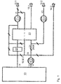
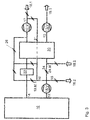
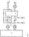
- FIGS. 1 to 4 four embodiments of inventive ventilation equipment are schematically outlined in their air duct.
- Each of these four room ventilation devices is provided for the cooling of a data center 10.
- a first main flow path 17 is formed between the outside air port 18. 1 and the supply air port 14.
- a second main flow path 15 connects the exhaust port 12 to one of the exhaust ports 16.1, 16.2.
- a single fan 15.V, 17.V is provided in the illustrated embodiments.
- a special feature of the invention is that, according to all four exemplary embodiments, a second outside air connection 18.2, at least one second exhaust air connection 16.2 and at least one third main flow path 13 are provided with a third ventilator 13.V. At least two of the three main flow paths 13, 15, 17 are passed countercurrently through at least one heat recovery 20. In the main flow direction towards the data center 10 of the heat recovery 20, a cooling module 22 is connected downstream.
- the third main flow path 13 connects one of the exhaust air connections 16.1 with one of the outside air connections 18.2.
- a single connection flow path 19 is the first and the second Main flow path 17, 15 interconnecting switchable.
- a mixing flap 19.M.1 known type can be switched.
- the single connecting flow path 19 preferably exclusively directs an air flow from the second 15 into the first main flow path 17.
- the cooling module 22 is preferably designed as a hybrid cooler, so that the air flow flowing through can not only be cooled but alternatively humidified.
- the exhaust air connection 12 can be connected to the first main flow path 17 in direct opposition to the heat recovery 20, immediately connected to the first main flow path 17 in order to be at least partially mixed with the outside air.
- the heat recovery 20 is preferably designed as a one-piece component, not as a coupled heat exchanger in a circulatory system, but particularly preferably as a plate heat exchanger.
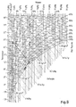
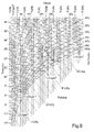
- the inventive method for cooling the data center 10 can be in the FIGS. 1 to 4 and also in the diagrams of FIGS. 5 to 10 comprehend.
- Two main flow paths 13, 15, 17 are passed in countercurrent through the heat recovery 20.
- At least the third main flow path 13 with the third fan 13.V is connected to operate the heat recovery with the supply of outside air and / or exhaust air.
- a second communication flow path 24 connects the second 15 and third main flow paths 13 with each other.
- another mixing flap 24.M of a known type influences the content of outside air in the exhaust air stream guided by the heat recovery 20 by opening the second and third main flow paths 13, 15 more or less to each other.
- the supply air temperature can be regulated by means of a power control of the heat recovery 20, in particular to about 20 ° C.
- a recirculated air portion 21 may be passed through the heat recovery 20 according to an advantageous embodiment of the method, so that the inlet moisture before air treatment does not exceed about 11 g / kg.
- the inlet moisture is measured at the appropriate place and fed to the mixing flap control.
- the speed of at least one of the fans 13.V, 15.V, 17.V can preferably be regulated at least in a first sequence as a function of the return air temperature, in particular in a range between 30 and 100%.
- an outside air mode with mixed operation in a range between about 4 g / kg and 10 g / kg humidity of the supply air can preferably according to the principle of direct free cooling be air-conditioned, wherein particularly preferably in the second sequence circulating air is added.
- the indirect evaporative cooling via outside air 18.2 of the third main flow path 13 is preferably activated, particularly preferably by the exhaust air via the exhaust air fan 15.V of the second main flow path 13 is driven ,
- the exhaust air fan 13.V of the third main flow path 13 is preferably controlled analogously to the circulating air 19 in speed, in particular with the return air pressure or room pressure of the data center 10 as a reference variable.
- the supply air volume flow 17, which is cooled by the heat recovery 20 and the cooling module 22, can preferably be reduced by the amount of the mixed air 19, which is regulated by means of the mixing flap 19.M.1.
- Mollier-hx diagrams are often used in thermodynamics, which show hyperbolic lines of equal relative humidity running from bottom left to top right in 5 to 100% lines above the temperature / humidity field of the air. From top left to bottom right, straight lines of equal enthalpy run in 0 to 60 kJ / kg - lines over this same field. Lines of the same air density proceed with a slight downward gradient from left to right with data in the unit kg / m 3 .
- FIG. 5 is a winter fall with an absolute humidity of less than 4 g / kg registered with arrows.
- an exhaust air with 35 ° C and an outside air with 5 ° C from conditions 1 are mixed.
- FIG. 6 an alternative winter case with an absolute humidity of less than 4 g / kg is shown.
- FIG. 4 guided.
- the outside air of the outside air connection 18.1 is completely driven by the heat recovery 20 (arrow 1) and then moistened as supply air on the way to the data center 10 according to this embodiment of a method according to the invention (arrow 2).
- After moistening and before it enters the data center 10 it is mixed with a partial stream of the exhaust air cooled down after the moistening for reheating.
- the exhaust air 12 is namely passed with closed exhaust port 16.2 through the Ardsströmungsweg 24 through the heat recovery 20.
- FIG. 7 a winter fall at an absolute humidity x greater than 4 g / kg is entered in the hx diagram. In this case, it is not necessary to moisten in an air-conditioning appliance according to the invention.
- a circuit may be utilized at the heat recovery 20 and past the cooling module 22 for the exclusive admixture of exhaust air from the connection flow path 19 into the supply air. It As a result, air that is slightly above 20 ° C enters the data center at slightly less than 40% relative humidity.
- FIG. 8 is a summer case with absolute humidity of the outside air below 10 g / kg shown.
- the exhaust air of the data center 10 is performed with closed Kausströmungsweg 19 and humidification in the heat recovery 20, so that in the heat transfer, an evaporative cooling for cooling the opposite outside air is available.
- the state change of the cooled outside air is registered with the smaller of the two registered arrows, which is directed from top to bottom.
- the absolute humidity of the supply air flow therefore does not change but remains constant at about 9 g / kg.
- the relative humidity of the supply air increases during cooling by about 13% to about 52% relative humidity.
- FIG. 9 is starting from a similar summer case as he according to the circuit FIG. 8 has based, with about 10 g / kg registered an alternative circuit in the hx diagram, after which a cooling in the room ventilation device according to the invention can also be done purely by means of outside air. If you follow this procedure in FIG. 4 After, all connection flow paths 19, 24 must be closed.
- the exhaust fan 15.V then draws the exhaust air from the data center 10 as a first exhaust air 16.2.
- By the supply air fan 17.V passes through the heat recovery 20 led outside air 18.1 past the cooling module 22 as supply air 14 in the data center 10, as a short vertical arrow pointing from top to bottom in Fig. 9 entered. This supply air contrary, as a kinked longer arrow in Fig.
- FIG. 10 In a summer case with higher absolute humidity in the outside air over 10 g / kg is according to FIG. 10 According to the invention, it is preferably cooled by means of humidified outside air 18.2. This humidified outside air is enthalpy-absorbed in the heat transfer.
- the exhaust air 12 from the data center 10 is blown off in a partial flow as exhaust air 16. 2 In a further partial flow exhaust air passes at 35 ° C via the connecting flow 19 again divided into the first main flow path 17.
- a first partial exhaust air flow is in accordance with in FIG. 10 from top left to bottom right arrow 5 with cooled air from the heat recovery 20 with downstream cooling module 22 mixed directly fed as supply air 14 into the data center 10.
- a second partial exhaust air stream is mixed with the incoming into the heat recovery 20 outside air 18.1 to be reduced together in their enthalpy and their temperature (arrows 3 and 4).
Landscapes
- Engineering & Computer Science (AREA)
- Computer Hardware Design (AREA)
- General Engineering & Computer Science (AREA)
- Physics & Mathematics (AREA)
- Thermal Sciences (AREA)
- Microelectronics & Electronic Packaging (AREA)
- Air Conditioning Control Device (AREA)
Applications Claiming Priority (1)
| Application Number | Priority Date | Filing Date | Title |
|---|---|---|---|
| DE102015001845.0A DE102015001845A1 (de) | 2015-02-17 | 2015-02-17 | Raumlufttechnisches Gerät sowie Verfahren zum Kühlen eines Rechenzentrums |
Publications (1)
| Publication Number | Publication Date |
|---|---|
| EP3059511A1 true EP3059511A1 (fr) | 2016-08-24 |
Family
ID=55066417
Family Applications (1)
| Application Number | Title | Priority Date | Filing Date |
|---|---|---|---|
| EP15202809.8A Withdrawn EP3059511A1 (fr) | 2015-02-17 | 2015-12-28 | Appareil de ventilation et procede de refroidissement d'un centre de calcul |
Country Status (2)
| Country | Link |
|---|---|
| EP (1) | EP3059511A1 (fr) |
| DE (1) | DE102015001845A1 (fr) |
Cited By (2)
| Publication number | Priority date | Publication date | Assignee | Title |
|---|---|---|---|---|
| CN109282338A (zh) * | 2018-10-16 | 2019-01-29 | 中国科学院理化技术研究所 | 一种数据中心废热回收系统 |
| CN114025573A (zh) * | 2021-11-10 | 2022-02-08 | 北京字节跳动网络技术有限公司 | 用于数据中心的散热系统及方法 |
Families Citing this family (1)
| Publication number | Priority date | Publication date | Assignee | Title |
|---|---|---|---|---|
| US20210092875A1 (en) | 2017-10-31 | 2021-03-25 | Envion Ag | Mobile data center and method of operating the same |
Citations (5)
| Publication number | Priority date | Publication date | Assignee | Title |
|---|---|---|---|---|
| DE2536124A1 (de) * | 1975-08-13 | 1977-02-17 | Linde Ag | Klimaanlage |
| CA2428409A1 (fr) | 2002-05-10 | 2003-11-10 | Building Performance Equipment, Inc. | Systeme ventilateur et methode |
| DE102004049621A1 (de) * | 2004-10-06 | 2006-04-13 | Hansa Neumann Gmbh | Klimagerät |
| EP2199699A2 (fr) | 2008-12-12 | 2010-06-23 | Mobile Comfort Holding | Installation de climatisation embarquée équipée d`un dispositif thermodynamique de récupération de la chaleur |
| DE102011054257A1 (de) | 2010-10-06 | 2012-04-12 | Dipl.-Ing. Jürgen Loose | Klimagerät |
Family Cites Families (2)
| Publication number | Priority date | Publication date | Assignee | Title |
|---|---|---|---|---|
| DE10106975A1 (de) * | 2001-02-15 | 2002-09-26 | Musial Bjoern Fabian | Luft-Wasser-Wärmepumpe mit Wärmerückgewinnung Zuluftvorerwärmung und Kühlung |
| KR101269287B1 (ko) * | 2011-02-23 | 2013-05-29 | 이동욱 | 열에너지 회수형 환기장치 |
-
2015
- 2015-02-17 DE DE102015001845.0A patent/DE102015001845A1/de not_active Withdrawn
- 2015-12-28 EP EP15202809.8A patent/EP3059511A1/fr not_active Withdrawn
Patent Citations (5)
| Publication number | Priority date | Publication date | Assignee | Title |
|---|---|---|---|---|
| DE2536124A1 (de) * | 1975-08-13 | 1977-02-17 | Linde Ag | Klimaanlage |
| CA2428409A1 (fr) | 2002-05-10 | 2003-11-10 | Building Performance Equipment, Inc. | Systeme ventilateur et methode |
| DE102004049621A1 (de) * | 2004-10-06 | 2006-04-13 | Hansa Neumann Gmbh | Klimagerät |
| EP2199699A2 (fr) | 2008-12-12 | 2010-06-23 | Mobile Comfort Holding | Installation de climatisation embarquée équipée d`un dispositif thermodynamique de récupération de la chaleur |
| DE102011054257A1 (de) | 2010-10-06 | 2012-04-12 | Dipl.-Ing. Jürgen Loose | Klimagerät |
Cited By (3)
| Publication number | Priority date | Publication date | Assignee | Title |
|---|---|---|---|---|
| CN109282338A (zh) * | 2018-10-16 | 2019-01-29 | 中国科学院理化技术研究所 | 一种数据中心废热回收系统 |
| CN114025573A (zh) * | 2021-11-10 | 2022-02-08 | 北京字节跳动网络技术有限公司 | 用于数据中心的散热系统及方法 |
| CN114025573B (zh) * | 2021-11-10 | 2023-03-24 | 抖音视界有限公司 | 用于数据中心的散热系统及方法 |
Also Published As
| Publication number | Publication date |
|---|---|
| DE102015001845A1 (de) | 2016-08-18 |
Similar Documents
| Publication | Publication Date | Title |
|---|---|---|
| EP0127213B1 (fr) | Appareil pour la ventilation et le chauffage des intérieurs, notamment des locaux d'habitation | |
| DE2149548B2 (de) | Klimaanlage für Eisenbahnfahrzeuge | |
| DE102008029922B4 (de) | Raumlufttechnisches Gerät | |
| EP1078854A1 (fr) | Dispositif de climatisation d'avion pour le transport de passagers | |
| EP3059511A1 (fr) | Appareil de ventilation et procede de refroidissement d'un centre de calcul | |
| EP0294730B1 (fr) | Dispositif aéraulique | |
| DE102004049621A1 (de) | Klimagerät | |
| DE102011050323B3 (de) | Kühlvorrichtung zur Klimatisierung einer Datenverarbeitungsanlage | |
| DE4419440C2 (de) | Verfahren und Vorrichtung zum Konditionieren von Luft | |
| WO2018068879A1 (fr) | Aérateur de grands locaux et salles | |
| EP0294729B1 (fr) | Dispositif aéraulique | |
| EP2397805B1 (fr) | Dispositif de refroidissement pour thermophores et composés de l'industrie du froid et pour refroidir les liquides ainsi que pour la récupération du froid en aération | |
| EP3173704A2 (fr) | Installation de ventilation comprenant au moins un echangeur thermique a paroi de separation et procede de recuperation de chaleur a l'aide de surfaces d'echange fixes | |
| CH660910A5 (de) | Verfahren zum durchfluten eines von einer wandung umgebenen raumes mit einem gas. | |
| DE2324262A1 (de) | Klimaanlage | |
| DE3004073A1 (de) | Raumlueftungseinrichtung | |
| DE102017202250A1 (de) | Klimagerät | |
| DE2316030A1 (de) | Klimaanlage. zusatz zu 2212356 | |
| WO2014012897A2 (fr) | Système de climatisation | |
| EP2450204A2 (fr) | Climatisation pour un véhicule automobile | |
| DE3007950A1 (de) | Windkanal | |
| DE3023268C2 (de) | Lüftungsvorrichtung für Werkshallen | |
| DE1454653B2 (de) | Klimaanlage | |
| DE2340264A1 (de) | Klimageraet zur entfeuchtung von raeumen, insbesondere von hallenbaedern | |
| EP3159618B1 (fr) | Dispositif de commutation et de mélange, installation de climatisation et méthode de conception d'une installation de climatisation |
Legal Events
| Date | Code | Title | Description |
|---|---|---|---|
| PUAI | Public reference made under article 153(3) epc to a published international application that has entered the european phase |
Free format text: ORIGINAL CODE: 0009012 |
|
| AK | Designated contracting states |
Kind code of ref document: A1 Designated state(s): AL AT BE BG CH CY CZ DE DK EE ES FI FR GB GR HR HU IE IS IT LI LT LU LV MC MK MT NL NO PL PT RO RS SE SI SK SM TR |
|
| AX | Request for extension of the european patent |
Extension state: BA ME |
|
| 17P | Request for examination filed |
Effective date: 20170224 |
|
| RBV | Designated contracting states (corrected) |
Designated state(s): AL AT BE BG CH CY CZ DE DK EE ES FI FR GB GR HR HU IE IS IT LI LT LU LV MC MK MT NL NO PL PT RO RS SE SI SK SM TR |
|
| 17Q | First examination report despatched |
Effective date: 20170714 |
|
| STAA | Information on the status of an ep patent application or granted ep patent |
Free format text: STATUS: THE APPLICATION HAS BEEN WITHDRAWN |
|
| 18W | Application withdrawn |
Effective date: 20170825 |