EP3059511A1 - Ventilation device and method for cooling a computing center - Google Patents
Ventilation device and method for cooling a computing center Download PDFInfo
- Publication number
- EP3059511A1 EP3059511A1 EP15202809.8A EP15202809A EP3059511A1 EP 3059511 A1 EP3059511 A1 EP 3059511A1 EP 15202809 A EP15202809 A EP 15202809A EP 3059511 A1 EP3059511 A1 EP 3059511A1
- Authority
- EP
- European Patent Office
- Prior art keywords
- air
- main flow
- flow path
- heat recovery
- exhaust
- Prior art date
- Legal status (The legal status is an assumption and is not a legal conclusion. Google has not performed a legal analysis and makes no representation as to the accuracy of the status listed.)
- Withdrawn
Links
Images


Classifications
-
- H—ELECTRICITY
- H05—ELECTRIC TECHNIQUES NOT OTHERWISE PROVIDED FOR
- H05K—PRINTED CIRCUITS; CASINGS OR CONSTRUCTIONAL DETAILS OF ELECTRIC APPARATUS; MANUFACTURE OF ASSEMBLAGES OF ELECTRICAL COMPONENTS
- H05K7/00—Constructional details common to different types of electric apparatus
- H05K7/20—Modifications to facilitate cooling, ventilating, or heating
- H05K7/20709—Modifications to facilitate cooling, ventilating, or heating for server racks or cabinets; for data centers, e.g. 19-inch computer racks
- H05K7/20718—Forced ventilation of a gaseous coolant
- H05K7/20745—Forced ventilation of a gaseous coolant within rooms for removing heat from cabinets, e.g. by air conditioning device
-
- H—ELECTRICITY
- H05—ELECTRIC TECHNIQUES NOT OTHERWISE PROVIDED FOR
- H05K—PRINTED CIRCUITS; CASINGS OR CONSTRUCTIONAL DETAILS OF ELECTRIC APPARATUS; MANUFACTURE OF ASSEMBLAGES OF ELECTRICAL COMPONENTS
- H05K7/00—Constructional details common to different types of electric apparatus
- H05K7/20—Modifications to facilitate cooling, ventilating, or heating
- H05K7/20709—Modifications to facilitate cooling, ventilating, or heating for server racks or cabinets; for data centers, e.g. 19-inch computer racks
- H05K7/20836—Thermal management, e.g. server temperature control
Definitions
- the invention relates to a room air technical device and a method for cooling a data center, with at least one exhaust air, at least one exhaust air and at least one outside air connection, with a first main flow path between the at least one outside air connection and the at least one supply air connection and a second main flow path between the at least one exhaust air connection and the at least one exhaust air connection and with a cooling module, wherein in each of the first and second main flow path a fan is provided according to the preambles of claims 1 and 5 respectively.
- Air handling equipment and such methods may, for example DE 10 2011 054 257 A1 .
- EP 2 199 699 A2 or CA 2 428 409 A1 be removed.
- the present invention has for its object to develop a cost-effective room ventilation device or cooling method that allows a more flexible air treatment for changing needs due to changes in outside air conditions.
- At least one second outside air connection, at least one second exhaust air connection and at least one third main flow path with a third fan are provided, wherein at least two main flow paths are conducted countercurrently by at least one heat recovery.
- At least two of the three main flow paths are passed in countercurrent through the heat recovery.
- At least the third main flow path operates with the third fan, the heat recovery with the supply of outside air and / or exhaust air.
- any system of heat recovery can be used, for example, a plate heat exchanger.
- No circuit interconnection system is needed because the heat recovery of the invention need not be spatially distributed, for example, in either a recirculating air flow path or in a bypass flow path.
- the more flexible circuit according to the invention results in an increased cooling potential, because the recooler can be used independently of the exhaust air flow. According to the invention, either the exhaust air can be guided by the heat recovery or the outside air or a mixture of two air streams.
- a recirculated air portion is first conducted in the direction of the first flow path towards the outside air connection and passed after mixing with outside air with the same by the heat recovery, so that the inlet moisture before air treatment does not exceed about 11 g / kg.
- This example of one of the subclaims is one of the variants of the method according to the invention, which illustrate the flexibility gained when the inventive ventilation equipment can be controlled according to the invention in dependence of the measurement of absolute humidity x in g / kg and temperature of the outside air.
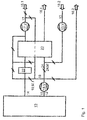
- FIGS. 1 to 4 four embodiments of inventive ventilation equipment are schematically outlined in their air duct.
- Each of these four room ventilation devices is provided for the cooling of a data center 10.
- a first main flow path 17 is formed between the outside air port 18. 1 and the supply air port 14.
- a second main flow path 15 connects the exhaust port 12 to one of the exhaust ports 16.1, 16.2.
- a single fan 15.V, 17.V is provided in the illustrated embodiments.
- a special feature of the invention is that, according to all four exemplary embodiments, a second outside air connection 18.2, at least one second exhaust air connection 16.2 and at least one third main flow path 13 are provided with a third ventilator 13.V. At least two of the three main flow paths 13, 15, 17 are passed countercurrently through at least one heat recovery 20. In the main flow direction towards the data center 10 of the heat recovery 20, a cooling module 22 is connected downstream.
- the third main flow path 13 connects one of the exhaust air connections 16.1 with one of the outside air connections 18.2.
- a single connection flow path 19 is the first and the second Main flow path 17, 15 interconnecting switchable.
- a mixing flap 19.M.1 known type can be switched.
- the single connecting flow path 19 preferably exclusively directs an air flow from the second 15 into the first main flow path 17.
- the cooling module 22 is preferably designed as a hybrid cooler, so that the air flow flowing through can not only be cooled but alternatively humidified.
- the exhaust air connection 12 can be connected to the first main flow path 17 in direct opposition to the heat recovery 20, immediately connected to the first main flow path 17 in order to be at least partially mixed with the outside air.
- the heat recovery 20 is preferably designed as a one-piece component, not as a coupled heat exchanger in a circulatory system, but particularly preferably as a plate heat exchanger.
- the inventive method for cooling the data center 10 can be in the FIGS. 1 to 4 and also in the diagrams of FIGS. 5 to 10 comprehend.
- Two main flow paths 13, 15, 17 are passed in countercurrent through the heat recovery 20.
- At least the third main flow path 13 with the third fan 13.V is connected to operate the heat recovery with the supply of outside air and / or exhaust air.
- a second communication flow path 24 connects the second 15 and third main flow paths 13 with each other.
- another mixing flap 24.M of a known type influences the content of outside air in the exhaust air stream guided by the heat recovery 20 by opening the second and third main flow paths 13, 15 more or less to each other.
- the supply air temperature can be regulated by means of a power control of the heat recovery 20, in particular to about 20 ° C.
- a recirculated air portion 21 may be passed through the heat recovery 20 according to an advantageous embodiment of the method, so that the inlet moisture before air treatment does not exceed about 11 g / kg.
- the inlet moisture is measured at the appropriate place and fed to the mixing flap control.
- the speed of at least one of the fans 13.V, 15.V, 17.V can preferably be regulated at least in a first sequence as a function of the return air temperature, in particular in a range between 30 and 100%.
- an outside air mode with mixed operation in a range between about 4 g / kg and 10 g / kg humidity of the supply air can preferably according to the principle of direct free cooling be air-conditioned, wherein particularly preferably in the second sequence circulating air is added.
- the indirect evaporative cooling via outside air 18.2 of the third main flow path 13 is preferably activated, particularly preferably by the exhaust air via the exhaust air fan 15.V of the second main flow path 13 is driven ,
- the exhaust air fan 13.V of the third main flow path 13 is preferably controlled analogously to the circulating air 19 in speed, in particular with the return air pressure or room pressure of the data center 10 as a reference variable.
- the supply air volume flow 17, which is cooled by the heat recovery 20 and the cooling module 22, can preferably be reduced by the amount of the mixed air 19, which is regulated by means of the mixing flap 19.M.1.
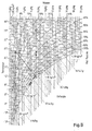
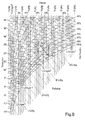
- Mollier-hx diagrams are often used in thermodynamics, which show hyperbolic lines of equal relative humidity running from bottom left to top right in 5 to 100% lines above the temperature / humidity field of the air. From top left to bottom right, straight lines of equal enthalpy run in 0 to 60 kJ / kg - lines over this same field. Lines of the same air density proceed with a slight downward gradient from left to right with data in the unit kg / m 3 .
- FIG. 5 is a winter fall with an absolute humidity of less than 4 g / kg registered with arrows.
- an exhaust air with 35 ° C and an outside air with 5 ° C from conditions 1 are mixed.
- FIG. 6 an alternative winter case with an absolute humidity of less than 4 g / kg is shown.
- FIG. 4 guided.
- the outside air of the outside air connection 18.1 is completely driven by the heat recovery 20 (arrow 1) and then moistened as supply air on the way to the data center 10 according to this embodiment of a method according to the invention (arrow 2).
- After moistening and before it enters the data center 10 it is mixed with a partial stream of the exhaust air cooled down after the moistening for reheating.
- the exhaust air 12 is namely passed with closed exhaust port 16.2 through the Ardsströmungsweg 24 through the heat recovery 20.
- FIG. 7 a winter fall at an absolute humidity x greater than 4 g / kg is entered in the hx diagram. In this case, it is not necessary to moisten in an air-conditioning appliance according to the invention.
- a circuit may be utilized at the heat recovery 20 and past the cooling module 22 for the exclusive admixture of exhaust air from the connection flow path 19 into the supply air. It As a result, air that is slightly above 20 ° C enters the data center at slightly less than 40% relative humidity.
- FIG. 8 is a summer case with absolute humidity of the outside air below 10 g / kg shown.
- the exhaust air of the data center 10 is performed with closed Kausströmungsweg 19 and humidification in the heat recovery 20, so that in the heat transfer, an evaporative cooling for cooling the opposite outside air is available.
- the state change of the cooled outside air is registered with the smaller of the two registered arrows, which is directed from top to bottom.
- the absolute humidity of the supply air flow therefore does not change but remains constant at about 9 g / kg.
- the relative humidity of the supply air increases during cooling by about 13% to about 52% relative humidity.
- FIG. 9 is starting from a similar summer case as he according to the circuit FIG. 8 has based, with about 10 g / kg registered an alternative circuit in the hx diagram, after which a cooling in the room ventilation device according to the invention can also be done purely by means of outside air. If you follow this procedure in FIG. 4 After, all connection flow paths 19, 24 must be closed.
- the exhaust fan 15.V then draws the exhaust air from the data center 10 as a first exhaust air 16.2.
- By the supply air fan 17.V passes through the heat recovery 20 led outside air 18.1 past the cooling module 22 as supply air 14 in the data center 10, as a short vertical arrow pointing from top to bottom in Fig. 9 entered. This supply air contrary, as a kinked longer arrow in Fig.
- FIG. 10 In a summer case with higher absolute humidity in the outside air over 10 g / kg is according to FIG. 10 According to the invention, it is preferably cooled by means of humidified outside air 18.2. This humidified outside air is enthalpy-absorbed in the heat transfer.
- the exhaust air 12 from the data center 10 is blown off in a partial flow as exhaust air 16. 2 In a further partial flow exhaust air passes at 35 ° C via the connecting flow 19 again divided into the first main flow path 17.
- a first partial exhaust air flow is in accordance with in FIG. 10 from top left to bottom right arrow 5 with cooled air from the heat recovery 20 with downstream cooling module 22 mixed directly fed as supply air 14 into the data center 10.
- a second partial exhaust air stream is mixed with the incoming into the heat recovery 20 outside air 18.1 to be reduced together in their enthalpy and their temperature (arrows 3 and 4).
Abstract
Die Erfindung betrifft ein raumlufttechnisches Gerät, insbesondere für die Kühlung eines Rechenzentrums (10), mit zumindest einem Abluft- (12), zumindest einem Zuluft- (14), zumindest einem Fortluft- (16.1, 16.2) und zumindest einem Außenluftanschluss (18.1, 18.2), mit einem ersten Hauptströmungsweg (17) zwischen dem zumindest einen Außenluftanschluss (18.1) und dem zumindest einen Zuluftanschluss (14) und einem zweiten Hauptströmungsweg (15) zwischen dem zumindest einen Abluftanschluss (12) und dem zumindest einen Fortluftanschluss (16.1, 16.2) und mit einem Kühlmodul (22), wobei in dem ersten (17) und dem zweiten Hauptströmungsweg (15) je ein Ventilator (15.V, 17.V) vorgesehen ist. Die Erfindung betrifft ferner ein Verfahren zur Kühlung eines Rechenzentrums (10). Erfindungsgemäß sind zumindest ein zweiter Außenluftanschluss (18.2), zumindest ein zweiter Fortluftanschluss (16.2) und zumindest ein dritter Hauptströmungsweg (13) mit einem dritten Ventilator (13.V) vorgesehen, wobei zumindest zwei Hauptströmungswege (13, 15, 17) im Gegenstrom durch zumindest eine Wärmerückgewinnung (20) geleitet sind.The invention relates to a room air technical device, in particular for cooling a data center (10), with at least one exhaust air (12), at least one Zuluft- (14), at least one exhaust air (16.1, 16.2) and at least one outdoor air connection (18.1, 18.2), with a first main flow path (17) between the at least one outside air connection (18.1) and the at least one supply air connection (14) and a second main flow path (15) between the at least one exhaust air connection (12) and the at least one exhaust air connection (16.1, 16.2 ) and with a cooling module (22), wherein in each of the first (17) and the second main flow path (15) a fan (15.V, 17.V) is provided. The invention further relates to a method for cooling a data center (10). According to the invention, at least one second outside air connection (18.2), at least one second exhaust air connection (16.2) and at least one third main flow path (13) are provided with a third fan (13.V), wherein at least two main flow paths (13, 15, 17) countercurrently through at least one heat recovery (20) are passed.
Description
Die Erfindung betrifft ein raumlufttechnische Gerät und ein Verfahren zum Kühlen eines Rechenzentrums, mit zumindest einem Abluft-, zumindest einem Zuluft-, zumindest einem Fortluft- und zumindest einem Außenluftanschluss, mit einem ersten Hauptströmungsweg zwischen dem zumindest einen Außenluftanschluss und dem zumindest einen Zuluftanschluss und einem zweiten Hauptströmungsweg zwischen dem zumindest einen Abluftanschluss und dem zumindest einen Fortluftanschluss und mit einem Kühlmodul, wobei in dem ersten und dem zweiten Hauptströmungsweg je ein Ventilator vorgesehen ist, gemäß den Oberbegriffen der Ansprüche 1 beziehungsweise 5.The invention relates to a room air technical device and a method for cooling a data center, with at least one exhaust air, at least one exhaust air and at least one outside air connection, with a first main flow path between the at least one outside air connection and the at least one supply air connection and a second main flow path between the at least one exhaust air connection and the at least one exhaust air connection and with a cooling module, wherein in each of the first and second main flow path a fan is provided according to the preambles of
Raumlufttechnische Geräte und solche Verfahren können beispielsweise
Je nach Luftfeuchte- und -temperaturverhältnissen erscheinen bekannte Systeme immer noch zu unflexibel bzw. für nachfolgend beschriebene Lösungswege ungeeignet.Depending on the humidity and temperature conditions, known systems still seem too inflexible or unsuitable for the solutions described below.
Der vorliegenden Erfindung liegt die Aufgabe zugrunde, ein kostengünstig betreibbares raumlufttechnisches Gerät oder Kühlverfahren zu entwickeln, das eine flexiblere Luftbehandlung nach wechselnden Erforderlichkeiten wegen Veränderungen der Außenluftverhältnisse gestattet.The present invention has for its object to develop a cost-effective room ventilation device or cooling method that allows a more flexible air treatment for changing needs due to changes in outside air conditions.
Diese Aufgabe wird mittels eines raumlufttechnischen Geräts und eines Verfahrens aufweisend die kennzeichnenden Merkmale des Anspruchs 1 beziehungsweise des Anspruchs 5 in Verbindung mit den jeweiligen Oberbegriffsmerkmalen gelöst.This object is achieved by means of a ventilation device and a method having the characterizing features of claim 1 or claim 5 solved in conjunction with the respective preamble features.
Weitere vorteilhafte Ausgestaltungen der Erfindung bilden die Gegenstände weiterer Ansprüche.Further advantageous embodiments of the invention form the subject of further claims.
Erfindungsgemäß sind zumindest ein zweiter Außenluftanschluss, zumindest ein zweiter Fortluftanschluss und zumindest ein dritter Hauptströmungsweg mit einem dritten Ventilator vorgesehen, wobei zumindest zwei Hauptströmungswege im Gegenstrom durch zumindest eine Wärmerückgewinnung geleitet sind.According to the invention, at least one second outside air connection, at least one second exhaust air connection and at least one third main flow path with a third fan are provided, wherein at least two main flow paths are conducted countercurrently by at least one heat recovery.
Gemäß dem erfindungsgemäßen Verfahren werden zumindest zwei der drei Hauptströmungswege im Gegenstrom durch die Wärmerückgewinnung geleitet. Zumindest der dritte Hauptströmungsweg betreibt dabei mit dem dritten Ventilator die Wärmerückgewinnung mit der Zufuhr von Außenluft und / oder Abluft.According to the inventive method at least two of the three main flow paths are passed in countercurrent through the heat recovery. At least the third main flow path operates with the third fan, the heat recovery with the supply of outside air and / or exhaust air.
Als Erfolg der erfindungsgemäßen Lösung kann jedes beliebige System der Wärmerückgewinnung genutzt werden, beispielsweise ein Plattenwärmeübertrager. Es wird kein Kreislaufverbundsystem benötigt, weil die Wärmerückgewinnung gemäß der Erfindung nicht örtlich verteilt, beispielsweise entweder in einem Umluftströmungsweg oder in einem Bypass-Strömungsweg, angeordnet sein muss. Konnte bei solchen bekannten raumlufttechnischen Geräten bisher eine als Rückkühler betriebene Wärmerückgewinnung im Fortluftstrom nicht unabhängig von der Außenluft und/oder der Abluft betrieben werden, da sich bei bekannten raumlufttechnischen Geräten bei einem geforderten Mindestaußenluftanteil zwingend ein Mischpunkt aus beiden Luftvolumenströmen vor der Wärmerückgewinnung einstellt, gelingt das bei erfindungsgemäßer Verfahrensweise eben doch. Daher bleibt nun eine bisherige Konzentration auf den Mischpunkt vor der Fortluft-Wärmerückgewinnung nicht als einzige Möglichkeit für den Fall, dass ein Mindestaußenluftanteil zum Erreichen energetisch optimaler Bedingungen gefahren werden muss.As the success of the solution according to the invention, any system of heat recovery can be used, for example, a plate heat exchanger. No circuit interconnection system is needed because the heat recovery of the invention need not be spatially distributed, for example, in either a recirculating air flow path or in a bypass flow path. Could not be operated independently of the outside air and / or the exhaust air in such a known room air handling equipment operated as a recooler heat recovery in the exhaust air flow, as in known room ventilation equipment at a required minimum outside air necessarily a mixing point of the two air flow before Heat recovery adjusts, but succeeds in the inventive method just yet. Therefore, a previous focus on the mixing point before the exhaust air heat recovery is not the only option in the event that a minimum external air content must be driven to achieve optimal energy conditions.
Die flexiblere Schaltung gemäß der Erfindung ergibt ein gesteigertes Kühlpotenzial, weil der Rückkühler unabhängig von dem Abluftstrom genutzt werden kann. Erfindungsgemäß kann entweder die Abluft durch die Wärmerückgewinnung geführt werden oder die Außenluft oder eine Mischung aus beiden Luftströmen.The more flexible circuit according to the invention results in an increased cooling potential, because the recooler can be used independently of the exhaust air flow. According to the invention, either the exhaust air can be guided by the heat recovery or the outside air or a mixture of two air streams.
Gemäß einer vorteilhaften Ausführungsform des Verfahrens wird ein Umluftanteil zunächst in Richtung des ersten Strömungswegs Richtung Außenluftanschluss geführt und nach Mischung mit Außenluft mit derselben durch die Wärmerückgewinnung geleitet, sodass die Eintrittsfeuchte vor der Luftbehandlung etwa 11 g/kg nicht überschreitet.According to an advantageous embodiment of the method, a recirculated air portion is first conducted in the direction of the first flow path towards the outside air connection and passed after mixing with outside air with the same by the heat recovery, so that the inlet moisture before air treatment does not exceed about 11 g / kg.
Dieses Beispiel aus einem der Unteransprüche ist eine der erfindungsgemäßen Verfahrensvarianten, welche die gewonnene Flexibilität verdeutlichen, wenn die erfindungsgemäßen raumlufttechnischen Geräte sich erfindungsgemäß in Abhängigkeit der Messung von absoluter Feuchte x in g/kg und Temperatur der Außenluft regeln lassen.This example of one of the subclaims is one of the variants of the method according to the invention, which illustrate the flexibility gained when the inventive ventilation equipment can be controlled according to the invention in dependence of the measurement of absolute humidity x in g / kg and temperature of the outside air.
Zur Verdeutlichung der Erfindung sind in den nachfolgend beschriebenen Figuren Ausführungsbeispiele angegeben. Es zeigen:
- Fig. 1
- ein erstes Ausführungsbeispiel eines erfindungsgemäßen raumlufttechnischen Geräts mit zwei Außenluftventilatoren und einem Abluftventilator in schematischer Darstellung,
- Fig. 2
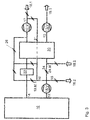
- ein zweites Ausführungsbeispiel eines erfindungsgemäßen raumlufttechnischen Geräts mit zwei Fortluftventilatoren und einem Zuluftventilator in schematischer Darstellung,
- Fig. 3
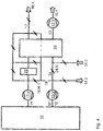
- ein drittes Ausführungsbeispiel eines erfindungsgemäßen raumlufttechnischen Geräts mit einem Außenluftventilator, einem Fortluftventilator und einem Abluftventilator in schematischer Darstellung,
- Fig. 4
- ein viertes Ausführungsbeispiel eines erfindungsgemäßen raumlufttechnischen Geräts mit einem Zuluftventilator, einem Fortluftventilator und einem Abluftventilator in schematischer Darstellung,
- Fig. 5
- ein erstes Mollier-h-x-Diagramm für feuchte Luft,
- Fig. 6
- ein alternativ zum ersten Mollier-h-x-Diagramm der
Fig. 5 , in das ein alternativer Winterfall dargestellt ist, - Fig. 7
- ein drittes Mollier-h-x-Diagramm für feuchte Luft,
- Fig. 8
- ein viertes Mollier-h-x-Diagramm für feuchte Luft,
- Fig. 9
- ein fünftes Mollier-h-x-Diagramm für feuchte Luft und
- Fig. 10
- ein sechstes Mollier-h-x-Diagramm für feuchte Luft.
- Fig. 1
- a first embodiment of a room ventilation device according to the invention with two Outside air fans and an exhaust fan in a schematic representation,
- Fig. 2
- A second embodiment of an inventive room ventilation device with two exhaust fans and a supply air fan in a schematic representation,
- Fig. 3
- A third embodiment of a room ventilation device according to the invention with an outside air fan, an exhaust air fan and an exhaust fan in a schematic representation,
- Fig. 4
- A fourth embodiment of an air-conditioning device according to the invention with a supply air fan, an exhaust air fan and an exhaust fan in a schematic representation,
- Fig. 5
- a first Mollier-hx diagram for humid air,
- Fig. 6
- an alternative to the first Mollier-hx diagram of
Fig. 5 , in which an alternative winter case is shown, - Fig. 7
- a third Mollier-hx diagram for humid air,
- Fig. 8
- a fourth Mollier-hx diagram for humid air,
- Fig. 9
- a fifth Mollier-hx diagram for humid air and
- Fig. 10
- a sixth Mollier-hx diagram for humid air.
In den
Jedes dieser vier raumlufttechnischen Geräte ist für die Kühlung eines Rechenzentrums 10 vorgesehen.Each of these four room ventilation devices is provided for the cooling of a
Grundsätzlich weisen sie auf: zumindest einen Abluft- 12, zumindest einen Zuluft- 14, zumindest zwei Fortluft- 16.1, 16.2 und zumindest zwei Außenluftanschluss/-anschlüsse 18.1, 18.2. Ein erster Hauptströmungsweg 17 ist zwischen dem Außenluftanschluss 18.1 und dem Zuluftanschluss 14 ausgebildet. Ein zweiter Hauptströmungsweg 15 verbindet den Abluftanschluss 12 mit einem der Fortluftanschlüsse 16.1, 16.2. In dem ersten 17 und dem zweiten Hauptströmungsweg 15 ist in den dargestellten Ausführungsbeispielen je ein einziger Ventilator 15.V, 17.V vorgesehen.In principle, they have at least one
Eine Besonderheit der Erfindung liegt darin, dass gemäß allen vier Ausführungsbeispielen ein zweiter Außenluftanschluss 18.2, zumindest ein zweiter Fortluftanschluss 16.2 und zumindest ein dritter Hauptströmungsweg 13 mit einem dritten Ventilator 13.V vorgesehen sind. Dabei sind zumindest zwei der drei Hauptströmungswege 13, 15, 17 im Gegenstrom durch zumindest eine Wärmerückgewinnung 20 geleitet. In Hauptströmungsrichtung Richtung Rechenzentrum 10 ist der Wärmerückgewinnung 20 ein Kühlmodul 22 nachgeschaltet.A special feature of the invention is that, according to all four exemplary embodiments, a second outside air connection 18.2, at least one second exhaust air connection 16.2 and at least one third
Gemäß den Ausführungsbeispielen der
Dabei leitet der einzige Verbindungsströmungsweg 19 bevorzugt ausschließlich einen Luftstrom vom zweiten 15 in den ersten Hauptströmungsweg 17.In this case, the single connecting
Das Kühlmodul 22 ist bevorzugt als ein Hybridkühler ausgeführt, sodass der durchströmende Luftstrom nicht nur gekühlt sondern alternativ befeuchtet werden kann.The
In einem Umluftbetriebszustand kann der Abluftanschluss 12 dem ersten Hauptströmungsweg 17 entgegen die Wärmerückgewinnung 20 umgehend 21 geführt mit dem ersten Hauptströmungsweg 17 verbunden werden, um mit der Außenluft zumindest teilweise gemischt zu werden.In a recirculating air operating state, the
Die Wärmerückgewinnung 20 ist bevorzugt als ein einteiliges Bauelement ausgeführt, nicht etwa als ein gekoppelter Wärmeübertrager in einem Kreislaufverbundsystem, sondern besonders bevorzugt als ein Plattenwärmeübertrager.The
Auch das erfindungsgemäße Verfahren zum Kühlen des Rechenzentrums 10 lässt sich in den
Dabei wird bevorzugt eines der vorangehend beschriebenen erfindungsgemäßen raumlufttechnischen Geräte verwendet.In this case, preference is given to using one of the above-described room ventilation devices according to the invention.
Bevorzugt verbindet ein zweiter Verbindungsströmungsweg 24 den zweiten 15 und dritten Hauptströmungsweg 13 miteinander. Dabei beeinflusst eine weitere Mischklappe 24.M bekannter Art den Gehalt an Außenluft in dem durch die Wärmerückgewinnung 20 geleiteten Abluftstrom, indem sie den zweiten und dritten Hauptströmungsweg 13, 15 mehr oder weniger zueinander öffnet.Preferably, a second
In einem Übergangsbetrieb kann die Zulufttemperatur mittels einer Leistungsregelung der Wärmerückgewinnung 20 geregelt werden, insbesondere auf etwa 20°C.In a transient mode, the supply air temperature can be regulated by means of a power control of the
Ein Umluftanteil 21 kann gemäß einer vorteilhaften Ausführungsform des Verfahrens durch die Wärmerückgewinnung 20 geleitet werden, sodass die Eintrittsfeuchte vor der Luftbehandlung etwa 11 g/kg nicht überschreitet. Dazu wird die Eintrittsfeuchte an entsprechender Stelle gemessen und der Mischklappenregelung zugeführt.A recirculated
In einem Außenluftbetrieb kann bevorzugt die Drehzahl zumindest eines der Ventilatoren 13.V, 15.V, 17.V zumindest in einer ersten Sequenz in Abhängigkeit der Rücklufttemperatur geregelt werden, insbesondere in einem Bereich zwischen 30 und 100 %.In an outside air mode, the speed of at least one of the fans 13.V, 15.V, 17.V can preferably be regulated at least in a first sequence as a function of the return air temperature, in particular in a range between 30 and 100%.
In einem Außenluftbetrieb mit Mischbetrieb in einem Bereich etwa zwischen 4 g/kg und 10 g/kg Feuchte der Zuluft kann bevorzugt nach dem Prinzip der direkten freien Kühlung klimatisiert werden, wobei besonders bevorzugt in zweiter Sequenz Umluft beigemischt wird.In an outside air mode with mixed operation in a range between about 4 g / kg and 10 g / kg humidity of the supply air can preferably according to the principle of direct free cooling be air-conditioned, wherein particularly preferably in the second sequence circulating air is added.
Beim Erreichen der maximalen direkten freien Kühlleistung und im Fall eines Überschreitens der Rückluft-Kühlgrenztemperatur über das Außenluftniveau wird bevorzugt die indirekte Verdunstungskühlung über Außenluft 18.2 des dritten Hauptströmungswegs 13 aktiviert, besonders bevorzugt indem die Abluft über den Fortluftventilator 15.V des zweiten Hauptströmungswegs 13 gefahren wird.Upon reaching the maximum direct free cooling capacity and in the event of exceeding the return air cooling temperature limit above the outside air level, the indirect evaporative cooling via outside air 18.2 of the third
Der Fortluftventilator 13.V des dritten Hauptströmungsweges 13 wird bevorzugt analog zum Umluftanteil 19 in der Drehzahl geregelt, insbesondere mit dem Rückluftdruck oder Raumdruck des Rechenzentrums 10 als Führungsgröße.The exhaust air fan 13.V of the third
Der Zuluftvolumenstrom 17, der über die Wärmerückgewinnung 20 und das Kühlmodul 22 gekühlt wird, kann bevorzugt um den Betrag der Mischluft 19 reduziert werden, der mittels der Mischklappe 19.M.1 geregelt wird.The supply
In den
In
In
In
In
In
In einem Sommerfall bei höherer absoluter Feuchte in der Außenluft über 10 g/kg wird gemäß
Die Abluft 12 aus dem Rechenzentrum 10 wird in einem Teilstrom als Fortluft 16. 2 abgeblasen. In einem weiteren Teilstrom gelangt Abluft mit 35 °C über den Verbindungsströmungsweg 19 wiederum geteilt in den ersten Hauptströmungsweg 17. Ein erster Teilabluftstrom wird gemäß in
- 1010
- RechenzentrumData Center
- 1212
- Abluftanschlussexhaust connection
- 1313
- dritter Hauptströmungswegthird main flow path
- 13.V13.V
- Ventilatorfan
- 1414
- Zuluftanschlusssupply air
- 1515
- zweiter Hauptströmungswegsecond main flow path
- 15.V15.V
- Ventilatorfan
- 16.116.1
- FortluftanschlussExhaust air connection
- 16.216.2
- FortluftanschlussExhaust air connection
- 1717
- erster Hauptströmungswegfirst main flow path
- 17.V17.V
- Ventilatorfan
- 18.118.1
- AußenluftanschlussOutside air connection
- 18.218.2
- AußenluftanschlussOutside air connection
- 1919
- Verbindungsströmungswegcommunication flow
- 2020
- WärmerückgewinnungHeat recovery
- 2121
- separate Gegenstromführungseparate countercurrent flow
- 2222
- Kühlmodulcooling module
- 2424
- zweiter Verbindungsströmungswegsecond connection flow path
- 24.M24.M
- zweite Mischklappesecond mixing flap
Claims (14)
dadurch gekennzeichnet, dass das Kühlmodul (22) als Hybridkühler ausgeführt ist, sodass der durchströmende Luftstrom nicht nur gekühlt sondern alternativ befeuchtet werden kann.Air-conditioning device according to claim 1,
characterized in that the cooling module (22) is designed as a hybrid cooler, so that the air flow flowing through can not only be cooled but alternatively moistened.
dadurch gekennzeichnet, dass in einem Umluftbetriebszustand der Abluftanschluss (12) dem ersten Hauptströmungsweg (17) entgegen (21) die Wärmerückgewinnung (20) umgehend geführt mit dem ersten Hauptströmungsweg (17) verbunden ist, um mit der Außenluft zumindest teilweise gemischt zu werden.Ventilation apparatus according to one of the preceding claims,
characterized in that in a Umluftbetriebszustand the exhaust port (12) the first main flow path (17) opposite (21) the heat recovery (20) promptly guided to the first main flow path (17) is connected to be at least partially mixed with the outside air.
dadurch gekennzeichnet, dass die Wärmerückgewinnung (20) als ein einteiliges Bauelement ausgeführt ist, nicht etwa als ein gekoppelter Wärmeübertrager (Kreislaufverbundsystem), sondern insbesondere als ein Plattenwärmeübertrager.Ventilation apparatus according to one of the preceding claims,
characterized in that the heat recovery (20) is designed as a one-piece component, not as a coupled heat exchanger (circulatory system), but in particular as a plate heat exchanger.
wobei
zwei Hauptströmungswege (13, 15, 17) im Gegenstrom durch die Wärmerückgewinnung (20) geleitet werden,
dadurch gekennzeichnet, dass zumindest der dritte Hauptströmungsweg (13) mit dem dritten Ventilator (13.V) geschaltet ist, um die Wärmerückgewinnung (20) mit der Zufuhr von Außenluft und / oder Abluft zu betreiben.A method of conditioning a data center (10) having at least three main flow paths (13, 15, 17) between exhaust air (12), supply air (14), exhaust air (16.1, 16.2) and outdoor air connections (18.1, 18.2), each main flowpath (13, 15, 17) at least one fan (13.V, 15.V, 17.V), further comprising a cooling module (22), a heat recovery (20) and a connection flow path (19) for connecting at least two main flow paths ( 15, 17),
in which
two main flow paths (13, 15, 17) are passed in countercurrent through the heat recovery (20),
characterized in that at least the third main flow path (13) is connected to the third fan (13.V) to operate the heat recovery (20) with the supply of outside air and / or exhaust air.
dadurch gekennzeichnet, dass ein Raumlufttechnisches Gerät nach einem der Ansprüche 1 bis 4 verwendet wird.Method according to claim 5,
characterized in that an air-conditioning device according to one of claims 1 to 4 is used.
dadurch gekennzeichnet, dass ein zweiter Verbindungsströmungsweg (24) den zweiten (15) und dritten Hauptströmungsweg (13) miteinander verbindet, wobei eine Mischklappe (24.M) den Gehalt an Außenluft in dem durch die Wärmerückgewinnung (20) geleiteten Abluftstrom beeinflusst, indem sie den zweiten und dritten Hauptströmungsweg (13, 15) mehr oder weniger zueinander öffnet.Method according to one of claims 5 or 6,
characterized in that a second connection flow path (24) interconnects the second (15) and third main flow paths (13), wherein a mixing flap (24.M) influences the content of outside air in the exhaust air flow passed through the heat recovery (20) the second and third main flow paths (13, 15) opens more or less to each other.
dadurch gekennzeichnet, dass in einem Übergangsbetrieb die Zulufttemperatur mittels der Leistungsregelung der Wärmerückgewinnung (20) geregelt wird, insbesondere auf etwa 20°C.Method according to one of claims 5 to 7,
characterized in that in a transitional operation, the supply air temperature is controlled by means of the power control of the heat recovery (20), in particular to about 20 ° C.
dadurch gekennzeichnet, dass ein Umluftanteil (21) durch die Wärmerückgewinnung (20) geleitet wird, sodass die Eintrittsfeuchte vor der Luftbehandlung etwa 11 g/kg nicht überschreitet.Method according to claim 8,
characterized in that a recirculated air portion (21) by the heat recovery (20) so that the inlet moisture before air treatment does not exceed about 11 g / kg.
dadurch gekennzeichnet, dass in einem Außenluftbetrieb die Drehzahl zumindest eines der Ventilatoren (13.V, 15.V, 17.V) zumindest in einer ersten Sequenz in Abhängigkeit der Rücklufttemperatur geregelt wird, insbesondere in einem Bereich zwischen 30 und 100 %.Method according to one of claims 5 to 9,
characterized in that in an outside air operation, the speed of at least one of the fans (13.V, 15.V, 17.V) is controlled at least in a first sequence depending on the return air temperature, in particular in a range between 30 and 100%.
dadurch gekennzeichnet, dass in einem Außenluftbetrieb mit Mischbetrieb ebenfalls in einem Bereich etwa zwischen 4 g/kg und 10 g/kg Feuchte der Zuluft nach dem Prinzip der direkten freien Kühlung klimatisiert wird, wobei bevorzugt in zweiter Sequenz Umluft beigemischt wird.Method according to one of claims 5 to 10,
characterized in that in an outdoor air mode with mixed operation also in a range of about 4 g / kg and 10 g / kg humidity of the supply air is conditioned according to the principle of direct free cooling, preferably in the second sequence circulating air is added.
dadurch gekennzeichnet, dass beim Erreichen der maximalen direkten freien Kühlleistung und im Fall eines Überschreitens der Rückluft-Kühlgrenztemperatur über das Außenluftniveau die indirekte Verdunstungskühlung über Außenluft (18.2) des dritten Hauptströmungswegs (13) aktiviert wird und indem die Abluft über den Fortluftventilator (15.V) des zweiten Hauptströmungswegs (13) gefahren wird.Method according to one of claims 5 to 11,
characterized in that upon reaching the maximum direct free cooling capacity and in case of exceeding the return air cooling temperature above the outside air level, the indirect evaporative cooling via outside air (18.2) of the third main flow path (13) is activated and by the exhaust air via the exhaust air fan (15.V ) of the second main flow path (13).
dadurch gekennzeichnet, dass der Fortluftventilator (13.V) des dritten Hauptströmungsweges (13) analog zum Umluftanteil (19) in der Drehzahl geregelt wird, insbesondere mit Führungsgröße Rückluftdruck oder Raumdruck des Rechenzentrums (10).Method according to one of claims 5 to 12,
characterized in that the exhaust air fan (13.V) of the third main flow path (13) analogous to the recirculated air portion (19) is controlled in the speed, in particular with reference variable return air pressure or room pressure of the data center (10).
dadurch gekennzeichnet, dass der Zuluftvolumenstrom (17), der über die Wärmerückgewinnung (20) und das Kühlmodul (22) gekühlt wird, um den Betrag der Mischluft (19) reduziert wird, der mittels einer weiteren Mischklappe (19.M.1) geregelt wird.Method according to one of claims 5 to 13,
characterized in that the supply air volume flow (17), which is cooled by the heat recovery (20) and the cooling module (22), by the amount of the mixed air (19) is reduced by means of another mixing flap (19.M.1) regulated becomes.
Applications Claiming Priority (1)
| Application Number | Priority Date | Filing Date | Title |
|---|---|---|---|
| DE102015001845.0A DE102015001845A1 (en) | 2015-02-17 | 2015-02-17 | Air-conditioning device and method for cooling a data center |
Publications (1)
| Publication Number | Publication Date |
|---|---|
| EP3059511A1 true EP3059511A1 (en) | 2016-08-24 |
Family
ID=55066417
Family Applications (1)
| Application Number | Title | Priority Date | Filing Date |
|---|---|---|---|
| EP15202809.8A Withdrawn EP3059511A1 (en) | 2015-02-17 | 2015-12-28 | Ventilation device and method for cooling a computing center |
Country Status (2)
| Country | Link |
|---|---|
| EP (1) | EP3059511A1 (en) |
| DE (1) | DE102015001845A1 (en) |
Cited By (2)
| Publication number | Priority date | Publication date | Assignee | Title |
|---|---|---|---|---|
| CN109282338A (en) * | 2018-10-16 | 2019-01-29 | 中国科学院理化技术研究所 | A kind of data center's Waste Heat Recovery System |
| CN114025573A (en) * | 2021-11-10 | 2022-02-08 | 北京字节跳动网络技术有限公司 | Heat dissipation system and method for data center |
Families Citing this family (1)
| Publication number | Priority date | Publication date | Assignee | Title |
|---|---|---|---|---|
| EP3704561A1 (en) | 2017-10-31 | 2020-09-09 | Hellmann-Regen, Julian | Mobile data center and method of operating the same |
Citations (5)
| Publication number | Priority date | Publication date | Assignee | Title |
|---|---|---|---|---|
| DE2536124A1 (en) * | 1975-08-13 | 1977-02-17 | Linde Ag | Air conditioning device for rooms - has branch pipe from air input channel with condenser of cooling plant situated within |
| CA2428409A1 (en) | 2002-05-10 | 2003-11-10 | Building Performance Equipment, Inc. | Ventilator system and method |
| DE102004049621A1 (en) * | 2004-10-06 | 2006-04-13 | Hansa Neumann Gmbh | Air conditioning system has unit for adiabatic cooling of at least part of air flows, unit for transmission of thermal energy and/or moisture between flow paths, and flap valves to control air flows |
| EP2199699A2 (en) | 2008-12-12 | 2010-06-23 | Mobile Comfort Holding | On-vehicle air-conditioning installaton with a thermodynamical device for heat recovery |
| DE102011054257A1 (en) | 2010-10-06 | 2012-04-12 | Dipl.-Ing. Jürgen Loose | air conditioning |
Family Cites Families (2)
| Publication number | Priority date | Publication date | Assignee | Title |
|---|---|---|---|---|
| DE10106975A1 (en) * | 2001-02-15 | 2002-09-26 | Musial Bjoern Fabian | Air-water heat pump with heat recovery, supply air preheating and cooling |
| KR101269287B1 (en) * | 2011-02-23 | 2013-05-29 | 이동욱 | Thermal energy collection ventilator |
-
2015
- 2015-02-17 DE DE102015001845.0A patent/DE102015001845A1/en not_active Withdrawn
- 2015-12-28 EP EP15202809.8A patent/EP3059511A1/en not_active Withdrawn
Patent Citations (5)
| Publication number | Priority date | Publication date | Assignee | Title |
|---|---|---|---|---|
| DE2536124A1 (en) * | 1975-08-13 | 1977-02-17 | Linde Ag | Air conditioning device for rooms - has branch pipe from air input channel with condenser of cooling plant situated within |
| CA2428409A1 (en) | 2002-05-10 | 2003-11-10 | Building Performance Equipment, Inc. | Ventilator system and method |
| DE102004049621A1 (en) * | 2004-10-06 | 2006-04-13 | Hansa Neumann Gmbh | Air conditioning system has unit for adiabatic cooling of at least part of air flows, unit for transmission of thermal energy and/or moisture between flow paths, and flap valves to control air flows |
| EP2199699A2 (en) | 2008-12-12 | 2010-06-23 | Mobile Comfort Holding | On-vehicle air-conditioning installaton with a thermodynamical device for heat recovery |
| DE102011054257A1 (en) | 2010-10-06 | 2012-04-12 | Dipl.-Ing. Jürgen Loose | air conditioning |
Cited By (3)
| Publication number | Priority date | Publication date | Assignee | Title |
|---|---|---|---|---|
| CN109282338A (en) * | 2018-10-16 | 2019-01-29 | 中国科学院理化技术研究所 | A kind of data center's Waste Heat Recovery System |
| CN114025573A (en) * | 2021-11-10 | 2022-02-08 | 北京字节跳动网络技术有限公司 | Heat dissipation system and method for data center |
| CN114025573B (en) * | 2021-11-10 | 2023-03-24 | 抖音视界有限公司 | Heat dissipation system and method for data center |
Also Published As
| Publication number | Publication date |
|---|---|
| DE102015001845A1 (en) | 2016-08-18 |
Similar Documents
| Publication | Publication Date | Title |
|---|---|---|
| EP0127213B1 (en) | Apparatus for ventilating and heating interior spaces, particularly living rooms | |
| DE2149548B2 (en) | Air conditioning for railway vehicles | |
| DE102008029922B4 (en) | Air conditioning device | |
| EP1078854A1 (en) | Device for air-conditioning of passenger aircraft | |
| EP3059511A1 (en) | Ventilation device and method for cooling a computing center | |
| DE4318255A1 (en) | Air conditioner for vehicle interior with drive producing waste heat - contains refrigerant and separate hot liquid circulation systems which can be coupled with unit across at least one heat exchanger. | |
| EP0294730B1 (en) | Ventilation device | |
| DE102004049621A1 (en) | Air conditioning system has unit for adiabatic cooling of at least part of air flows, unit for transmission of thermal energy and/or moisture between flow paths, and flap valves to control air flows | |
| DE102011050323B3 (en) | Cooling device for data processing system, has pressure chamber which is separated by boundary wall from heat exchanger such that overpressure is obtained in pressure chamber in operation of fan assembly | |
| DE4419440C2 (en) | Air conditioning method and apparatus | |
| WO2018068879A1 (en) | Ventilator for large rooms and halls | |
| EP0294729B1 (en) | Ventilation device | |
| EP3173704A2 (en) | Ventilation assembly with at least one division heat exchanger and recuperative method for recovering heat with solid exchange surfaces | |
| CH660910A5 (en) | Method for floods of a wall of an area surrounded with a gas. | |
| DE2324262A1 (en) | AIR CONDITIONER | |
| DE3004073A1 (en) | Ventilation equipment for room - has high-pressure fan supplying room air to secondary air ejector nozzles | |
| DE102017202250A1 (en) | air conditioning | |
| DE2316030A1 (en) | AIR CONDITIONER. ADDITIONAL TO 2212356 | |
| EP2450204A2 (en) | Air conditioning for a motor vehicle | |
| DE3007950A1 (en) | Wind tunnel with low power air conditioner - operating in branch channel with slower flow than main feed, and enabling heating, cooling, humidifying and drying functions | |
| DE3023268C2 (en) | Ventilation device for factory halls | |
| DE1454653B2 (en) | air conditioning | |
| DE2340264A1 (en) | Swimming-baths de-humidifying air-conditioner - with condenser behind compressor flooded by water carrying away heat content | |
| EP3159618B1 (en) | Switching and mixing device, indoor air treatment system and design method for an indoor air treatment system | |
| DE1604160C3 (en) | Air conditioning for automobiles |
Legal Events
| Date | Code | Title | Description |
|---|---|---|---|
| PUAI | Public reference made under article 153(3) epc to a published international application that has entered the european phase |
Free format text: ORIGINAL CODE: 0009012 |
|
| AK | Designated contracting states |
Kind code of ref document: A1 Designated state(s): AL AT BE BG CH CY CZ DE DK EE ES FI FR GB GR HR HU IE IS IT LI LT LU LV MC MK MT NL NO PL PT RO RS SE SI SK SM TR |
|
| AX | Request for extension of the european patent |
Extension state: BA ME |
|
| 17P | Request for examination filed |
Effective date: 20170224 |
|
| RBV | Designated contracting states (corrected) |
Designated state(s): AL AT BE BG CH CY CZ DE DK EE ES FI FR GB GR HR HU IE IS IT LI LT LU LV MC MK MT NL NO PL PT RO RS SE SI SK SM TR |
|
| 17Q | First examination report despatched |
Effective date: 20170714 |
|
| STAA | Information on the status of an ep patent application or granted ep patent |
Free format text: STATUS: THE APPLICATION HAS BEEN WITHDRAWN |
|
| 18W | Application withdrawn |
Effective date: 20170825 |