EP3058856B1 - Multifunction cooking device - Google Patents
Multifunction cooking device Download PDFInfo
- Publication number
- EP3058856B1 EP3058856B1 EP16155628.7A EP16155628A EP3058856B1 EP 3058856 B1 EP3058856 B1 EP 3058856B1 EP 16155628 A EP16155628 A EP 16155628A EP 3058856 B1 EP3058856 B1 EP 3058856B1
- Authority
- EP
- European Patent Office
- Prior art keywords
- cooking
- surrounding wall
- wall portion
- multifunction
- cooking surface
- Prior art date
- Legal status (The legal status is an assumption and is not a legal conclusion. Google has not performed a legal analysis and makes no representation as to the accuracy of the status listed.)
- Active
Links
Images





Classifications
-
- A—HUMAN NECESSITIES
- A47—FURNITURE; DOMESTIC ARTICLES OR APPLIANCES; COFFEE MILLS; SPICE MILLS; SUCTION CLEANERS IN GENERAL
- A47J—KITCHEN EQUIPMENT; COFFEE MILLS; SPICE MILLS; APPARATUS FOR MAKING BEVERAGES
- A47J37/00—Baking; Roasting; Grilling; Frying
- A47J37/06—Roasters; Grills; Sandwich grills
- A47J37/0611—Roasters; Grills; Sandwich grills the food being cooked between two heating plates, e.g. waffle-irons
Definitions
- the disclosure relates to a cooking device, and more particularly to a multifunction cooking device.
- a conventional cooking device has a base unit 12 and a cover unit 11 connected to each other, a shallow pan 13 removably disposed between the cover and base units 11, 12, and a deep pan 14 removably disposed between the cover and base units 11, 12.
- the base unit 12 includes a base seat 121.
- the cover unit 11 includes a cover seat 111 and a cover plate 112 disposed on the cover seat 111.
- the shallow pan 13 can be used for grilling food.
- the deep pan 14 has a bottom wall 141 and a surrounding wall 142 extending upwardly from the bottom wall 141.
- the bottom and surrounding walls 141, 142 cooperatively define a cooking space 143.
- the cooking space 143 can be used for stir-frying food or cooking a sauce.
- the conventional cooking device is changeable between first and second states.
- the cover unit 11 In the first state, the cover unit 11 is located in close proximity to the base unit 12, the shallow pan 13 is disposed on the base unit 12, and the cover plate 112 abuts against the shallow pan 13.
- the cover unit 11 In the second state, the cover unit 11 is located distal from the base unit 12, the deep pan 14 is disposed on the base unit 12, and the cover plate 112 abuts against a top end of the surrounding wall 142 of the deep pan 14.
- the conventional cooking device can have cooking functions of stir-frying, grilling, boiling, etc.
- the conventional cooking device can only accommodate or store one of the shallow and deep pans 13, 14, so that the other one of the shallow and deep pans 13, 14 has to be stored separately, thereby occupying a substantial space.
- US 3 719 507 A relates to a cooking appliance in which a cover section having a lower heat-conductive grilling surface overlies a base section presenting an upper heat-conductive grilling surface, the opposed surfaces being contoured such that they are adapted to mate in overlying relation to define an upper internal cavity for the reception of an article of food to be cooked draining downwardly peripherally through a narrow passage formation into a lower surrounding channel formation open to the atmosphere.
- EP 2 965 673 A1 provides an inexpensive electric cooker in which a different-height upper or lower die is properly mounted without necessity of replacing a hinge or upper and lower housings or of manufacturing an electric cooker exclusively used for each baked product.
- the electric cooker comprises a lower housing ; a lower die mounted on the lower housing; an upper housing pivotally mounted at the rear end via a hinge shaft to the lower housing to turn upward from the lower housing upward; an upper die mounted on the upper housing, a lower surface of the upper die being capable of being disposed in an upper surface of the lower die; an electric heater disposed in at least one of the lower housing and upper housing and heating at least one of the lower die and the upper die from back to heat dough for bread or the like between the lower die and the upper die; and hinge-shaft height adjusting means changing a vertical position of the upper housing pivotally mounted via the hinge shaft by adjusting height of the hinge shaft.
- JP 5 662 624 B1 It is an object of the disclosure to provide a multifunction cooking device that can alleviate the drawback of the prior art.
- the multifunction cooking device includes a base unit, a cooking pan and a cover unit.
- the base unit includes a base seat that defines an annular receiving space, and a heating unit disposed in the base seat and surrounded by the annular receiving space.
- the cooking pan is disposed on the base unit and includes a bottom wall contacting with the heating unit, and a surrounding wall transversely extending from the bottom wall and inserted into the annular receiving space.
- the cover unit is movably connected to the base unit and covers the cooking pan.
- said bottom wall of said cooking pan has opposite first and second cooking surfaces, said surrounding wall having a first surrounding wall portion extending from a periphery of said first cooking surface in a direction away from said second cooking surface, and a second surrounding wall portion extending from a periphery of said second cooking surface in a direction away from said first cooking surface; and said second surrounding wall portion has a height H 1 extending from said second cooking surface smaller than a height H 2 of said first surrounding wall portion extending from said first cooking surface.
- a multifunction cooking device 100 includes a cooking pan 2, a base unit 3, a cover unit 4, and a connection unit 5.
- the cooking pan 2 is disposed between the base unit 3 and the cover unit 4 (see Figure 6 ), and includes a pan body 6 and a scald-preventing frame 7.
- the pan body 6 has a bottom wall 61 and a surrounding wall 62 transversely extending from the bottom wall 61 .
- the bottom wall 61 has opposite first and second cooking surfaces 611, 612.
- the second cooking surface 612 has a plurality of spaced-apart ribs 613.
- the surrounding wall 62 has a first surrounding wall portion 621 extending from a periphery of the first cooking surface 611 in a direction away from the second cooking surface 612, and a second surrounding wall portion 622 extending from a periphery of the second cooking surface 612 in a direction away from the first cooking surface 611.
- the first surrounding wall portion 621 has a distal end 623 distal from the first cooking surface 611, and cooperates with the first cooking surface 611 to define a cooking space 63. Further, the first surrounding wall portion 621 extends outwardly and inclinedly from the bottom wall 61.
- the second surrounding wall portion 622 has a height (H 1 ) that extends from the second cooking surface 612 smaller than a height (H 2 ) of the first surrounding wall portion 621 extending from the first cooking surface 611 and that is about one-fifth of the height (H 2 ) of the first surrounding portion 621.
- the second surrounding wall portion 622 and the second cooking surface 612 cooperatively define a grilling space 64.
- the scald-preventing frame 7 is disposed on an outer periphery of the surrounding wall 62, and includes an annular flange 71 that extends horizontally and that has an inner periphery connected to an outer periphery of the second surrounding wall portion 622, an upright wall 72 that extends transversely from the annular flange 71 in a direction similar to that of the first surrounding wall portion 621, and two grip members 73 provided on two opposite sides of the annular flange 71 for gripping by a user.
- the upright wall 72 has a first wall portion 722 that is connected to the annular flange 71 at a position proximate to the outer periphery of the second surrounding wall portion 622 and that is spaced apart from the first surrounding wall portion 621, and a second wall portion 721 having one end connected to the first wall portion 722 and the other end connected to the distal end 623 of the first surrounding wall portion 621.
- the upright wall 72, the annular flange 71 and the surrounding wall 62 cooperatively define a heat-insulating space 8.
- the scald-preventing frame 7 can effectively prevent a user from being scalded, thereby enhancing safety and reliability of use of the present disclosure.
- the base unit 3 includes a base seat 31 and a heating unit 32.
- the base seat 31 has inner and outer surrounding walls 312, 311 connected to each other at bottom ends thereof and cooperatively defining an annular receiving space 33 therebetween.
- the heating unit 32 is disposed in the base seat 31, and is surrounded by the annular receiving space 33.
- the cover unit 4 is movably connected to the base unit 31, and includes a cover seat 41 and a cover plate 42 disposed on a bottom of the cover seat 41.
- the cover plate 42 is larger than the cooking pan 2, and removably covers and surrounds the cooking pan 2. Specifically, when the cover plate 42 covers the cooking pan 2, the distal end 623 of the first surrounding wall portion 621 is covered and surrounded by the cover plate 42, as shown in Figure 6 , or a distal end of the second surrounding wall portion 622 is covered and surrounded by the cover plate 42, as shown in Figure 9 .
- connection unit 5 interconnects the cover unit 4 and the base unit 3, and can position the cover unit 4 relative to the base unit 3.
- the connection unit 5 includes two spaced-apart connecting rods 51 having lower ends 511 respectively pivoted to two opposite sides of the base seat 31 at a rear end thereof, upper ends 512 opposite to the lower ends 511, and intermediate portions 513 each connected between one of the lower ends 511 and a corresponding upper end 512.
- the pull rod 52 is connected between the upper ends 512 of the connecting rods 51.
- the cover seat 41 is connected between the intermediate portions 513 of the pull rods 51. The user can grip the pull rod 52 to move the cover unit 4 away from the base unit 3 to facilitate changing of the multifunction cooking device 100 from a first state to a second state, and vice versa.
- the cover unit 4 In the first state, as shown in Figure 6 , the cover unit 4 is located in close proximity to the base unit 3.
- the cover unit 4 is located distal from the base unit 3.
- the first cooking surface 611 of the cooking pan 2 is first disposed to face downward, after which the first surrounding wall portion 621 is inserted into the annular receiving space 33, thereby completing the assembly of the cooking pan 2 and the base unit 3, as shown in Figure 7 .
- the food to be grilled (not shown) is placed on the second cooking surface 612 of the cooking pan 2, and the pull rod 52 is pulled to move the cover unit 4 downward to thereby place the multifunction cooking device 100 in the first state (see Figure 6 ) .
- the first cooking surface 611 contacts with the heating unit 32 to transmit heat to the second cooking surface 612, and the cover plate 42 of the cover unit 4 abuts against the distal end of the second surrounding wall portion 622 to cooperate with the second cooking surface 612 to grill the food (not shown) in the grilling space 64.
- the second cooking surface 612 of the cooking pan 2 is first disposed to face downward, after which the second surrounding wall portion 622 is inserted into the annular receiving space 33, thereby completing the assembly of the cooking pan 2 and the base unit 3, as shown in Figure 10 .
- the ingredients (not shown) for cooking the sauce, soup or stew are placed on the first cooking surface 611 of the cooking pan 2, and the pull rod 52 is pulled to move the cover unit 4 downward to thereby place the multifunction cooking device 100 in the second state (see Figure 9 ) .
- the second cooking surface 612 contacts with the heating unit 32 to transmit heat to the first cooking surface 611, and the cover plate 42 of the cover unit 4 abuts against the distal end 623 of the first surrounding wall portion 621 to cover the cooking space 63. Due to the height (H 2 ) of the first surrounding wall portion 621 being greater than the height (H 1 ) of the second surrounding wall portion 622, the cooking space 63 defined by the first surrounding wall portion 621 and the first cooking surface 611 is deeper than the grilling space 64 defined by the second surrounding wall portion 622 and the second cooking surface 612, so that the sauce, soup or stew can be cooked in the cooking space 63.
- the multifunction cooking device 100 of the present disclosure can resolve the storage problem encountered in the prior art.
Landscapes
- Engineering & Computer Science (AREA)
- Food Science & Technology (AREA)
- Baking, Grill, Roasting (AREA)
Description
- The disclosure relates to a cooking device, and more particularly to a multifunction cooking device.
- Referring to
Figures 1 and2 , a conventional cooking device has abase unit 12 and acover unit 11 connected to each other, ashallow pan 13 removably disposed between the cover andbase units deep pan 14 removably disposed between the cover andbase units - The
base unit 12 includes abase seat 121. Thecover unit 11 includes acover seat 111 and acover plate 112 disposed on thecover seat 111. Theshallow pan 13 can be used for grilling food. Thedeep pan 14 has abottom wall 141 and a surroundingwall 142 extending upwardly from thebottom wall 141. The bottom and surroundingwalls cooking space 143. Thecooking space 143 can be used for stir-frying food or cooking a sauce. - The conventional cooking device is changeable between first and second states. In the first state, the
cover unit 11 is located in close proximity to thebase unit 12, theshallow pan 13 is disposed on thebase unit 12, and thecover plate 112 abuts against theshallow pan 13. In the second state, thecover unit 11 is located distal from thebase unit 12, thedeep pan 14 is disposed on thebase unit 12, and thecover plate 112 abuts against a top end of the surroundingwall 142 of thedeep pan 14. - By virtue of the shallow and
deep pans deep pans deep pans -
US 3 719 507 A relates to a cooking appliance in which a cover section having a lower heat-conductive grilling surface overlies a base section presenting an upper heat-conductive grilling surface, the opposed surfaces being contoured such that they are adapted to mate in overlying relation to define an upper internal cavity for the reception of an article of food to be cooked draining downwardly peripherally through a narrow passage formation into a lower surrounding channel formation open to the atmosphere. -
EP 2 965 673 A1 - The same applies for
JP 5 662 624 B1
It is an object of the disclosure to provide a multifunction cooking device that can alleviate the drawback of the prior art. - According to the disclosure, the multifunction cooking device includes a base unit, a cooking pan and a cover unit. The base unit includes a base seat that defines an annular receiving space, and a heating unit disposed in the base seat and surrounded by the annular receiving space. The cooking pan is disposed on the base unit and includes a bottom wall contacting with the heating unit, and a surrounding wall transversely extending from the bottom wall and inserted into the annular receiving space. The cover unit is movably connected to the base unit and covers the cooking pan. Further said bottom wall of said cooking pan has opposite first and second cooking surfaces, said surrounding wall having a first surrounding wall portion extending from a periphery of said first cooking surface in a direction away from said second cooking surface, and a second surrounding wall portion extending from a periphery of said second cooking surface in a direction away from said first cooking surface; and said second surrounding wall portion has a height H1 extending from said second cooking surface smaller than a height H2 of said first surrounding wall portion extending from said first cooking surface.
- Other features and advantages of the disclosure will become apparent in the following detailed description of the embodiment with reference to the accompanying drawings, of which:
-
Figure 1 is a partly sectional view of a conventional cooking device in a first state; -
Figure 2 is a partly sectional view of the conventional cooking device in a second state; -
Figure 3 is a perspective view of a cooking pan of a multifunction cooking device according to an embodiment of the present disclosure; -
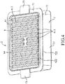
Figure 4 is another perspective view of the cooking pan of the embodiment; -
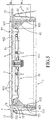
Figure 5 is an assembled sectional view of the cooking pan and a base unit of the embodiment with a second cooking surface facing upwardly; -
Figure 6 is a side view of the embodiment, illustrating the multifunction cooking device in a first state; -
Figure 7 is a perspective view of the embodiment, illustrating a cover unit of the multifunction cooking device in an opened position and the second cooking surface of the cooking pan facing upwardly; -
Figure 8 is another assembled sectional view of the cooking pan and the base unit of the embodiment with a first cooking surface of the cooking pan facing upwardly; -
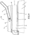
Figure 9 is another side view of the embodiment, illustrating the multifunction cooking device in a second state; and -
Figure 10 is a view similar toFigure 7 , but illustrating the first cooking surface of the cooking pan facing upwardly. - A
multifunction cooking device 100 according to an embodiment of the present disclosure includes acooking pan 2, abase unit 3, acover unit 4, and aconnection unit 5. - Referring to
Figures 3 to 5 , thecooking pan 2 is disposed between thebase unit 3 and the cover unit 4 (seeFigure 6 ), and includes apan body 6 and a scald-preventingframe 7. - The
pan body 6 has abottom wall 61 and a surroundingwall 62 transversely extending from thebottom wall 61 . Thebottom wall 61 has opposite first andsecond cooking surfaces second cooking surface 612 has a plurality of spaced-apart ribs 613. The surroundingwall 62 has a first surroundingwall portion 621 extending from a periphery of thefirst cooking surface 611 in a direction away from thesecond cooking surface 612, and a second surroundingwall portion 622 extending from a periphery of thesecond cooking surface 612 in a direction away from thefirst cooking surface 611. The first surroundingwall portion 621 has adistal end 623 distal from thefirst cooking surface 611, and cooperates with thefirst cooking surface 611 to define acooking space 63. Further, the first surroundingwall portion 621 extends outwardly and inclinedly from thebottom wall 61. The second surroundingwall portion 622 has a height (H1) that extends from thesecond cooking surface 612 smaller than a height (H2) of the first surroundingwall portion 621 extending from thefirst cooking surface 611 and that is about one-fifth of the height (H2) of the first surroundingportion 621. In addition, the second surroundingwall portion 622 and thesecond cooking surface 612 cooperatively define agrilling space 64. - The scald-preventing
frame 7 is disposed on an outer periphery of the surroundingwall 62, and includes anannular flange 71 that extends horizontally and that has an inner periphery connected to an outer periphery of the second surroundingwall portion 622, anupright wall 72 that extends transversely from theannular flange 71 in a direction similar to that of the first surroundingwall portion 621, and twogrip members 73 provided on two opposite sides of theannular flange 71 for gripping by a user. Theupright wall 72 has afirst wall portion 722 that is connected to theannular flange 71 at a position proximate to the outer periphery of the second surroundingwall portion 622 and that is spaced apart from the first surroundingwall portion 621, and asecond wall portion 721 having one end connected to thefirst wall portion 722 and the other end connected to thedistal end 623 of the first surroundingwall portion 621. Theupright wall 72, theannular flange 71 and the surroundingwall 62 cooperatively define a heat-insulatingspace 8. Since the contact area between the scald-preventingframe 7 and thepan body 6 is small, and the heat-insulatingspace 8 is capable of preventing heat transmission from thepan body 6 to the scald-preventingframe 7, the scald-preventingframe 7 can effectively prevent a user from being scalded, thereby enhancing safety and reliability of use of the present disclosure. - Referring to
Figures 6 and7 , in combination withFigure 5 , thebase unit 3 includes abase seat 31 and aheating unit 32. Thebase seat 31 has inner and outer surroundingwalls receiving space 33 therebetween. Theheating unit 32 is disposed in thebase seat 31, and is surrounded by theannular receiving space 33. - The
cover unit 4 is movably connected to thebase unit 31, and includes acover seat 41 and acover plate 42 disposed on a bottom of thecover seat 41. Thecover plate 42 is larger than thecooking pan 2, and removably covers and surrounds thecooking pan 2. Specifically, when thecover plate 42 covers thecooking pan 2, thedistal end 623 of the first surroundingwall portion 621 is covered and surrounded by thecover plate 42, as shown inFigure 6 , or a distal end of the second surroundingwall portion 622 is covered and surrounded by thecover plate 42, as shown inFigure 9 . - The
connection unit 5 interconnects thecover unit 4 and thebase unit 3, and can position thecover unit 4 relative to thebase unit 3. Theconnection unit 5 includes two spaced-apart connectingrods 51 havinglower ends 511 respectively pivoted to two opposite sides of thebase seat 31 at a rear end thereof,upper ends 512 opposite to thelower ends 511, andintermediate portions 513 each connected between one of thelower ends 511 and a correspondingupper end 512. Thepull rod 52 is connected between theupper ends 512 of the connectingrods 51. Thecover seat 41 is connected between theintermediate portions 513 of thepull rods 51. The user can grip thepull rod 52 to move thecover unit 4 away from thebase unit 3 to facilitate changing of themultifunction cooking device 100 from a first state to a second state, and vice versa. In the first state, as shown inFigure 6 , thecover unit 4 is located in close proximity to thebase unit 3. In the second state, as shown inFigure 9 , thecover unit 4 is located distal from thebase unit 3. - To use the
multifunction cooking device 100 for grilling, thefirst cooking surface 611 of thecooking pan 2 is first disposed to face downward, after which the first surroundingwall portion 621 is inserted into theannular receiving space 33, thereby completing the assembly of thecooking pan 2 and thebase unit 3, as shown inFigure 7 . Sequentially, the food to be grilled (not shown) is placed on thesecond cooking surface 612 of thecooking pan 2, and thepull rod 52 is pulled to move thecover unit 4 downward to thereby place themultifunction cooking device 100 in the first state (seeFigure 6 ) . In this state, thefirst cooking surface 611 contacts with theheating unit 32 to transmit heat to thesecond cooking surface 612, and thecover plate 42 of thecover unit 4 abuts against the distal end of the second surroundingwall portion 622 to cooperate with thesecond cooking surface 612 to grill the food (not shown) in thegrilling space 64. - Referring to
Figures 8 to 10 , to use themultifunction cooking device 100 for cooking sauce, soup, or stew, thesecond cooking surface 612 of thecooking pan 2 is first disposed to face downward, after which the second surroundingwall portion 622 is inserted into theannular receiving space 33, thereby completing the assembly of thecooking pan 2 and thebase unit 3, as shown inFigure 10 . Sequentially, the ingredients (not shown) for cooking the sauce, soup or stew are placed on thefirst cooking surface 611 of thecooking pan 2, and thepull rod 52 is pulled to move thecover unit 4 downward to thereby place themultifunction cooking device 100 in the second state (seeFigure 9 ) . In this state, thesecond cooking surface 612 contacts with theheating unit 32 to transmit heat to thefirst cooking surface 611, and thecover plate 42 of thecover unit 4 abuts against thedistal end 623 of the first surroundingwall portion 621 to cover thecooking space 63. Due to the height (H2) of the first surroundingwall portion 621 being greater than the height (H1) of the second surroundingwall portion 622, thecooking space 63 defined by the first surroundingwall portion 621 and thefirst cooking surface 611 is deeper than the grillingspace 64 defined by the second surroundingwall portion 622 and thesecond cooking surface 612, so that the sauce, soup or stew can be cooked in thecooking space 63. - To sum up, by virtue of the
annular receiving space 33 defined by the inner and outer surroundingwalls base seat 31, the first or second surroundingwall portion wall 62 can be inserted into theannular receiving space 33 and stored therein, so that there is no need to find a place for storing thecooking pan 2 when not in use. Hence, themultifunction cooking device 100 of the present disclosure can resolve the storage problem encountered in the prior art. - In the description above, for the purposes of explanation, numerous specific details have been set forth in order to provide a thorough understanding of the embodiment. It will be apparent, however, to one skilled in the art, that one or more other embodiments may be practiced without some of these specific details. It should also be appreciated that reference throughout this specification to "one embodiment," "an embodiment," an embodiment with an indication of an ordinal number and so forth means that a particular feature, structure, or characteristic may be included in the practice of the disclosure. It should be further appreciated that in the description, various features are sometimes grouped together in a single embodiment, figure, or description thereof for the purpose of streamlining the disclosure and aiding in the understanding of various inventive aspects.
Claims (9)
- A multifunction cooking device (100) characterized by:a base unit (3) including a base seat (31) that defines an annular receiving space (33), and a heating unit (32) disposed in said base seat (31) and surrounded by said annular receiving space (33);a cooking pan (2) disposed on said base unit (3) and including a bottom wall (61) contacting with said heating unit (32), and a surrounding wall (62) transversely extending from said bottom wall (61) and inserted into said annular receiving space (33); anda cover unit (4) movably connected to said base unit (3) and covering said cooking pan (2);characterized in thatsaid bottom wall (61) of said cooking pan (2) has opposite first and second cooking surfaces (611, 612), said surrounding wall (62) having a first surrounding wall portion (621) extending from a periphery of said first cooking surface (611) in a direction away from said second cooking surface (612), and a second surrounding wall portion (622) extending from a periphery of said second cooking surface (612) in a direction away from said first cooking surface (611); andsaid second surrounding wall portion (622) has a height (H1) extending from said second cooking surface (612) smaller than a height (H2) of said first surrounding wall portion (621) extending from said first cooking surface (611).
- The multifunction cooking device (100) as claimed in Claim 1, characterized in that:said multifunction cooking device (100) is changeable between a first state, where said cover unit (4) is located in close proximity to said base unit (3), and a second state, where said cover unit (4) is located distal from said base unit (3); andwhen said multifunction cooking device (100) is in the first state, said first surrounding wall portion (621) is inserted into said annular receiving space (33), said first cooking surface (611) contacts with said heating unit (32), and said second cooking surface (612) faces said cover unit (4).
- The multifunction cooking device (100) as claimed in Claim 2, characterized in that said second cooking surface (612) has a plurality of spaced-apart ribs (613), and characterized in that, when said multifunction cooking device (100) is in the second state, said second surrounding wall portion (622) is inserted into said annular receiving space (33), said second cooking surface (612) contacts with said heating unit (32), and said first cooking surface (611) faces said cover unit (4).
- The multifunction cooking device (100) as claimed in Claim 2, characterized in that said first surrounding wall portion (621) of said surrounding wall (62) has a distal end (623) distal from said first cooking surface (611), said cooking pan (2) further including a scald-preventing frame (7) disposed on an outer periphery of said surrounding wall (62), said scald-preventing frame (7) including an annular flange (71) that has an inner periphery connected to said surrounding wall (62), and an upright wall (72) that extends transversely from said annular flange (71) in a direction similar to that of said first surrounding wall portion (621), said upright wall (72) having a first wall portion (722) that is connected to said annular flange (71) and that is spaced apart from said surrounding wall (62), and a second wall portion (721) connected to said distal end (623) of said first surrounding wall portion (621).
- The multifunction cooking device (100) as claimed in Claim 4, characterized in that said first surrounding wall portion (621) of said surrounding wall (62) extends outwardly and inclinedly from said bottom wall (61).
- The multifunction cooking device (100) as claimed in Claim 4, characterized in that said scald-preventing frame (7) further includes a plurality of grip members (73) provided on two opposite sides of said annular flange (71).
- The multifunction cooking device (100) as claimed in Claim 4, characterized in that said upright wall (72), said annular flange (71) and said surrounding wall (62) cooperatively define a heat-insulating space (8).
- The multifunction cooking device (100) as claimed in Claim 1, characterized in that said cover unit (4) includes a cover plate (42) that is larger than said cooking pan (2) and that removably covers and surrounds said cooking pan (2).
- The multifunction cooking device (100) as claimed in Claim 1, characterized in that said bottom wall (61) of said cooking pan (2) has opposite first and second cooking surfaces (611, 612), said surrounding wall (62) cooperating with said first cooking surface (611) to define a cooking space (63), said surrounding wall (62) and said second cooking surface (612) cooperatively defining a grilling space, said cooking space (63) being deeper than said grilling space (64).
Applications Claiming Priority (1)
| Application Number | Priority Date | Filing Date | Title |
|---|---|---|---|
| CN201520113878.6U CN204520385U (en) | 2015-02-17 | 2015-02-17 | Grill |
Publications (2)
| Publication Number | Publication Date |
|---|---|
| EP3058856A1 EP3058856A1 (en) | 2016-08-24 |
| EP3058856B1 true EP3058856B1 (en) | 2019-07-17 |
Family
ID=53734453
Family Applications (1)
| Application Number | Title | Priority Date | Filing Date |
|---|---|---|---|
| EP16155628.7A Active EP3058856B1 (en) | 2015-02-17 | 2016-02-15 | Multifunction cooking device |
Country Status (3)
| Country | Link |
|---|---|
| US (1) | US10201246B2 (en) |
| EP (1) | EP3058856B1 (en) |
| CN (1) | CN204520385U (en) |
Families Citing this family (5)
| Publication number | Priority date | Publication date | Assignee | Title |
|---|---|---|---|---|
| CN105231896A (en) * | 2015-11-05 | 2016-01-13 | 周林斌 | Baking tray capable of fixedly forking hamburgers |
| CN107041694B (en) * | 2016-02-05 | 2019-12-24 | 漳州灿坤实业有限公司 | Storage device of food frying and roasting device |
| USD1009560S1 (en) * | 2021-05-05 | 2024-01-02 | Revolution Cooking, Llc | Sandwich press |
| WO2023065644A1 (en) * | 2021-10-22 | 2023-04-27 | 佛山市顺德区美的电热电器制造有限公司 | Cooking appliance |
| CN116138624A (en) * | 2022-09-08 | 2023-05-23 | 漳州立达信光电子科技有限公司 | a cooking utensil |
Family Cites Families (16)
| Publication number | Priority date | Publication date | Assignee | Title |
|---|---|---|---|---|
| US3457852A (en) * | 1967-10-16 | 1969-07-29 | Emily T Y Kwoh | Reversible multiple cooking oven,steamer,grill and griddle |
| US3719507A (en) * | 1971-03-01 | 1973-03-06 | W Bardeau | Cooking appliance |
| US6064042A (en) * | 1999-02-19 | 2000-05-16 | Appliance Development Corporation | Reversible self-contained cooking appliance |
| USD268981S (en) * | 1981-01-09 | 1983-05-17 | Litton Systems, Inc. | Reversible microwave roasting rack |
| US5782165A (en) * | 1992-09-01 | 1998-07-21 | Ever Splendor Enterprises Co., Ltd. | Multi-purpose cooking apparatus |
| US6024014A (en) * | 1999-03-02 | 2000-02-15 | Hiraoka & Co. ( H.K. ) , Ltd. | Portable reversible grill with improved fluid drainage |
| FR2794014B1 (en) * | 1999-05-31 | 2001-07-27 | Seb Sa | MULTI-FUNCTIONAL ELECTRIC KITCHEN APPLIANCE |
| US6389961B1 (en) * | 2001-08-21 | 2002-05-21 | Tsann Kuen Usa Inc | Grill plate |
| US7059318B2 (en) * | 2003-04-24 | 2006-06-13 | Randall Cornfield | Multi-purpose stovetop grilling and cooking device |
| FR2855737B1 (en) * | 2003-06-03 | 2005-07-22 | Seb Sa | REVERSIBLE GRILL FOLLOWING DIFFERENT INCLINATIONS |
| DE602004017315D1 (en) * | 2003-06-30 | 2008-12-04 | Conair | REVERSIBLE COOKER |
| US6782801B1 (en) * | 2003-11-10 | 2004-08-31 | Jose Correa | Stove top barbecue |
| USD538584S1 (en) * | 2006-01-05 | 2007-03-20 | Lodge Manufacturing Company | Square reversible grill pan/griddle |
| US20070277678A1 (en) * | 2006-05-17 | 2007-12-06 | Joy Mangano | Multifunction electric cooker |
| WO2010151642A2 (en) * | 2009-06-24 | 2010-12-29 | Meco Corporation | Collapsible gas grill |
| JP5662624B1 (en) * | 2014-05-27 | 2015-02-04 | 株式会社サンテックコーポレーション | Electric heating cooker |
-
2015
- 2015-02-17 CN CN201520113878.6U patent/CN204520385U/en not_active Expired - Lifetime
-
2016
- 2016-02-08 US US15/018,246 patent/US10201246B2/en active Active
- 2016-02-15 EP EP16155628.7A patent/EP3058856B1/en active Active
Non-Patent Citations (1)
| Title |
|---|
| None * |
Also Published As
| Publication number | Publication date |
|---|---|
| US20160235247A1 (en) | 2016-08-18 |
| CN204520385U (en) | 2015-08-05 |
| US10201246B2 (en) | 2019-02-12 |
| EP3058856A1 (en) | 2016-08-24 |
Similar Documents
| Publication | Publication Date | Title |
|---|---|---|
| EP2976977B1 (en) | Multifunctional cookware | |
| EP2133013B1 (en) | Multi-purpose cooking appliance | |
| EP0696430A1 (en) | Multi-function electric home appliance | |
| KR200448883Y1 (en) | Grill combined use pot of dual structure | |
| US20180192820A1 (en) | Multi level configurable countertop roaster oven | |
| US8042457B2 (en) | Grill with anti-scald structure | |
| US10201246B2 (en) | Multifunction cooking device | |
| CN207520040U (en) | A kind of dual-purpose electric baking pan | |
| CN213155350U (en) | An electric heating pot with improved structure | |
| CN114073421A (en) | Cooking utensil | |
| CN213129090U (en) | A multifunctional electric cooker | |
| JP5711034B2 (en) | Cooking equipment | |
| CN210989820U (en) | Frying and roasting equipment | |
| CN211459870U (en) | Baking tray assembly and baking machine | |
| CN223286958U (en) | Pot components and cooking utensils | |
| KR200479981Y1 (en) | Multi-purpose pot | |
| CN212521548U (en) | Air fryer is with frying bucket subassembly | |
| US12490859B2 (en) | Stuffed waffle utensil | |
| KR102485949B1 (en) | Multipurpose cooker | |
| CN221285478U (en) | Multifunctional food cooking utensil | |
| CN215686648U (en) | Cooking utensil | |
| CN211212717U (en) | Bakeware | |
| KR20070061492A (en) | Multi-purpose cooker using ocher far infrared | |
| JP3424152B2 (en) | Induction heating cooker | |
| CN209107054U (en) | A kind of grill |
Legal Events
| Date | Code | Title | Description |
|---|---|---|---|
| PUAI | Public reference made under article 153(3) epc to a published international application that has entered the european phase |
Free format text: ORIGINAL CODE: 0009012 |
|
| AK | Designated contracting states |
Kind code of ref document: A1 Designated state(s): AL AT BE BG CH CY CZ DE DK EE ES FI FR GB GR HR HU IE IS IT LI LT LU LV MC MK MT NL NO PL PT RO RS SE SI SK SM TR |
|
| AX | Request for extension of the european patent |
Extension state: BA ME |
|
| STAA | Information on the status of an ep patent application or granted ep patent |
Free format text: STATUS: REQUEST FOR EXAMINATION WAS MADE |
|
| 17P | Request for examination filed |
Effective date: 20170223 |
|
| RBV | Designated contracting states (corrected) |
Designated state(s): AL AT BE BG CH CY CZ DE DK EE ES FI FR GB GR HR HU IE IS IT LI LT LU LV MC MK MT NL NO PL PT RO RS SE SI SK SM TR |
|
| GRAP | Despatch of communication of intention to grant a patent |
Free format text: ORIGINAL CODE: EPIDOSNIGR1 |
|
| STAA | Information on the status of an ep patent application or granted ep patent |
Free format text: STATUS: GRANT OF PATENT IS INTENDED |
|
| INTG | Intention to grant announced |
Effective date: 20190213 |
|
| GRAJ | Information related to disapproval of communication of intention to grant by the applicant or resumption of examination proceedings by the epo deleted |
Free format text: ORIGINAL CODE: EPIDOSDIGR1 |
|
| GRAL | Information related to payment of fee for publishing/printing deleted |
Free format text: ORIGINAL CODE: EPIDOSDIGR3 |
|
| STAA | Information on the status of an ep patent application or granted ep patent |
Free format text: STATUS: REQUEST FOR EXAMINATION WAS MADE |
|
| GRAS | Grant fee paid |
Free format text: ORIGINAL CODE: EPIDOSNIGR3 |
|
| GRAR | Information related to intention to grant a patent recorded |
Free format text: ORIGINAL CODE: EPIDOSNIGR71 |
|
| STAA | Information on the status of an ep patent application or granted ep patent |
Free format text: STATUS: GRANT OF PATENT IS INTENDED |
|
| GRAA | (expected) grant |
Free format text: ORIGINAL CODE: 0009210 |
|
| STAA | Information on the status of an ep patent application or granted ep patent |
Free format text: STATUS: THE PATENT HAS BEEN GRANTED |
|
| INTC | Intention to grant announced (deleted) | ||
| AK | Designated contracting states |
Kind code of ref document: B1 Designated state(s): AL AT BE BG CH CY CZ DE DK EE ES FI FR GB GR HR HU IE IS IT LI LT LU LV MC MK MT NL NO PL PT RO RS SE SI SK SM TR |
|
| INTG | Intention to grant announced |
Effective date: 20190607 |
|
| REG | Reference to a national code |
Ref country code: GB Ref legal event code: FG4D |
|
| REG | Reference to a national code |
Ref country code: CH Ref legal event code: EP |
|
| REG | Reference to a national code |
Ref country code: IE Ref legal event code: FG4D |
|
| REG | Reference to a national code |
Ref country code: DE Ref legal event code: R096 Ref document number: 602016016868 Country of ref document: DE |
|
| REG | Reference to a national code |
Ref country code: AT Ref legal event code: REF Ref document number: 1155040 Country of ref document: AT Kind code of ref document: T Effective date: 20190815 |
|
| REG | Reference to a national code |
Ref country code: NL Ref legal event code: MP Effective date: 20190717 |
|
| REG | Reference to a national code |
Ref country code: LT Ref legal event code: MG4D |
|
| REG | Reference to a national code |
Ref country code: AT Ref legal event code: MK05 Ref document number: 1155040 Country of ref document: AT Kind code of ref document: T Effective date: 20190717 |
|
| PG25 | Lapsed in a contracting state [announced via postgrant information from national office to epo] |
Ref country code: NL Free format text: LAPSE BECAUSE OF FAILURE TO SUBMIT A TRANSLATION OF THE DESCRIPTION OR TO PAY THE FEE WITHIN THE PRESCRIBED TIME-LIMIT Effective date: 20190717 Ref country code: PT Free format text: LAPSE BECAUSE OF FAILURE TO SUBMIT A TRANSLATION OF THE DESCRIPTION OR TO PAY THE FEE WITHIN THE PRESCRIBED TIME-LIMIT Effective date: 20191118 Ref country code: BG Free format text: LAPSE BECAUSE OF FAILURE TO SUBMIT A TRANSLATION OF THE DESCRIPTION OR TO PAY THE FEE WITHIN THE PRESCRIBED TIME-LIMIT Effective date: 20191017 Ref country code: LT Free format text: LAPSE BECAUSE OF FAILURE TO SUBMIT A TRANSLATION OF THE DESCRIPTION OR TO PAY THE FEE WITHIN THE PRESCRIBED TIME-LIMIT Effective date: 20190717 Ref country code: HR Free format text: LAPSE BECAUSE OF FAILURE TO SUBMIT A TRANSLATION OF THE DESCRIPTION OR TO PAY THE FEE WITHIN THE PRESCRIBED TIME-LIMIT Effective date: 20190717 Ref country code: AT Free format text: LAPSE BECAUSE OF FAILURE TO SUBMIT A TRANSLATION OF THE DESCRIPTION OR TO PAY THE FEE WITHIN THE PRESCRIBED TIME-LIMIT Effective date: 20190717 Ref country code: SE Free format text: LAPSE BECAUSE OF FAILURE TO SUBMIT A TRANSLATION OF THE DESCRIPTION OR TO PAY THE FEE WITHIN THE PRESCRIBED TIME-LIMIT Effective date: 20190717 Ref country code: NO Free format text: LAPSE BECAUSE OF FAILURE TO SUBMIT A TRANSLATION OF THE DESCRIPTION OR TO PAY THE FEE WITHIN THE PRESCRIBED TIME-LIMIT Effective date: 20191017 Ref country code: FI Free format text: LAPSE BECAUSE OF FAILURE TO SUBMIT A TRANSLATION OF THE DESCRIPTION OR TO PAY THE FEE WITHIN THE PRESCRIBED TIME-LIMIT Effective date: 20190717 |
|
| PG25 | Lapsed in a contracting state [announced via postgrant information from national office to epo] |
Ref country code: ES Free format text: LAPSE BECAUSE OF FAILURE TO SUBMIT A TRANSLATION OF THE DESCRIPTION OR TO PAY THE FEE WITHIN THE PRESCRIBED TIME-LIMIT Effective date: 20190717 Ref country code: GR Free format text: LAPSE BECAUSE OF FAILURE TO SUBMIT A TRANSLATION OF THE DESCRIPTION OR TO PAY THE FEE WITHIN THE PRESCRIBED TIME-LIMIT Effective date: 20191018 Ref country code: RS Free format text: LAPSE BECAUSE OF FAILURE TO SUBMIT A TRANSLATION OF THE DESCRIPTION OR TO PAY THE FEE WITHIN THE PRESCRIBED TIME-LIMIT Effective date: 20190717 Ref country code: IS Free format text: LAPSE BECAUSE OF FAILURE TO SUBMIT A TRANSLATION OF THE DESCRIPTION OR TO PAY THE FEE WITHIN THE PRESCRIBED TIME-LIMIT Effective date: 20191117 Ref country code: AL Free format text: LAPSE BECAUSE OF FAILURE TO SUBMIT A TRANSLATION OF THE DESCRIPTION OR TO PAY THE FEE WITHIN THE PRESCRIBED TIME-LIMIT Effective date: 20190717 Ref country code: LV Free format text: LAPSE BECAUSE OF FAILURE TO SUBMIT A TRANSLATION OF THE DESCRIPTION OR TO PAY THE FEE WITHIN THE PRESCRIBED TIME-LIMIT Effective date: 20190717 |
|
| PG25 | Lapsed in a contracting state [announced via postgrant information from national office to epo] |
Ref country code: TR Free format text: LAPSE BECAUSE OF FAILURE TO SUBMIT A TRANSLATION OF THE DESCRIPTION OR TO PAY THE FEE WITHIN THE PRESCRIBED TIME-LIMIT Effective date: 20190717 |
|
| PG25 | Lapsed in a contracting state [announced via postgrant information from national office to epo] |
Ref country code: RO Free format text: LAPSE BECAUSE OF FAILURE TO SUBMIT A TRANSLATION OF THE DESCRIPTION OR TO PAY THE FEE WITHIN THE PRESCRIBED TIME-LIMIT Effective date: 20190717 Ref country code: IT Free format text: LAPSE BECAUSE OF FAILURE TO SUBMIT A TRANSLATION OF THE DESCRIPTION OR TO PAY THE FEE WITHIN THE PRESCRIBED TIME-LIMIT Effective date: 20190717 Ref country code: EE Free format text: LAPSE BECAUSE OF FAILURE TO SUBMIT A TRANSLATION OF THE DESCRIPTION OR TO PAY THE FEE WITHIN THE PRESCRIBED TIME-LIMIT Effective date: 20190717 Ref country code: PL Free format text: LAPSE BECAUSE OF FAILURE TO SUBMIT A TRANSLATION OF THE DESCRIPTION OR TO PAY THE FEE WITHIN THE PRESCRIBED TIME-LIMIT Effective date: 20190717 Ref country code: DK Free format text: LAPSE BECAUSE OF FAILURE TO SUBMIT A TRANSLATION OF THE DESCRIPTION OR TO PAY THE FEE WITHIN THE PRESCRIBED TIME-LIMIT Effective date: 20190717 |
|
| PG25 | Lapsed in a contracting state [announced via postgrant information from national office to epo] |
Ref country code: SK Free format text: LAPSE BECAUSE OF FAILURE TO SUBMIT A TRANSLATION OF THE DESCRIPTION OR TO PAY THE FEE WITHIN THE PRESCRIBED TIME-LIMIT Effective date: 20190717 Ref country code: SM Free format text: LAPSE BECAUSE OF FAILURE TO SUBMIT A TRANSLATION OF THE DESCRIPTION OR TO PAY THE FEE WITHIN THE PRESCRIBED TIME-LIMIT Effective date: 20190717 Ref country code: IS Free format text: LAPSE BECAUSE OF FAILURE TO SUBMIT A TRANSLATION OF THE DESCRIPTION OR TO PAY THE FEE WITHIN THE PRESCRIBED TIME-LIMIT Effective date: 20200224 Ref country code: CZ Free format text: LAPSE BECAUSE OF FAILURE TO SUBMIT A TRANSLATION OF THE DESCRIPTION OR TO PAY THE FEE WITHIN THE PRESCRIBED TIME-LIMIT Effective date: 20190717 |
|
| REG | Reference to a national code |
Ref country code: DE Ref legal event code: R097 Ref document number: 602016016868 Country of ref document: DE |
|
| PLBE | No opposition filed within time limit |
Free format text: ORIGINAL CODE: 0009261 |
|
| STAA | Information on the status of an ep patent application or granted ep patent |
Free format text: STATUS: NO OPPOSITION FILED WITHIN TIME LIMIT |
|
| PG2D | Information on lapse in contracting state deleted |
Ref country code: IS |
|
| 26N | No opposition filed |
Effective date: 20200603 |
|
| PG25 | Lapsed in a contracting state [announced via postgrant information from national office to epo] |
Ref country code: SI Free format text: LAPSE BECAUSE OF FAILURE TO SUBMIT A TRANSLATION OF THE DESCRIPTION OR TO PAY THE FEE WITHIN THE PRESCRIBED TIME-LIMIT Effective date: 20190717 |
|
| REG | Reference to a national code |
Ref country code: CH Ref legal event code: PL |
|
| GBPC | Gb: european patent ceased through non-payment of renewal fee |
Effective date: 20200215 |
|
| REG | Reference to a national code |
Ref country code: BE Ref legal event code: MM Effective date: 20200229 |
|
| PG25 | Lapsed in a contracting state [announced via postgrant information from national office to epo] |
Ref country code: LU Free format text: LAPSE BECAUSE OF NON-PAYMENT OF DUE FEES Effective date: 20200215 Ref country code: MC Free format text: LAPSE BECAUSE OF FAILURE TO SUBMIT A TRANSLATION OF THE DESCRIPTION OR TO PAY THE FEE WITHIN THE PRESCRIBED TIME-LIMIT Effective date: 20190717 |
|
| PG25 | Lapsed in a contracting state [announced via postgrant information from national office to epo] |
Ref country code: CH Free format text: LAPSE BECAUSE OF NON-PAYMENT OF DUE FEES Effective date: 20200229 Ref country code: LI Free format text: LAPSE BECAUSE OF NON-PAYMENT OF DUE FEES Effective date: 20200229 |
|
| PG25 | Lapsed in a contracting state [announced via postgrant information from national office to epo] |
Ref country code: GB Free format text: LAPSE BECAUSE OF NON-PAYMENT OF DUE FEES Effective date: 20200215 Ref country code: FR Free format text: LAPSE BECAUSE OF NON-PAYMENT OF DUE FEES Effective date: 20200229 Ref country code: IE Free format text: LAPSE BECAUSE OF NON-PAYMENT OF DUE FEES Effective date: 20200215 |
|
| PG25 | Lapsed in a contracting state [announced via postgrant information from national office to epo] |
Ref country code: BE Free format text: LAPSE BECAUSE OF NON-PAYMENT OF DUE FEES Effective date: 20200229 |
|
| PG25 | Lapsed in a contracting state [announced via postgrant information from national office to epo] |
Ref country code: MT Free format text: LAPSE BECAUSE OF FAILURE TO SUBMIT A TRANSLATION OF THE DESCRIPTION OR TO PAY THE FEE WITHIN THE PRESCRIBED TIME-LIMIT Effective date: 20190717 Ref country code: CY Free format text: LAPSE BECAUSE OF FAILURE TO SUBMIT A TRANSLATION OF THE DESCRIPTION OR TO PAY THE FEE WITHIN THE PRESCRIBED TIME-LIMIT Effective date: 20190717 |
|
| PG25 | Lapsed in a contracting state [announced via postgrant information from national office to epo] |
Ref country code: MK Free format text: LAPSE BECAUSE OF FAILURE TO SUBMIT A TRANSLATION OF THE DESCRIPTION OR TO PAY THE FEE WITHIN THE PRESCRIBED TIME-LIMIT Effective date: 20190717 |
|
| PGFP | Annual fee paid to national office [announced via postgrant information from national office to epo] |
Ref country code: DE Payment date: 20240219 Year of fee payment: 9 |
|
| REG | Reference to a national code |
Ref country code: DE Ref legal event code: R119 Ref document number: 602016016868 Country of ref document: DE |
|
| PG25 | Lapsed in a contracting state [announced via postgrant information from national office to epo] |
Ref country code: DE Free format text: LAPSE BECAUSE OF NON-PAYMENT OF DUE FEES Effective date: 20250902 |