EP3058761B1 - Suspension pour récepteur de dispositif auditif - Google Patents
Suspension pour récepteur de dispositif auditif Download PDFInfo
- Publication number
- EP3058761B1 EP3058761B1 EP14784089.6A EP14784089A EP3058761B1 EP 3058761 B1 EP3058761 B1 EP 3058761B1 EP 14784089 A EP14784089 A EP 14784089A EP 3058761 B1 EP3058761 B1 EP 3058761B1
- Authority
- EP
- European Patent Office
- Prior art keywords
- receiver
- body part
- suspension
- sound duct
- hearing device
- Prior art date
- Legal status (The legal status is an assumption and is not a legal conclusion. Google has not performed a legal analysis and makes no representation as to the accuracy of the status listed.)
- Active
Links
- 239000000725 suspension Substances 0.000 title claims description 79
- 238000013016 damping Methods 0.000 claims description 147
- 238000003780 insertion Methods 0.000 claims description 8
- 230000037431 insertion Effects 0.000 claims description 8
- 230000035939 shock Effects 0.000 claims description 4
- 230000001419 dependent effect Effects 0.000 claims 2
- 230000008878 coupling Effects 0.000 description 17
- 238000010168 coupling process Methods 0.000 description 17
- 238000005859 coupling reaction Methods 0.000 description 17
- 230000005540 biological transmission Effects 0.000 description 3
- 238000004026 adhesive bonding Methods 0.000 description 2
- 230000003321 amplification Effects 0.000 description 2
- 230000001788 irregular Effects 0.000 description 2
- 238000003199 nucleic acid amplification method Methods 0.000 description 2
- 238000010521 absorption reaction Methods 0.000 description 1
- 210000003477 cochlea Anatomy 0.000 description 1
- 230000000295 complement effect Effects 0.000 description 1
- 230000006870 function Effects 0.000 description 1
- 238000001746 injection moulding Methods 0.000 description 1
- 239000012528 membrane Substances 0.000 description 1
- 210000000056 organ Anatomy 0.000 description 1
- 210000001050 stape Anatomy 0.000 description 1
- 210000003454 tympanic membrane Anatomy 0.000 description 1
- 238000003466 welding Methods 0.000 description 1
Images


Classifications
-
- H—ELECTRICITY
- H04—ELECTRIC COMMUNICATION TECHNIQUE
- H04R—LOUDSPEAKERS, MICROPHONES, GRAMOPHONE PICK-UPS OR LIKE ACOUSTIC ELECTROMECHANICAL TRANSDUCERS; DEAF-AID SETS; PUBLIC ADDRESS SYSTEMS
- H04R25/00—Deaf-aid sets, i.e. electro-acoustic or electro-mechanical hearing aids; Electric tinnitus maskers providing an auditory perception
- H04R25/45—Prevention of acoustic reaction, i.e. acoustic oscillatory feedback
- H04R25/456—Prevention of acoustic reaction, i.e. acoustic oscillatory feedback mechanically
-
- H—ELECTRICITY
- H04—ELECTRIC COMMUNICATION TECHNIQUE
- H04R—LOUDSPEAKERS, MICROPHONES, GRAMOPHONE PICK-UPS OR LIKE ACOUSTIC ELECTROMECHANICAL TRANSDUCERS; DEAF-AID SETS; PUBLIC ADDRESS SYSTEMS
- H04R1/00—Details of transducers, loudspeakers or microphones
- H04R1/02—Casings; Cabinets ; Supports therefor; Mountings therein
-
- H—ELECTRICITY
- H04—ELECTRIC COMMUNICATION TECHNIQUE
- H04R—LOUDSPEAKERS, MICROPHONES, GRAMOPHONE PICK-UPS OR LIKE ACOUSTIC ELECTROMECHANICAL TRANSDUCERS; DEAF-AID SETS; PUBLIC ADDRESS SYSTEMS
- H04R25/00—Deaf-aid sets, i.e. electro-acoustic or electro-mechanical hearing aids; Electric tinnitus maskers providing an auditory perception
- H04R25/60—Mounting or interconnection of hearing aid parts, e.g. inside tips, housings or to ossicles
- H04R25/604—Mounting or interconnection of hearing aid parts, e.g. inside tips, housings or to ossicles of acoustic or vibrational transducers
-
- H—ELECTRICITY
- H04—ELECTRIC COMMUNICATION TECHNIQUE
- H04R—LOUDSPEAKERS, MICROPHONES, GRAMOPHONE PICK-UPS OR LIKE ACOUSTIC ELECTROMECHANICAL TRANSDUCERS; DEAF-AID SETS; PUBLIC ADDRESS SYSTEMS
- H04R1/00—Details of transducers, loudspeakers or microphones
- H04R1/10—Earpieces; Attachments therefor ; Earphones; Monophonic headphones
- H04R1/1016—Earpieces of the intra-aural type
-
- H—ELECTRICITY
- H04—ELECTRIC COMMUNICATION TECHNIQUE
- H04R—LOUDSPEAKERS, MICROPHONES, GRAMOPHONE PICK-UPS OR LIKE ACOUSTIC ELECTROMECHANICAL TRANSDUCERS; DEAF-AID SETS; PUBLIC ADDRESS SYSTEMS
- H04R2225/00—Details of deaf aids covered by H04R25/00, not provided for in any of its subgroups
- H04R2225/021—Behind the ear [BTE] hearing aids
Definitions
- the present specification relates to a suspension for a hearing device receiver and to a hearing device comprising such a suspension.
- a hearing device comprises a microphone which receives acoustic signals.
- the received acoustic signals are processed where the processing may include amplification of the acoustic signals.
- the signal processing may preferably be digital.
- the processed signals are transmitted to a receiver of the hearing device which converts the processed signals into an acoustic output signal e.g. with a larger amplitude at certain frequencies.
- the receiver broadcasts the acoustic output signal towards the tympanic membrane of a user of the hearing device.
- the broadcasting of the acoustic output signal can cause the receiver and the hearing device to vibrate which vibrations may be transmitted back to the microphone resulting in an unwanted feedback loop thereby putting a limitation on the amplification which the hearing device may deliver to the user.
- US2008317272A discloses a hearing device, in particular a hearing system, designed more acoustically stable with regard to feedback as well as more mechanically stable with regard to external influences by a sound emission tube for direct connection to an output nozzle of an earpiece of a hearing device.
- the sound emission tube has an outer sheath made from a first plastic and an inner wall made from a second plastic that is more elastic than the first plastic.
- the outer sheath and the inner wall are produced by 2-component injection molding.
- the inner wall damps vibrations from the earpiece outward or shocks from the outside to the earpiece.
- the outer sheath provides for the mechanical stability and the sufficiently rigid mounting of the earpiece.
- US2010098286A discloses an earphone facility proposed to reduce feedback in hearing devices with an external earphone.
- the earphone facility includes an earphone, which is embodied to convert electrical signals, and an earpiece, which lies snugly against the auditory canal when the earphone facility is being worn.
- a stem is attached to the earphone, having a smaller circumference than the smallest circumference of the earphone.
- a support element is disposed between the stem and an internal wall of the earpiece, said support element holding the stem in the earpiece in a movable manner. With this structure vibrations of the earphone are barely transmitted to the earpiece so that feedback is ultimately reduced.
- WO04008803 A1 discloses suspension means for transducer, where the suspension means also functions as a sound-guide for directing sound between the transducer and the external cabinet of an audio processing device, where the suspension is shaped as a tube which has means for forming a connection with the inlet/outlet of the transducer at a first end and means for forming a connection with the cabinet wall of the audio processing device at a second end in order to guide sound through the tube, where the intermediate part of the tube in the length direction has alternating wide and narrow parts.
- US2003185412A discloses a space-saving, simply assembled bearing of an electroacoustic miniature transducer that also exhibits good damping properties provided via a first and second elastic retainer element, whereby the first elastic retainer element is secured to the housing of the electroacoustic miniature transducer only in a central region of the front side of the housing and the second elastic retainer element is secured to the housing of the electroacoustic miniature transducer only in a central region of the housing backside lying opposite the front side of the housing.
- WO12062761 A1 discloses a suspension for a hearing device receiver comprising a first part and a second part and a vibration isolator positioned between the first and the second parts and mechanically coupled to the first and second parts; wherein the first part is adapted to at least partly enclose the receiver; and the second part is adapted to at least partly enclose a sound outlet of the hearing device; and wherein the vibration isolator (150) comprises an acoustic passage and a damping part enclosing said acoustic passage; and wherein the acoustic passage part provides an acoustic passages between the first and second parts; and wherein the damping part of the vibration isolator is asymmetrical along a longitudinal and/or a transverse axis of the vibration isolator; and wherein the vibration isolator is freely suspended between the first and second parts.
- the suspension is able to disperse vibration energy away from the housing.
- US6482144B discloses a mechanical coupling for an output-side driver of an active or passive implantable hearing system.
- the driver is adapted to vibrate a preselected site on a member selected from the group comprising the ossicular chain, the footplate of the stapes and a membrane which closes a window in one of the cochlea, the vestibulum and the labyrinth (equilibrium organ), via a first coupling which has a coupling rod, which can be caused to vibrate mechanically by the driver, and a coupling element which can be connected to the preselected coupling site.
- the coupling rod and the coupling element are interconnected by at least one coupling.
- the first coupling half of the coupling has a roughly cylindrical outside contour that can be accommodated in the inside contour of a second coupling half, i.e. a contour which is at least partially complementary to the outside contour.
- transmission of the dynamic forces between the two coupling halves of the coupling takes place essentially in the direction of the longitudinal axis of the first coupling half
- the coupling can be reversibly coupled and decoupled and can be adjusted in a reversibly linear and/or rotational manner with reference to the longitudinal axis of the first coupling half, whereas the coupling is essentially rigid under the dynamic forces which occur in the implanted state.
- a hearing device comprising a hearing device receiver, a hearing device structural frame and a suspension as described herein, wherein the hearing device receiver is mounted in the suspension.
- An output port of the receiver may be positioned in a first opening of the sound duct of the hearing device damping structure.
- a suspension with improved damping capabilities for damping vibrations from a hearing device receiver is provided.
- the suspension comprises a receiver holding part for holding or accommodating a receiver.
- the receiver may be attached to or mounted in the receiver holding part by gluing and/or a mechanical pressfit.
- the suspension comprises a damping structure for damping or attenuating vibrations transferred from the receiver to other parts of a hearing instrument, such as a structural frame of a hearing instrument.
- the suspension has a body and a receiver base.
- the body has a first body end and a second body end and comprises a first body part and optionally a second body part.
- the body may comprise a third body part, e.g. between the first body part and the second body part for absorbing a part of the vibrational energy from the receiver.
- the damping structure has an inner surface forming a sound duct in the damping structure.
- the sound duct extends through the first body part.
- the damping structure has a first opening at a first sound duct end, wherein the first opening is configured for connecting an output port of the receiver to the sound duct.
- the damping structure has a second opening at a second sound duct end and the sound duct providing a sound path for conveying sound energy from the receiver through the damping structure to the second opening.
- the sound duct extends along a sound duct axis, and the sound duct axis may be straight or curved.
- the sound duct may extend through the second body part and/or through a third body part.
- the sound duct may have a constant or slightly varying ( ⁇ 5%) circular cross section from the first opening to the second opening.
- the first opening may be centered or substantially centered in the receiver base.
- An outport port of the receiver may be mounted to the first opening/receiver base, e.g. by gluing, welding and/or press-fit.
- the receiver base may form at least a part of the receiver holding part.
- the sound duct may have a first sound duct part in the first body part.
- the sound duct may have a second sound duct part in the second body part.
- a first longitudinal axis of the first sound duct part in the first body part and a second longitudinal axis of a second sound duct part in the second body part form an angle, such as in the range from 5° to 75°.
- the angle between the first longitudinal axis and the second longitudinal axis may be in the range from 10° to 60°, such as from 15° to 45°.
- the first body part extends from the receiver base and has a first outer surface.
- the receiver base may have a rectangular or squared cross-section perpendicular to the first longitudinal, e.g. with rounded corners.
- the sound duct may be centered in the receiver base.
- the second body part has a second outer surface.
- the second body part may be positioned between the second sound duct end and the first body part, the sound duct extending through the second body part.
- the second outer surface may be a corrugated second outer surface.
- the damping structure comprises one or more damping elements including a first damping element.
- the first damping element has a first damping surface.
- the first damping element may connect the body and the receiver base separate from and in parallel to the first body part.
- the first damping element extends from the receiver base to the body forming a gap between the first damping element and the first body part.
- the inventive concept is to reduce the thickness of one or more damping elements, such as the first damping element in order to reduce transfer of vibrations from the receiver base to the body through the damping element.
- the first damping element in a first cross section perpendicular to the first longitudinal axis covers or spans an area of less than 10% of a receiver base area.
- the receiver base area is defined as the maximum area spanned by the receiver base perpendicular to the first longitudinal axis.
- the first damping element may in one or more cross-sections including a first cross section perpendicular to the first longitudinal axis cover or span an area in the range from 0.5 mm 2 to 10 mm 2 .
- the first damping element in the first cross section may have an area of at least 1 mm 2 .
- the gap between the first damping element and the first body part may in one or more cross-sections perpendicular to the first longitudinal axis, e.g. the first cross-section be larger than 0.2 mm.
- the gap between the first damping element and the first body part may in the first cross-section be in the range from 0.3 mm to 10 mm, such as in the range from 1 mm to 5 mm.
- the first damping element may extend or at least partly extend from a corner section of the receiver base.
- a corner section of the receiver base is an area defined by points in a cross section of the receiver base perpendicular to the first longitudinal axis, the points being within a corner distance from the corner.
- the corner distance may be 4 mm or less than 4 mm, such as 3 mm or less than 3 mm. In an exemplary suspension, the corner distance may be 2 mm or less than 2 mm.
- the first damping element may extend or at least partly extend from an edge section of the receiver base.
- An edge section of the receiver base is an area defined by points in a cross section of the receiver base perpendicular to the first longitudinal axis, the points being within an edge distance from the receiver base edge.
- the edge distance may be 4 mm or less than 4 mm, such as 3 mm or less than 3 mm. In an exemplary suspension, the edge distance may be 2 mm or less than 2 mm.
- One or more damping elements extending or at least partly extending from corner and/or edge sections of the receiver base provide improved damping capabilities of the suspension.
- the damping structure may comprise a second damping element having a second damping surface.
- the second damping element may be comprised or integrated in the first body part, i.e. the first body part may comprise a second damping element.
- the second damping element may be formed as protrusions, bulges, recesses or a combination thereof in the first outer surface of the first body part, resulting in a non-cylindrical first body part.
- the second damping element may extend separate from and/or in parallel to the first body part. In one or more exemplary suspensions, the second damping element may connect the body and the receiver base separate from and/or in parallel to the first body part. The second damping element may extend from the receiver base to the body forming a gap between the second damping element and the first body part.
- One or more damping elements may extend as a protrusion or finger from the body of the damping structure.
- one or more damping elements such as one or more of the first damping element, the second damping element, the third damping element and the fourth damping element, may be an elongated damping element.
- a damping element protruding from the body, such as the first damping element and/or the second damping element, may comprise a support point or surface configured for contacting a point or outer surface of a receiver housing, e.g. when the receiver is mounted in the receiver holding part/receiver base.
- One or more damping elements may comprise a support point or surface configured for contacting a point or surface of a hearing device structural frame or hearing device housing or other hearing device components, when the suspension is mounted in the hearing device.
- One or more damping elements such as one or more of the first damping element, the second damping element, the third damping element and the fourth damping element, may extend from the body of the damping structure, such as from a body part different from the first body part, e.g. from the second body part or from the third body part.
- the first damping element and/or the second damping element may extend separate from and/or in parallel to the first body part.
- the first body part e.g. comprising the second damping element
- the second damping element may extend from the receiver base.
- the first outer surface of the first body part is in one or more cross-sections perpendicular to the sound duct non-circular, such as oval, egg-shaped, or irregular.
- the first outer surface of the first body part may comprise a first concave section and/or a second concave section.
- the first body part may in the first cross section span an area of at least 1 mm 2 .
- a first distance from a first point on the first outer surface surface to the inner surface in the first cross section may be less than 2 mm.
- a second distance from a second point on the first outer surface to the inner surface in the first cross section may be larger than 2 mm such as in the range from 3 mm to 20 mm.
- the second damping element may extend or at least partly extend from a corner section of the receiver base.
- the second damping element may extend from a corner section of the receiver base different from and/or diagonal to the corner section from which the first damping element extends, i.e. the first damping element may extend or at least partly extend from a first corner section and the second damping element may extend or at least partly extend from a second corner section.
- the second damping element may extend or at least partly extend from an edge section of the receiver base.
- the receiver holding part forms a receiver compartment.
- the receiver holding part may comprise a first portion connected to the receiver base part, and a second portion.
- the first portion and the second portion may be connected by one or a plurality of bridging elements.
- the second portion may comprise an insertion opening for insertion of a hearing aid receiver in the receiver compartment.
- the first portion and/or the second portion of the receiver holding part may each comprise one or a plurality of cushioning zones for absorption of mechanical shock.
- the damping structure comprises a mounting element, e.g. at the second opening for mounting the suspension to a structural frame of a hearing device.
- the mounting element may be a flange or one or more protrusions extending radially from the second longitudinal axis.
- the mounting element may comprise an inner and/or outer threading at the second body end.
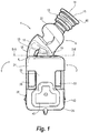
- Fig. 1 is a schematic first side view of an exemplary suspension 1.
- the suspension comprises a receiver holding part 2 and a damping structure 4.
- the damping structure 4 has a body 6 and a receiver base 8 .
- the body 6 comprises a first body part 10 extending from the receiver base 8.
- the damping structure 4 has an inner surface forming a sound duct 11 (see Fig. 6 ) in the damping structure 4 extending through the first body part 10.
- the damping structure 4 has a first opening 12 (see Fig. 6 and 8 ) at a first sound duct end 13, wherein the first opening 12 is configured for connecting an output port of a receiver to the sound duct 11.
- the receiver is positioned inside the receiver holding part 2.
- the damping structure 4 has a second opening 14 (see Fig.
- the sound duct provides a sound path for conveying sound energy from the receiver, positioned inside or otherwise mounted to the receiver holding part 2, through the damping structure to the second opening 14.
- the sound duct 11 of the suspension 1 has a constant circular cross section from the first opening 12 to the second opening 14.
- the sound duct radius depends on the receiver type and is in illustrated suspension 1 in the range from 0.75 mm to 1.5 mm.
- the damping structure 4 comprises a first damping element 16 connecting the body 6 and the receiver base 8 separate from and in parallel to the first body part 10.
- the body 6 comprises a second body part 18 positioned between the second sound duct end 15 and the first body part 10.
- the sound duct 11 extends through the second body part 18 and the second body part 18 has a corrugated second outer surface.
- the first damping element 16 extends from the receiver base 8 to the body 6 in parallel to the first body part 10 forming a gap 19 between the first damping element 16 and the first body part 10, the gap 19 having a maximum gap or gap opening larger than 1 mm. Separating the first damping element 16 from the first body part 10 provides improved damping of one or more selected frequencies or frequency ranges.
- the first body part 10 comprises a second damping element 20 extending from the receiver base 8.
- the second damping element 20 is integrated in the first body part 10 and a first outer surface of the first body part in a cross section perpendicular to the sound duct is non-circular.
- the body 6 comprises a third body part 22 between the first body part 10 and the second body part 18.
- the third body part 22 is absorbing a part of the vibrational energy from the receiver positioned inside the receiver holding part 2.
- the receiver holding part 2 forms a receiver compartment and comprises a first portion 24 connected to the receiver base part 8, and a second portion 26.
- the first portion 24 and the second portion 26 are connected by a plurality of bridge elements 28, 30, 32, 34.
- the second portion 26 of the receiver holding part 2 comprises one or a plurality of cushion structures 38, 40, 42, 44, e.g. configured for absorbing mechanical shock.
- the damping structure 4 comprises a mounting element 46 at the second sound duct end 15.
- the mounting element 46 is configured for mounting the suspension 1 to a structural frame of a hearing device and in the illustrated suspension 1 takes the form of a flange.
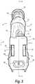
- Figs. 2 and 3 are schematic second and third side views of the suspension 1 in Fig. 1 ,
- the second body part 18 has one or more annular bulges 48 forming a corrugated second outer surface of the second body part 18 along the sound duct 11.
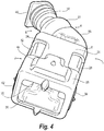
- Fig. 4 is a schematic perspective view of the suspension 1 in Fig. 1 .
- the second portion 26 forms an insertion opening 36 for insertion of a hearing aid receiver in the receiver compartment formed by the receiver holding part 2.
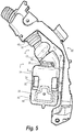
- Fig. 5 schematically illustrates a side view of an exemplary hearing device structural frame 50 with a suspension 1 mounted thereon.
- a behind-the-ear hearing device may then accommodate a hearing device structural frame 50 and a suspension 1, wherein the hearing device receiver is to be mounted in the suspension 1.
- Fig. 6 schematically illustrates an exemplary cut view through the suspension along the line A-A in Fig. 3 .
- a first longitudinal axis X 1 of a first sound duct part in the first body part 10, and a second longitudinal axis X 2 of a second sound duct part in the second body part 18 forms an angle ⁇ of 42°.
- a first longitudinal axis X 1 of a first sound duct part in the first body part, and a second longitudinal axis X 2 of a second sound duct part in the second body part may form an angle ⁇ in the range from 15° to 55°, such as from 35° to 50°, advantageously from 40° to 45°.
- the sound duct 11 has a substantially constant cross-sectional circular shape and constant cross sectional area from the first sound duct end 13 to the second sound duct end 15.
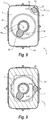
- Fig. 7 schematically illustrates an end view of the receiver suspension 1 in Fig. 1 .
- a receiver (not shown) may be mounted in the receiver compartment formed by the receiver holding part 2 through the insertion opening 36 such that an output port of the receiver is fitted into the first opening 12 for feeding sound from the receiver into the sound duct 11.
- Fig. 8 schematically illustrates a first cross section perpendicular to the sound duct along the line B-B in Fig. 1 .
- the first damping element 16 covers an area A 1,damp1 in the first cross-section of less than 10% of a receiver base area A base being the maximum area spanned by the receiver base 8 perpendicular to the first longitudinal axis X 1 .
- the receiver base area A base may be in the range from 20 mm 2 to 200 mm 2 .
- the first body part 10 and the second damping element 20 are integrated, and the first outer surface of the first body part 10 has a non-circular shape in the first cross section.
- the first damping element 16 extends from a corner section 52 of the receiver base 8 within a corner distance of 3 mm from a receiver base corner 53.
- the first outer surface of the first body part 10 comprises a first concave section 54 and optionally a second concave section 56.
- Fig. 9 schematically illustrates a first cross section perpendicular to the sound duct of an exemplary suspension 1'.
- the first damping element 16 extends from an edge section 60 of the receiver base within an edge distance of 3 mm from the receiver base edge 62.
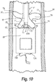
- Fig. 10 illustrates an exemplary suspension 1" according to the invention.
- the suspension is shown mounted within a hearing device housing 64.
- the hearing device housing 64 is depicted as a section in order to more clearly illustrate the positioning of the receiver suspension 1".
- a receiver 65 is mounted in the suspension 1".
- the suspension 1" comprises a receiver holding part 2 and a damping structure 4.
- the damping structure 4 has a body 6 and a receiver base 8.
- the body 6 comprises a first body part 10 extending from the receiver base 8.
- the damping structure 4 has an inner surface forming a sound duct in the damping structure 4 extending through the first body part 10.
- the damping structure 4 has a first opening at a first sound duct end 13 in the receiver base 8/receiver holding part 2.
- the receiver base 8 with the first opening is configured for mounting the receiver 65 to the suspension 1" and for connecting an output port 65A of the receiver to the sound duct 11.
- the receiver output of the receiver may as illustrated comprise a tube portion with an end forming the output port 65A.
- the tube portion facilitates mounting to the suspension by extending slightly into the sound duct 11.
- the sound duct 11 provides a sound path for conveying sound energy from the receiver 65 mounted to the receiver holding part 2, through the damping structure to the second opening (not shown).
- the damping structure 4 comprises a first damping element 16 and optionally a second damping element 20 extending from a second body part 18 separate from and in parallel to the first body part 10.
- the first damping element 16 and the second damping element 20 each extend as a protrusion from the body (second body part 18) of the damping structure, each protrusion having a distal end.
- the first damping element 16 and the second damping element 20 comprise respective first support surface 66 and second support surface 68 each configured for contacting or supporting on a point or outer surface of receiver housing 69 when the receiver 65 is mounted in the suspension.
- the first support surface 66 may be arranged near or at the distal end of the first damping element 16.
- the second support surface 68 may be arranged near or at the distal end of the second damping element 20.
- the damping structure 4 optionally comprises one or more damping elements configured for contacting a point or surface of a hearing device structural frame or hearing device housing when the suspension is mounted in the hearing device.
- the damping structure comprises a third damping element 70 protruding from the body and comprising a third support surface 72 for contacting a point or surface of a hearing device structural frame or hearing device housing when the suspension is mounted in the hearing device.
- the third support surface 72 may be arranged near or at the distal end of the third damping element 70.
- the damping structure comprises a fourth damping element 74 protruding from the body (e.g.
- the receiver may have a first electrical terminal 73A and a second electrical terminal 73B configured for electrical connection to the hearing aid circuitry (not shown).
Claims (12)
- Suspension (1) pour un récepteur (65) dans une prothèse auditive, la suspension (1) comprenant :- une partie de maintien du récepteur (2) formant un compartiment de réception, et- une structure d'amortissement (4) avec un corps (6) et une base de réception (8), le corps (6) comprenant une première partie de corps (10), la structure d'amortissement (4) ayant une surface intérieure formant un conduit de son (11) dans la structure d'amortissement (4), le conduit de son (11) s'étendant à travers la première partie de corps (10), la structure d'amortissement (4) ayant une première ouverture (12) au niveau d'une première extrémité du conduit de son (13), la première ouverture (12) étant configurée pour connecter un port de sortie (65A) du récepteur (65) au conduit de son (11), la structure d'amortissement (4) présentant une deuxième ouverture (14) au niveau d'une deuxième extrémité du conduit de son (15), le conduit de son (11) fournissant un trajet de son pour le transport d'énergie sonore du récepteur (65) à travers la structure d'amortissement (4) jusqu'à la deuxième ouverture (14), la première partie de corps (10) s'étendant depuis la base de réception (8), la structure d'amortissement (4) comprenant au moins un premier élément d'amortissement (16) s'étendant de manière séparée de la première partie de corps (10) et en parallèle à celle-ci,caractérisée en ce que le premier élément d'amortissement (16) s'étend depuis la base de réception (8) vers le corpos (6) formant un intervalle (19) entre le premier élément d'amortissement (16) et la première partie de corps (10) ; dans laquelle le premier élément d'amortissement (16), dans une première section transversale perpendiculaire au premier axe longitudinal (X1) d'une première partie du conduit de son dans la première partie de corps (10), couvre une surface inférieure à 10% de la surface de base de réception (8) ;
dans laquelle une première surface extérieure de la première partie de corps (10) dans une section transversale perpendiculaire au conduit de son (11) est non circulaire ; et
dans laquelle la structure d'amortissement(4) comprend un élément de montage (46) au niveau de la deuxième ouverture (14) pour monter la suspension (1) sur un cadre structurel (50) de la prothèse auditive. - Suspension selon la revendication 1, dans laquelle le premier élément d'amortissement relie le corps et la base de réception de manière séparée de la première partie de corps et en parallèle à celle-ci.
- Suspension selon l'une quelconque des revendications 1 à 2, dans laquelle le corps comprend une deuxième partie de corps positionnée entre la deuxième extrémité du conduit de son et la première partie de corps, le conduit de son s'étendant à travers la deuxième partie de corps, et la deuxième partie de corps ayant une deuxième surface extérieure ondulée.
- Suspension selon l'une quelconque des revendications précédentes, dans laquelle la première partie de corps comprend un deuxième élément d'amortissement s'étendant depuis la base de réception.
- Suspension selon l'une quelconque des revendications 1 à 3, dans laquelle la structure d'amortissement comprend un deuxième élément d'amortissement s'étendant de manière séparée de la première partie de corps et en parallèle à celle-ci.
- Suspension selon l'une quelconque des revendications précédentes étant dépendent de la revendication 3,
dans laquelle un premier axe longitudinal d'une première partie du conduit de son dans la première partie de corps et un deuxième axe longitudinal d'une deuxième partie du conduit de son dans la deuxième partie de corps forment un angle dans la plage de 15° à 45°. - Suspension selon l'une quelconque des revendications précédentes étant dépendent de la revendication 3,
dans laquelle le corps comprend une troisième partie de corps entre la première partie de corps et la deuxième partie de corps pour absorber une partie de l'énergie vibratoire provenant du récepteur. - Suspension selon l'une quelconque des revendications précédentes, dans laquelle la partie de maintien de récepteur comprend une première partie connectée à la partie de base de réception, et une deuxième partie, la première partie et la deuxième partie étant connectées par une pluralité d'éléments de pontage adaptés pour enfermer le récepteur, et dans laquelle la deuxième partie de la partie de maintien de récepteur comprend une pluralité de zones de rembourrage pour absorber des chocs mécaniques.
- Suspension selon la revendication 8, dans laquelle la deuxième partie comprend une ouverture d'insertion pour l'insertion d'un récepteur de prothèse auditive dans le compartiment de réception.
- Suspension selon l'une quelconque des revendications précédentes, dans laquelle la structure d'amortissement comprend au moins un troisième élément d'amortissement faisant saillie du corps et comprenant une surface de support configurée pour entrer en contact avec un seul point sur la surface intérieure d'un boîtier d'une prothèse auditive lorsque la suspension est montée dans la prothèse auditive.
- Prothèse auditive comprenant un récepteur de prothèse auditive, un cadre structural de prothèse auditive et une suspension selon l'une des revendications précédentes, dans laquelle le récepteur de prothèse auditive est montée dans la suspension.
- Prothèse auditive selon la revendication 11, dans laquelle le port de sortie du récepteur est positionné dans la première ouverture du conduit de son.
Priority Applications (3)
| Application Number | Priority Date | Filing Date | Title |
|---|---|---|---|
| EP19199866.5A EP3627858B1 (fr) | 2013-10-17 | 2014-10-15 | Suspension pour récepteur de dispositif auditif |
| DK19199866.5T DK3627858T3 (en) | 2013-10-17 | 2014-10-15 | Telefonophæng til et høreapparat |
| EP14784089.6A EP3058761B1 (fr) | 2013-10-17 | 2014-10-15 | Suspension pour récepteur de dispositif auditif |
Applications Claiming Priority (5)
| Application Number | Priority Date | Filing Date | Title |
|---|---|---|---|
| DKPA201370593 | 2013-10-17 | ||
| US14/056,807 US9247329B2 (en) | 2013-10-17 | 2013-10-17 | Suspension for a hearing device receiver |
| EP13189046 | 2013-10-17 | ||
| PCT/EP2014/072151 WO2015055735A2 (fr) | 2013-10-17 | 2014-10-15 | Suspension pour récepteur de dispositif auditif |
| EP14784089.6A EP3058761B1 (fr) | 2013-10-17 | 2014-10-15 | Suspension pour récepteur de dispositif auditif |
Related Child Applications (2)
| Application Number | Title | Priority Date | Filing Date |
|---|---|---|---|
| EP19199866.5A Division EP3627858B1 (fr) | 2013-10-17 | 2014-10-15 | Suspension pour récepteur de dispositif auditif |
| EP19199866.5A Division-Into EP3627858B1 (fr) | 2013-10-17 | 2014-10-15 | Suspension pour récepteur de dispositif auditif |
Publications (2)
| Publication Number | Publication Date |
|---|---|
| EP3058761A2 EP3058761A2 (fr) | 2016-08-24 |
| EP3058761B1 true EP3058761B1 (fr) | 2019-12-04 |
Family
ID=52826207
Family Applications (2)
| Application Number | Title | Priority Date | Filing Date |
|---|---|---|---|
| EP14784089.6A Active EP3058761B1 (fr) | 2013-10-17 | 2014-10-15 | Suspension pour récepteur de dispositif auditif |
| EP19199866.5A Active EP3627858B1 (fr) | 2013-10-17 | 2014-10-15 | Suspension pour récepteur de dispositif auditif |
Family Applications After (1)
| Application Number | Title | Priority Date | Filing Date |
|---|---|---|---|
| EP19199866.5A Active EP3627858B1 (fr) | 2013-10-17 | 2014-10-15 | Suspension pour récepteur de dispositif auditif |
Country Status (6)
| Country | Link |
|---|---|
| US (1) | US9247329B2 (fr) |
| EP (2) | EP3058761B1 (fr) |
| JP (1) | JP6546915B2 (fr) |
| CN (1) | CN105794227B (fr) |
| DK (2) | DK3627858T3 (fr) |
| WO (1) | WO2015055735A2 (fr) |
Families Citing this family (6)
| Publication number | Priority date | Publication date | Assignee | Title |
|---|---|---|---|---|
| US10021493B2 (en) | 2015-09-25 | 2018-07-10 | Starkey Laboratories, Inc. | Suspension assembly for hearing aid receiver |
| EP3624466B1 (fr) * | 2015-09-30 | 2024-04-03 | Oticon A/s | Prothèse auditive comprenant un ensemble récepteur |
| US10057697B2 (en) * | 2015-10-26 | 2018-08-21 | Oticon A/S | Hearing device with a barrier element |
| US10616680B2 (en) * | 2016-12-16 | 2020-04-07 | Sonion Nederland B.V. | Receiver assembly |
| DK3337192T3 (en) | 2016-12-16 | 2021-05-10 | Sonion Nederland Bv | A receiver assembly |
| DE102021206011A1 (de) * | 2021-06-14 | 2022-12-15 | Sivantos Pte. Ltd. | Hörvorrichtung |
Family Cites Families (18)
| Publication number | Priority date | Publication date | Assignee | Title |
|---|---|---|---|---|
| US5902023A (en) | 1998-01-07 | 1999-05-11 | Proton Electronic Industrial Co., Ltd. | Speaker cabinet and monitor housing mounting arrangement |
| DE19948375B4 (de) | 1999-10-07 | 2004-04-01 | Phonak Ag | Anordnung zum mechanischen Ankoppeln eines Treibers an eine Ankoppelstelle der Ossikelkette |
| EP1248496A3 (fr) | 2001-04-04 | 2005-11-02 | Sonionmicrotronic Nederland B.V. | Récepteur acoustique avec suspension mécanique améliorée |
| DE10214187C1 (de) | 2002-03-28 | 2003-10-16 | Siemens Audiologische Technik | Lagerung eines elektroakustischen Miniaturwandlers in einem Gerät, insbesondere einem Hörhilfegerät, sowie elektroakustischer Miniaturwandler |
| WO2004008803A1 (fr) | 2002-07-12 | 2004-01-22 | Oticon A/S | Moyens de suspension pour transducteur |
| WO2004100608A2 (fr) | 2003-04-03 | 2004-11-18 | Sonic Innovations, Inc. | Systeme de pose d'un appareil auditif extensible par ballonnet et appareil auditif a deploiement automatique |
| US6938889B2 (en) | 2003-10-15 | 2005-09-06 | Pao-An Chuang | Shock absorbing and magnetic levitating cushion |
| US20080317269A1 (en) | 2003-12-05 | 2008-12-25 | Claus Tipsmark | Communication Device with Structural Part |
| JP2005252420A (ja) * | 2004-03-02 | 2005-09-15 | Rion Co Ltd | 耳あな形補聴器 |
| JP4709274B2 (ja) * | 2005-03-10 | 2011-06-22 | ヴェーデクス・アクティーセルスカプ | 補聴器用イヤープラグ |
| US20070036378A1 (en) | 2005-07-15 | 2007-02-15 | Knowles Electronics, Llc | Shock resistant and vibration isolated electroacoustical transducer assembly |
| DE102006029819A1 (de) * | 2006-06-28 | 2008-01-03 | Siemens Audiologische Technik Gmbh | Hörgerät mit einer Befestigung für einen Hörerschlauch |
| DE102007028225A1 (de) * | 2007-06-20 | 2009-01-02 | Siemens Medical Instruments Pte. Ltd. | Schallausgangsröhrchen mit 2-Komponenten-Aufbau |
| DE102007061310A1 (de) | 2007-12-19 | 2009-06-25 | Siemens Medical Instruments Pte. Ltd. | Elektroakustischer Miniaturwandler mit Haltemittel zum Einbau in ein Hörgerät |
| DE102008052683B3 (de) | 2008-10-22 | 2010-04-01 | Siemens Medical Instruments Pte. Ltd. | Hörereinrichtung und Hörgerät |
| DE102009032981B4 (de) * | 2009-07-14 | 2013-11-28 | Siemens Medical Instruments Pte. Ltd. | Hörerschlauch |
| JP5715707B2 (ja) | 2010-11-11 | 2015-05-13 | ジーエヌ リザウンド エー/エスGn Resound A/S | 聴覚装置のレシーバ用のサスペンション、聴覚装置の製造方法、および聴覚装置 |
| US8737657B2 (en) * | 2010-11-11 | 2014-05-27 | Gn Resound A/S | Suspension for a hearing device receiver, and a method of producing a hearing device, and a hearing device |
-
2013
- 2013-10-17 US US14/056,807 patent/US9247329B2/en active Active
-
2014
- 2014-10-15 CN CN201480065553.3A patent/CN105794227B/zh active Active
- 2014-10-15 EP EP14784089.6A patent/EP3058761B1/fr active Active
- 2014-10-15 WO PCT/EP2014/072151 patent/WO2015055735A2/fr active Application Filing
- 2014-10-15 EP EP19199866.5A patent/EP3627858B1/fr active Active
- 2014-10-15 DK DK19199866.5T patent/DK3627858T3/da active
- 2014-10-15 DK DK14784089.6T patent/DK3058761T3/da active
- 2014-10-15 JP JP2016523251A patent/JP6546915B2/ja not_active Expired - Fee Related
Non-Patent Citations (1)
| Title |
|---|
| None * |
Also Published As
| Publication number | Publication date |
|---|---|
| DK3627858T3 (en) | 2023-05-22 |
| CN105794227B (zh) | 2019-12-03 |
| US9247329B2 (en) | 2016-01-26 |
| EP3058761A2 (fr) | 2016-08-24 |
| JP6546915B2 (ja) | 2019-07-17 |
| DK3058761T3 (da) | 2020-02-10 |
| WO2015055735A2 (fr) | 2015-04-23 |
| CN105794227A (zh) | 2016-07-20 |
| WO2015055735A3 (fr) | 2015-06-11 |
| EP3627858B1 (fr) | 2023-03-08 |
| US20150110328A1 (en) | 2015-04-23 |
| EP3627858A1 (fr) | 2020-03-25 |
| JP2016533665A (ja) | 2016-10-27 |
Similar Documents
| Publication | Publication Date | Title |
|---|---|---|
| EP3058761B1 (fr) | Suspension pour récepteur de dispositif auditif | |
| US4440982A (en) | Hearing aid | |
| US7477756B2 (en) | Isolating deep canal fitting earphone | |
| CN102318368B (zh) | 耳机 | |
| US7076074B2 (en) | Bearing of an electroacoustic miniature transducer in a device, particularly a hearing aid device, as well as an electroacoustic miniature transducer | |
| US8103031B2 (en) | Hearing device sound emission tube with a 2-component design | |
| US7324653B2 (en) | Suspension means for transducer | |
| JP2017103618A (ja) | インナーイヤホン | |
| JP5715707B2 (ja) | 聴覚装置のレシーバ用のサスペンション、聴覚装置の製造方法、および聴覚装置 | |
| WO2011046508A1 (fr) | Suspensions elastomeres et structures de cadres integrees pour composants electroniques | |
| US10873818B2 (en) | Damping device for a receiver of a hearing instrument and hearing instrument having such a damping device | |
| US8737657B2 (en) | Suspension for a hearing device receiver, and a method of producing a hearing device, and a hearing device | |
| KR101634755B1 (ko) | 난청 방지 이어폰 | |
| US11019435B2 (en) | Hearing instrument having a coupling unit for the vibration-damped mounting of a receiver | |
| US10863292B2 (en) | Elastic damping element for hearing instrument receiver and hearing instrument with such a damping element | |
| WO2006137665A1 (fr) | Unite de micro haut-parleur | |
| JP3246493U (ja) | スピーカー | |
| KR102377495B1 (ko) | 보청기용 리시버 고정 포켓 | |
| KR102430360B1 (ko) | 멀티 이어팁 | |
| CN113115189B (zh) | 扬声器盒和听力设备 | |
| WO2023166899A1 (fr) | Transducteur électroacoustique et casque d'écoute | |
| US20220400333A1 (en) | Hearing device | |
| CN108293160B (zh) | 电动式声变换器 | |
| EP2453674B1 (fr) | Suspension pour récepteur de dispositif auditif, et procédé de production d'un dispositif auditif et dispositif auditif |
Legal Events
| Date | Code | Title | Description |
|---|---|---|---|
| PUAI | Public reference made under article 153(3) epc to a published international application that has entered the european phase |
Free format text: ORIGINAL CODE: 0009012 |
|
| 17P | Request for examination filed |
Effective date: 20160426 |
|
| AK | Designated contracting states |
Kind code of ref document: A2 Designated state(s): AL AT BE BG CH CY CZ DE DK EE ES FI FR GB GR HR HU IE IS IT LI LT LU LV MC MK MT NL NO PL PT RO RS SE SI SK SM TR |
|
| AX | Request for extension of the european patent |
Extension state: BA ME |
|
| DAX | Request for extension of the european patent (deleted) | ||
| STAA | Information on the status of an ep patent application or granted ep patent |
Free format text: STATUS: EXAMINATION IS IN PROGRESS |
|
| 17Q | First examination report despatched |
Effective date: 20170804 |
|
| RIC1 | Information provided on ipc code assigned before grant |
Ipc: H04R 1/10 20060101ALN20190412BHEP Ipc: H04R 25/00 20060101AFI20190412BHEP |
|
| GRAP | Despatch of communication of intention to grant a patent |
Free format text: ORIGINAL CODE: EPIDOSNIGR1 |
|
| STAA | Information on the status of an ep patent application or granted ep patent |
Free format text: STATUS: GRANT OF PATENT IS INTENDED |
|
| RIC1 | Information provided on ipc code assigned before grant |
Ipc: H04R 1/10 20060101ALN20190515BHEP Ipc: H04R 25/00 20060101AFI20190515BHEP |
|
| INTG | Intention to grant announced |
Effective date: 20190604 |
|
| RIN1 | Information on inventor provided before grant (corrected) |
Inventor name: SOENDERGAARD, MORTEN BIRKMOSE |
|
| GRAS | Grant fee paid |
Free format text: ORIGINAL CODE: EPIDOSNIGR3 |
|
| RAP1 | Party data changed (applicant data changed or rights of an application transferred) |
Owner name: GN HEARING A/S |
|
| GRAA | (expected) grant |
Free format text: ORIGINAL CODE: 0009210 |
|
| STAA | Information on the status of an ep patent application or granted ep patent |
Free format text: STATUS: THE PATENT HAS BEEN GRANTED |
|
| AK | Designated contracting states |
Kind code of ref document: B1 Designated state(s): AL AT BE BG CH CY CZ DE DK EE ES FI FR GB GR HR HU IE IS IT LI LT LU LV MC MK MT NL NO PL PT RO RS SE SI SK SM TR |
|
| REG | Reference to a national code |
Ref country code: GB Ref legal event code: FG4D |
|
| REG | Reference to a national code |
Ref country code: CH Ref legal event code: EP |
|
| REG | Reference to a national code |
Ref country code: AT Ref legal event code: REF Ref document number: 1211026 Country of ref document: AT Kind code of ref document: T Effective date: 20191215 |
|
| REG | Reference to a national code |
Ref country code: DE Ref legal event code: R096 Ref document number: 602014057870 Country of ref document: DE |
|
| REG | Reference to a national code |
Ref country code: IE Ref legal event code: FG4D |
|
| REG | Reference to a national code |
Ref country code: DK Ref legal event code: T3 Effective date: 20200207 |
|
| REG | Reference to a national code |
Ref country code: NL Ref legal event code: MP Effective date: 20191204 |
|
| REG | Reference to a national code |
Ref country code: LT Ref legal event code: MG4D |
|
| PG25 | Lapsed in a contracting state [announced via postgrant information from national office to epo] |
Ref country code: NO Free format text: LAPSE BECAUSE OF FAILURE TO SUBMIT A TRANSLATION OF THE DESCRIPTION OR TO PAY THE FEE WITHIN THE PRESCRIBED TIME-LIMIT Effective date: 20200304 Ref country code: GR Free format text: LAPSE BECAUSE OF FAILURE TO SUBMIT A TRANSLATION OF THE DESCRIPTION OR TO PAY THE FEE WITHIN THE PRESCRIBED TIME-LIMIT Effective date: 20200305 Ref country code: BG Free format text: LAPSE BECAUSE OF FAILURE TO SUBMIT A TRANSLATION OF THE DESCRIPTION OR TO PAY THE FEE WITHIN THE PRESCRIBED TIME-LIMIT Effective date: 20200304 Ref country code: LT Free format text: LAPSE BECAUSE OF FAILURE TO SUBMIT A TRANSLATION OF THE DESCRIPTION OR TO PAY THE FEE WITHIN THE PRESCRIBED TIME-LIMIT Effective date: 20191204 Ref country code: SE Free format text: LAPSE BECAUSE OF FAILURE TO SUBMIT A TRANSLATION OF THE DESCRIPTION OR TO PAY THE FEE WITHIN THE PRESCRIBED TIME-LIMIT Effective date: 20191204 Ref country code: LV Free format text: LAPSE BECAUSE OF FAILURE TO SUBMIT A TRANSLATION OF THE DESCRIPTION OR TO PAY THE FEE WITHIN THE PRESCRIBED TIME-LIMIT Effective date: 20191204 Ref country code: FI Free format text: LAPSE BECAUSE OF FAILURE TO SUBMIT A TRANSLATION OF THE DESCRIPTION OR TO PAY THE FEE WITHIN THE PRESCRIBED TIME-LIMIT Effective date: 20191204 |
|
| PG25 | Lapsed in a contracting state [announced via postgrant information from national office to epo] |
Ref country code: HR Free format text: LAPSE BECAUSE OF FAILURE TO SUBMIT A TRANSLATION OF THE DESCRIPTION OR TO PAY THE FEE WITHIN THE PRESCRIBED TIME-LIMIT Effective date: 20191204 Ref country code: RS Free format text: LAPSE BECAUSE OF FAILURE TO SUBMIT A TRANSLATION OF THE DESCRIPTION OR TO PAY THE FEE WITHIN THE PRESCRIBED TIME-LIMIT Effective date: 20191204 |
|
| PG25 | Lapsed in a contracting state [announced via postgrant information from national office to epo] |
Ref country code: AL Free format text: LAPSE BECAUSE OF FAILURE TO SUBMIT A TRANSLATION OF THE DESCRIPTION OR TO PAY THE FEE WITHIN THE PRESCRIBED TIME-LIMIT Effective date: 20191204 |
|
| PG25 | Lapsed in a contracting state [announced via postgrant information from national office to epo] |
Ref country code: PT Free format text: LAPSE BECAUSE OF FAILURE TO SUBMIT A TRANSLATION OF THE DESCRIPTION OR TO PAY THE FEE WITHIN THE PRESCRIBED TIME-LIMIT Effective date: 20200429 Ref country code: ES Free format text: LAPSE BECAUSE OF FAILURE TO SUBMIT A TRANSLATION OF THE DESCRIPTION OR TO PAY THE FEE WITHIN THE PRESCRIBED TIME-LIMIT Effective date: 20191204 Ref country code: CZ Free format text: LAPSE BECAUSE OF FAILURE TO SUBMIT A TRANSLATION OF THE DESCRIPTION OR TO PAY THE FEE WITHIN THE PRESCRIBED TIME-LIMIT Effective date: 20191204 Ref country code: NL Free format text: LAPSE BECAUSE OF FAILURE TO SUBMIT A TRANSLATION OF THE DESCRIPTION OR TO PAY THE FEE WITHIN THE PRESCRIBED TIME-LIMIT Effective date: 20191204 Ref country code: RO Free format text: LAPSE BECAUSE OF FAILURE TO SUBMIT A TRANSLATION OF THE DESCRIPTION OR TO PAY THE FEE WITHIN THE PRESCRIBED TIME-LIMIT Effective date: 20191204 Ref country code: EE Free format text: LAPSE BECAUSE OF FAILURE TO SUBMIT A TRANSLATION OF THE DESCRIPTION OR TO PAY THE FEE WITHIN THE PRESCRIBED TIME-LIMIT Effective date: 20191204 |
|
| PG25 | Lapsed in a contracting state [announced via postgrant information from national office to epo] |
Ref country code: SM Free format text: LAPSE BECAUSE OF FAILURE TO SUBMIT A TRANSLATION OF THE DESCRIPTION OR TO PAY THE FEE WITHIN THE PRESCRIBED TIME-LIMIT Effective date: 20191204 Ref country code: SK Free format text: LAPSE BECAUSE OF FAILURE TO SUBMIT A TRANSLATION OF THE DESCRIPTION OR TO PAY THE FEE WITHIN THE PRESCRIBED TIME-LIMIT Effective date: 20191204 Ref country code: IS Free format text: LAPSE BECAUSE OF FAILURE TO SUBMIT A TRANSLATION OF THE DESCRIPTION OR TO PAY THE FEE WITHIN THE PRESCRIBED TIME-LIMIT Effective date: 20200404 |
|
| REG | Reference to a national code |
Ref country code: DE Ref legal event code: R097 Ref document number: 602014057870 Country of ref document: DE |
|
| REG | Reference to a national code |
Ref country code: AT Ref legal event code: MK05 Ref document number: 1211026 Country of ref document: AT Kind code of ref document: T Effective date: 20191204 |
|
| PLBE | No opposition filed within time limit |
Free format text: ORIGINAL CODE: 0009261 |
|
| STAA | Information on the status of an ep patent application or granted ep patent |
Free format text: STATUS: NO OPPOSITION FILED WITHIN TIME LIMIT |
|
| 26N | No opposition filed |
Effective date: 20200907 |
|
| PG25 | Lapsed in a contracting state [announced via postgrant information from national office to epo] |
Ref country code: AT Free format text: LAPSE BECAUSE OF FAILURE TO SUBMIT A TRANSLATION OF THE DESCRIPTION OR TO PAY THE FEE WITHIN THE PRESCRIBED TIME-LIMIT Effective date: 20191204 Ref country code: SI Free format text: LAPSE BECAUSE OF FAILURE TO SUBMIT A TRANSLATION OF THE DESCRIPTION OR TO PAY THE FEE WITHIN THE PRESCRIBED TIME-LIMIT Effective date: 20191204 Ref country code: PL Free format text: LAPSE BECAUSE OF FAILURE TO SUBMIT A TRANSLATION OF THE DESCRIPTION OR TO PAY THE FEE WITHIN THE PRESCRIBED TIME-LIMIT Effective date: 20191204 |
|
| PG25 | Lapsed in a contracting state [announced via postgrant information from national office to epo] |
Ref country code: IT Free format text: LAPSE BECAUSE OF FAILURE TO SUBMIT A TRANSLATION OF THE DESCRIPTION OR TO PAY THE FEE WITHIN THE PRESCRIBED TIME-LIMIT Effective date: 20191204 |
|
| PG25 | Lapsed in a contracting state [announced via postgrant information from national office to epo] |
Ref country code: MC Free format text: LAPSE BECAUSE OF FAILURE TO SUBMIT A TRANSLATION OF THE DESCRIPTION OR TO PAY THE FEE WITHIN THE PRESCRIBED TIME-LIMIT Effective date: 20191204 Ref country code: LU Free format text: LAPSE BECAUSE OF NON-PAYMENT OF DUE FEES Effective date: 20201015 |
|
| REG | Reference to a national code |
Ref country code: BE Ref legal event code: MM Effective date: 20201031 |
|
| PG25 | Lapsed in a contracting state [announced via postgrant information from national office to epo] |
Ref country code: BE Free format text: LAPSE BECAUSE OF NON-PAYMENT OF DUE FEES Effective date: 20201031 |
|
| PG25 | Lapsed in a contracting state [announced via postgrant information from national office to epo] |
Ref country code: IE Free format text: LAPSE BECAUSE OF NON-PAYMENT OF DUE FEES Effective date: 20201015 |
|
| PGFP | Annual fee paid to national office [announced via postgrant information from national office to epo] |
Ref country code: DK Payment date: 20211025 Year of fee payment: 8 Ref country code: GB Payment date: 20211022 Year of fee payment: 8 |
|
| PGFP | Annual fee paid to national office [announced via postgrant information from national office to epo] |
Ref country code: FR Payment date: 20211015 Year of fee payment: 8 Ref country code: CH Payment date: 20211021 Year of fee payment: 8 |
|
| PG25 | Lapsed in a contracting state [announced via postgrant information from national office to epo] |
Ref country code: TR Free format text: LAPSE BECAUSE OF FAILURE TO SUBMIT A TRANSLATION OF THE DESCRIPTION OR TO PAY THE FEE WITHIN THE PRESCRIBED TIME-LIMIT Effective date: 20191204 Ref country code: MT Free format text: LAPSE BECAUSE OF FAILURE TO SUBMIT A TRANSLATION OF THE DESCRIPTION OR TO PAY THE FEE WITHIN THE PRESCRIBED TIME-LIMIT Effective date: 20191204 Ref country code: CY Free format text: LAPSE BECAUSE OF FAILURE TO SUBMIT A TRANSLATION OF THE DESCRIPTION OR TO PAY THE FEE WITHIN THE PRESCRIBED TIME-LIMIT Effective date: 20191204 |
|
| PG25 | Lapsed in a contracting state [announced via postgrant information from national office to epo] |
Ref country code: MK Free format text: LAPSE BECAUSE OF FAILURE TO SUBMIT A TRANSLATION OF THE DESCRIPTION OR TO PAY THE FEE WITHIN THE PRESCRIBED TIME-LIMIT Effective date: 20191204 |
|
| REG | Reference to a national code |
Ref country code: DK Ref legal event code: EBP Effective date: 20221031 |
|
| REG | Reference to a national code |
Ref country code: CH Ref legal event code: PL |
|
| GBPC | Gb: european patent ceased through non-payment of renewal fee |
Effective date: 20221015 |
|
| PG25 | Lapsed in a contracting state [announced via postgrant information from national office to epo] |
Ref country code: LI Free format text: LAPSE BECAUSE OF NON-PAYMENT OF DUE FEES Effective date: 20221031 Ref country code: FR Free format text: LAPSE BECAUSE OF NON-PAYMENT OF DUE FEES Effective date: 20221031 Ref country code: CH Free format text: LAPSE BECAUSE OF NON-PAYMENT OF DUE FEES Effective date: 20221031 |
|
| PG25 | Lapsed in a contracting state [announced via postgrant information from national office to epo] |
Ref country code: GB Free format text: LAPSE BECAUSE OF NON-PAYMENT OF DUE FEES Effective date: 20221015 Ref country code: DK Free format text: LAPSE BECAUSE OF NON-PAYMENT OF DUE FEES Effective date: 20221031 |
|
| PGFP | Annual fee paid to national office [announced via postgrant information from national office to epo] |
Ref country code: DE Payment date: 20231020 Year of fee payment: 10 |