EP3058285B1 - Klimatisiertes gebäude und entsprechendes verfahren zur klimatisierung des gebäudes - Google Patents
Klimatisiertes gebäude und entsprechendes verfahren zur klimatisierung des gebäudes Download PDFInfo
- Publication number
- EP3058285B1 EP3058285B1 EP14793894.8A EP14793894A EP3058285B1 EP 3058285 B1 EP3058285 B1 EP 3058285B1 EP 14793894 A EP14793894 A EP 14793894A EP 3058285 B1 EP3058285 B1 EP 3058285B1
- Authority
- EP
- European Patent Office
- Prior art keywords
- walls
- heat
- hollow space
- carrying fluid
- compartment
- Prior art date
- Legal status (The legal status is an assumption and is not a legal conclusion. Google has not performed a legal analysis and makes no representation as to the accuracy of the status listed.)
- Active
Links
Images


Classifications
-
- F—MECHANICAL ENGINEERING; LIGHTING; HEATING; WEAPONS; BLASTING
- F24—HEATING; RANGES; VENTILATING
- F24F—AIR-CONDITIONING; AIR-HUMIDIFICATION; VENTILATION; USE OF AIR CURRENTS FOR SCREENING
- F24F3/00—Air-conditioning systems in which conditioned primary air is supplied from one or more central stations to distributing units in the rooms or spaces where it may receive secondary treatment; Apparatus specially designed for such systems
- F24F3/044—Systems in which all treatment is given in the central station, i.e. all-air systems
-
- F—MECHANICAL ENGINEERING; LIGHTING; HEATING; WEAPONS; BLASTING
- F24—HEATING; RANGES; VENTILATING
- F24F—AIR-CONDITIONING; AIR-HUMIDIFICATION; VENTILATION; USE OF AIR CURRENTS FOR SCREENING
- F24F5/00—Air-conditioning systems or apparatus not covered by F24F1/00 or F24F3/00, e.g. using solar heat or combined with household units such as an oven or water heater
- F24F5/0089—Systems using radiation from walls or panels
Definitions
- the present invention concerns an air-conditioned building and the corresponding method for air-conditioning a building, either used for residential or industrial use, or for other uses such as for example for making air-conditioned rooms.
- the present invention can be applied during the reconstruction of already existing buildings or during the construction of new buildings.
- the present invention can be applied both to buildings built in the traditional way, for example, with masonry or concrete, and to buildings made with new concepts, for example, with low energy consumption, low environmental impact, with pre-fabricated elements or not.
- air-conditioning comprises both the action of cooling and heating a room.
- Known buildings are provided with air-conditioning systems and/or apparatuses able to manage and control ambient conditions, for example the temperature and/or humidity, of at least an area or room of the building.
- air-conditioning plants are known, installed in a building, for example in one or more rooms, and which can comprise one or more air-conditioning apparatuses such as radiators, radiant plates, convectors, fan coil units, air-conditioners, heat pumps, floor-type radiant heaters or other similar or comparable heating bodies.
- air-conditioning apparatuses such as radiators, radiant plates, convectors, fan coil units, air-conditioners, heat pumps, floor-type radiant heaters or other similar or comparable heating bodies.
- thermodynamic or heat-carrying fluid is made to flow, necessary to carry out the heat exchange toward the room in which the air-conditioning apparatus is inserted.
- thermodynamic fluid used can be for example air, water, or generally a liquid or a gas.
- the fluid-dynamic circuit typically comprises a plurality of pipes or channels which connect the air-conditioning apparatuses and in which the thermo-dynamic fluid is made to flow.
- radiators and radiant plates are known, installed in a fixed zone of a room and which, exchanging heat with water, determine the heating of the room, substantially by irradiation.
- Thermal convectors and fan coil units are also known, also installed in a fixed position in a room or zone to be heated and consisting of a plurality of finned tubes inserted in a casing open at the ends. Inside the thermal convector the column of warm air that is generated determines a chimney effect with consequent circulation of hot air in the room. Fan coil units, unlike thermal convectors, are also provided with a fan to provide forced ventilation of the ambient air and increase the efficiency of heat exchange.
- air-conditioning plants which, using the principles of a refrigeration cycle, cool a thermo-dynamic fluid and generate a cooling action of the space.
- conditioning units are installed, possibly served by suitable air feed pipes, that provide to emit cooled air into a space to reduce the temperature.
- conditioning units in some cases, can have not only an air cooling function but also an air heating function, providing, for example, to use heating elements, such as electric resistances.
- conditioning units do not define a homogeneous distribution of heat in the space either, and can generate unpleasant air currents, damaging for people's health.
- the known air-conditioned buildings described in these documents also comprise external perimeter walls and separation walls between habitable floors inside which the living spaces are disposed.
- the heat-carrying fluid is heated or cooled by a conditioning unit connected to the hollow spaces.
- This solution is particularly complex to obtain in that it is necessary to suitably and accurately treat the heat-carrying fluid in order to introduce clean, uncontaminated air into the living space, which can be breathed by persons residing therein. Moreover, in these solutions, the heat-carrying fluid introduced into the living space can generate annoying drafts for the persons residing therein, or a movement of dust which is damaging for users' health.
- the conditioning unit is located directly in the hollow space. This condition causes uncontrollable variations at least of the temperature of the heat-carrying fluid inside the hollow spaces due to overheating of the conditioning unit for example. Moreover, possible moving parts of the conditioning unit, or possible breakdowns of the latter, can cause a contamination of the heat-carrying fluid in the hollow space.
- the air circulating in the hollow spaces is subsequently expelled through apertures made in the external walls of the air-conditioned building.
- One purpose of the present invention is to make an air-conditioned building that allows to resolve the disadvantages linked to the non-uniformity of heating of living spaces.
- Another purpose of the present invention is to make an air-conditioned building that allows to increase the heat exchange efficiency inside the building.
- Another purpose of the present invention is to put into action energy saving measures, and measures intended to obtain comfortable ambient conditions.
- the invention thus proposes to manage and to put into practice the construction plan of an air-conditioned building so that the behavior of the building is optimized during the various seasonal cycles, combining the traditional energy conservation approach with aspects connected to the inertial behavior of the building, the dynamic control of exposure to the sun, the architectural structure in relation to an upgrading of natural ventilation, the control of excessive exposure to the sun and the physical contextualization in relation to exposure to breezes, shade and similar phenomena and the exploitation of possible renewable energy sources present on site.
- the Applicant has devised, tested and embodied the present invention to overcome the shortcomings of the state of the art and to obtain these and other purposes and advantages.
- an air-conditioned building comprises a plurality of first walls configured to define together at least a first compartment, and a plurality of second walls located inside the first compartment and connected with each other to define together at least a second compartment, which, during use, can define one or more rooms of the air-conditioned building, or one or more rooms or spaces which can be air-conditioned depending on particular needs.
- Each of the second walls faces at least one of the first walls and is distanced from the latter so as to define at least a continuous hollow space, closed with respect to the second compartment, and configured to contain a heat-carrying fluid.
- the building also comprises an air-conditioning apparatus configured to regulate the thermal state of the heat-carrying fluid present in the hollow space.
- the heat-carrying fluid can be heated or cooled according to needs by means of heat exchange.
- the air-conditioning apparatus comprises a conditioning unit located outside the hollow space and a fluid-dynamic circuit that connects the hollow space to the conditioning unit with a closed-ring circuit, to make the heat-carrying fluid circulate in the hollow space and to provide thermal control of the second walls.
- the heat-carrying fluid heated or cooled by the conditioning unit, transmits the heat by convection to the second walls which, in their turn, act as a radiant body, both for heat and for cold, toward the second compartment.
- the hollow space that substantially surrounds the whole second compartment allows to make the thermal conditions inside the latter uniform, consequently making the temperature uniform too, and preventing the onset of unwanted and annoying air currents to persons residing therein.
- a uniform temperature condition inside the second compartment allows to obtain controlled and uniform conditions of humidity both in the second compartment and in the hollow space.
- a uniform and controlled condition of humidity guarantees optimal conditions of thermo-hygrometric well-being for the persons residing therein.
- the positioning of the conditioning unit outside the hollow space allows to control the thermal state of the heat-carrying fluid precisely and accurately, preventing contamination thereof.
- a closed-ring circulation of the heat-carrying fluid in the hollow space allows the conditioning unit to always control the thermal state of the heat-carrying fluid, preventing heat dispersions to the outside and reducing energy consumption in the functioning of the conditioning unit.
- the building comprises one or more habitable floors, and the at least one first compartment, the at least one second compartment and the at least one hollow space are present in one of the one or more of said habitable floors.
- the conditioning unit and the fluid-dynamic circuit are connected only to the at least one hollow space of one of the habitable floors. This allows to precisely control point-by-point the thermal conditions of the second compartments of each habitable floor, because each habitable floor has its own conditioning unit which allows to optimize the flows of heat-carrying fluid in the hollow space so that all the second walls of a habitable floor are affected uniformly by a flow having the same heat power.
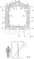
- FIG. 1 A possible embodiment of an air-conditioned building 10 is shown schematically in figs. 1 and 2 and comprises a plurality of first walls 11 configured to define together at least a first compartment 12.
- wall means any constructive element of a building with the function of defining the lateral perimeter, or part of it, the ceiling or the floor.
- the first walls 11 can include for example first lateral walls 11a, at least a first upper wall 11b, or ceiling, and a first lower wall 11c, or floor.
- the air-conditioned building 10 also comprises an air-conditioning apparatus 13 configured to regulate the thermal state of a heat-carrying fluid and to consequently manage the air-conditioning conditions of the air-conditioned building 10.
- the air-conditioning apparatus 13 can be able to manage at least one of either the temperature, the humidity or possibly also the emission speed of the heat-carrying fluid.
- the heat-carrying fluid is heated and cooled by heat exchange, in order to obtain pre-determined thermal/thermal-dynamic conditions.
- the air-conditioning apparatus 13 can be chosen from a group consisting of a heating plant, a cooling plant, a geothermal plant, a solar thermal plant, or possible combinations thereof.
- heat-carrying fluid it can be provided to use air or gas, possibly treated opportunely as will be described hereafter.
- a plurality of second walls 14 are disposed inside the first compartment 12, positioned facing the first walls 11 and distanced from the latter.
- the second walls 14 can include second lateral walls 14a, at least one second upper wall 14b, or ceiling, and at least one second lower wall 14c or floor.
- the second walls 14 are connected to each other so as to define together at least a second compartment 16 which can constitute, for example, one or more rooms of the air-conditioned building 10, or one or more chambers or cells which can be air-conditioned depending on the applicative needs of the application.
- the second walls 14 define a container which is substantially closed on all its sides, whose internal cavity is the second compartment 16.
- a substantially continuous hollow space 15 is defined, in which the air-conditioning apparatus 13 is connected in order to make the heat-carrying fluid circulate inside it.
- substantially continuous hollow space 15 we mean that each hollow space which is defined between the first walls 11 and the second walls 14 is fluidically connected to the adjacent one and there are no interruptions or dividing walls which can interrupt or obstruct the flow of the heat-carrying fluid. That is, the hollow space 15 is comprised between the whole external perimeter development of the container 30 and the first compartment 12 defined by the first walls 11.
- the hollow space 15 is closed on itself between the first walls 11 and the second walls 14.
- the heat-carrying flow hits all the second walls 14 of the second compartment 16 homogeneously, thus guaranteeing a uniform heat exchange on all the second walls 14. Moreover, the heat-carrying flow does not go into the second compartment 16, generating annoying drafts harmful for the people residing in the second compartment 16.
- the hollow space 15 can have a thickness comprised between 10mm and 100mm, preferably between 20 mm and 80 mm, even more preferably about 30 mm.
- the air-conditioning apparatus 13 can comprise a conditioning unit 22 of the heat-carrying fluid and a fluid-dynamic circuit 23 that connects the conditioning unit 22 to the hollow space 15 with a closed-ring circuit.
- the heat-carrying fluid present in the hollow space 15 is constantly re-circulated upon itself and in the hollow space 15 itself, preventing heat losses toward the outside.
- the conditioning unit 22 can comprise, for example, a boiler, one or more electric resistances, a conditioner, a humidifier, a heat pump or possible combinations thereof. Filters for the treatment of the heat-carrying fluid which is introduced into the hollow space 15 can also be associated to the conditioning unit 22.
- the conditioning unit 22 is located outside the hollow space 15 in order to prevent possible contamination of the heat-carrying fluid contained in the hollow space 15 and to prevent the latter from undergoing uncontrolled variations of its thermal state.
- the conditioning unit 22 is located outside at least the first compartment 12, in this case, outside the building 10, and the fluid-dynamic circuit 23 is positioned through, through at least the first walls 11 of the first compartment 12.
- the conditioning unit 22 is located inside the building 10, in this case inside one of the second compartments 16, and the fluid-dynamic circuit 23 connects the conditioning unit 22 to the hollow space 15.
- the first walls 11 or the second walls 14 can be provided with at least two apertures, respectively a first aperture 26 and a second aperture 27 provided to allow the connection of the air-conditioning apparatus 13 with the hollow space 15 and allow the introduction and discharge of the heat-carrying fluid in the latter.
- the first aperture 26 and the second aperture 27 are made in the first walls 11.
- the conditioning unit 22 can be located outside the second compartment 16, in this case outside the building 10, even if it is not excluded that in possible forms of embodiment the conditioning unit 22 is located inside the second compartment 16.
- the first aperture 26 and the second aperture 27 are made in the second walls 14.
- the conditioning unit 22 can be located inside the second compartment 16, as shown in fig. 8 , or outside the second compartment 16.
- the conditioning unit 22 is predisposed to introduce the heat-carrying fluid through the first aperture 26 in a forced way, using ventilators for example, and to aspirate, for example by a depression action, the heat-carrying fluid through the second aperture 27, or vice versa.
- the first aperture 26 is made in a high part of the hollow space 15 while the second aperture 27 is made in a low part of the hollow space 15.
- the first aperture 26 is made in the first upper wall 11b, while the second aperture 27 is made in the first lower wall 11c.
- the first aperture 26 is made in the second upper wall 14b and the second aperture 27 is made in the second lower wall 14c.
- first aperture 26 and the second aperture 27 allows to make the passage and movement conditions of the heat-carrying fluid uniform inside the hollow space 15, and to prevent heat stratification phenomena.
- the fluid-dynamic circuit 23 is connected on one side to the first aperture 26 and on the other side to the second aperture 27 to connect, with a closed circuit, the hollow space 15 to the conditioning unit 22.
- the first aperture 26 and the second aperture 27 are made in a central portion of the surface extension respectively of the at least one first upper wall 11b and of the at least one first lower wall 11c, or of the at least one second upper wall 14b and of the at least one second lower wall 14c.
- the air-conditioning apparatus 13 to generate a flow of heat-carrying fluid that uniformly laps all the walls of the second compartment 16, also those defining a ceiling or a floor of a living space, preventing a direct passage of the heat-carrying fluid from a lower part to an upper part of the second compartment 16.
- the heated heat-carrying fluid is introduced from the first aperture 26 and removed from the second aperture 27.
- the cold heat-carrying fluid is introduced from the second aperture 27 and removed from the first aperture 26.
- Possible implementations of the present invention provide that the first aperture 26 and the second aperture 27 are provided with mouths 28 to connect to the conditioning unit 22.
- An example embodiment of the connection of the mouths 28 to the first aperture 26 and to the second aperture 27 is shown respectively in figs. 3 and 4 .
- the mouths 28 can be served by closing means, manual or automated, which allow to control the flow of heat-carrying fluid through the first aperture 26 and the second aperture 27.
- the flow can be controlled by simple choking or total interception thereof.
- the fluid-dynamic circuit 23 can comprise one or more pipes 25 provided to connect the conditioning unit 22 at least to the first 26 and to the second 27 aperture, possibly by means of the mouths 28, if provided.
- the pipes 25 can be provided, in a known manner, with insulating materials, provided to contain the heat losses to the outside.
- a forced ventilation device 24 can be associated with the conditioning unit 22, provided to move the heat-carrying fluid inside the fluid-dynamic circuit 23 and subsequently inside the hollow space 15, with a determined intensity or speed.
- the speed of the flow of heat-carrying fluid allows to regulate the thermal exchange modalities of the latter with the second walls 14, and consequently of the second walls 14 with the second compartment 16.
- the forced ventilation device 24 can comprise at least one of either a ventilator, a blower, an aspirator or similar or comparable devices and suitable to the purpose.
- the conditioning unit 22 can be served by a commutation member 29 provided to invert the flow of heat-carrying fluid in the fluid-dynamic circuit 23, between the first aperture 26 and the second aperture 27. In this way, depending on the cooling or heating actions of the second compartment 16, it is possible to commutate the delivery and the aspiration of the heat-carrying fluid into or from the hollow space 15, to optimize the flow of the heat-carrying fluid in the latter.
- the commutation member 29 is connected to the forced ventilation device 24 and is configured to invert the direction of feed of the heat-carrying fluid through the first aperture 26 and the second aperture 27. It can be provided for example that the commutation member 29 inverts the movement of the forced ventilation device in order to invert the direction of the feed flow.
- the second walls 14 can be distanced from the first walls 11 by means of spacer elements 17.
- the spacer elements 17 can be attached to the first walls 11 and to the second walls 14 by means of substantially known attachment members such as threaded connections, pins, blocks or suchlike. Other forms of embodiment can provide a connection of the spacer elements 17 by means of glues or adhesive tape for example.
- the spacer elements 17 can extend for at least part of the length of the second walls 14.
- the spacer elements 17 can extend for the entire length of the second walls 14.
- Possible solutions of the present invention can provide that the spacer elements 17 comprise oblong bars disposed parallel to each other and reciprocally distanced on the surface extension of the first 11 and the second 14 walls. In this way it is possible to guarantee the correct positioning of the second walls 14, preventing flection and deformation thereof.
- the portion of hollow space 15 comprised between the first upper walls 11b and the second upper walls 14b, and between the first lower walls 11c and the second lower walls 14c is wider, with respect to the portion of hollow space 15 comprised between the first lateral walls 11a and the second lateral walls 14a.
- the spacer elements 17 connected to the first 11a and to the second lateral walls 14a are less thick than the spacer elements 17 connected to the first 11b and the second upper walls 14b and to the first 11c and the second lower walls 14c.
- the spacer elements 17 associated to the first lateral walls 11a and the second lateral walls 14a that is, to the walls that during use are substantially vertical, are disposed with their longitudinal development in a vertical or sub-vertical direction. This disposition has the function of containing the losses of load of the heat-carrying fluid in transit, and limiting the obstruction effect conferred by the spacer elements 17 in the hollow space 15.
- the spacer elements 17 have a first edge 18 and a second edge 19, opposite the first edge 18 which, when functioning, are disposed resting against the first walls 11 and against the second walls 14 or vice versa.
- the first edge 18 of at least some of the spacer elements 17 is provided on the surface with a plurality of concavities 20 that, in the condition where the spacer elements 17 are attached to the first walls 11 or to the second walls 14, define with the latter corresponding apertures 21 for the passage of the heat-carrying fluid.
- the spacer elements 17 are provided with a plurality of passage apertures made through in the thickness of the spacer element 17.
- apertures 20 allows to make the passage of the heat-carrying fluid in the hollow space 15 uniform and homogeneous, in order to optimize the heat exchange toward the second compartment 16.
- the spacer elements 17 associated with the first walls 11 and the second walls 14, which are vertical during use have the first edge 18 disposed resting against the second walls 14. Thanks to the presence of the concavities 20, this solution allows to reduce the usable contact surface between the spacer elements 17 and the second lateral walls 14a, in practice also reducing the thermal transmission of heat or cold, from the first lateral walls 11a.
- the spacer elements 17 associated with the first upper walls 11b and the second upper walls 14b that is, with the first walls 11 and the second walls 14, during use located in the upper part of the second compartment 16, have the first edge 18 disposed resting against the first walls 11.
- the spacer elements 17 associated with the first lower walls 11c and the second lower walls 14c, or to the first walls 11 and the second walls 14, during use located in the lower part of the second compartment 16, have the first edge 18 resting against the first walls 11. In this way it is possible to obtain a good distribution of heat over the whole surface of the second lower walls 14c. For the same consideration described above, the heat-carrying fluid at a higher temperature will tend to move toward the second lower walls 14c. By disposing the spacer elements 17 with the concavities facing against the first lower walls 11c it is therefore possible to increase the stratification effect of the hot heat-carrying fluid toward the second lower wall 14c.
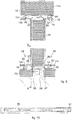
- connection edges between the second upper walls 14b and the second lateral walls 14a are provided with partial obstruction members 31 which from the end edge of the second lateral walls 14a extend in the hollow space 15 toward the first upper walls 11b.
- the partial obstruction members 31 are also connected along the connection edges between the second lower walls 14c and the second lateral walls 14a, and extend from the end edge of the second lateral walls 14a, in the hollow space 15, toward the first lower walls 11c.
- the partial obstruction members 31 comprise a barrier, a blade, a section bar that extends for the whole length of the connection edge between the second lateral walls 14a and the second upper walls 14b and/or the second lower walls 14c.
- the partial obstruction members 31, together with the second upper walls 14b and/or the second lower walls 14c, define box-like cavities 32 open toward the first upper walls 11b and the first lower walls 11c.
- the partial obstruction members 31 define, in the hollow space 15 and with the first upper wall 11b and the first lower wall 11c, a passage gap 33 for the heat-carrying fluid which can be distributed along the first lateral walls 11a and the second lateral walls 14a.
- the box-like cavities 32 allow to obtain a stratification effect of the heat-carrying fluid in correspondence with the surfaces of the second upper walls 14b and/or the second lower walls 14c, in order to optimize the efficiency of heat exchange with the latter and consequently with the ambient of the second compartment 16.
- the second compartment 16 defined by the second walls 14 can be divided into a plurality of rooms 34, in this case shown in the drawings, divided into three rooms 34.
- partition walls 35 in the second compartment 16 configured to determine the division into a plurality of rooms 34.
- the partition walls 35 can be directly connected to the second walls 14 by means of brackets, threaded connection members, pegs, or similar or comparable connection members.
- the partition walls 35 can be directly connected to the first walls 11 passing through the second walls 14 and the hollow space 15.
- the partition walls 35 can be provided with at least a passage aperture 36, in this case a plurality of passage apertures 36, configured to allow the passage through them of the heat-carrying fluid and prevent the interruption of the flow through the hollow space 15.
- the passage apertures 36 can be served by a closing member 37 provided to partly or totally close the passage apertures 36 of the heat-carrying fluid.
- the closing member 37 can be driven manually or automatically.
- the closing member 37 comprises a holed plate, a shutter or occlusion elements able to at least partly regulate the gap of the passage aperture 36.
- An example embodiment of the closing member 37 is shown in fig. 10 , in which the closing member 37 comprises a plate 40 provided with through holes 41 and selectively positionable to modify the passage of the heat-carrying fluid.
- the presence of the closing member 37 allows to regulate the delivery of heat-carrying fluid that laps the second walls 14 and consequently allows to modulate in a desired and differentiated manner the air-conditioning of the rooms 34.
- the position of the closing member 37 is determined by a command and management unit suitable to regulate the entity of choking of the flow of heat-carrying fluid, depending on the temperature set by the user.
- the first walls 11 are provided with structural elements 38, for example, beams and/or pillars, in which the partition walls 35 are connected.
- the structural elements 38 extend toward the hollow space 15 too, in practice interrupting the continuity thereof, it can be provided that these are also provided with through apertures 39 through which to make the heat-carrying fluid circulate.
- the presence of closing members 37 can be provided to regulate the flow of heat-carrying fluid through the hollow space 15.
- the through apertures 39 are located aligned with the passage apertures 36 of the second walls 14.
- the air-conditioned building 10 is provided with several first compartments 12 divided by first lateral walls 11a, in this case having the function of partition walls between the two first compartments. Inside each of the first compartments 12 the second walls 14 are positioned to define respective second compartments 16.
- two hollow spaces 15 are defined in which the heat-carrying fluid is made to flow.
- each hollow space 15 of the second compartments 16 is connected to its own air-conditioning apparatus 13. In this way, by intervening directly on each air-conditioning apparatus 13 it is possible to differentiate the air-conditioning effect of each second compartment 16.
- each hollow space 15 is fluidically connected to the other and to a single air-conditioning apparatus 13.
- the first lateral wall 11a, with the function of partition wall between the second compartments 16, is provided with one or more through apertures 42 provided to put the hollow spaces 15 of the two compartments into fluidic communication.
- closing members 37 are associated with the through apertures 42 and are provided to regulate the flow of heat-carrying fluid from one hollow space 15 to another in a desired way, with a similar function to that described with reference to figs. 8 to 10 .
- the building 10 according to the present invention comprises a single habitable floor 47 in which the two hollow spaces 15 are present located adjacent to each other and on the same habitable floor 47.
- the air-conditioning apparatus 13 is configured to regulate the thermal state only of the heat-carrying fluid present in the hollow spaces 15 of said habitable floor 47.
- the through apertures 42 are made in the thickness of structural elements of the partition wall, in this case in correspondence to a beam of the latter.
- Fig. 13 shows a possible form of embodiment of an air-conditioned building 10 comprising two habitable floors 47, each provided with its own first compartment 12.
- second walls 14 are positioned, provided to define a second compartment 16 for each first compartment 12.
- each of the second compartments 16 partition walls 35 can be provided, as described with reference to figs. 8 , 9 and 10 .
- the hollow spaces 15 are defined for the passage of the heat-carrying fluid.
- each hollow space 15 is connected to its own air-conditioning apparatus 13 provided to regulate the air-conditioning modes of its second compartment 16.
- each hollow space 15 of each habitable floor 47 there is a respective air-conditioning apparatus 13 to regulate the thermal state of the heat-carrying fluid only of one habitable floor 47.
- a respective air-conditioning apparatus 13 to regulate the thermal state of the heat-carrying fluid only of one habitable floor 47.
- the same air-conditioning apparatus 13 is adopted to feed the flow of heat-carrying fluid through both the hollow spaces 15.
- FIG. 14 Another form of embodiment is shown in fig. 14 , in which the construction of an air-conditioned building 10 is provided, according to the present invention, with a gable roof.
- the air-conditioned building comprises a plurality of first walls 11, at least two of which define the first upper walls 11b that are disposed angled with respect to each other according to the inclination of the gables of the roof.
- the first walls 11 together define the first compartment 12 in which the second walls 14 are located, distanced from the first walls 11.
- the second walls 14 also comprise at least two upper walls 14b disposed distanced from the respective first upper walls 11b.
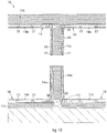
- the first walls 11 can be made in a known way, for example comprising concrete, prefabricated panels, wood panels, thermal and/or acoustic insulating materials, or by-products thereof
- first walls 11 are shown in fig. 5 , in which they comprise an external layer of plaster 43, a first panel 44, a layer of insulating material 45 and a second panel 46.
- the partition walls 35 can also be made in the same way as the first walls 11.
- the layer of insulating material 45 can be made of rockwool, polyurethane foam or other insulating materials.
- first panel 44 and the second panel 46 can be made of wood or by-products of wood, such as for example panels of LDF, MDF, HDF, OSB or suchlike.
- the second walls 14 can be made with panels of plasterboard, plaster fibers, wood or wood by-products.
- first walls 11 or the second walls 14 can be made of a material transparent to visible light, for example glass or plastic materials, such as polycarbonate.
- first transparent wall 11 is located facing at least one second transparent wall 14 in order to allow visibility through them.
- the first walls 11 and the second walls 14, or at least one of them can be made with one or more insulating glass units.
- the air-conditioned building 10 can also include, in a known way, also a bearing structure comprising for example foundations, pillars, support beams or substantially known structural elements.
- the air-conditioned building is provided with one or more detection devices provided to control at least the temperature and humidity of the heat-carrying fluid that circulates through the hollow space 15.
- the detection devices are associated in correspondence to the first aperture 26 and the second aperture 27 provided in the hollow space 15 so as to control the conditions of introduction and expulsion of the heat-carrying fluid into and from the hollow space 15.
- the detection devices comprise at least a detection probe to detect the humidity of the heat-carrying fluid so as to control its conditions.
- the detection devices are provided to detect the ambient conditions of the second compartment 16, and in particular at least one of either temperature or humidity.
- the data detected by the detection devices can be processed by a control and management unit able to suitably command the activation and functioning modes of the air-conditioning apparatus 13 also depending on the particular needs of the users, which can be set for example through a thermostat or a command unit.
- the method for air-conditioning the air-conditioned building 10 provides to make the heat-carrying fluid circulate inside the hollow space 15 in a controlled intensity mode, that is ,speed, temperature and humidity of the flow of heat-carrying fluid.
- the heat-carrying fluid is introduced through the first aperture 26, located in an upper part of the hollow space 15, whereas heat-carrying fluid is taken in from the second aperture 27, in a lower part of the hollow space 15.
- the heat-carrying fluid Due to the action of the convective motions that occur inside the hollow space 15 because of the different temperatures at which the second walls 14 can be found, the heat-carrying fluid generates flows, shown for example in fig. 1 with a continuous-line arrows.
- the heat-carrying fluid transmits heat by conduction to the second walls 14 which in their turn transmit the heat, substantially by irradiation, inside the second compartment 16.
- the heat-carrying fluid is introduced through the second aperture 27 which is disposed in the lower part of the hollow space 15, and heat-carrying fluid contained in the hollow space 15 is taken into the upper part of the latter.
- the plant can have a controlled and automated inverse circulation for a short period.
- the inversion is commanded of the delivery and discharge of the heat-carrying fluid through the first 26 and the second 27 apertures.
- the thermal flux, heat or cold, is distributed homogeneously for the whole surface extension of the second compartment 16, preventing the onset of unwanted air flows inside the compartment which are unpleasant for the people residing there.
- the difference in temperature between the heat-carrying fluid and the ambient temperature of the second compartment 16 is comprised between 2°C and 5°C.
- the method according to the present invention can be efficiently used by means of heat pumps in order to contain air-conditioning costs. From numerous tests carried out it has emerged that the heat-carrying fluid during movement generates an insurmountable barrier in the hollow space 15 that prevents external atmospheric agents from influencing the internal ambient.
- Fig. 15 shows a graph comparing the air-conditioning method according to the present invention, the reference curve for which is curve 1 with a continuous line, and other substantially known air-conditioning methods.
- fig. 15 shows the trends of modes of:
- the air-conditioning mode of the present invention allows to obtain a uniform temperature distribution along the entire height of the room, or of the compartment in which it is adopted.
- Other air-conditioning modes have very variable temperature gradients along the height, for example between floor and ceiling, which as well as generating unwanted air flows, can also cause the generation of humidity or mold on the walls.
Landscapes
- Engineering & Computer Science (AREA)
- Chemical & Material Sciences (AREA)
- Combustion & Propulsion (AREA)
- Mechanical Engineering (AREA)
- General Engineering & Computer Science (AREA)
- Life Sciences & Earth Sciences (AREA)
- Sustainable Development (AREA)
- Devices For Blowing Cold Air, Devices For Blowing Warm Air, And Means For Preventing Water Condensation In Air Conditioning Units (AREA)
- Central Air Conditioning (AREA)
Claims (9)
- Klimatisiertes Bauwerk mit- einer Anzahl von ersten Wänden (11), die dazu eingerichtet sind, zusammen wenigstens einen ersten Raumbereich (12) zu bilden, wobei die ersten Wände (11) erste seitliche Wände (11a), wenigstens eine erste obere Wand (11b) und wenigstens eine der ersten oberen Wand (11b) gegenüberliegende erste untere Wand (11c) umfassen,- einer Anzahl von zweiten Wänden (14), die innerhalb des ersten Raumbereichs (12) angeordnet und miteinander verbunden sind, um wenigstens einen zweiten Raumbereich (16) zu bilden, wobei jede der zweiten Wände (14) wenigstens einer der ersten Wände (11) gegenüberliegend und von dieser beabstandet angeordnet ist, um einen zusammenhängenden Hohlraum (15) zu bilden, der gegen den zweiten Raumbereich (16) abgeschlossen und dazu eingerichtet ist, ein wärmeführendes Fluid aufzunehmen, wobei die zweiten Wände (14) zweite seitliche Wände (14a), wenigstens eine zweite obere Wand (14b) und wenigstens eine zweite untere Wand (14c) umfassen, die jeweils den ersten seitlichen Wänden (11a), der ersten oberen Wand (11b) und ersten unteren Wand (11c) gegenüberliegend angeordnet sind,- einer Klimatisierungsvorrichtung (13), die dazu eingerichtet ist, den thermischen Zustand des wärmeführenden Fluids zu beeinflussen, und die über eine Aufbereitungseinheit (22), die außerhalb des Hohlraums (15) angeordnet ist, und über einen fluiddynamischen Kreislauf (23) verfügt, der den Hohlraum (15) mit der Aufbereitungseinheit (22) in einem geschlossenen Ringkreislauf verbindet, um das wärmeführende Fluid in dem Hohlraum (15) zirkulieren zu lassen und eine thermische Beeinflussung der zweiten Wände (14) bereitzustellen, dadurch gekennzeichnet, dass in der wenigstens einen ersten oberen Wand (11b) oder in der wenigstens einen zweiten oberen Wand (14b) eine erste Ausnehmung (26) und in der wenigstens einen ersten unteren Wand (11c) oder in der wenigstens einen zweiten unteren Wand (14c) eine zweite Ausnehmung (27) eingebracht sind, dass der fluiddynamischen Kreislauf (23) an einer Seite mit der ersten Ausnehmung (26) und mit der anderen an der zweiten Ausnehmung (27) angeschlossen ist, um den Hohlraum (15) in einem geschlossenen Kreislauf mit der Aufbereitungseinheit (22) zu verbinden, und dass die Aufbereitungseinheit (22) durch ein Umschaltteil (29) angesteuert ist, das dazu eingerichtet ist, den Strom an wärmeführendem Fluid in dem fluiddynamischen Kreislauf (23) zwischen der ersten Ausnehmung (26) und der zweiten Ausnehmung (27) umzukehren.
- Klimatisiertes Bauwerk nach Anspruch 1, dadurch gekennzeichnet, dass es ein oder mehrere bewohnbare Geschosse (47) aufweist, dass in einem der Anzahl von bewohnbaren Geschossen (47) der wenigstens eine erste Raumbereich (12), der wenigstens eine zweite Raumbereich (16) und der wenigstens eine Hohlraum (15) vorhanden sind, und dass die Aufbereitungseinheit (22) und der der fluiddynamischen Kreislauf (23) nur an den wenigstens einen Hohlraum (15) eines der bewohnbaren Geschosse (47) angeschlossen sind.
- Bauwerk nach Anspruch 1 oder 2, dadurch gekennzeichnet, dass die erste Ausnehmung (26) und die zweite Ausnehmung (27) in einem mittigen Bereich der Flächenerstreckung jeweils der wenigstens einen ersten oberen Wand (11b) und der wenigstens einen ersten unteren Wand (11c) oder der wenigstens einen zweiten oberen Wand (14b) und der wenigstens einen zweiten unteren Wand (14c) ausgebildet sind.
- Bauwerk nach Anspruch 1, 2 oder 3, dadurch gekennzeichnet, dass der zwischen den ersten oberen Wänden (11b) sowie den zweiten unteren Wänden (14b) und zwischen den ersten unteren Wänden (11c) sowie den zweiten unteren Wänden (14c) Abschnitt des Hohlraums (15) im Vergleich zu dem Teil des Hohlraums (15) zwischen den ersten seitlichen Wänden (11a) und den zweiten seitlichen Wänden (14a) größer ist.
- Bauwerk nach einem der vorangehenden Ansprüche, dadurch gekennzeichnet, dass die zweiten Wände (14) von den ersten Wänden (11) durch Abstandselemente (17), die mit einer Anzahl von sich in deren Dickenrichtung erstreckenden Durchlassausnehmungen ausgebildet sind, auf Abstand gehalten sind.
- Bauwerk nach Anspruch 5, dadurch gekennzeichnet, dass die Abstandselemente (17) längliche Stangen aufweisen, die parallel zueinander und auf der Oberflächenerstreckung der ersten Wände (11) und der zweiten Wände (14) wechselweise beabstandet angeordnet sind.
- Bauwerk nach Anspruch 1, dadurch gekennzeichnet, dass die Verbindungskanten zwischen den zweiten oberen Wänden (14b) und den zweiten seitlichen Wänden (14a) mit Abschnittshemmungsteilen (31) ausgestattet sind, die sich von einer Abschlusskante der zweiten seitlichen Wände (14a) in den Hohlraum (15) in Richtung der ersten oberen Wände (11b) erstrecken, um eine Schichtung des wärmeführenden Fluids zu bewirken.
- Bauwerk nach Anspruch 1 oder 7, dadurch gekennzeichnet, dass die Verbindungskanten zwischen den zweiten unteren Wänden (14c) und den zweiten seitlichen Wänden (14a) mit Abschnittshemmungsteilen (31) ausgestattet sind, die sich von einer Abschlusskante der zweiten seitlichen Wände (14a) in den Hohlraum (15) in Richtung der ersten unteren Wände (11c) erstrecken, um eine Schichtung des wärmeführenden Fluids zu bewirken.
- Verfahren zum Klimatisieren eines Bauwerks, wobei das Bauwerk (10) eine Anzahl von ersten Wänden (11), die dazu eingerichtet sind, wenigstens einen ersten Raumbereich (12) auszubilden, und eine Anzahl von zweiten Wänden (14) umfasst, die innerhalb des ersten Raumbereichs (12) angeordnet und zum Ausbilden wenigstens eines zweiten Raumbereichs (16) miteinander verbunden sind, wobei jede der zweiten Wände (14) wenigstens einem der ersten Wände (11) gegenüberliegend und beabstandet angeordnet sind, um einen zusammenhängenden Hohlraum (15) auszubilden, der in Bezug auf den zweiten Raumbereich (16) abgeschlossen und dazu eingerichtet ist, ein wärmeführendes Fluid aufzunehmen, wobei das Verfahren ein Beeinflussen des thermischen Zustands des wärmeführenden Fluids in dem Hohlraum (15) und das Klimatisieren wenigstens eines klimatisierten Bauwerks (10) aufweist, wobei das Beeinflussen des thermischen Zustands des wärmeführenden Fluids außerhalb des Hohlraums (15) in einer Aufbereitungseinheit (22) erfolgt und wobei das wärmeführende Fluid in dem Hohlraum (15) in einem geschlossenen Ringkreislauf, in einem fluiddynamischen Kreislauf (23) und in der Aufbereitungseinheit (22) zum Durchströmen gebracht wird, um ein thermisches Beeinflussen der zweiten Wände (14) bereitzustellen, dadurch gekennzeichnet, dass im Falle eines durchzuführenden Erwärmens des zweiten Raumbereichs (16) das Verfahren ein Zuführen des wärmeführenden Fluids durch eine einen Zugang zu dem Hohlraum (15) schaffende erste Ausnehmung (26), die in einem oberen Bereich desselben angeordnet ist, und ein Abführen des wärmeführenden Fluids durch eine einen Zugang zu dem Hohlraum (15) schaffende zweite Ausnehmung (27), die in dem unteren Bereich desselben angeordnet ist, bereitstellt, und dass im Falle eines durchzuführenden Abkühlens des zweiten Raumbereichs (12) das Verfahren ein Zuführen des wärmeführenden Fluids durch die zweite Ausnehmung (27) und ein Abführen des wärmeführenden Fluid durch die erste Ausnehmung (26) bereitstellt und für einen Übergang von dem Erwärmungszustand zu dem Kühlzustand oder umgekehrt mittels eines Umschaltteils (29) eine Umkehr der Strömung von wärmeführenden Fluid in dem fluiddynamischen Kreislauf (23) zwischen der ersten Ausnehmung (26) und der zweiten Ausnehmung (27) erfolgt.
Applications Claiming Priority (2)
| Application Number | Priority Date | Filing Date | Title |
|---|---|---|---|
| IT000123A ITUD20130123A1 (it) | 2013-09-30 | 2013-09-30 | Edificio climatizzato e relativo procedimento di climatizzazione di detto edificio |
| PCT/IB2014/064948 WO2015044927A1 (en) | 2013-09-30 | 2014-09-30 | Air-conditioned building and corresponding method to air-condition said building |
Publications (2)
| Publication Number | Publication Date |
|---|---|
| EP3058285A1 EP3058285A1 (de) | 2016-08-24 |
| EP3058285B1 true EP3058285B1 (de) | 2017-11-15 |
Family
ID=49519075
Family Applications (1)
| Application Number | Title | Priority Date | Filing Date |
|---|---|---|---|
| EP14793894.8A Active EP3058285B1 (de) | 2013-09-30 | 2014-09-30 | Klimatisiertes gebäude und entsprechendes verfahren zur klimatisierung des gebäudes |
Country Status (3)
| Country | Link |
|---|---|
| EP (1) | EP3058285B1 (de) |
| IT (1) | ITUD20130123A1 (de) |
| WO (1) | WO2015044927A1 (de) |
Families Citing this family (1)
| Publication number | Priority date | Publication date | Assignee | Title |
|---|---|---|---|---|
| ITUB20160485A1 (it) * | 2016-01-15 | 2017-07-15 | Francesco Asdrubali | Apparecchiatura per l’esecuzione di prove sperimentali |
Family Cites Families (7)
| Publication number | Priority date | Publication date | Assignee | Title |
|---|---|---|---|---|
| JPH09170784A (ja) * | 1995-12-20 | 1997-06-30 | Takenaka Komuten Co Ltd | 空気輻射式冷暖房方法及びその装置 |
| JP3563901B2 (ja) * | 1996-10-31 | 2004-09-08 | 角次 古畑 | 建造物の暖冷房システム |
| JP2001303688A (ja) * | 2000-04-24 | 2001-10-31 | Mitsui Home Co Ltd | 建物の換気システム |
| JP2003042484A (ja) * | 2001-07-31 | 2003-02-13 | Corona Corp | 住宅用空気調和システム |
| JP2003120958A (ja) * | 2001-10-09 | 2003-04-23 | Air Cycle Sangyo Kk | 建物の冷暖房システム |
| JP4586205B2 (ja) * | 2007-12-10 | 2010-11-24 | 森 直樹 | 冷暖気循環構造を有する増築建築物 |
| JP5495914B2 (ja) * | 2010-04-16 | 2014-05-21 | オルガノ株式会社 | 家屋の空調システム |
-
2013
- 2013-09-30 IT IT000123A patent/ITUD20130123A1/it unknown
-
2014
- 2014-09-30 EP EP14793894.8A patent/EP3058285B1/de active Active
- 2014-09-30 WO PCT/IB2014/064948 patent/WO2015044927A1/en not_active Ceased
Non-Patent Citations (1)
| Title |
|---|
| None * |
Also Published As
| Publication number | Publication date |
|---|---|
| ITUD20130123A1 (it) | 2015-03-31 |
| WO2015044927A1 (en) | 2015-04-02 |
| EP3058285A1 (de) | 2016-08-24 |
Similar Documents
| Publication | Publication Date | Title |
|---|---|---|
| EP3194677B1 (de) | Thermische schale, insbesondere für ein gebäude | |
| KR101441189B1 (ko) | 에너지 절감을 위한 환기 벽체 시스템 | |
| CN101191647B (zh) | 空气调节系统 | |
| AU2009232081B2 (en) | Novel sustainable building model | |
| US12352463B2 (en) | Air-conditioning system | |
| JP6920934B2 (ja) | 建物のダブルスキン構造の換気制御システム及び換気制御方法 | |
| HK1214338A1 (zh) | 利用高效空气循环技术综合化的节能建筑物供暖制冷系统 | |
| KR20220040160A (ko) | 냉난방용 복사패널 및 이를 이용한 냉난방 시스템 | |
| EP3058285B1 (de) | Klimatisiertes gebäude und entsprechendes verfahren zur klimatisierung des gebäudes | |
| JP7045710B2 (ja) | 輻射熱利用建築物 | |
| JP2010243142A (ja) | 空調システム及び建物 | |
| Nall et al. | Thermally active floors | |
| JP2016061484A (ja) | 全館冷暖房システム | |
| JP2023024227A (ja) | 建造物 | |
| JP5137599B2 (ja) | 空調システム | |
| JP7503315B2 (ja) | 空調システムの施工方法 | |
| JP2011021417A (ja) | 冷却装置 | |
| JP6221134B2 (ja) | 空調設備 | |
| JP6895667B2 (ja) | 冷暖房システム | |
| Do et al. | Optimizing conditioning systems in the perimeter zones of office buildings | |
| KR20160091606A (ko) | 데이터센터용 에너지절약 항온항습장치 | |
| KR102627792B1 (ko) | 공조 시스템 | |
| JP7432954B2 (ja) | 建造物 | |
| JP3136292B1 (ja) | 空気調和設備 | |
| JPH0215779B2 (de) |
Legal Events
| Date | Code | Title | Description |
|---|---|---|---|
| PUAI | Public reference made under article 153(3) epc to a published international application that has entered the european phase |
Free format text: ORIGINAL CODE: 0009012 |
|
| 17P | Request for examination filed |
Effective date: 20160429 |
|
| AK | Designated contracting states |
Kind code of ref document: A1 Designated state(s): AL AT BE BG CH CY CZ DE DK EE ES FI FR GB GR HR HU IE IS IT LI LT LU LV MC MK MT NL NO PL PT RO RS SE SI SK SM TR |
|
| AX | Request for extension of the european patent |
Extension state: BA ME |
|
| GRAP | Despatch of communication of intention to grant a patent |
Free format text: ORIGINAL CODE: EPIDOSNIGR1 |
|
| INTG | Intention to grant announced |
Effective date: 20170609 |
|
| GRAS | Grant fee paid |
Free format text: ORIGINAL CODE: EPIDOSNIGR3 |
|
| GRAA | (expected) grant |
Free format text: ORIGINAL CODE: 0009210 |
|
| AK | Designated contracting states |
Kind code of ref document: B1 Designated state(s): AL AT BE BG CH CY CZ DE DK EE ES FI FR GB GR HR HU IE IS IT LI LT LU LV MC MK MT NL NO PL PT RO RS SE SI SK SM TR |
|
| AX | Request for extension of the european patent |
Extension state: BA ME |
|
| REG | Reference to a national code |
Ref country code: CH Ref legal event code: EP Ref country code: GB Ref legal event code: FG4D Ref country code: AT Ref legal event code: REF Ref document number: 946671 Country of ref document: AT Kind code of ref document: T Effective date: 20171115 |
|
| REG | Reference to a national code |
Ref country code: IE Ref legal event code: FG4D |
|
| REG | Reference to a national code |
Ref country code: DE Ref legal event code: R096 Ref document number: 602014017345 Country of ref document: DE |
|
| REG | Reference to a national code |
Ref country code: NL Ref legal event code: MP Effective date: 20171115 |
|
| REG | Reference to a national code |
Ref country code: LT Ref legal event code: MG4D |
|
| REG | Reference to a national code |
Ref country code: AT Ref legal event code: MK05 Ref document number: 946671 Country of ref document: AT Kind code of ref document: T Effective date: 20171115 |
|
| PG25 | Lapsed in a contracting state [announced via postgrant information from national office to epo] |
Ref country code: SE Free format text: LAPSE BECAUSE OF FAILURE TO SUBMIT A TRANSLATION OF THE DESCRIPTION OR TO PAY THE FEE WITHIN THE PRESCRIBED TIME-LIMIT Effective date: 20171115 Ref country code: NL Free format text: LAPSE BECAUSE OF FAILURE TO SUBMIT A TRANSLATION OF THE DESCRIPTION OR TO PAY THE FEE WITHIN THE PRESCRIBED TIME-LIMIT Effective date: 20171115 Ref country code: NO Free format text: LAPSE BECAUSE OF FAILURE TO SUBMIT A TRANSLATION OF THE DESCRIPTION OR TO PAY THE FEE WITHIN THE PRESCRIBED TIME-LIMIT Effective date: 20180215 Ref country code: ES Free format text: LAPSE BECAUSE OF FAILURE TO SUBMIT A TRANSLATION OF THE DESCRIPTION OR TO PAY THE FEE WITHIN THE PRESCRIBED TIME-LIMIT Effective date: 20171115 Ref country code: LT Free format text: LAPSE BECAUSE OF FAILURE TO SUBMIT A TRANSLATION OF THE DESCRIPTION OR TO PAY THE FEE WITHIN THE PRESCRIBED TIME-LIMIT Effective date: 20171115 Ref country code: FI Free format text: LAPSE BECAUSE OF FAILURE TO SUBMIT A TRANSLATION OF THE DESCRIPTION OR TO PAY THE FEE WITHIN THE PRESCRIBED TIME-LIMIT Effective date: 20171115 |
|
| PG25 | Lapsed in a contracting state [announced via postgrant information from national office to epo] |
Ref country code: HR Free format text: LAPSE BECAUSE OF FAILURE TO SUBMIT A TRANSLATION OF THE DESCRIPTION OR TO PAY THE FEE WITHIN THE PRESCRIBED TIME-LIMIT Effective date: 20171115 Ref country code: GR Free format text: LAPSE BECAUSE OF FAILURE TO SUBMIT A TRANSLATION OF THE DESCRIPTION OR TO PAY THE FEE WITHIN THE PRESCRIBED TIME-LIMIT Effective date: 20180216 Ref country code: BG Free format text: LAPSE BECAUSE OF FAILURE TO SUBMIT A TRANSLATION OF THE DESCRIPTION OR TO PAY THE FEE WITHIN THE PRESCRIBED TIME-LIMIT Effective date: 20180215 Ref country code: LV Free format text: LAPSE BECAUSE OF FAILURE TO SUBMIT A TRANSLATION OF THE DESCRIPTION OR TO PAY THE FEE WITHIN THE PRESCRIBED TIME-LIMIT Effective date: 20171115 Ref country code: AT Free format text: LAPSE BECAUSE OF FAILURE TO SUBMIT A TRANSLATION OF THE DESCRIPTION OR TO PAY THE FEE WITHIN THE PRESCRIBED TIME-LIMIT Effective date: 20171115 Ref country code: RS Free format text: LAPSE BECAUSE OF FAILURE TO SUBMIT A TRANSLATION OF THE DESCRIPTION OR TO PAY THE FEE WITHIN THE PRESCRIBED TIME-LIMIT Effective date: 20171115 |
|
| PG25 | Lapsed in a contracting state [announced via postgrant information from national office to epo] |
Ref country code: CY Free format text: LAPSE BECAUSE OF FAILURE TO SUBMIT A TRANSLATION OF THE DESCRIPTION OR TO PAY THE FEE WITHIN THE PRESCRIBED TIME-LIMIT Effective date: 20171115 Ref country code: SK Free format text: LAPSE BECAUSE OF FAILURE TO SUBMIT A TRANSLATION OF THE DESCRIPTION OR TO PAY THE FEE WITHIN THE PRESCRIBED TIME-LIMIT Effective date: 20171115 Ref country code: CZ Free format text: LAPSE BECAUSE OF FAILURE TO SUBMIT A TRANSLATION OF THE DESCRIPTION OR TO PAY THE FEE WITHIN THE PRESCRIBED TIME-LIMIT Effective date: 20171115 Ref country code: EE Free format text: LAPSE BECAUSE OF FAILURE TO SUBMIT A TRANSLATION OF THE DESCRIPTION OR TO PAY THE FEE WITHIN THE PRESCRIBED TIME-LIMIT Effective date: 20171115 Ref country code: DK Free format text: LAPSE BECAUSE OF FAILURE TO SUBMIT A TRANSLATION OF THE DESCRIPTION OR TO PAY THE FEE WITHIN THE PRESCRIBED TIME-LIMIT Effective date: 20171115 |
|
| REG | Reference to a national code |
Ref country code: DE Ref legal event code: R097 Ref document number: 602014017345 Country of ref document: DE |
|
| PG25 | Lapsed in a contracting state [announced via postgrant information from national office to epo] |
Ref country code: PL Free format text: LAPSE BECAUSE OF FAILURE TO SUBMIT A TRANSLATION OF THE DESCRIPTION OR TO PAY THE FEE WITHIN THE PRESCRIBED TIME-LIMIT Effective date: 20171115 Ref country code: SM Free format text: LAPSE BECAUSE OF FAILURE TO SUBMIT A TRANSLATION OF THE DESCRIPTION OR TO PAY THE FEE WITHIN THE PRESCRIBED TIME-LIMIT Effective date: 20171115 Ref country code: RO Free format text: LAPSE BECAUSE OF FAILURE TO SUBMIT A TRANSLATION OF THE DESCRIPTION OR TO PAY THE FEE WITHIN THE PRESCRIBED TIME-LIMIT Effective date: 20171115 |
|
| PLBE | No opposition filed within time limit |
Free format text: ORIGINAL CODE: 0009261 |
|
| STAA | Information on the status of an ep patent application or granted ep patent |
Free format text: STATUS: NO OPPOSITION FILED WITHIN TIME LIMIT |
|
| REG | Reference to a national code |
Ref country code: FR Ref legal event code: PLFP Year of fee payment: 5 |
|
| 26N | No opposition filed |
Effective date: 20180817 |
|
| PG25 | Lapsed in a contracting state [announced via postgrant information from national office to epo] |
Ref country code: SI Free format text: LAPSE BECAUSE OF FAILURE TO SUBMIT A TRANSLATION OF THE DESCRIPTION OR TO PAY THE FEE WITHIN THE PRESCRIBED TIME-LIMIT Effective date: 20171115 |
|
| PG25 | Lapsed in a contracting state [announced via postgrant information from national office to epo] |
Ref country code: MT Free format text: LAPSE BECAUSE OF NON-PAYMENT OF DUE FEES Effective date: 20180930 |
|
| PG25 | Lapsed in a contracting state [announced via postgrant information from national office to epo] |
Ref country code: TR Free format text: LAPSE BECAUSE OF FAILURE TO SUBMIT A TRANSLATION OF THE DESCRIPTION OR TO PAY THE FEE WITHIN THE PRESCRIBED TIME-LIMIT Effective date: 20171115 |
|
| PG25 | Lapsed in a contracting state [announced via postgrant information from national office to epo] |
Ref country code: PT Free format text: LAPSE BECAUSE OF FAILURE TO SUBMIT A TRANSLATION OF THE DESCRIPTION OR TO PAY THE FEE WITHIN THE PRESCRIBED TIME-LIMIT Effective date: 20171115 |
|
| PG25 | Lapsed in a contracting state [announced via postgrant information from national office to epo] |
Ref country code: HU Free format text: LAPSE BECAUSE OF FAILURE TO SUBMIT A TRANSLATION OF THE DESCRIPTION OR TO PAY THE FEE WITHIN THE PRESCRIBED TIME-LIMIT; INVALID AB INITIO Effective date: 20140930 Ref country code: MK Free format text: LAPSE BECAUSE OF NON-PAYMENT OF DUE FEES Effective date: 20171115 |
|
| PG25 | Lapsed in a contracting state [announced via postgrant information from national office to epo] |
Ref country code: AL Free format text: LAPSE BECAUSE OF FAILURE TO SUBMIT A TRANSLATION OF THE DESCRIPTION OR TO PAY THE FEE WITHIN THE PRESCRIBED TIME-LIMIT Effective date: 20171115 Ref country code: IS Free format text: LAPSE BECAUSE OF FAILURE TO SUBMIT A TRANSLATION OF THE DESCRIPTION OR TO PAY THE FEE WITHIN THE PRESCRIBED TIME-LIMIT Effective date: 20180315 |
|
| PGFP | Annual fee paid to national office [announced via postgrant information from national office to epo] |
Ref country code: IE Payment date: 20200918 Year of fee payment: 7 Ref country code: LU Payment date: 20200923 Year of fee payment: 7 Ref country code: GB Payment date: 20200921 Year of fee payment: 7 Ref country code: FR Payment date: 20200914 Year of fee payment: 7 Ref country code: DE Payment date: 20200925 Year of fee payment: 7 Ref country code: MC Payment date: 20200922 Year of fee payment: 7 |
|
| PGFP | Annual fee paid to national office [announced via postgrant information from national office to epo] |
Ref country code: CH Payment date: 20200921 Year of fee payment: 7 Ref country code: BE Payment date: 20200925 Year of fee payment: 7 |
|
| REG | Reference to a national code |
Ref country code: DE Ref legal event code: R119 Ref document number: 602014017345 Country of ref document: DE |
|
| REG | Reference to a national code |
Ref country code: CH Ref legal event code: PL |
|
| REG | Reference to a national code |
Ref country code: BE Ref legal event code: MM Effective date: 20210930 |
|
| GBPC | Gb: european patent ceased through non-payment of renewal fee |
Effective date: 20210930 |
|
| PG25 | Lapsed in a contracting state [announced via postgrant information from national office to epo] |
Ref country code: MC Free format text: LAPSE BECAUSE OF NON-PAYMENT OF DUE FEES Effective date: 20210930 |
|
| PG25 | Lapsed in a contracting state [announced via postgrant information from national office to epo] |
Ref country code: LU Free format text: LAPSE BECAUSE OF NON-PAYMENT OF DUE FEES Effective date: 20210930 Ref country code: IE Free format text: LAPSE BECAUSE OF NON-PAYMENT OF DUE FEES Effective date: 20210930 Ref country code: GB Free format text: LAPSE BECAUSE OF NON-PAYMENT OF DUE FEES Effective date: 20210930 Ref country code: FR Free format text: LAPSE BECAUSE OF NON-PAYMENT OF DUE FEES Effective date: 20210930 Ref country code: DE Free format text: LAPSE BECAUSE OF NON-PAYMENT OF DUE FEES Effective date: 20220401 Ref country code: BE Free format text: LAPSE BECAUSE OF NON-PAYMENT OF DUE FEES Effective date: 20210930 |
|
| PG25 | Lapsed in a contracting state [announced via postgrant information from national office to epo] |
Ref country code: LI Free format text: LAPSE BECAUSE OF NON-PAYMENT OF DUE FEES Effective date: 20210930 Ref country code: CH Free format text: LAPSE BECAUSE OF NON-PAYMENT OF DUE FEES Effective date: 20210930 |
|
| P01 | Opt-out of the competence of the unified patent court (upc) registered |
Effective date: 20230601 |
|
| PGFP | Annual fee paid to national office [announced via postgrant information from national office to epo] |
Ref country code: IT Payment date: 20230728 Year of fee payment: 10 |
|
| PG25 | Lapsed in a contracting state [announced via postgrant information from national office to epo] |
Ref country code: IT Free format text: LAPSE BECAUSE OF NON-PAYMENT OF DUE FEES Effective date: 20240930 |