EP3056880B1 - Spectromètre compact - Google Patents
Spectromètre compact Download PDFInfo
- Publication number
- EP3056880B1 EP3056880B1 EP15175050.2A EP15175050A EP3056880B1 EP 3056880 B1 EP3056880 B1 EP 3056880B1 EP 15175050 A EP15175050 A EP 15175050A EP 3056880 B1 EP3056880 B1 EP 3056880B1
- Authority
- EP
- European Patent Office
- Prior art keywords
- birefringent
- optics
- light
- birefringent plate
- diffuser
- Prior art date
- Legal status (The legal status is an assumption and is not a legal conclusion. Google has not performed a legal analysis and makes no representation as to the accuracy of the status listed.)
- Active
Links
- 230000003595 spectral effect Effects 0.000 claims description 97
- 230000003287 optical effect Effects 0.000 claims description 20
- 230000005540 biological transmission Effects 0.000 claims description 3
- 239000010410 layer Substances 0.000 description 89
- 239000000463 material Substances 0.000 description 14
- 238000012545 processing Methods 0.000 description 12
- 230000010287 polarization Effects 0.000 description 10
- 238000000034 method Methods 0.000 description 8
- 238000012935 Averaging Methods 0.000 description 5
- 238000004458 analytical method Methods 0.000 description 5
- 238000005259 measurement Methods 0.000 description 5
- 239000013078 crystal Substances 0.000 description 4
- 238000001228 spectrum Methods 0.000 description 4
- 238000013461 design Methods 0.000 description 3
- 238000012544 monitoring process Methods 0.000 description 3
- 239000012925 reference material Substances 0.000 description 3
- 238000002835 absorbance Methods 0.000 description 2
- 238000000701 chemical imaging Methods 0.000 description 2
- 239000003795 chemical substances by application Substances 0.000 description 2
- 238000003384 imaging method Methods 0.000 description 2
- 238000012986 modification Methods 0.000 description 2
- 230000004048 modification Effects 0.000 description 2
- 239000000700 radioactive tracer Substances 0.000 description 2
- 239000002356 single layer Substances 0.000 description 2
- 229910021532 Calcite Inorganic materials 0.000 description 1
- 241001050985 Disco Species 0.000 description 1
- 238000007792 addition Methods 0.000 description 1
- 239000003086 colorant Substances 0.000 description 1
- 238000004737 colorimetric analysis Methods 0.000 description 1
- 230000000052 comparative effect Effects 0.000 description 1
- 230000001419 dependent effect Effects 0.000 description 1
- 238000010586 diagram Methods 0.000 description 1
- 230000008030 elimination Effects 0.000 description 1
- 238000003379 elimination reaction Methods 0.000 description 1
- 238000005516 engineering process Methods 0.000 description 1
- 230000007613 environmental effect Effects 0.000 description 1
- 239000003344 environmental pollutant Substances 0.000 description 1
- 238000005286 illumination Methods 0.000 description 1
- 231100000719 pollutant Toxicity 0.000 description 1
- WYOHGPUPVHHUGO-UHFFFAOYSA-K potassium;oxygen(2-);titanium(4+);phosphate Chemical compound [O-2].[K+].[Ti+4].[O-]P([O-])([O-])=O WYOHGPUPVHHUGO-UHFFFAOYSA-K 0.000 description 1
- 238000003908 quality control method Methods 0.000 description 1
- 239000000126 substance Substances 0.000 description 1
Images


Classifications
-
- G—PHYSICS
- G01—MEASURING; TESTING
- G01J—MEASUREMENT OF INTENSITY, VELOCITY, SPECTRAL CONTENT, POLARISATION, PHASE OR PULSE CHARACTERISTICS OF INFRARED, VISIBLE OR ULTRAVIOLET LIGHT; COLORIMETRY; RADIATION PYROMETRY
- G01J3/00—Spectrometry; Spectrophotometry; Monochromators; Measuring colours
- G01J3/02—Details
- G01J3/0272—Handheld
-
- G—PHYSICS
- G01—MEASURING; TESTING
- G01J—MEASUREMENT OF INTENSITY, VELOCITY, SPECTRAL CONTENT, POLARISATION, PHASE OR PULSE CHARACTERISTICS OF INFRARED, VISIBLE OR ULTRAVIOLET LIGHT; COLORIMETRY; RADIATION PYROMETRY
- G01J3/00—Spectrometry; Spectrophotometry; Monochromators; Measuring colours
- G01J3/28—Investigating the spectrum
- G01J3/447—Polarisation spectrometry
-
- G—PHYSICS
- G01—MEASURING; TESTING
- G01J—MEASUREMENT OF INTENSITY, VELOCITY, SPECTRAL CONTENT, POLARISATION, PHASE OR PULSE CHARACTERISTICS OF INFRARED, VISIBLE OR ULTRAVIOLET LIGHT; COLORIMETRY; RADIATION PYROMETRY
- G01J3/00—Spectrometry; Spectrophotometry; Monochromators; Measuring colours
- G01J3/02—Details
- G01J3/0202—Mechanical elements; Supports for optical elements
-
- G—PHYSICS
- G01—MEASURING; TESTING
- G01J—MEASUREMENT OF INTENSITY, VELOCITY, SPECTRAL CONTENT, POLARISATION, PHASE OR PULSE CHARACTERISTICS OF INFRARED, VISIBLE OR ULTRAVIOLET LIGHT; COLORIMETRY; RADIATION PYROMETRY
- G01J3/00—Spectrometry; Spectrophotometry; Monochromators; Measuring colours
- G01J3/02—Details
- G01J3/0205—Optical elements not provided otherwise, e.g. optical manifolds, diffusers, windows
- G01J3/0229—Optical elements not provided otherwise, e.g. optical manifolds, diffusers, windows using masks, aperture plates, spatial light modulators or spatial filters, e.g. reflective filters
-
- G—PHYSICS
- G01—MEASURING; TESTING
- G01J—MEASUREMENT OF INTENSITY, VELOCITY, SPECTRAL CONTENT, POLARISATION, PHASE OR PULSE CHARACTERISTICS OF INFRARED, VISIBLE OR ULTRAVIOLET LIGHT; COLORIMETRY; RADIATION PYROMETRY
- G01J3/00—Spectrometry; Spectrophotometry; Monochromators; Measuring colours
- G01J3/02—Details
- G01J3/0256—Compact construction
-
- G—PHYSICS
- G01—MEASURING; TESTING
- G01J—MEASUREMENT OF INTENSITY, VELOCITY, SPECTRAL CONTENT, POLARISATION, PHASE OR PULSE CHARACTERISTICS OF INFRARED, VISIBLE OR ULTRAVIOLET LIGHT; COLORIMETRY; RADIATION PYROMETRY
- G01J3/00—Spectrometry; Spectrophotometry; Monochromators; Measuring colours
- G01J3/28—Investigating the spectrum
- G01J3/45—Interferometric spectrometry
- G01J3/453—Interferometric spectrometry by correlation of the amplitudes
- G01J3/4531—Devices without moving parts
-
- G—PHYSICS
- G01—MEASURING; TESTING
- G01J—MEASUREMENT OF INTENSITY, VELOCITY, SPECTRAL CONTENT, POLARISATION, PHASE OR PULSE CHARACTERISTICS OF INFRARED, VISIBLE OR ULTRAVIOLET LIGHT; COLORIMETRY; RADIATION PYROMETRY
- G01J3/00—Spectrometry; Spectrophotometry; Monochromators; Measuring colours
- G01J3/28—Investigating the spectrum
- G01J3/45—Interferometric spectrometry
- G01J3/453—Interferometric spectrometry by correlation of the amplitudes
- G01J3/4532—Devices of compact or symmetric construction
-
- G—PHYSICS
- G01—MEASURING; TESTING
- G01J—MEASUREMENT OF INTENSITY, VELOCITY, SPECTRAL CONTENT, POLARISATION, PHASE OR PULSE CHARACTERISTICS OF INFRARED, VISIBLE OR ULTRAVIOLET LIGHT; COLORIMETRY; RADIATION PYROMETRY
- G01J3/00—Spectrometry; Spectrophotometry; Monochromators; Measuring colours
- G01J3/46—Measurement of colour; Colour measuring devices, e.g. colorimeters
-
- G—PHYSICS
- G02—OPTICS
- G02B—OPTICAL ELEMENTS, SYSTEMS OR APPARATUS
- G02B27/00—Optical systems or apparatus not provided for by any of the groups G02B1/00 - G02B26/00, G02B30/00
- G02B27/28—Optical systems or apparatus not provided for by any of the groups G02B1/00 - G02B26/00, G02B30/00 for polarising
- G02B27/283—Optical systems or apparatus not provided for by any of the groups G02B1/00 - G02B26/00, G02B30/00 for polarising used for beam splitting or combining
Definitions
- This invention relates to spectrometers, and more particular to improved Fourier transform spectrometers suitable for use with digital cameras including cameras used in mobile devices.
- a spectrometer is an instrument used to measure properties of light over a specific portion of the electromagnetic spectrum, typically used to identify materials.
- the variable measured can be the light's spectral intensity or irradiance.
- Fourier transform spectrometers can be used for visible, infrared and ultraviolet frequencies, and are based on two-beam interference or polarization modulation phenomenon to generate a resulting interferogram. The Fourier transform of a resulting interferogram corresponds to the spectral signature of incoming light.
- Phua et al discloses an advanced hyperspectral imaging device which provides spectral signatures of every point of a 2D image.
- a cascade of birefringent plates are used to generate linear (or curved) fringes which are relatively easy to process.
- Phua et al is an elegant device which greatly simplifies optics required for generation of interferograms, the device requires scanning, that is, a large plurality of images have to be taken.
- Extensive computational processing is also needed to process the large plurality of images to give the spectral signatures of every point of the image.
- the large processing requirements for such a hyperspectral imaging device will not work well with digital cameras, especially those found in mobile devices. This is due in part to the relatively limited processing power available in mobile devices. Further, jitter during scanning will lead to the introduction of high spectral inaccuracies.
- spectrometers are relatively difficult to use with field work outside of a lab, and they are typically much more expensive, require frequent spectral recalibration, require several display/control/ power accessories before the spectrometer can function properly, and are simply too bulky and inconvenient to carry around while running a daily routine.
- spectrometers although highly useful analytical instruments, have seen limited adoption by the general public and are normally restricted to lab work. It would be desirable to provide a spectrometer which is small enough to be used with existing digital cameras, especially those incorporated into conventional mobile devices, and which is lightweight and convenient enough to carry around while running a daily routine.
- spectrometer which does not require mechanical scanning, and which can capture a spectral signature of an object in a single snapshot while only requiring the simple processing power that mobile devices can handle while still maintaining a high level of spectral fidelity to allow for accurate and rapid analysis.
- US2012268745 discloses snapshot imaging Fourier transform spectrometers which include a lens array that produces sub-images that are directed through a birefringent interferometer in orthogonal polarization eigenstates that acquire an optical path difference. Interference patterns based on this OPD can be Fourier transformed to obtain a spectral image.
- polarizing gratings provide a spatial heterodyne frequency and offset the spectra.
- the present disclosure provides an optical spectrometer for measuring a spectral signature of an object as recited in claim 1. Further advantageous features are recited in the dependent claims.
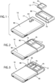
- Fig. 1 is an isometric view of a spectrometer 10 in accordance with one embodiment suitable for use in conjunction with a standard digital camera 65 incorporated into a conventional mobile phone 90.
- Compact spectrometers such as those disclosed herein may be used to obtain the spectral signature of an object, and can be used in a wide variety of applications, such as, for example, colorimetry applications, environmental monitoring, chemicals analysis, material analysis and identification, pollutants monitoring, monitoring of crops, mineralogy identification, spectral applications in industrial automation, medical diagnostics and forensic applications.
- Other uses for the compact spectrometers disclosed herein will be readily apparent to those skilled in the art given the benefit of this disclosure.
- the spectrometer 10 is compact and lightweight with a remarkably small footprint.
- the spectrometer 10 comprises fringe generating optics 12 which are comprised of front optics 45 and birefringent optics 55.
- Light reflected from or generated by the object whose spectral signature is to be measured passes sequentially through the front optics 45 to the birefringent optics 55, and from there to the camera 65, typically a digital camera incorporated into a mobile device, here a mobile phone 90.
- Mobile devices are understood herein to refer broadly to mobile phones, tablets, laptops, etc., and even pcs in some applications.
- the digital camera generates a signal based on the images it receives and in turn relays that signal to a processor, which generates the spectral signature.
- the size of the fringe generating optics 12 is preferably sufficiently large enough to cover the entire aperture of camera 65, but need not be any larger. Moreover, a thickness of the fringe generating optics is sufficiently small that the device will easily fit in a pocket in much the same was as a conventional mobile phone fits.
- the processors typically found in the phone 90 are sufficient for purposes of calculating the spectral signature of the object using the spectrometer disclosed herein. The spectral signature and related control interface can be displayed and controlled on existing display panel of the mobile device without requiring additional control and power management accessories.
- the fringe generating optics 12 may be positioned in a housing 80. Further, the fringe generating optics 12 may be adjustable between an operational position ( Fig. 2 ) where the fringe generating optics 12 are positioned in front of the camera 65, to a nonoperational position ( Fig. 3 ) where the camera can function in the normal manner.
- the housing 80 is an external attachment adapted to be placed on the mobile device, and is shown in this embodiment as band shaped, extending around the phone 90 and defining a run channel 70.
- the fringe generating optics 12 is slidable in the run channel 70 between positions.
- the housing 80 may be formed as part of a device cover (not shown), and the fringe generating optics may be rotated between the operational and the nonoperational positions.
- the housing 80 may also be built into the mobile device.
- the spectrometer works best with the object relatively close to the fringe generating optics/mobile device so that the light reflected is primarily from the object.
- Light from the object is understood herein to mean typically light reflected off the surface of the object or light emitted by the object or light transmitted through the object whose spectral signature is sought. Having a consistent and uniform source of light illuminating the object is valuable in terms of normalizing the measured spectral signatures to obtain the object's spectral reflectance or spectral absorbance.
- a flash light or light source 77 is almost always provided and the light source is made with high quality control, so the light source is relatively consistent from phone to phone.
- the light source 77 is normally designed to provide a relatively uniform light source at some distance from the camera, and that distance is typically greater than the normal operating distance for obtaining spectral signatures. Therefore, the fringe generating optics may optionally be provided with a light diffuser 75 as shown in Figs. 1-3 .
- the light diffuser 75 would be positioned in front of the flash 77 when the fringe generating optics 12 (front optics 45 and birefringent optics 55) are positioned in front of the camera, and thereby make the light or flash shone on the object relatively uniform and consistent.
- the light diffuser 75 may also incorporate a light guide (not shown) before diffusing the light for a more uniform and consistent illumination on the object.
- the spectrometer may also provide a reference reflectance material or surface as a built-in or external accessory to perform calibration on the spectral signature of the flash 77.
- Fig. 4 is a simple schematic showing the preferred order when the fringe generating optics 12 are in the operational position.
- Light passes through the front optics 45, to the birefringent optics 55, and from there to the camera 65.
- the camera generates a signal and relays that signal to a processor which generates the spectral signature of the object in the manner described in greater detail below.
- Fig. 5 shows one embodiment of the front optics 45 formed as a single layer optical diffuser 40.
- the diffuser 40 can comprise any material which acts to homogenize or scatter background light received.
- the diffuser 40 can comprise a rough ground translucent layer separate from the birefringent optics 55, positioned immediately adjacent the birefringent optics.
- the diffuser 40 may also be formed as a rough ground front surface of the first polarizer 20 of the birefringent optics 55.
- the diffuser 40 can also be a micro-lens lenticular sheet or micro-lens lenticular array to scatter and homogenize light received before entering the birefringent optics 55.
- front optics 45 and birefringent optics 55 may be contained in a frame 76.
- the frame 76 may be slidable in the run channel as noted above.
- the simple diffuser used as the front optic 45 in Fig. 5 makes the spectrometer implementation very low cost, compact and relatively immune to any optical misalignment.
- the diffuser 40 acts to homogenize the background so that a fringe image generated by the birefringent optics 55 and captured by camera 65 is principally providing the spectral signature of the object.
- a fringe image generated by the birefringent optics 55 and captured by camera 65 is principally providing the spectral signature of the object.
- the uniform background advantageously also allows simple direct Fourier transform of the interferogram to give the spectral signatures without the complex processing algorithms required in Phua et al. This means that a spectral signature can now be obtained simply and quickly by using the processing power of existing mobile devices.
- a uniform background a single fringe image, as shown in either of Fig.
- Fig. 12 can advantageously provide a large plurality of single interferograms (easily more than a thousand) whose Fourier transform gives the spectral signatures of the object. By taking the average of this large number of spectral signatures, a high quality spectral signature of the object with significantly reduced noise can be obtained.
- the embodiment in Fig. 5 measures the spectral signatures of the light homogenized by the diffuser 40, it works well when the object-of-interest is relatively close, most preferably less than a few centimeters from the fringe generating optics/mobile device.
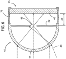
- the embodiment in Fig. 6 gives some directionality in the measurement and allows the spectrometer to aim and measure spectral signatures of objects that are farther away, for example, as far as a few meters.
- the front optics 45 is formed as an additional focusing lens 44 and a mask 42 that defines an aperture 43 which limits the amount of light which is passed onto the diffuser 40.
- the aperture 43 is spaced apart from a diffuser 40 by a distance 47.
- Tracer rays show how this embodiment would limit light 49 coming in from the sides, usually away from the object whose spectral signature is sought.
- the distance 47 is preferably set so that the area covered by the tracer rays at the diffuser 40 is larger than the cross-sectional area of the aperture of the camera 65.
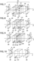
- Fig. 7 shows a schematic optical layout of one embodiment of the birefringent optics 55 of the compact spectrometer. Light reflected from the object whose spectral signature is desired projects through the front optics 45 and has an optical axis which extends along a Z-axis. The Z-axis is a horizontal axis in the plane of the paper as shown in Fig. 7 .
- the light passes through a first polariser 20 which has a first polarisation angle 21.
- the polarisation angle 21 is shown to be formed in an X-Y plane.
- the X-Y plane is generally perpendicular to the Z-axis (the direction of light transmission through the birefringent optics 55, from front optics 45 to digital camera 65) as shown in Fig. 7 .
- the polariser transmits light linearly polarised at the polarisation angle in the X-Y plane.
- the polariser angle may be 45° with respect to the X-axis.
- the light passes through the polariser is a linearly polarised beam which is transmitted to a first birefringent layer 22 having a first optic axis 23 formed at a first angle, then to a second birefringent layer 24 having a second optic axis 29 formed at a second angle, and then to a second polariser (sometimes referred to as an analyzer) 26.
- the birefringent layers 22, 24 may be formed of calcite, for example.
- the birefringent optics cooperate to produce an image of regular curved fringes of Fig. 12 which are projected through a lens which focuses the light onto a -detector array of the digital camera 65 of the mobile device.
- the second polariser 26 has a second polariser angle 31 which is related to the polariser angle 21.
- the second polariser angle is either the same as the first polariser angle with respect to the X-axis or at a 90° angle with respect to the first polariser angle for maximum fringe contrast.
- the first polariser angle 21 can be 45° or -45° with respect to the X-axis and the second polariser angle 31 may be either ⁇ 45° with respect to the X-axis.
- the linearly polarised light After passing through the first polariser 20, the linearly polarised light passes through the first birefringent layer 22, causing the light to be split into two beams that are orthogonal components of the polarised light. These components are sometimes referred to as the extraordinary ray or e-ray and ordinary ray or o-ray.
- the e-ray and the o-ray have different refractive indices. While the o-ray refractive index is constant and independent of the direction of light propagation, the refractive index of e-ray varies with the direction of light propagation. Consequently, one ray travels faster than the other through the layer 22 resulting in a phase difference between the e-ray and o-ray.
- the resulting phase difference is a function of several properties of the layer 22 and the light, including the propagation direction of e-ray and o-ray within the layer 22, a cut angle of the layer 22 with respect to the first optic axis 23, an angle between a plane containing the first optic axis 23 and a plane of incidence of the light, a wavelength of the polarised light, a thickness 25 of the layer and a material of layer 22.
- This phase difference varies with the angle of incidence of light into the birefringent optics 55.
- the first birefringent layer 22 is positioned between the first polariser 20 and the second birefringent layer 24 such that the e-ray and o-ray exit the first birefringent layer 22 and immediately enter the second birefringent layer 24.
- the birefringent layers 22, 24 are in direct contact with one another.
- the second birefringent layer 24 has a second optic angle 29 which is related to the first angle 23.
- the second birefringent layer 24 compensates for the phase difference generated by the first birefringent layer 22 by having a slow axis of the second birefringent layer orthogonal to a slow axis of the first birefringent layer.
- the amount of phase difference compensated in the second birefringent layer is a function of several properties of the layer 24 and the light, including the propagation direction of e-ray and o-ray within the layer 24, a cut angle of the layer 24 with respect to the second optic axis 29, a wavelength of the polarised light, a thickness 27 of the layer and a material of layer 24.
- Fig. 7 upon exiting the second birefringent layer 24, there will be a net phase difference that varies with the angle of incidence of light into the birefringent optics which creates polarization modulation of the light.
- this light is analyzed by the second polarizer 26, it creates a modulation of the transmitted light intensity with the angle of incidence. This intensity modulation manifests as curved fringes in the image detected by camera 65 as shown in Fig. 12 .
- the first optic axis 23 of the first birefringent layer 22 lies at an angle from the X-axis in an X-Z plane, where the X-Z plane is defined by the X-axis and the Z-axis and the Z-axis is the direction of propagation of light through the birefringent optics.
- the first optic angle is between -90° to 90° from the X-axis, and more preferably at ⁇ 45° from the X-axis, since this angle is associated with generation of fringes that minimize the layer thickness and also allow for reduced computational processing.
- the second optic axis 29 of the second birefringent layer 24 is within ⁇ 20° of the Y-axis, and more preferably perpendicular to the Z-axis and along the Y-axis. This can also be expressed as at a 90° angle with respect to the X-axis or Z-axis.
- the second optic angle 29 is in a plane orthogonal to the first optic angle 23 and in a plane perpendicular to the Z-axis.
- the first optic angle of 45° and a second optic angle of 90° is associated with generation of fringes that minimize the layer thickness, and allow for reduced computational processing and as such is preferred.
- both layers 22 and 24 have positive birefringence, such that the velocity of the ordinary ray is greater than that of the extraordinary ray.
- a first optic angle of 45° and a second optic angle of 90° is recited in this embodiment, a similar result can be achieved with other angles by adjusting thicknesses 25, 27 or material selection of the layers 22, 24 respectively.
- the thickness 25 of the positive first birefringent layer 22 is different from (larger) than the thickness 27 of the positive second birefringent layer 24 and both crystals can be made of the same or different birefringent materials of positive birefringence.
- a positive first birefringent layer 22 can have an optic axis lying in the X-Z plane at -45° from the X-axis.
- the corresponding second birefringent layer 24 has the same second angle as described in the paragraph immediately above, and has positive birefringence. If the birefringence of the first layer 22 is switched to negative birefringence then the birefringence of the second layer 24 is similarly switched to negative. Both layers have the same birefringence merely in the sense that they have the same sign of birefringence, more specifically, both are either positive or negative.
- the second thickness 27 is less than the first thickness 25.
- Fig. 8 illustrates a schematic of optical layout of another embodiment where the first birefringent layer 22 and the second birefringent layer 124 are of different materials.
- the layers 22, 124 have opposite birefringence merely in the sense that when one is positive the other is negative.
- the optic axis of the first birefringent layer 22 lies in the X-Z plane and the optic axis of the second birefringent layer 124 lies in the X-Z plane as well.
- the first angle 23 may be the same as the second angle 129 in magnitude but in an opposite sign with respect to the X-axis.
- the first layer 22 has positive birefringence and the second layer 124 has negative birefringence.
- the first optic angle 23 is between -90° to 90° and the second optic angle 129 is between 90° to -90° from the X-axis, and more preferably they are at ⁇ 45° from the X-axis as shown in Fig. 8 , since this angle is associated with generation of fringes that minimize the layer thickness, also allow for reduced computational processing and as such is preferred.
- the birefringence of the layers may be switched such that the first layer 22 has negative birefringence and the second layer 124 has positive birefringence. Since the layers 22, 124 comprise different materials, a chirp is introduced in the resulting signal. The chirp advantageously helps reduce a dynamic range required to improve signal-to-noise ratio.
- the thickness 25 of the first birefringent layer 22 is different from the thickness 127 of the positive second birefringent layer 124.
- the linearly polarised beam from the polariser enters the first birefringent layer 22 and is split into two polarization components - the o-ray and the e-ray.
- the e-ray and the o-ray Upon exiting the first birefringent layer, the e-ray and the o-ray enter the second birefringent layer 124.
- the e-ray in the first birefringent layer remains an e-ray in the second birefringent layer.
- the o-ray in the first birefringent layer remains an o-ray in the second birefringent layer.
- This phase difference varies with the angle of incidence of light into birefringent optics 55 and creates polarization modulation of the light.
- this light is analyzed by the second polarizer 26, it creates a modulation of the transmitted light intensity with the angle of incidence. This intensity modulation manifests as the line fringes in the interferogram shown in Fig. 11 when detected by camera 65.
- Fig. 9 discloses another embodiment of the birefringent optics 55.
- the same birefringent material is used for birefringent plates 22, 224 and the plates have the same optic axes 23, 229 as the second embodiment of Fig. 8 , but the plates have equal thicknesses 25, 227.
- the first optic angle 23 is between -90° to 90° and the second optic angle 229 is between 90° to -90° from the X-axis, and more preferably they are at ⁇ 45° from the X-axis, since these angles are associated with generation of fringes that minimize the layer thickness, allow for reduced computational processing and as such is preferred.
- a 1 ⁇ 2 wave plate or retarder 50 is used to switch the polarisation of linearly polarised light.
- the retarder 50 is positioned between the two birefringent layers 22, 224.
- the first birefringent plate, 1 ⁇ 2 wave plate and second birefringent layers are sandwiched together, as shown in Fig. 9 .
- the linearly polarised beam from the first polariser 20 enters the first birefringent layer 22 and is split into two polarization components - the o-ray and the e-ray.
- the e-ray and the o-ray Upon exiting the first birefringent layer, the e-ray and the o-ray enter the retarder 50 and they are switched in polarization so that the e-ray in the first birefringent layer 22 become the o-ray when it enters the second birefringent layer 224. Likewise, the o-ray in the first birefringent layer 22 become the e-ray in the second birefringent layer 224.
- there will be a net phase difference between the e-ray and the o-ray This phase difference varies with the angle of incidence of light into the birefringent optics 55 and it creates polarization modulation of the light. When this light is analyzed by the second polarizer 26, it creates a modulation of the transmitted light intensity with the angle of incidence. This intensity modulation manifests as straight line fringes, again as shown in Fig.11 , in the image detected by camera 65.
- Fig. 10 discloses another example of the birefringent optics 55 which does not form part of the invention.
- the first three representative embodiments of the birefringent optics can be constructed using either uniaxial or biaxial birefringent crystals, in the embodiment of Fig. 10 only a biaxial birefringent crystal is used.
- a single birefringent plate 122 is used for the birefringent optics 55.
- This single birefringent layer 122 is constructed using a biaxial birefringent crystal such as Potassium Titanyl Phosphate (KTP), for example. Both optic axes of the birefringent layer 122 lie in the X-Z plane.
- KTP Potassium Titanyl Phosphate
- the angle of one of the optics axes, optic angle 23, is between -90° to 90° and more preferably, one of the optics axes of layer 122 is along the Z-axis since this angle is associated with generation of fringes that require reduced computational processing.
- phase difference between the two orthogonally polarized rays upon exiting the last birefringent layer.
- This phase difference varies with the angle of incidence of light into birefringent optics 55 and creates polarization modulation of the light entering the second polarizer 26.
- This intensity modulation manifests as the regular straight fringes in Fig. 11 (in the embodiments of Figs. 8 and 9 ) or regular curved fringes shown in Fig. 12 (in the embodiments of Figs. 7 and 10 ) when detected by camera 65.
- the diffuser 40 acts to make background uniform and homogeneous, essentially allowing the elimination of background scene information from the signal, and thereby allowing for direct Fourier transform of the interferogram to give accurate spectral signature of the object. Reducing the background data allows for ease of processing which can be handled by the processors found in conventional mobile devices.
- the intensity modulation with angle of incidence after passing through birefringent optics 55 produces the regular straight fringes, as shown in Fig. 11 , or regular curved fringes, as shown in Fig. 12 , in the image detected by camera 65.
- Fig. 11 is a representative image of straight fringes captured by camera 65 using the embodiment of Fig. 8 and/or Fig. 9
- Fig. 12 is a representative image of curved fringes captured by camera 65 using either of the embodiments of Fig. 7 and Fig. 10 .
- a single raw interferogram is obtained which shows the light intensity modulation versus the angle of incidence of light into birefringent optics 55.
- a simple Fourier Transform to this interferogram will give the spectral signature.
- a single image of fringes as shown in Fig. 11 or Fig. 12 , can advantageously provide a large plurality of single raw interferograms (easily more than a thousand) whose Fourier transform gives the spectral signatures of the object.
- a high quality spectral signature measurement of the object is developed with significantly reduced noise.
- Digital cameras in mobile devices typically have a relatively large numbers (a few million) of pixels.
- a single image of fringes as shown in Fig. 11 and Fig. 12 , there are typically more than a thousand of rows.
- Each row can produce a corresponding interferogram.
- By performing a Fourier Transform to each interferogram more than a thousand of spectral signatures of the object may be obtained.
- this can all be accomplished with the light homogenized by the diffuser 40 using just a single image of fringes.
- These measured spectral signatures are for the same light homogenized by the diffuser 40.
- a software control module or "app" is designed to perform a specific set of targeted instructions.
- the app may be incorporated as part of the original equipment or loaded to the processor on the mobile device via a standard internet connection.
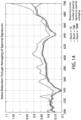
- the software control module receives a signal based upon the interference fringes created by the fringe generating optics which corresponds to a plurality of interferograms within the single image. For each single raw interferogram a Fourier transform is performed to obtain a single spectral signature, and then the process is repeated. The single spectral signatures are averaged together to produce an average spectral signature of the object. It has been found that this average spectral signature derived empirically of known references correlates well with the actual spectral signature of such known references.
- Fig. 14 demonstrates examples of this averaging technique. Three different averages are shown. Generally the more signatures are averaged, the greater the noise reduction. A first curve is an average of 10 spectral signatures, showing significant noise. However, when an average of 100 spectral signatures is made the noise is reduced, and when an average of 1000 spectral signatures is made, the noise is reduced even more.
- the simple Fourier transform followed by averaging can be calculated by the processor(s) of the mobile device.
- a processor typically incorporated as part of the mobile device can be used to process a signal generated by the camera corresponding to the raw image of fringes into a processed spectral signature by the use of Fourier transforms and averaging.
- the characteristic wavelengths in the processed spectral signature may be a spectral fingerprint. This spectral fingerprint can be used for matching with reference spectra stored in a mobile device database, or remotely and accessed via a network.
- a useful optical parameter in material analysis is spectral reflectance (or spectral absorbance).
- the spectral signature of the object depends on the spectral reflectance of the object (which is an intrinsic material property) and the spectrum of light illuminating the object.
- the flash light or light source 77 is relatively consistent from phone to phone or device to device.
- the spectral signature of the flash light can be determined by measuring the spectral signature of a reference material with a known calibrated spectral reflectance at a fixed distance from the reference material. Once the spectral signature of the flash light is known, the spectral reflectance of the object can be determined.
- the spectral reflectance of an object is the division of the spectral signature of light reflected by the object with the spectral signature of the flash light.
- the spectral signature of an object varies depending upon the light shone upon the object.
- An object will look different with indoor lighting, outdoor natural lighting, LED, fluorescent lighting, etc.
- the object's spectral reflectance is an intrinsic property of the object while the object's spectral signature depends upon the light falling on the object (and reflected to the spectrometer).
- the compact spectrometer disclosed herein allows for its use for precise and tailored colour measurements, which can be useful as a sales and marketing tool by vendors to potential customers (which would be understood as including a broad range of people, including the vendor or vendor's agents and customers) who are particular about the colour of an item in different lighting conditions.
- a vendor of an item that offers a wide range of colours, such as clothing, for example can offer a customer the spectral reflectance of the item and the option of viewing this item under a wide range of different light sources.
- the steps involved are based on the relationship between spectral signature and spectral reflectance, and comprise calibrating the spectral signature of the standard light source (used as the standard, as could be found for display of the item on a website, for example) or using the calibrated spectral signature of the flash light, measuring the item's spectral reflectance, and making the item's spectral reflectance available to potential customers.
- the potential customer uses this information of the spectral reflectance of the item, and the spectral signature of a light source or a particular lighting condition of interest, to determine a simulated spectral signature of the item. In this manner the potential customer can see how the item will look in a variety of different lighting conditions.
- the spectral signature of the light source is calibrated. If the flash light is exactly the same from device to device, then a factory calibration is sufficient. However, the actual spectral signature of the flash light may deviate a bit and may degrade over time, so a reference material may be used to measure the actual spectral signature of the flash light.
- the vendor may use the same technique to calibrate an alternate light source/lighting condition of interest.
- the vendor measures the item's spectral reflectance. Then the vendor (which is understood here to mean the vendor or the vendor's agent) makes the item's calibrated spectral reflectance available to potential customers.
- the method for making colour measurements of the item described above is dramatically simplified with the use of the compact spectrometers disclosed herein.
- the vendor uses the spectrometer during the step of measuring the spectral reflectance of the item.
- the vendor may also optionally use the spectrometer during the first step of obtaining a spectral signature of a standard light source.
- the customer or potential customer would use a spectrometer during the step of determining a simulated spectral signature of the item.
- the spectrometer used by the customer may be the same or different than the spectrometer used by the vendor.
Landscapes
- Physics & Mathematics (AREA)
- Spectroscopy & Molecular Physics (AREA)
- General Physics & Mathematics (AREA)
- Optics & Photonics (AREA)
- Spectrometry And Color Measurement (AREA)
- Polarising Elements (AREA)
- Investigating Or Analysing Materials By Optical Means (AREA)
Claims (11)
- Spectromètre optique (10) destiné à mesurer une signature spectrale d'un objet comprenant, en combinaison :une optique génératrice de franges (12) ;une caméra numérique (65) adaptée pour recevoir les franges d'interférence ; etun processeur adapté pour générer la signature spectrale de l'objet ;dans lequel l'optique génératrice de franges (12) crée des franges d'interférence à partir de la lumière d'un objet et qui est adaptée pour transmettre les franges d'interférence à la caméra, qui génère un signal qui est à son tour relayé au processeur pour générer la signature spectrale de l'objet,l'optique génératrice de franges (12) comprenant, en combinaison :une optique avant (45) comprenantun diffuseur (40) adapté pour recevoir et diffuser la lumière de l'objet ; etune optique biréfringente (55), adaptée pour recevoir la lumière diffuse du diffuseur, caractérisé en ce que l'optique biréfringente comprendun premier polariseur (20) ;une première plaque biréfringente plate (22) ;une seconde plaque biréfringente plate (24) parallèle à la première plaque biréfringente plate (22) ; etun second polariseur (26), dans lequel le diffuseur (40) est formé sur ou de manière immédiatement adjacente au premier polariseur (20), la lumière diffusée se propage du diffuseur (40) au premier polariseur (20), puis à la première plaque biréfringente plate parallèle (22), puis à la seconde plaque biréfringente plate parallèle (24) puis au second polariseur (26) ;dans lequel le premier polariseur (20) et le second polariseur (26) sont chacun adaptés pour transmettre la lumière polarisée linéairement à un angle de polarisation formé dans un plan perpendiculaire à une direction de transmission de la lumière à travers l'optique biréfringente (55).
- Spectromètre optique (10) selon la revendication 1, dans lequel la caméra est adaptée pour générer un signal correspondant aux franges d'interférence reçues créées par l'optique génératrice de franges (12) qui correspond à une pluralité d'interférogrammes dans une seule image ; et
le processeur est adapté pour calculer la signature spectrale de l'objet en effectuant une transformée de Fourier de chacun de la pluralité d'interférogrammes et en prenant une moyenne des transformées de Fourier des interférogrammes. - Spectromètre optique (10) selon la revendication 1 ou 2, dans lequel le diffuseur (40) comprend soit :une couche séparée de l'optique biréfringente ayant une surface optique meulée rugueuse ;une surface avant meulée rugueuse d'un premier polariseur de l'optique biréfringente ; ouun réseau lenticulaire à microlentilles.
- Dispositif mobile comprenant la caméra numérique et le spectromètre optique (10) selon l'une quelconque des revendications 2 à 3 et comprenant en outreun boîtier (80) pour l'optique avant et l'optique biréfringente, dans lequel le boîtier (80) est formé comme une fixation externe adaptée pour être placée sur le dispositif mobile (90) ;dans lequel le boîtier (80) est soit fixe, soit réglable entre une position opérationnelle où l'optique biréfringente est positionnée devant la caméra, et une position non opérationnelle où l'optique biréfringentes n'est pas positionnée devant la caméra.
- Dispositif mobile selon la revendication 4, comprenant en outre un diffuseur de lumière (75) adapté pour diffuser la lumière à partir d'une source lumineuse.
- Spectromètre optique (10) selon l'une quelconque des revendications 2 à 3, dans lequel l'optique avant comprend en outre une lentille (44) et un masque (42) définissant une ouverture (43) ;
dans lequel la lumière provenant de l'objet passe à travers la lentille, puis à travers l'ouverture, puis à travers le diffuseur, puis à travers l'optique biréfringente. - Spectromètre optique (10) selon la revendication 1, dans lequel la première plaque biréfringente a un premier axe optique à un premier angle formé dans un plan X-Z formé par un axe X et un axe Z, dans lequel l'axe Z est la direction de transmission de la lumière à travers l'optique biréfringente.
- Spectromètre optique (10) selon la revendication 7, dans lequel la seconde plaque biréfringente a un second axe optique dans un plan perpendiculaire à l'axe z.
- Spectromètre optique (10) selon la revendication 7, dans lequel la seconde plaque biréfringente a une biréfringence opposée à une biréfringence de la première plaque biréfringente, et un second axe optique à un second angle formé dans le plan X-Z.
- Spectromètre optique (10) selon la revendication 1, dans lequel la première plaque biréfringente a une première épaisseur (25), la seconde plaque biréfringente a une seconde épaisseur (27) et la seconde épaisseur est différente de la première épaisseur.
- Spectromètre optique (10) selon la revendication 1, dans lequel la première plaque biréfringente a une première épaisseur, la seconde plaque biréfringente a une seconde épaisseur, et la seconde épaisseur est la même que la première épaisseur ; et
une plaque à demi-onde (50) est positionnée entre la première plaque biréfringente et la seconde plaque biréfringente.
Applications Claiming Priority (1)
| Application Number | Priority Date | Filing Date | Title |
|---|---|---|---|
| SG10201501196PA SG10201501196PA (en) | 2015-02-16 | 2015-02-16 | Compact spectrometer |
Publications (3)
| Publication Number | Publication Date |
|---|---|
| EP3056880A2 EP3056880A2 (fr) | 2016-08-17 |
| EP3056880A3 EP3056880A3 (fr) | 2016-10-26 |
| EP3056880B1 true EP3056880B1 (fr) | 2023-09-27 |
Family
ID=55699973
Family Applications (1)
| Application Number | Title | Priority Date | Filing Date |
|---|---|---|---|
| EP15175050.2A Active EP3056880B1 (fr) | 2015-02-16 | 2015-07-02 | Spectromètre compact |
Country Status (5)
| Country | Link |
|---|---|
| US (1) | US9316540B1 (fr) |
| EP (1) | EP3056880B1 (fr) |
| JP (1) | JP6516691B2 (fr) |
| CN (1) | CN105890762A (fr) |
| SG (1) | SG10201501196PA (fr) |
Families Citing this family (12)
| Publication number | Priority date | Publication date | Assignee | Title |
|---|---|---|---|---|
| US10113970B2 (en) | 2015-08-20 | 2018-10-30 | National Taiwan University | Detection device |
| DE102015219672A1 (de) | 2015-09-10 | 2017-03-16 | Robert Bosch Gmbh | Miniaturspektrometer und Verfahren zur Ermittlung eines Spektrums der von einem Objekt reflektierten, transmittierten oder emittierten Strahlung |
| US10801963B2 (en) | 2018-08-22 | 2020-10-13 | Paul Bartholomew | Raman spectroscopy for minerals identification |
| DE102018203840A1 (de) * | 2018-03-14 | 2019-09-19 | Robert Bosch Gmbh | Fourier-Transform-Spektrometer, Verfahren zum Herstellen eines Fourier-Transform-Spektrometers und Verfahren zur Darstellung eines elektromagnetischen Spektrums |
| RU2682593C1 (ru) * | 2018-03-30 | 2019-03-19 | Самсунг Электроникс Ко., Лтд. | Ультракомпактный спектрометр высокого разрешения и способ его применения |
| US11330983B2 (en) | 2018-03-30 | 2022-05-17 | Samsung Electronics Co., Ltd. | Electronic device for acquiring state information on object, and control method therefor |
| DE102018208185A1 (de) | 2018-05-24 | 2019-11-28 | Robert Bosch Gmbh | Optisches Element zur Lichtkonzentration und Herstellungsverfahren für ein optisches Element zur Lichtkonzentration |
| KR102091419B1 (ko) * | 2018-07-19 | 2020-03-20 | 주식회사 케이씨텍 | 광투과성 연마층을 갖는 기판 연마 시스템 |
| US11245875B2 (en) * | 2019-01-15 | 2022-02-08 | Microsoft Technology Licensing, Llc | Monitoring activity with depth and multi-spectral camera |
| JP2022545405A (ja) * | 2019-08-16 | 2022-10-27 | バーソロミュー、ポール | 鉱物同定のためのラマン分光法 |
| WO2021117288A1 (fr) * | 2019-12-11 | 2021-06-17 | 日東電工株式会社 | Plaque de polarisation, ensemble de plaques de polarisation et dispositif d'affichage d'image |
| CN114829994A (zh) * | 2019-12-11 | 2022-07-29 | 日东电工株式会社 | 偏振板、偏振板组和图像显示装置 |
Family Cites Families (28)
| Publication number | Priority date | Publication date | Assignee | Title |
|---|---|---|---|---|
| JP3095167B2 (ja) * | 1989-04-11 | 2000-10-03 | 聡 河田 | マルチチャネルフーリエ変換分光装置 |
| GB9314302D0 (en) | 1993-07-10 | 1993-08-25 | Univ Court Of The University O | Improved spectrometer |
| JPH07286902A (ja) * | 1994-04-18 | 1995-10-31 | Yokogawa Electric Corp | フーリエ分光器 |
| GB2305257B (en) | 1995-09-12 | 1999-08-18 | Siemens Plc | Improvements in or relating to spectrometers |
| CN1265738A (zh) * | 1997-07-29 | 2000-09-06 | 威廉·布拉德肖·阿莫斯 | 用于光学成像傅里叶谱仪的光学设备及其操作方法 |
| EP0939323A1 (fr) | 1998-02-28 | 1999-09-01 | C.S.E.M. Centre Suisse D'electronique Et De Microtechnique Sa | Prisme de Wollaston et son utilisation dans un spectromètre à transformée de Fourier |
| US6222632B1 (en) | 1999-04-07 | 2001-04-24 | Luxtron Corporation | Polarization interferometer spectrometer with rotatable birefringent element |
| WO2001002799A1 (fr) | 1999-07-02 | 2001-01-11 | Cambridge Research & Instrumentation Inc. | Interferometre a birefringence |
| EP1306987A1 (fr) | 2001-10-23 | 2003-05-02 | Pro Forma Alfa | Spectromètre |
| JP2004053836A (ja) * | 2002-07-18 | 2004-02-19 | Matsushita Electric Ind Co Ltd | 携帯電話機 |
| US7738095B2 (en) | 2003-07-18 | 2010-06-15 | Chemimage Corporation | Method and apparatus for compact spectrometer for detecting hazardous agents |
| CN100437020C (zh) | 2003-07-18 | 2008-11-26 | 凯米映像公司 | 多波长成像光谱仪的方法和装置 |
| JP4567474B2 (ja) * | 2004-01-27 | 2010-10-20 | 株式会社 液晶先端技術開発センター | 光照射装置、結晶化装置、および結晶化方法 |
| JP4492946B2 (ja) * | 2004-07-08 | 2010-06-30 | 株式会社 液晶先端技術開発センター | 光照射装置、結晶化装置、結晶化方法 |
| JP4635201B2 (ja) * | 2005-05-23 | 2011-02-23 | 国立大学法人 長崎大学 | 端末装置 |
| JP2007292670A (ja) * | 2006-04-27 | 2007-11-08 | Sumitomo Electric Ind Ltd | 干渉計センサおよびそれを用いた光学測定装置 |
| FR2940447B1 (fr) | 2008-12-23 | 2011-10-21 | Continental Automotive France | Spectrometre miniature embarque dans un vehicule automobile a detecteur de mesure et detecteur de reference unique |
| JP5493509B2 (ja) * | 2009-06-30 | 2014-05-14 | 株式会社リコー | 分光装置および分光方法 |
| SG173235A1 (en) | 2010-01-29 | 2011-08-29 | Dso Nat Lab | Hyperspectral imaging device |
| US9046422B2 (en) | 2011-04-20 | 2015-06-02 | The Arizona Board Of Regents On Behalf Of The University Of Arizona | Ultra-compact snapshot imaging fourier transform spectrometer |
| US9076068B2 (en) * | 2010-10-04 | 2015-07-07 | Datacolor Holding Ag | Method and apparatus for evaluating color in an image |
| US8305577B2 (en) * | 2010-11-04 | 2012-11-06 | Nokia Corporation | Method and apparatus for spectrometry |
| US20140022535A1 (en) * | 2011-03-31 | 2014-01-23 | Shinji Yamamoto | Optical Characteristic Measuring Apparatus and Method |
| JP5806504B2 (ja) * | 2011-05-17 | 2015-11-10 | オリンパス株式会社 | 撮像装置およびこれを備える顕微鏡システム |
| JP6082557B2 (ja) * | 2012-09-28 | 2017-02-15 | グローリー株式会社 | スペクトルセンサの光学系調整方法及び光学系調整装置並びに紙葉類識別装置 |
| JP6311267B2 (ja) * | 2013-05-10 | 2018-04-18 | 株式会社リコー | 分光特性取得装置、画像評価装置、画像形成装置 |
| US8830475B1 (en) | 2013-08-19 | 2014-09-09 | National Cheng Kung University | Interferometer and spatial interference fourier transform spectrometer |
| CN103674902A (zh) * | 2013-12-12 | 2014-03-26 | 中国科学院半导体研究所 | 基于手机平台的lspr便携式生化检测仪 |
-
2015
- 2015-02-16 SG SG10201501196PA patent/SG10201501196PA/en unknown
- 2015-03-10 US US14/642,827 patent/US9316540B1/en active Active
- 2015-07-02 EP EP15175050.2A patent/EP3056880B1/fr active Active
-
2016
- 2016-02-08 JP JP2016022243A patent/JP6516691B2/ja active Active
- 2016-02-16 CN CN201610087856.6A patent/CN105890762A/zh active Pending
Also Published As
| Publication number | Publication date |
|---|---|
| EP3056880A3 (fr) | 2016-10-26 |
| US9316540B1 (en) | 2016-04-19 |
| JP2016183957A (ja) | 2016-10-20 |
| CN105890762A (zh) | 2016-08-24 |
| EP3056880A2 (fr) | 2016-08-17 |
| JP6516691B2 (ja) | 2019-05-22 |
| SG10201501196PA (en) | 2016-09-29 |
Similar Documents
| Publication | Publication Date | Title |
|---|---|---|
| US9316539B1 (en) | Compact spectrometer | |
| EP3056880B1 (fr) | Spectromètre compact | |
| US8368889B2 (en) | Compact snapshot polarimetry camera | |
| EP3371548B1 (fr) | Imagerie polarimétrique en 3d à l'aide d'un modèle de diffusion à microfacettes pour compenser des réflexions de scène structurées | |
| Zhang et al. | High throughput static channeled interference imaging spectropolarimeter based on a Savart polariscope | |
| US8797532B2 (en) | System and method for polarization measurement | |
| WO2011093794A1 (fr) | Dispositif de radiométrie spectrale imageante | |
| US20180321083A1 (en) | Miniature Spectrometer and a Spectroscopic Method | |
| US20050007591A1 (en) | Instantaneous polarization measurement system and method | |
| Scheeline | Smartphone technology–instrumentation and applications | |
| Hagen et al. | Generating high-performance polarization measurements with low-performance polarizers: demonstration with a microgrid polarization camera | |
| US6373569B1 (en) | Method and device for the spectral analysis of light | |
| KR20180000879A (ko) | 직선편광으로 인한 계측오차가 보정된 휘도색도계 | |
| CN107314839A (zh) | 基于穆勒矩阵的应力检测装置及方法 | |
| Kudenov et al. | Fieldable Mueller matrix imaging spectropolarimeter using a hybrid spatial and temporal modulation scheme | |
| Sassolas et al. | High precision metrology for large bandpass filters | |
| US6646743B2 (en) | Method and device for the spectral analysis of light | |
| Dereniak | From the outside looking in: developing snapshot imaging spectro-polarimeters | |
| Perri et al. | A hyperspectral camera for conservation science, based on a birefringent ultrastable common path interferometer | |
| Li et al. | Experimental research for relative radiometric calibration of imaging spectrometer based on Savart plates | |
| Haefner et al. | Post-optic MTF measurement using a reference optic | |
| Matchko et al. | Polarization measurements using a commercial off-the-shelf digital camera | |
| Richter et al. | Specifying polarimetric tolerances of a high-resolution imaging multiple-species atmospheric profiler (HiMAP) | |
| US11215504B2 (en) | High-throughput compact static-Fourier-transform spectrometer | |
| Němcová et al. | Compensating for colour artefacts in the design of technical kaleidoscopes |
Legal Events
| Date | Code | Title | Description |
|---|---|---|---|
| PUAI | Public reference made under article 153(3) epc to a published international application that has entered the european phase |
Free format text: ORIGINAL CODE: 0009012 |
|
| AK | Designated contracting states |
Kind code of ref document: A2 Designated state(s): AL AT BE BG CH CY CZ DE DK EE ES FI FR GB GR HR HU IE IS IT LI LT LU LV MC MK MT NL NO PL PT RO RS SE SI SK SM TR |
|
| AX | Request for extension of the european patent |
Extension state: BA ME |
|
| PUAL | Search report despatched |
Free format text: ORIGINAL CODE: 0009013 |
|
| AK | Designated contracting states |
Kind code of ref document: A3 Designated state(s): AL AT BE BG CH CY CZ DE DK EE ES FI FR GB GR HR HU IE IS IT LI LT LU LV MC MK MT NL NO PL PT RO RS SE SI SK SM TR |
|
| AX | Request for extension of the european patent |
Extension state: BA ME |
|
| RIC1 | Information provided on ipc code assigned before grant |
Ipc: G01J 3/453 20060101ALI20160921BHEP Ipc: G01J 3/02 20060101AFI20160921BHEP |
|
| STAA | Information on the status of an ep patent application or granted ep patent |
Free format text: STATUS: REQUEST FOR EXAMINATION WAS MADE |
|
| 17P | Request for examination filed |
Effective date: 20170131 |
|
| RBV | Designated contracting states (corrected) |
Designated state(s): AL AT BE BG CH CY CZ DE DK EE ES FI FR GB GR HR HU IE IS IT LI LT LU LV MC MK MT NL NO PL PT RO RS SE SI SK SM TR |
|
| STAA | Information on the status of an ep patent application or granted ep patent |
Free format text: STATUS: EXAMINATION IS IN PROGRESS |
|
| 17Q | First examination report despatched |
Effective date: 20170504 |
|
| STAA | Information on the status of an ep patent application or granted ep patent |
Free format text: STATUS: EXAMINATION IS IN PROGRESS |
|
| STAA | Information on the status of an ep patent application or granted ep patent |
Free format text: STATUS: EXAMINATION IS IN PROGRESS |
|
| RIC1 | Information provided on ipc code assigned before grant |
Ipc: G01J 3/447 20060101ALI20230228BHEP Ipc: G01J 3/453 20060101ALI20230228BHEP Ipc: G01J 3/02 20060101AFI20230228BHEP |
|
| GRAP | Despatch of communication of intention to grant a patent |
Free format text: ORIGINAL CODE: EPIDOSNIGR1 |
|
| STAA | Information on the status of an ep patent application or granted ep patent |
Free format text: STATUS: GRANT OF PATENT IS INTENDED |
|
| INTG | Intention to grant announced |
Effective date: 20230412 |
|
| GRAS | Grant fee paid |
Free format text: ORIGINAL CODE: EPIDOSNIGR3 |
|
| GRAA | (expected) grant |
Free format text: ORIGINAL CODE: 0009210 |
|
| STAA | Information on the status of an ep patent application or granted ep patent |
Free format text: STATUS: THE PATENT HAS BEEN GRANTED |
|
| AK | Designated contracting states |
Kind code of ref document: B1 Designated state(s): AL AT BE BG CH CY CZ DE DK EE ES FI FR GB GR HR HU IE IS IT LI LT LU LV MC MK MT NL NO PL PT RO RS SE SI SK SM TR |
|
| REG | Reference to a national code |
Ref country code: GB Ref legal event code: FG4D |
|
| REG | Reference to a national code |
Ref country code: CH Ref legal event code: EP |
|
| REG | Reference to a national code |
Ref country code: DE Ref legal event code: R096 Ref document number: 602015085826 Country of ref document: DE |
|
| REG | Reference to a national code |
Ref country code: IE Ref legal event code: FG4D |
|
| REG | Reference to a national code |
Ref country code: LT Ref legal event code: MG9D |
|
| PG25 | Lapsed in a contracting state [announced via postgrant information from national office to epo] |
Ref country code: GR Free format text: LAPSE BECAUSE OF FAILURE TO SUBMIT A TRANSLATION OF THE DESCRIPTION OR TO PAY THE FEE WITHIN THE PRESCRIBED TIME-LIMIT Effective date: 20231228 |
|
| PG25 | Lapsed in a contracting state [announced via postgrant information from national office to epo] |
Ref country code: SE Free format text: LAPSE BECAUSE OF FAILURE TO SUBMIT A TRANSLATION OF THE DESCRIPTION OR TO PAY THE FEE WITHIN THE PRESCRIBED TIME-LIMIT Effective date: 20230927 Ref country code: RS Free format text: LAPSE BECAUSE OF FAILURE TO SUBMIT A TRANSLATION OF THE DESCRIPTION OR TO PAY THE FEE WITHIN THE PRESCRIBED TIME-LIMIT Effective date: 20230927 Ref country code: NO Free format text: LAPSE BECAUSE OF FAILURE TO SUBMIT A TRANSLATION OF THE DESCRIPTION OR TO PAY THE FEE WITHIN THE PRESCRIBED TIME-LIMIT Effective date: 20231227 Ref country code: LV Free format text: LAPSE BECAUSE OF FAILURE TO SUBMIT A TRANSLATION OF THE DESCRIPTION OR TO PAY THE FEE WITHIN THE PRESCRIBED TIME-LIMIT Effective date: 20230927 Ref country code: LT Free format text: LAPSE BECAUSE OF FAILURE TO SUBMIT A TRANSLATION OF THE DESCRIPTION OR TO PAY THE FEE WITHIN THE PRESCRIBED TIME-LIMIT Effective date: 20230927 Ref country code: GR Free format text: LAPSE BECAUSE OF FAILURE TO SUBMIT A TRANSLATION OF THE DESCRIPTION OR TO PAY THE FEE WITHIN THE PRESCRIBED TIME-LIMIT Effective date: 20231228 Ref country code: FI Free format text: LAPSE BECAUSE OF FAILURE TO SUBMIT A TRANSLATION OF THE DESCRIPTION OR TO PAY THE FEE WITHIN THE PRESCRIBED TIME-LIMIT Effective date: 20230927 |
|
| REG | Reference to a national code |
Ref country code: NL Ref legal event code: MP Effective date: 20230927 |
|
| REG | Reference to a national code |
Ref country code: AT Ref legal event code: MK05 Ref document number: 1615829 Country of ref document: AT Kind code of ref document: T Effective date: 20230927 |
|
| PG25 | Lapsed in a contracting state [announced via postgrant information from national office to epo] |
Ref country code: NL Free format text: LAPSE BECAUSE OF FAILURE TO SUBMIT A TRANSLATION OF THE DESCRIPTION OR TO PAY THE FEE WITHIN THE PRESCRIBED TIME-LIMIT Effective date: 20230927 |
|
| PG25 | Lapsed in a contracting state [announced via postgrant information from national office to epo] |
Ref country code: IS Free format text: LAPSE BECAUSE OF FAILURE TO SUBMIT A TRANSLATION OF THE DESCRIPTION OR TO PAY THE FEE WITHIN THE PRESCRIBED TIME-LIMIT Effective date: 20240127 |
|
| PG25 | Lapsed in a contracting state [announced via postgrant information from national office to epo] |
Ref country code: AT Free format text: LAPSE BECAUSE OF FAILURE TO SUBMIT A TRANSLATION OF THE DESCRIPTION OR TO PAY THE FEE WITHIN THE PRESCRIBED TIME-LIMIT Effective date: 20230927 |
|
| PG25 | Lapsed in a contracting state [announced via postgrant information from national office to epo] |
Ref country code: ES Free format text: LAPSE BECAUSE OF FAILURE TO SUBMIT A TRANSLATION OF THE DESCRIPTION OR TO PAY THE FEE WITHIN THE PRESCRIBED TIME-LIMIT Effective date: 20230927 |
|
| PG25 | Lapsed in a contracting state [announced via postgrant information from national office to epo] |
Ref country code: SM Free format text: LAPSE BECAUSE OF FAILURE TO SUBMIT A TRANSLATION OF THE DESCRIPTION OR TO PAY THE FEE WITHIN THE PRESCRIBED TIME-LIMIT Effective date: 20230927 Ref country code: RO Free format text: LAPSE BECAUSE OF FAILURE TO SUBMIT A TRANSLATION OF THE DESCRIPTION OR TO PAY THE FEE WITHIN THE PRESCRIBED TIME-LIMIT Effective date: 20230927 Ref country code: IS Free format text: LAPSE BECAUSE OF FAILURE TO SUBMIT A TRANSLATION OF THE DESCRIPTION OR TO PAY THE FEE WITHIN THE PRESCRIBED TIME-LIMIT Effective date: 20240127 Ref country code: ES Free format text: LAPSE BECAUSE OF FAILURE TO SUBMIT A TRANSLATION OF THE DESCRIPTION OR TO PAY THE FEE WITHIN THE PRESCRIBED TIME-LIMIT Effective date: 20230927 Ref country code: EE Free format text: LAPSE BECAUSE OF FAILURE TO SUBMIT A TRANSLATION OF THE DESCRIPTION OR TO PAY THE FEE WITHIN THE PRESCRIBED TIME-LIMIT Effective date: 20230927 Ref country code: CZ Free format text: LAPSE BECAUSE OF FAILURE TO SUBMIT A TRANSLATION OF THE DESCRIPTION OR TO PAY THE FEE WITHIN THE PRESCRIBED TIME-LIMIT Effective date: 20230927 Ref country code: AT Free format text: LAPSE BECAUSE OF FAILURE TO SUBMIT A TRANSLATION OF THE DESCRIPTION OR TO PAY THE FEE WITHIN THE PRESCRIBED TIME-LIMIT Effective date: 20230927 Ref country code: SK Free format text: LAPSE BECAUSE OF FAILURE TO SUBMIT A TRANSLATION OF THE DESCRIPTION OR TO PAY THE FEE WITHIN THE PRESCRIBED TIME-LIMIT Effective date: 20230927 Ref country code: PT Free format text: LAPSE BECAUSE OF FAILURE TO SUBMIT A TRANSLATION OF THE DESCRIPTION OR TO PAY THE FEE WITHIN THE PRESCRIBED TIME-LIMIT Effective date: 20240129 |