EP3056366A1 - Vehicle exterior design member and vehicle back door - Google Patents
Vehicle exterior design member and vehicle back door Download PDFInfo
- Publication number
- EP3056366A1 EP3056366A1 EP16154685.8A EP16154685A EP3056366A1 EP 3056366 A1 EP3056366 A1 EP 3056366A1 EP 16154685 A EP16154685 A EP 16154685A EP 3056366 A1 EP3056366 A1 EP 3056366A1
- Authority
- EP
- European Patent Office
- Prior art keywords
- edge portion
- outer edge
- panel
- inner panel
- vehicle
- Prior art date
- Legal status (The legal status is an assumption and is not a legal conclusion. Google has not performed a legal analysis and makes no representation as to the accuracy of the status listed.)
- Granted
Links
- 239000011347 resin Substances 0.000 claims description 56
- 229920005989 resin Polymers 0.000 claims description 56
- 230000003014 reinforcing effect Effects 0.000 claims description 24
- 230000003313 weakening effect Effects 0.000 claims description 4
- 239000004918 carbon fiber reinforced polymer Substances 0.000 abstract description 17
- 239000004743 Polypropylene Substances 0.000 abstract description 8
- -1 polypropylene Polymers 0.000 abstract description 8
- 229920001155 polypropylene Polymers 0.000 abstract description 8
- 239000011521 glass Substances 0.000 description 25
- 239000000853 adhesive Substances 0.000 description 8
- 230000001070 adhesive effect Effects 0.000 description 8
- 230000002787 reinforcement Effects 0.000 description 7
- 230000006641 stabilisation Effects 0.000 description 7
- 238000011105 stabilization Methods 0.000 description 7
- 239000012141 concentrate Substances 0.000 description 5
- 230000002093 peripheral effect Effects 0.000 description 5
- 230000000694 effects Effects 0.000 description 4
- 238000004519 manufacturing process Methods 0.000 description 4
- 239000002131 composite material Substances 0.000 description 3
- 239000002184 metal Substances 0.000 description 3
- 238000000034 method Methods 0.000 description 3
- 238000005336 cracking Methods 0.000 description 2
- 239000000835 fiber Substances 0.000 description 2
- 239000002657 fibrous material Substances 0.000 description 2
- 239000005357 flat glass Substances 0.000 description 2
- 230000000153 supplemental effect Effects 0.000 description 2
- 229920000049 Carbon (fiber) Polymers 0.000 description 1
- 239000011230 binding agent Substances 0.000 description 1
- 239000004917 carbon fiber Substances 0.000 description 1
- 230000000994 depressogenic effect Effects 0.000 description 1
- 238000005304 joining Methods 0.000 description 1
- 238000012986 modification Methods 0.000 description 1
- 230000004048 modification Effects 0.000 description 1
- 239000004033 plastic Substances 0.000 description 1
- 229920003023 plastic Polymers 0.000 description 1
- 230000000087 stabilizing effect Effects 0.000 description 1
- XLYOFNOQVPJJNP-UHFFFAOYSA-N water Substances O XLYOFNOQVPJJNP-UHFFFAOYSA-N 0.000 description 1
- 239000013585 weight reducing agent Substances 0.000 description 1
Images


Classifications
-
- B—PERFORMING OPERATIONS; TRANSPORTING
- B60—VEHICLES IN GENERAL
- B60J—WINDOWS, WINDSCREENS, NON-FIXED ROOFS, DOORS, OR SIMILAR DEVICES FOR VEHICLES; REMOVABLE EXTERNAL PROTECTIVE COVERINGS SPECIALLY ADAPTED FOR VEHICLES
- B60J5/00—Doors
- B60J5/10—Doors arranged at the vehicle rear
- B60J5/101—Doors arranged at the vehicle rear for non-load transporting vehicles, i.e. family cars including vans
- B60J5/107—Doors arranged at the vehicle rear for non-load transporting vehicles, i.e. family cars including vans constructional details, e.g. about door frame, panels, materials used, reinforcements
-
- B—PERFORMING OPERATIONS; TRANSPORTING
- B60—VEHICLES IN GENERAL
- B60J—WINDOWS, WINDSCREENS, NON-FIXED ROOFS, DOORS, OR SIMILAR DEVICES FOR VEHICLES; REMOVABLE EXTERNAL PROTECTIVE COVERINGS SPECIALLY ADAPTED FOR VEHICLES
- B60J5/00—Doors
- B60J5/10—Doors arranged at the vehicle rear
-
- B—PERFORMING OPERATIONS; TRANSPORTING
- B32—LAYERED PRODUCTS
- B32B—LAYERED PRODUCTS, i.e. PRODUCTS BUILT-UP OF STRATA OF FLAT OR NON-FLAT, e.g. CELLULAR OR HONEYCOMB, FORM
- B32B27/00—Layered products comprising a layer of synthetic resin
- B32B27/06—Layered products comprising a layer of synthetic resin as the main or only constituent of a layer, which is next to another layer of the same or of a different material
- B32B27/08—Layered products comprising a layer of synthetic resin as the main or only constituent of a layer, which is next to another layer of the same or of a different material of synthetic resin
-
- B—PERFORMING OPERATIONS; TRANSPORTING
- B32—LAYERED PRODUCTS
- B32B—LAYERED PRODUCTS, i.e. PRODUCTS BUILT-UP OF STRATA OF FLAT OR NON-FLAT, e.g. CELLULAR OR HONEYCOMB, FORM
- B32B3/00—Layered products comprising a layer with external or internal discontinuities or unevennesses, or a layer of non-planar form; Layered products having particular features of form
- B32B3/02—Layered products comprising a layer with external or internal discontinuities or unevennesses, or a layer of non-planar form; Layered products having particular features of form characterised by features of form at particular places, e.g. in edge regions
- B32B3/08—Layered products comprising a layer with external or internal discontinuities or unevennesses, or a layer of non-planar form; Layered products having particular features of form characterised by features of form at particular places, e.g. in edge regions characterised by added members at particular parts
-
- B—PERFORMING OPERATIONS; TRANSPORTING
- B32—LAYERED PRODUCTS
- B32B—LAYERED PRODUCTS, i.e. PRODUCTS BUILT-UP OF STRATA OF FLAT OR NON-FLAT, e.g. CELLULAR OR HONEYCOMB, FORM
- B32B3/00—Layered products comprising a layer with external or internal discontinuities or unevennesses, or a layer of non-planar form; Layered products having particular features of form
- B32B3/26—Layered products comprising a layer with external or internal discontinuities or unevennesses, or a layer of non-planar form; Layered products having particular features of form characterised by a particular shape of the outline of the cross-section of a continuous layer; characterised by a layer with cavities or internal voids ; characterised by an apertured layer
- B32B3/266—Layered products comprising a layer with external or internal discontinuities or unevennesses, or a layer of non-planar form; Layered products having particular features of form characterised by a particular shape of the outline of the cross-section of a continuous layer; characterised by a layer with cavities or internal voids ; characterised by an apertured layer characterised by an apertured layer, the apertures going through the whole thickness of the layer, e.g. expanded metal, perforated layer, slit layer regular cells B32B3/12
-
- B—PERFORMING OPERATIONS; TRANSPORTING
- B60—VEHICLES IN GENERAL
- B60J—WINDOWS, WINDSCREENS, NON-FIXED ROOFS, DOORS, OR SIMILAR DEVICES FOR VEHICLES; REMOVABLE EXTERNAL PROTECTIVE COVERINGS SPECIALLY ADAPTED FOR VEHICLES
- B60J1/00—Windows; Windscreens; Accessories therefor
- B60J1/18—Windows; Windscreens; Accessories therefor arranged at the vehicle rear
-
- B—PERFORMING OPERATIONS; TRANSPORTING
- B60—VEHICLES IN GENERAL
- B60J—WINDOWS, WINDSCREENS, NON-FIXED ROOFS, DOORS, OR SIMILAR DEVICES FOR VEHICLES; REMOVABLE EXTERNAL PROTECTIVE COVERINGS SPECIALLY ADAPTED FOR VEHICLES
- B60J5/00—Doors
- B60J5/04—Doors arranged at the vehicle sides
- B60J5/042—Reinforcement elements
- B60J5/0456—Behaviour during impact
- B60J5/0461—Behaviour during impact characterised by a pre-defined mode of deformation or displacement in order to absorb impact
-
- B—PERFORMING OPERATIONS; TRANSPORTING
- B62—LAND VEHICLES FOR TRAVELLING OTHERWISE THAN ON RAILS
- B62D—MOTOR VEHICLES; TRAILERS
- B62D23/00—Combined superstructure and frame, i.e. monocoque constructions
-
- B—PERFORMING OPERATIONS; TRANSPORTING
- B62—LAND VEHICLES FOR TRAVELLING OTHERWISE THAN ON RAILS
- B62D—MOTOR VEHICLES; TRAILERS
- B62D25/00—Superstructure or monocoque structure sub-units; Parts or details thereof not otherwise provided for
-
- B—PERFORMING OPERATIONS; TRANSPORTING
- B62—LAND VEHICLES FOR TRAVELLING OTHERWISE THAN ON RAILS
- B62D—MOTOR VEHICLES; TRAILERS
- B62D25/00—Superstructure or monocoque structure sub-units; Parts or details thereof not otherwise provided for
- B62D25/08—Front or rear portions
-
- B—PERFORMING OPERATIONS; TRANSPORTING
- B62—LAND VEHICLES FOR TRAVELLING OTHERWISE THAN ON RAILS
- B62D—MOTOR VEHICLES; TRAILERS
- B62D29/00—Superstructures, understructures, or sub-units thereof, characterised by the material thereof
- B62D29/04—Superstructures, understructures, or sub-units thereof, characterised by the material thereof predominantly of synthetic material
- B62D29/043—Superstructures
-
- B—PERFORMING OPERATIONS; TRANSPORTING
- B32—LAYERED PRODUCTS
- B32B—LAYERED PRODUCTS, i.e. PRODUCTS BUILT-UP OF STRATA OF FLAT OR NON-FLAT, e.g. CELLULAR OR HONEYCOMB, FORM
- B32B2605/00—Vehicles
- B32B2605/08—Cars
-
- B—PERFORMING OPERATIONS; TRANSPORTING
- B60—VEHICLES IN GENERAL
- B60J—WINDOWS, WINDSCREENS, NON-FIXED ROOFS, DOORS, OR SIMILAR DEVICES FOR VEHICLES; REMOVABLE EXTERNAL PROTECTIVE COVERINGS SPECIALLY ADAPTED FOR VEHICLES
- B60J5/00—Doors
- B60J5/04—Doors arranged at the vehicle sides
- B60J5/042—Reinforcement elements
- B60J5/0422—Elongated type elements, e.g. beams, cables, belts or wires
- B60J5/0423—Elongated type elements, e.g. beams, cables, belts or wires characterised by position in the lower door structure
- B60J5/0431—Elongated type elements, e.g. beams, cables, belts or wires characterised by position in the lower door structure the elements being arranged at the hinge area
-
- B—PERFORMING OPERATIONS; TRANSPORTING
- B60—VEHICLES IN GENERAL
- B60J—WINDOWS, WINDSCREENS, NON-FIXED ROOFS, DOORS, OR SIMILAR DEVICES FOR VEHICLES; REMOVABLE EXTERNAL PROTECTIVE COVERINGS SPECIALLY ADAPTED FOR VEHICLES
- B60J5/00—Doors
- B60J5/04—Doors arranged at the vehicle sides
- B60J5/042—Reinforcement elements
- B60J5/0422—Elongated type elements, e.g. beams, cables, belts or wires
- B60J5/0423—Elongated type elements, e.g. beams, cables, belts or wires characterised by position in the lower door structure
- B60J5/0433—Elongated type elements, e.g. beams, cables, belts or wires characterised by position in the lower door structure the elements being arranged at the lock area
Definitions
- the invention relates to a vehicle exterior design member in which an inner panel and an outer panel are made of resin.
- Japanese Patent Application Publication JP 2007-313919 A describes a resin panel that is used as an exterior design member and an interior design member of a vehicle.
- This resin panel is a molded article of fiber mat in which fiber material and binder resin are mixed together.
- a weak portion having a weaker fracture strength than other portions in the surface direction is provided by making the composite material of the fiber material different in one part. As a result, the fracture mode (deformation mode) of the resin panel when a collision occurs, for example, is stabilized.
- the composite material must be made different in one part, so manufacturing is complex.
- the exterior design member for a vehicle is formed by joining together a plurality of panels formed in predetermined shapes, so the member formed by the plurality of panels being joined together needs to have a stabilized deformation mode.
- the invention thus provides a vehicle exterior design member and a vehicle back door that contributes to the stabilization of the deformation mode, in a structure in which an inner panel made of resin and an outer panel made of resin are joined together.
- a first aspect of the invention relates to a vehicle exterior design member, comprising: an inner panel made of resin (e.g. CFRP (carbon-fiber-reinforced plastic)); an outer panel made of resin (e.g. polypropylene) that is joined to the inner panel; at least one of the inner panel and the outer panel having an opening or weak portion; a first outer edge portion that is reinforced by a reinforcing member (also made of e.g. CFRP) and forms a portion of an outer edge portion; and a second outer edge portion that has a lower strength than the first outer edge portion and forms another portion of the outer edge portion.
- the opening or the weak portion is arranged adjacent to a boundary portion between the first outer edge portion and the second outer edge portion.
- an opening or weak portion is formed in or on at least one of the panels of a vehicle exterior design member in which an inner panel made of resin and an outer panel made of resin are joined together.
- a portion of the outer edge portion of this vehicle exterior design member is a first outer edge portion
- another portion of the outer edge portion of the vehicle exterior design member is a second outer edge portion.
- the first outer edge portion is reinforced by a reinforcing member, and has a higher strength than the second outer edge portion.
- the boundary portion between the first outer edge portion and the second outer edge portion is arranged adjacent to the opening or the weak portion. That is, the boundary portion between the first outer edge portion and the second outer edge portion where there is a strength difference is weakened by being adjacent to the opening or the weak portion.
- arranged adjacent means, for example, that the boundary portion and the opening or weak portion are arranged such that when the vehicle exterior design member deforms at or near the boundary portion as described above, this deformation location reaches (extends) to at least the opening or the weak portion.
- the reinforcing member may be an outer edge outer panel made of resin, and the first outer edge portion may include a closed section in which the outer edge outer panel is joined to an outer edge portion of the inner panel.
- the first outer edge portion forms a closed section by the resin outer edge outer panel that is a reinforcing member being joined to the outer edge portion of the resin inner panel.
- An open sectional portion having an open sectional shape may be formed on the outer edge portion of the inner panel, and the closed section may be formed by the outer edge outer panel and a portion of the open sectional portion.
- the closed section of the first outer edge portion is formed by the outer edge outer panel, and the portion of the open sectional portion formed on the outer edge portion of the inner panel. Having the open sectional portion formed on the outer edge portion of the inner panel in this way enables the strength of the inner panel to be increased, so the strength of the vehicle exterior design member is able to be ensured mainly by the inner panel. Consequently, the degree of freedom in design of the outer panel is able to be improved.
- open sectional shape refers to, for example, a shape in which a portion of a cross-section is open, such as a hat-shaped sectional shape, a generally U-shaped sectional shape, a generally C-shaped sectional shape, or a generally V-shaped sectional shape.
- the outer panel may be made of resin that has a lower strength than the resin of which the inner panel and the outer edge outer panel are made.
- the outer panel is made of resin that has a lower strength than the resin of which the inner panel and the outer edge outer panel are made, the outer panel has less of an effect on the deformation mode (fracture mode) of the vehicle exterior design member. Therefore, the deformation mode of the vehicle exterior design member is able to be determined mainly by the inner panel and the outer edge outer panel, so the deformation mode of the vehicle exterior design member is able to be easily set (designed).
- the opening may be formed in at least one of the inner panel and the outer panel, and the opening may have another function or use in addition to weakening the boundary portion.
- the opening formed in at least one of the inner panel and the outer panel is arranged adjacent to the boundary portion between the first outer edge portion and the second outer edge portion, so the boundary portion is weakened. Because this opening has a function or use other than weakening the boundary portion as described above (e.g., the opening may also serve as a window hole, a lamp mounting hole, a working hole, a drainage hole, a wiring hole, or a reference hole), it is not necessary to form a special opening or the like to weaken the boundary portion.
- a deformation starting point portion that will be a starting point of deformation of the boundary portion may be formed on the boundary portion.
- the boundary portion can be made to deform with this deformation starting point portion as the starting point, which further contributes to the stabilization of the deformation mode.
- the inner panel may be a door inner panel of a back door of a vehicle
- the outer panel may be a door outer lower panel that is joined to a lower portion of the door inner panel.
- the first outer edge portion may be formed with the reinforcing member connected to an upper edge portion, a left edge portion, and a right edge portion of a first window opening formed in an upper portion of the door inner panel.
- Left and right lower end portions of the first outer edge portion that are positioned farther to a lower end side of the door inner panel than the first window opening may each form a boundary portion between the first outer edge portion and the second outer edge portion.
- the door inner panel of the back door of the vehicle is made of resin.
- a resin door outer lower door panel is joined to the lower portion of this door inner panel, and a first window opening is formed in an upper portion of this door inner panel.
- the reinforcing member is connected to the upper edge portion, the left edge portion, and the right edge portion of this first window opening.
- the first outer edge portion that has a higher strength than the second outer edge portion is formed.
- the left and right lower end portions of this first outer edge portion are both boundary portions between the first outer edge portion and the second outer edge portion.
- the door inner panel tends to deform at or near the left and right boundary portions.
- These left and right boundary portions are positioned farther to the lower portion side of the door inner panel than the first window opening, so the door inner panel is able to be prevented from inadvertently deforming at the left and right edge portions or the like of the window opening.
- a second window opening as the opening may be smaller than the first window opening and be formed extending between left and right lower end portions of the first outer edge portion, in the door inner panel.
- the second window opening is formed between the left and right lower end portions of the first outer edge portion that are positioned farther to the lower end side of the door inner panel than the first window opening, i.e., extending between the left and right boundary portions between the first outer edge portion and the second outer edge portion, in the door inner panel.
- This second window opening improves the rear visibility of the vehicle.
- the left and right boundary portions are weakened by the second window opening that improves the rear visibility of the vehicle in this way, there is no need to form a special opening or the like to weaken the left and right boundary portions.
- a pair of left and right openings may be formed in the outer door panel below the first window opening, and the boundary portions may be arranged adjacent to the left and right openings.
- the pair of left and right openings may be formed in a vertically center portion of the outer panel.
- These openings may be lamp mounting holes for mounting lamps such as tail lamps to the outer panel.
- a dimension in the vehicle width direction of each opening may be set to equal to or greater than 1/10 of a dimension in the vehicle width direction of the outer panel, for example. That is, the total width dimension of the left and right openings may be set to equal to or greater than 1/5 of the width dimension of the outer panel. Accordingly, the outer panel is much weaker at the height where the openings are formed.
- a second aspect of the invention relates to a back door of a vehicle, comprising: a door inner panel made of resin, in which a second window opening that is long in a vehicle width direction, is smaller than a first window opening, and is formed below the first window opening; a door outer lower panel made of resin, which is joined to the door inner panel below the second window opening; and a door outer upper panel that is made of resin and is joined to an upper edge portion, a left edge portion, and a right edge portion of the first window opening in the door inner panel.
- the door outer upper panel and the door inner panel forms a closed sectional structural portion in which left and right end portions of the closed sectional structural portion are arranged adjacent to both outsides in the vehicle width direction of the second window opening.
- the resin door outer upper panel and the door inner panel forms a closed sectional structural portion is joined to the upper edge portion, the left edge portion, and the right edge portion of the first window opening in this door inner panel.
- the left and right lower end portions of this closed sectional structural portion are arranged adjacent to both outsides in the vehicle width direction of the second window opening. That is, the boundary portion (the left and right lower end portions) where the sectional structure changes is weakened by being adjacent to the second window opening.
- the inner panel may be is a side door inner panel of a side door of a vehicle
- the outer panel may be a side door outer panel that is joined to a lower portion of the side door inner panel
- a front first outer edge portion may be formed with a reinforcing member joined to a front edge portion and a front side portion of a lower edge portion of the door inner panel
- a rear first outer edge portion may be formed with a reinforcing member joined to a rear edge portion and a rear side portion of a lower edge portion of the side door inner panel
- the second outer edge portion may be formed between the front and rear first outer edge portions
- the opening may be arranged adjacent to each of a boundary portion between the front first outer edge portion and the second outer edge portion, and a boundary portion between the rear first outer edge portion and the second outer edge portion.
- the inner panel may be a hood inner panel of a hood of a vehicle; the outer panel may be a hood outer lower panel that is joined to an upper side of the hood inner panel; first outer edge portions may be reinforced by a pair of front and rear outer edge outer panels joined to a front portion side of a left edge portion of the hood inner panel and a rear portion side of a left edge portion of the hood inner panel, and by a pair of front and rear outer edge outer panels joined to a front portion side of a right edge portion of the hood inner panel and a rear portion side of the right edge portion of the hood inner panel; second outer edge portions may be positioned between the pair of front and rear outer edge outer panels joined to the left edge portion of the hood inner panel and between the pair of front and rear outer edge outer panels joined to the right edge portion of the hood inner panel; and openings may be positioned near the centers of the second outer edge portions in the vehicle width direction.
- the configuration according to the present invention is also applicable to a hood of a vehicle.
- arranged adjacent means, for example, that the left and right lower end portions and the second window opening are arranged such that when the back door deforms at or near the left and right lower end portions described above, this deformation location reaches (extends) to at least the second window opening.
- the vehicle exterior design member and the vehicle back door according to the invention contribute to the stabilization of the deformation mode, in a structure in which an inner panel made of resin and an outer panel made of resin are joined together.
- arrow FR indicates a forward direction (advancing direction) with respect to a vehicle
- arrow UP indicates an upward direction with respect to the vehicle
- arrow OUT indicates an outside in a vehicle width direction.
- directions of front and rear, left and right, and up and down are used, they will refer to front and rear in a vehicle longitudinal direction, left and right in a vehicle lateral direction (i.e., the vehicle width direction), and up and down in a vehicle vertical direction, respectively.
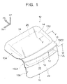
- FIG. 1 is a perspective view of the back door 12 according to the example embodiment viewed diagonally from the rear left.
- This back door 12 is a door that opens and closes a back door opening, not shown, formed in a rear end portion of a vehicle body.
- An upper end portion of the back door 12 is hinge connected to the vehicle body with the vehicle width direction as the axial direction.
- the back door 12 is supported by the vehicle body so as to be able to open and close.
- the back door 12 is formed having a general L-shape when viewed from a side of the vehicle, and includes a door upper portion 12U that extends gently downward at an angle toward the rear of the vehicle from an upper end portion of the back door 12, and a door lower portion 12L that hangs down toward a vehicle lower side from a rear end portion of the door upper portion 12U.
- This back door 12 has a back door main body 10 made of resin (see FIG. 2 ), a back door glass 14 as a window glass, a back door lower glass 16 (hereinafter, simply referred to as "lower glass 16") as a small window glass, and a rear spoiler 18.
- the back door glass 14 is arranged on the door upper portion 12U, and the lower glass 16 is arranged on an upper portion of the door lower portion 12L.
- the rear spoiler 18 is arranged between the back door glass 14 and the lower glass 16.
- the back door glass 14, the lower glass 16, and the rear spoiler 18 are all attached to the back door main body 10.
- FIG. 2 is a perspective view of a back door main body 10 before the lower glass 16 and the rear spoiler 18 are attached to the back door main body.
- This back door main body 10 includes a door inner panel 20 made of resin, a door outer lower panel 22 made of resin that is joined to a lower portion of the door inner panel 20, and a door outer upper panel 24 made of resin that serves as an outer edge outer panel (reinforcing member) that is joined to an upper portion side of the door inner panel 20.
- the door inner panel 20 will be referred to as the "inner panel 20”
- the door outer lower panel 22 will be referred to as the “outer lower panel 22”
- the door outer upper panel 24 will be referred to as the "outer upper panel 24”.
- the inner panel 20 and the outer upper panel 24 are made of CFRP (carbon-fiber-reinforced plastic) in which short carbon fibers are oriented randomly.
- the outer lower panel 22 is made of polypropylene that is a resin having a lower strength than the CFRP described above. This outer lower panel 22 forms an appearance design surface of the vehicle and does not contribute much to the strength and rigidity of the back door main body 10. That is, the strength and rigidity of the back door main body 10 are mainly ensured by the inner panel 20 and the outer upper panel 24.
- FIG. 3 is a perspective view of the inner panel 20 before the outer lower panel 22 is joined thereto
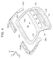
- FIG. 4 is a perspective view of the inner panel 20 before the outer lower panel 22 and the outer upper panel 24 are joined thereto.
- the inner panel 20 is a relatively large panel member that forms the main portion of the back door main body 10.
- An upper portion 20U of this inner panel 20 is arranged on the door upper portion 12U, and a lower portion 20L of the inner panel 20 is arranged on the door lower portion 12L.
- a window opening 26 is formed in the upper portion 20U of the inner panel 20.
- This window opening 26 is formed in a long, generally rectangular shape that is long in the vehicle width direction.
- a small window opening (a window hole) 28 that is more elongated than the window opening 26 is formed long in the vehicle width direction on an upper end side of the lower portion 20L of the inner panel 20, below the window opening 26.
- the window opening 26 and the small window opening 28 are openings for vehicle rear visibility, which are closed (covered) from the vehicle outside by the back door glass 14 and the lower glass 16.
- An outer edge portion of the inner panel 20 is an open sectional portion 21 that has an open sectional shape that is open to the vehicle outside.
- This open sectional portion 21 includes an upper edge component 21A, a lower edge component 21B, a left edge component 21C, and a right edge component 21D that form the upper, lower, left, and right edge portions of the inner panel 20, and is formed along the entire periphery of the outer edge portion of the inner panel 20.
- This open sectional portion 21 improves the strength and rigidity of the inner panel 20.
- the upper edge component 21A forms an upper edge portion of the window opening 26.
- the left edge component 21C and the right edge component 21D form the left and right edge portions, respectively, of the window opening 26 at the upper portion 20U of the inner panel 20, as well as form the left and right edge portions, respectively, of the small window opening 28 at the lower portion 20L of the inner panel 20.
- a center connecting portion 32 that extends in the vehicle width direction is formed near the vertically center portion of the inner panel 20, between the window opening 26 and the small window opening 28.
- the left edge component 21C and the right edge component 21D are integrally connected by this center connecting portion 32.
- the center connecting portion 32 forms a lower edge portion of the window opening 26 and an upper edge portion of the small window opening 28.
- a pair of upper and lower bulging portions 34 and 36 are formed in a vertically middle portion of the lower portion 20L of the inner panel 20.
- These bulging portions 34 and 36 are formed in open sectional shapes that are open on the vehicle inside (vehicle front side) when viewed from the vehicle width direction, and extend in the vehicle width direction below the small window opening 28. These bulging portions 34 and 36 improve the strength and rigidity of the vertically middle portion of the lower portion 20L of the inner panel 20.
- the outer lower panel 22 described above is arranged on the vehicle outside (vehicle rear side) of the lower portion 20L of the inner panel 20.
- This outer lower panel 22 is joined to the inner panel 20 at predetermined locations on the outer edge portion and center side.
- the lower portion 20L of the inner panel 20 is covered from the vehicle outside by this outer lower panel 22.
- this outer lower panel 22 is arranged below the small window opening 28 so that the small window opening 28 is exposed to the vehicle outside.
- An upper protruding portion 22A that protrudes upward is formed on both left and right end portions of the upper edge portion of the outer lower panel 22.
- the outer upper panel 24 described above is arranged on the vehicle outside (on the vehicle rearward inclined upper side) of the upper portion 20U of the inner panel 20.
- the outer upper panel 24 includes a left panel 23 and a right panel 25 that are formed split, as shown in FIG. 4 .
- the left panel 23 and the right panel 25 are formed in general L-shapes and are bilaterally symmetrical, and are joined together by a production adhesive or the like in a state in which the edge portions on the vehicle width direction center side are overlapped with each other.
- the outer upper panel 24 is formed in an overall general U-shape that is open on the vehicle rear side.
- This outer upper panel 24 is overlapped from the vehicle outside with the upper edge component 21A, the upper portion side of the left edge component 21C, and the upper portion side of the right edge component 21D, of the open sectional portion 21 of the inner panel 20. That is, the outer upper panel 24 is arranged on the vehicle upper side and both sides in the vehicle width direction, of the window opening 26.
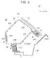
- the back door main body 10 (the back door 12) according to this example embodiment is formed basically bilaterally symmetrical, so only a cross-section on the vehicle right side shown in FIGS. 5 and 6 will be described below. A description of a cross-section on the vehicle left side will be omitted.
- the outer upper panel 24 includes an outer side upper wall portion 24A, an outer side side wall portion 24B, and an outer side inner wall portion 24C.
- the outer side upper wall portion 24A is arranged parallel or substantially parallel to the back door glass 14.
- the outer side side wall portion 24B is bent at a right angle or a substantially right angle in a direction away from the back door glass 14.
- the outer side inner wall portion 24C is bent at an obtuse angle toward the vehicle lower side from an end portion on the extending direction side of the outer side side wall portion 24B.
- the open sectional portion 21 of the inner panel 20 includes an inner side outer wall portion 20A and an inner side bottom wall portion 20B.
- the inner side outer wall portion 20A is arranged farther toward the outside in the vehicle width direction than the outer side side wall portion 24B, and is parallel to the outer side side wall portion 24B.
- the inner side bottom wall portion 20B extends in an L-shape from an end portion on the vehicle lower side of the inner side outer wall portion 20A.
- the inner side outer wall portion 20A extends to the outer side upper wall portion 24A, and then bends toward the outside in the vehicle width direction and becomes an inner side outside flange portion 20C.
- the inner side bottom wall portion 20B extends to the outer side inner wall portion 24C, and then bends toward the vehicle upper side and becomes an inner side inside wall portion 20D.
- a portion of the outer side upper wall portion 24A described above that is on the outer side in the vehicle width direction is an outer side flange portion 24A1.
- a lower surface of this outer side flange portion 24A1 is joined to an upper surface of the inner side outside flange portion 20C by a production adhesive 38.
- an inside surface in the vehicle width direction of the outer side inner wall portion 24C is joined to an outside surface in the vehicle width direction of the inner side inside wall portion 20D by a production adhesive 40.
- the back door glass 14 is joined to an upper surface of the outer side flange portion 24A1 by a peripheral component adhesive 42.
- This peripheral component adhesive 42 is set in a ring shape along the outer edge portion of the back door glass 14.
- a dam member 44 that is a water stopping member (a seal member) is arranged to the outside of the outer periphery of the peripheral component adhesive 42. This dam member 44 is set in a ring shape along the outer edge portion of the back door glass 14.
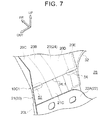
- the outer upper panel 24 described above is provided mainly on the upper portion 20U side of the back door main body 10, as shown in FIGS. 2 and 3 .
- the outer upper panel 24 is not present in the cross-section shown in FIG. 6 (i.e., the cross-section taken along line VI - VI in FIG. 1 ).
- the open sectional portion 21 of the inner panel 20 includes the inner side outer wall portion 20A, the inner side bottom wall portion 20B, the inner side outside flange portion 20C, and the inner side inside wall portion 20D described above.
- an inner side inside flange portion 20E extends toward the center side in the vehicle width direction from a rear end portion of the inner side inside wall portion 20D.
- the lower glass 16 is joined to a rear surface of the inner side outside flange portion 20C by a peripheral component adhesive 46.
- This peripheral component adhesive 46 is set in a ring shape along the outer edge portion of the lower glass 16. As shown in FIGS. 5 and 6 , when the back door 12 is closed, the inner side bottom wall portion 20B is abutted against a weather strip 50 that is attached to a vehicle body 48.
- a portion of the outer edge portion is a first outer edge portion (a high strength outer edge portion) 10A that is reinforced by the outer upper panel 24, and the other portion (the remaining portion) of the outer edge portion is a second outer edge portion (a low strength outer edge portion) 10B that is not reinforced by the outer upper panel 24 (cf. Fig. 1 ).
- the open sectional portion 21 of the inner panel 20 that is made of CFRP and the outer upper panel 24 that is made of CFRP are joined together to form a closed section.
- the strength and rigidity of the first outer edge portion 10A are improved by this closed section.
- This first outer edge portion 10A corresponds to the "closed sectional structural portion" described in the claims.
- the outer upper panel 24 that is made of CFRP is not present, and the strength and rigidity of the second outer edge portion 10B is ensured mainly by the open sectional portion 21 of the inner panel 20. Therefore, the strength and rigidity of the second outer edge portion 10B are set lower than the strength and rigidity of the first outer edge portion 10A.
- the first outer edge portion 10A is arranged on the vehicle upper side and both sides in the vehicle width direction, of the window opening 26, with the left and right lower end portions (rear end portions) being boundary portions 10C1 and 10C2 (10C) between the first outer edge portion 10A and the second outer edge portion 10B.
- These boundary portions 10C1 and 10C2 are positioned farther to the lower end side of the inner panel 20 than the window opening 26.
- the positions of these boundary portions 10C1 and 10C2 match the positions of the left and right lower end portions (rear end portions) 24L1 and 24L2 of the outer upper panel 24.
- the outer upper panel 24 extends farther toward the upper end side of the lower portion 20L than the lower end (rear end) of the upper portion 20U of the inner panel 20, and left and right lower end portions 24L1 and 24L2 are positioned on both sides of the small window opening 28 in the vehicle width direction.
- This small window opening 28 is formed extending between the left and right boundary portions 10C1 and 10C2, and the left and right boundary portions 10C1 and 10C2 are arranged adjacent to, on the outsides in the vehicle width direction of, the small window opening 28.
- the left and right lower end portions 24L1 and 24L2 of the outer upper panel 24 are arranged spaced apart, on the vehicle upper side, from the upper end portions of the left and right upper protruding portions 22A of the outer lower panel 22.
- a pair of left and right recessed portions 52 and 54 that serve as deformation starting point portions are formed on each of the left and right boundary portions 10C1 and 10C2.
- These recessed portions 52 and 54 are formed by part of the inner side outside flange portion 20C and part of the inner side inside flange portion 20E of the open sectional portion 21 being formed depressed toward the vehicle front side, and have open sectional shapes (generally C-shaped sectional shapes) that are open on the vehicle rear side when viewed from the vehicle width direction.
- the recessed portions 52 and 54 are formed extending in the vehicle width direction, and are arranged lined up with each other in the vehicle width direction, and face the left and right lower end portions 24L1 and 24L2 of the outer upper panel 24 from the vehicle front side.
- the inner panel 20, the outer lower panel 22, and the outer upper panel 24 that form the back door main body 10 are all made of resin, so weight reduction is able to be achieved.
- the back door main body 10 is made of resin in an attempt to reduce the weight, deformation in the plastic region of the resin is small, so with a collision in which a large load is applied such as a rear collision, cracking tends to occur.
- the location where cracking will occur is difficult to predict. Therefore, from the viewpoint of stable occupant protection, it is important to take into consideration the stability of the deformation mode.
- the outer edge portion of the back door main body 10 is formed by the first outer edge portion 10A on the vehicle upper side and the second outer edge portion 10B on the vehicle lower side.
- the first outer edge portion 10A is reinforced by the outer upper panel 24 that is joined to the inner panel 20, and thus has a higher strength than the second outer edge portion 10B.
- the boundary portions 10C1 and 10C2 between the first outer edge portion 10A and the second outer edge portion 10B are arranged adjacent to the small window opening 28 formed in the inner panel 20.
- the left and right boundary portions 10C1 and 10C2 that are the boundary portions between the first outer edge portion 10A and the second outer edge portion 10B where there is a strength difference i.e., portions where the sectional structure of the outer edge portion of the back door main body 10 changes, are set at portions that are weakened by being adjacent to the small window opening 28. Therefore, when a rear end collision of the vehicle occurs, for example, stress concentrates near the left and right boundary portions 10C1 and 10C2 of the back door main body 10, so the back door main body 10 tends to deform (tends to break) at or near the left and right boundary portions 10C1 and 10C2, which contributes to the stabilization of the deformation mode.
- the deformation mode is stabilized by the structure of the back door main body 10 based on the shape of the plurality of panels that are joined together, the deformation mode is able to be more effectively stabilized than it is with a structure in which the composite materials of individual panels are made to partially differ.
- the upper edge portion, the left edge portion, and the right edge portion of the window opening 26 in the inner panel 20 are reinforced by the outer upper panel 24, while the boundary portions 10C1 and 10C2, the positions of which are determined by the arrangement of the left and right lower end portions 24L1 and 24L2 of the outer upper panel 24, are positioned farther to the lower end side of the inner panel 20 than the window opening 26.
- the inner panel 20 will not inadvertently deform at the left and right edge portions and the like of the window opening 26.
- the position of the end portion of the outer upper panel 24 (the outer edge outer panel; a reinforcing member) is set to a portion that is weakened by being adjacent to the window opening 28, while reinforcing the portion where inadvertent deformation is predicted in the back door main body 10, with the outer upper panel 24.
- the planned deformation location of the back door main body 10 is able to be effectively specified.
- the first outer edge portion 10A forms a closed section by the resin outer upper panel 24 that is a reinforcing member being joined to the outer edge portion of the resin inner panel 20.
- the first outer edge portion 10A is able to be efficiently made stronger than it is when a metal reinforcement or the like is used as a reinforcing member, which contributes to a reduction in weight.
- the open sectional portion 21 that has an open sectional shape is formed on the outer edge portion of the inner panel 20, and a closed section of the first outer edge portion 10A is formed by the outer upper panel 24 and a portion (on the upper portion side) of the open sectional portion 21.
- the strength of the inner panel 20 is able to be increased by the open sectional portion 21 being formed on the outer edge portion of the inner panel 20, so the strength of the back door main body 10 is able to be ensured mainly by the inner panel 20.
- the degree of freedom in design of the outer lower panel 22 that forms the appearance design surface of the vehicle is able to be improved.
- the outer lower panel 22 is made of resin (polypropylene) that has a lower strength than the resin (CFRP) that the inner panel 20 and the outer upper panel 24 are made of, so the outer lower panel 22 has less of an effect on the deformation mode (fracture mode) of the back door main body 10.
- the deformation mode of the back door main body 10 is able to be determined by mainly the inner panel 20 and the outer upper panel 24, so the deformation mode of the back door main body 10 is able to be set (i.e., designed) easily.
- the small window opening 28 is formed between the left and right lower end portions of the first outer edge portion 10A positioned farther to the lower end side of the inner panel 20 than the window opening 26, i.e., between the left and right boundary portions 10C1 and 10C2 between the first outer edge portion 10A and the second outer edge portion 10B, in the inner panel 20.
- This small window opening 28 improves the rear visibility of the vehicle.
- the left and right boundary portions 10C1 and 10C2 are weakened by the small window opening 28 that improves the rear visibility of the vehicle in this way, so there is no need to form a special opening or the like for weakening the left and right boundary portions 10C1 and 10C2.
- the pair of left and right recessed portions 52 and 54 that will be the starting points for deformation of the left and right boundary portions 10C1 and 10C2, are formed on these boundary portions 10C1 and 10C2. Stress concentrates at these recessed portions 52 and 54 when a rear end collision or the like occurs, so the left and right boundary portions 10C1 and 10C2 are able to deform with these recessed portions 52 and 54 as the starting points. More specifically, it is possible to promote the breaking of the left and right boundary portions 10C1 and 10C2 around a horizontal axis that passes through the left and right recessed portions 52 and 54, which contributes even more to the stabilization of the deformation mode of the back door main body 10.
- the upper portion side of the outer edge portion of the back door main body 10 is made a high strength closed section, while the lower end side of this outer edge portion is made an open section.
- the deformation mode is able to be stabilized by having the back door main body 10 deformed at the boundary portions 10C1 and 10C2.
- the left and right lower end portions 24L1 and 24L2 of the outer upper panel 24 that is necessary for forming the high strength closed section are set near the small window opening 28. Setting the position where the sectional structure changes near a weakened portion of the inner panel 20 in this way makes it possible to further stabilize the deformation mode.
- an outer upper panel 24 made of CFRP is joined to an upper portion of an inner panel 20 made of CFRP, and an outer lower panel 22 made of polypropylene is joined to a lower portion of the inner panel 20.
- an upper portion side is a first outer edge portion 10A that is reinforced by the outer upper panel 24, and a lower portion side is a second outer edge portion 10B having a lower strength than the first outer edge portion 10A.
- a boundary portion 10C1, 10C2 between the first outer edge portion 10A and the second outer edge portion 10B where there is a strength difference in this way is set at a portion weakened by being adjacent to a small window opening 28.
- the recessed portions 52 and 54 as deformation starting point portions are formed on the inner panel 20 at the boundary portions 10C1 and 10C2, but the invention is not limited to this.
- the deformation starting point portions may also be holes or the like.
- the boundary portions 10C1 and 10C2 are weakened by the small window opening 28 (i.e., the opening) for vehicle rear visibility, but the invention is not limited to this. That is, a special opening to weaken the boundary portions may also be set.
- the outer lower panel 22 i.e., the outer panel
- the outer upper panel 24 i.e., the outer edge outer panel
- the invention is not limited to this. That is, the resin of which each of the panels is made may also be changed as appropriate.
- the open sectional portion 21 having an open sectional shape is formed on the outer edge portion of the inner panel 20, and the closed section of the first outer edge portion 10A is formed by the outer upper panel 24 (i.e., the outer edge outer panel) and a portion of the open sectional portion 21, but the invention is not limited to this.
- a closed section of the first outer edge portion may also be formed by an outer edge outer panel having an open sectional shape being joined to an outer edge portion of an inner panel formed in a flat plate shape.
- the first outer edge portion 10A forms a closed section by the outer upper panel 24 (i.e., the outer edge outer panel) being joined to the outer edge portion of the inner panel 20, but the invention is not limited to this.
- an outer edge outer panel that has been strengthened by a plurality of ribs formed thereon may also be joined to the outer edge portion of the inner panel.
- the boundary portions 10C1 and 10C2 are arranged adjacent to the small window opening 28 (i.e., the opening) formed in the inner panel 20, but the invention is not limited to this. That is, the boundary portions 10C1 and 10C2 may also be arranged adjacent to a weak portion formed on at least one of the inner panel 20 and the outer lower panel 22 (i.e., the outer panel). This weak portion need only be weaker than the surrounding portion, and may be a thin portion that is thinner than the surrounding portion, for example. Also, a flat plate portion (a weak portion) formed in a flat plate shape may be surrounded by a surrounding portion on which ribs or the like have been formed. The foregoing supplemental description is also the same for the example embodiments described below.
- FIG. 8 is an exploded perspective view of a side door main body 60 as a vehicle exterior design member according to a second example embodiment of the invention.
- FIG. 9 is a perspective view of this side door main body 60.
- This side door main body 60 forms a main body portion of a side door of a vehicle, and includes an inner panel (a side door inner panel) 62, and an outer panel (a side door outer panel) 64 that is joined to an outside, in the vehicle width direction, of a lower portion of the inner panel 62.
- a glass opening 66 that is closed off by a side door glass is formed in an upper portion of the inner panel 62.
- an opening 68 that is sufficiently smaller than the glass opening 66 is formed in a portion that is slightly to the vehicle rear side of the center of a lower end portion of the inner panel 62 in the vehicle front-rear direction.
- This opening 68 is used as a working hole, a drainage hole, a wiring hole, or a reference hole or the like, for example.
- this side door main body 60 includes a pair of front and rear outer edge panels (reinforcing members) 70 and 72 that are partially joined to an outer edge portion of a lower portion of the inner panel 62. These outer edge outer panels 70 and 72 are arranged between the inner panel 62 and the outer panel 64.
- the inner panel 62 and the outer edge panels 70 and 72 are made of resin (e.g., CFRP), and the outer panel 64 is made of resin (such as polypropylene) that has a lower strength than the inner panel 62 and the outer edge panels 70 and 72.
- Each of the pair of front and rear outer edge panels 70 and 72 is formed in an L-shape.
- the front outer edge outer panel 70 is joined to the front edge portion of the lower portion, and the front portion side of the lower edge portion, of the inner panel 62.
- the rear outer edge outer panel 72 is joined to the rear edge portion of the lower portion, and the rear portion side of the lower edge portion, of the inner panel 62.
- These outer edge panels 70 and 72 form a closed section with the inner panel 62.
- portions of the outer edge portion are first outer edge portions (high strength outer edge portion) 60A1 and 60A2 (60A) that are reinforced by the outer edge panels 70 and 72, and the other portion of the outer edge portion is a second outer edge portion (a low strength outer edge portion) 60B that is not reinforced by the outer edge panels 70 and 72, as shown in FIG. 9 .
- This second outer edge portion 60B is formed between the first outer edge portions 60A1 and 60A2, and has a lower strength than the first outer edge portions 60A1 and 60A2.
- the opening 68 described above is positioned above and near the second outer edge portion 60B. This opening 68 is arranged adjacent to each of a boundary portion 60C1 between the first outer edge portion 60A1 and the second outer edge portion 60B, and a boundary portion 60C2 between the first outer edge portion 60A2 and the second outer edge portion 60B.
- the boundary portions 60C1 and 60C2 (60C) between the second outer edge portion 60B and the first outer edge portions 60A1 and 60A2 where there is a strength difference are set at portions weakened by being adjacent to the opening 68. Therefore, when a side collision of a vehicle or the like occurs, stress concentrates near the boundary portions 60C1 and 60C2 of the side door main body 60, so the side door main body 60 tends to deform at or near these boundary portions 60C1 and 60C2. As a result, the deformation mode of the side door main body 60 is able to be stabilized such that the side door main body 60 breaks around the vertical axis V in FIG. 9 .
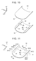
- FIG. 10 is an exploded perspective view of a hood 80 as a vehicle exterior design member according to a third example embodiment of the invention.
- FIG. 11 is a perspective view of this hood 80.
- the hood 80 is used to open and close an upper end opening of a power unit compartment provided in a front portion of the vehicle, and includes an inner panel (a hood inner panel) 82 and an outer panel (a hood outer panel) 84 that is joined to an upper side of the inner panel 82.
- Openings 86 and 88 are formed in positions slightly to the vehicle rear side of the center in the vehicle front-rear direction in left and right end portions, respectively, of the inner panel 82. These openings 86 and 88 are used as working holes, drainage holes, wiring holes, or reference holes or the like, for example.
- this hood 80 includes a pair of front and rear outer edge outer panels (reinforcing members) 90 and 92 that are partially joined to a left edge portion of the inner panel 82, and a pair of front and rear outer edge outer panels (reinforcing members) 94 and 96 that are partially joined to the right edge portion of the inner panel 82.
- These outer edge outer panels 90, 92, 94, and 96 are arranged between the inner panel 82 and the outer panel 84.
- the inner panel 82 and the outer edge outer panels 90, 92, 94, and 96 are made of resin (e.g., CFRP), and the outer panel 84 is made of resin (e.g., polypropylene) that has a lower strength than the inner panel 82 and the outer edge outer panels 90, 92, 94, and 96.
- resin e.g., CFRP
- resin e.g., polypropylene
- the outer edge outer panel 90 is joined to a front portion side of a left edge portion of the hood 80, and the outer edge outer panel 92 is joined to a rear portion side of the left edge portion of the hood 80. Also, the outer edge outer panel 94 is joined to a front portion side of a right edge portion of the hood 80, and the outer edge outer panel 96 is joined to a rear portion side of the right edge portion of the hood 80.
- These outer edge outer panels 90, 92, 94, and 96 form a closed section with the inner panel 62.
- portions of the outer edge portion are first outer edge portions (high strength outer edge portions) 80A1, 80A2, 80A3, and 80A4 (80A) that are reinforced by the outer edge outer panels 90, 92, 94, and 96, and the other portions of the outer edge portion are second outer edge portions (low strength outer edge portions) 80B1 and 80B2 (80B) that are not reinforced by the outer edge outer panels 90, 92, 94, and 96, as shown in FIG. 11 .
- the second outer edge portion 80B1 is positioned between the first outer edge portion 80A1 and the first outer edge portion 80A2, and the second outer edge portion 80B2 is positioned between the first outer edge portion 80A3 and the first outer edge portion 80A4.
- the second outer edge portions 80B1 and 80B2 have a lower strength than the first outer edge portions 80A1, 80A2, 80A3, and 80A4.
- the openings 86 and 88 described above are positioned near the centers of the left and right second outer edge portions 80B1 and 80B2 in the vehicle width direction.
- the opening 86 on the left side is arranged adjacent to both a boundary portion 80C1 between the first outer edge portion 80A1 and the second outer edge portion 80B1, and a boundary portion 80C2 between the first outer edge portion 80A2 and the second outer edge portion 80B1.
- the opening 88 on the right side is arranged adjacent to both a boundary portion 80C3 between the first outer edge portion 80A3 and the second outer edge portion 80B2, and a boundary portion 80C4 between the first outer edge portion 80A4 and the second outer edge portion 80B2.
- the boundary portions 80C1, 80C2, 80C3, and 80C4 (80C) between the first outer edge portions 80A1, 80A2, 80A3, and 80A4 (80A) and the second outer edge portions 80B1 and 80B2 (80B) where there is a strength difference are set at portions weakened by being adjacent to the openings 86 and 88.
- stress concentrates near the boundary portions 80C1, 80C2, 80C3, and 80C4 of the hood 80, so the hood 80 tends to deform at or near these boundary portions.
- the deformation mode of the hood 80 is able to be stabilized such that the hood 80 breaks around a horizontal line H in FIG. 11 .
- the deformation positions of the side door main body 60 and the hood 80 in the second and third example embodiments are merely examples. Also, there may be cases in which it may actually be preferable not to apply the structure of the invention to a vehicle exterior design part such as the side door main body or the hood.
- FIG. 12 is an exploded perspective view of a back door main body 100 as a vehicle exterior design part according to a fourth example embodiment of the invention.
- FIG. 13 is a perspective view of this back door main body 100.
- This back door main body 100 forms a main body portion of a back door of a vehicle, and includes an inner panel (a door inner panel) 102, and an outer panel (a door outer panel) 104 that is joined to a vehicle outside (vehicle rear side) of the inner panel 102.
- the inner panel 102 is made of resin (e.g., CFRP)
- the outer panel 104 is made of resin (e.g., polypropylene) that has a lower strength than the inner panel 102.
- Window openings 106 and 108 that are closed off by back door glass are formed in an upper portion of the inner panel 102 and the outer panel 104.
- a pair of left and right openings 110 and 112 are formed in a vertically center portion of the outer panel 104 below the window opening 108.
- These openings 110 and 112 are lamp mounting holes for mounting lamps such as tail lamps to the outer panel 104.
- a dimension W2 in the vehicle width direction of each opening 110 and 112 is set to equal to or greater than 1/10 of a dimension W1 in the vehicle width direction of the outer panel 104, for example. That is, the total width dimension W2 of the left and right openings 110 and 112 is set to equal to or greater than 1/5 of the width dimension W1 of the outer panel 104. Accordingly, the outer panel 104 is much weaker at the height where the openings 110 and 112 are formed.
- this back door main body 100 includes a metal reinforcement 114 as a reinforcing member.
- This reinforcement 114 is formed in a generally inverted U-shape that is open on the vehicle lower side, and is connected to an upper edge portion, an upper portion side of a left edge portion, and an upper portion side of a right edge portion of the inner panel 102. Any of various methods such as a bolted connection or adhesion may be applied as the connecting method of the reinforcement 114.
- a portion of an outer edge portion is a first outer edge portion (a high strength outer edge portion) 100A that is reinforced by the reinforcement 114, and the other portion (the remaining portion) of the outer edge portion is a second outer edge portion (a low strength outer edge portion) 100B that is not reinforced by the reinforcement 114.
- This second outer edge portion 100B has a lower strength than the first outer edge portion 100A.
- the first outer edge portion 100A is arranged on a vehicle upper side, and on both sides in the vehicle width direction, of the window openings 106 and 108, and left and right lower end portions of the first outer edge portion 100A are boundary portions 100C1 and 100C2 between the first outer edge portion 100A and the second outer edge portion 100B. These boundary portions 100C1 and 100C2 (100C) are positioned farther to the lower end side of the inner panel 102 than the window openings 106 and 108, and are arranged adjacent to the left and right openings 110 and 112.
- the boundary portions 100C1 and 100C2 between the first outer edge portion 100A and the second outer edge portion 100B where there is a strength difference are set at portions weakened by being adjacent to the openings 110 and 112.
- stress concentrates near the boundary portions 100C1 and 100C2 of the back door main body 100, so the back door main body 100 tends to deform at these boundary portions 100C1 and 100C2.
- the deformation mode of the back door main body 100 is able to be stabilized.
Abstract
Description
- The invention relates to a vehicle exterior design member in which an inner panel and an outer panel are made of resin.
- Japanese Patent Application Publication
JP 2007-313919 A - However, with the resin panel described above, the composite material must be made different in one part, so manufacturing is complex. Also, the exterior design member for a vehicle is formed by joining together a plurality of panels formed in predetermined shapes, so the member formed by the plurality of panels being joined together needs to have a stabilized deformation mode.
- The invention thus provides a vehicle exterior design member and a vehicle back door that contributes to the stabilization of the deformation mode, in a structure in which an inner panel made of resin and an outer panel made of resin are joined together.
- A first aspect of the invention relates to a vehicle exterior design member, comprising: an inner panel made of resin (e.g. CFRP (carbon-fiber-reinforced plastic)); an outer panel made of resin (e.g. polypropylene) that is joined to the inner panel; at least one of the inner panel and the outer panel having an opening or weak portion; a first outer edge portion that is reinforced by a reinforcing member (also made of e.g. CFRP) and forms a portion of an outer edge portion; and a second outer edge portion that has a lower strength than the first outer edge portion and forms another portion of the outer edge portion. The opening or the weak portion is arranged adjacent to a boundary portion between the first outer edge portion and the second outer edge portion.
- With this vehicle exterior design member, an opening or weak portion is formed in or on at least one of the panels of a vehicle exterior design member in which an inner panel made of resin and an outer panel made of resin are joined together. A portion of the outer edge portion of this vehicle exterior design member is a first outer edge portion, and another portion of the outer edge portion of the vehicle exterior design member is a second outer edge portion. The first outer edge portion is reinforced by a reinforcing member, and has a higher strength than the second outer edge portion. Also, the boundary portion between the first outer edge portion and the second outer edge portion is arranged adjacent to the opening or the weak portion. That is, the boundary portion between the first outer edge portion and the second outer edge portion where there is a strength difference is weakened by being adjacent to the opening or the weak portion. As a result, when a collision or the like occurs, the vehicle exterior design member tends to deform at or near this boundary portion, which contributes to the stabilization of the deformation mode.
- The term "arranged adjacent" in the invention means, for example, that the boundary portion and the opening or weak portion are arranged such that when the vehicle exterior design member deforms at or near the boundary portion as described above, this deformation location reaches (extends) to at least the opening or the weak portion.
- The reinforcing member may be an outer edge outer panel made of resin, and the first outer edge portion may include a closed section in which the outer edge outer panel is joined to an outer edge portion of the inner panel.
- With this vehicle exterior design member, the first outer edge portion forms a closed section by the resin outer edge outer panel that is a reinforcing member being joined to the outer edge portion of the resin inner panel. As a result, weight is able to be reduced compared to when a metal reinforcement or the like is used as a reinforcing member.
- An open sectional portion having an open sectional shape may be formed on the outer edge portion of the inner panel, and the closed section may be formed by the outer edge outer panel and a portion of the open sectional portion.
- With this vehicle exterior design member, the closed section of the first outer edge portion is formed by the outer edge outer panel, and the portion of the open sectional portion formed on the outer edge portion of the inner panel. Having the open sectional portion formed on the outer edge portion of the inner panel in this way enables the strength of the inner panel to be increased, so the strength of the vehicle exterior design member is able to be ensured mainly by the inner panel. Consequently, the degree of freedom in design of the outer panel is able to be improved.
- The term "open sectional shape" in the invention refers to, for example, a shape in which a portion of a cross-section is open, such as a hat-shaped sectional shape, a generally U-shaped sectional shape, a generally C-shaped sectional shape, or a generally V-shaped sectional shape.
- The outer panel may be made of resin that has a lower strength than the resin of which the inner panel and the outer edge outer panel are made.
- Because the outer panel is made of resin that has a lower strength than the resin of which the inner panel and the outer edge outer panel are made, the outer panel has less of an effect on the deformation mode (fracture mode) of the vehicle exterior design member. Therefore, the deformation mode of the vehicle exterior design member is able to be determined mainly by the inner panel and the outer edge outer panel, so the deformation mode of the vehicle exterior design member is able to be easily set (designed).
- The opening may be formed in at least one of the inner panel and the outer panel, and the opening may have another function or use in addition to weakening the boundary portion.
- With this vehicle exterior design member, the opening formed in at least one of the inner panel and the outer panel is arranged adjacent to the boundary portion between the first outer edge portion and the second outer edge portion, so the boundary portion is weakened. Because this opening has a function or use other than weakening the boundary portion as described above (e.g., the opening may also serve as a window hole, a lamp mounting hole, a working hole, a drainage hole, a wiring hole, or a reference hole), it is not necessary to form a special opening or the like to weaken the boundary portion.
- A deformation starting point portion that will be a starting point of deformation of the boundary portion may be formed on the boundary portion.
- When the deformation starting point portion that will be the starting point of deformation of the boundary portion between the first outer edge portion and the second outer edge portion is formed on the boundary portion, the boundary portion can be made to deform with this deformation starting point portion as the starting point, which further contributes to the stabilization of the deformation mode.
- The inner panel may be a door inner panel of a back door of a vehicle, and the outer panel may be a door outer lower panel that is joined to a lower portion of the door inner panel. The first outer edge portion may be formed with the reinforcing member connected to an upper edge portion, a left edge portion, and a right edge portion of a first window opening formed in an upper portion of the door inner panel. Left and right lower end portions of the first outer edge portion that are positioned farther to a lower end side of the door inner panel than the first window opening may each form a boundary portion between the first outer edge portion and the second outer edge portion.
- With this vehicle exterior design member, the door inner panel of the back door of the vehicle is made of resin. A resin door outer lower door panel is joined to the lower portion of this door inner panel, and a first window opening is formed in an upper portion of this door inner panel. The reinforcing member is connected to the upper edge portion, the left edge portion, and the right edge portion of this first window opening. Thus, the first outer edge portion that has a higher strength than the second outer edge portion is formed. The left and right lower end portions of this first outer edge portion are both boundary portions between the first outer edge portion and the second outer edge portion. These left and right boundary portions are arranged adjacent to an opening or weak portion formed in at least one of the door inner panel and the door outer lower panel. As a result, the left and right boundary portions are weakened. Therefore, when a rear end collision or the like occurs, the door inner panel tends to deform at or near the left and right boundary portions. These left and right boundary portions are positioned farther to the lower portion side of the door inner panel than the first window opening, so the door inner panel is able to be prevented from inadvertently deforming at the left and right edge portions or the like of the window opening.
- A second window opening as the opening may be smaller than the first window opening and be formed extending between left and right lower end portions of the first outer edge portion, in the door inner panel.
- Accordingly, the second window opening is formed between the left and right lower end portions of the first outer edge portion that are positioned farther to the lower end side of the door inner panel than the first window opening, i.e., extending between the left and right boundary portions between the first outer edge portion and the second outer edge portion, in the door inner panel. This second window opening improves the rear visibility of the vehicle. Moreover, because the left and right boundary portions are weakened by the second window opening that improves the rear visibility of the vehicle in this way, there is no need to form a special opening or the like to weaken the left and right boundary portions.
- A pair of left and right openings may be formed in the outer door panel below the first window opening, and the boundary portions may be arranged adjacent to the left and right openings. The pair of left and right openings may be formed in a vertically center portion of the outer panel. These openings may be lamp mounting holes for mounting lamps such as tail lamps to the outer panel. A dimension in the vehicle width direction of each opening may be set to equal to or greater than 1/10 of a dimension in the vehicle width direction of the outer panel, for example. That is, the total width dimension of the left and right openings may be set to equal to or greater than 1/5 of the width dimension of the outer panel. Accordingly, the outer panel is much weaker at the height where the openings are formed.
- A second aspect of the invention relates to a back door of a vehicle, comprising: a door inner panel made of resin, in which a second window opening that is long in a vehicle width direction, is smaller than a first window opening, and is formed below the first window opening; a door outer lower panel made of resin, which is joined to the door inner panel below the second window opening; and a door outer upper panel that is made of resin and is joined to an upper edge portion, a left edge portion, and a right edge portion of the first window opening in the door inner panel. The door outer upper panel and the door inner panel forms a closed sectional structural portion in which left and right end portions of the closed sectional structural portion are arranged adjacent to both outsides in the vehicle width direction of the second window opening.
- With this back door, a second window opening that is long in the vehicle width direction, is smaller than the first window opening, and is formed below the first window opening, in the door inner panel made of resin, and the door outer lower panel made of resin is joined to the door inner panel below the second window opening. Also, the resin door outer upper panel and the door inner panel forms a closed sectional structural portion is joined to the upper edge portion, the left edge portion, and the right edge portion of the first window opening in this door inner panel. The left and right lower end portions of this closed sectional structural portion are arranged adjacent to both outsides in the vehicle width direction of the second window opening. That is, the boundary portion (the left and right lower end portions) where the sectional structure changes is weakened by being adjacent to the second window opening. As a result, when a rear end collision or the like of the vehicle occurs, the door inner panel tends to deform at or near these left and right lower end portions, which contributes to the stabilization of the deformation mode.
- The inner panel may be is a side door inner panel of a side door of a vehicle, the outer panel may be a side door outer panel that is joined to a lower portion of the side door inner panel; a front first outer edge portion may be formed with a reinforcing member joined to a front edge portion and a front side portion of a lower edge portion of the door inner panel, and a rear first outer edge portion may be formed with a reinforcing member joined to a rear edge portion and a rear side portion of a lower edge portion of the side door inner panel; the second outer edge portion may be formed between the front and rear first outer edge portions; and the opening may be arranged adjacent to each of a boundary portion between the front first outer edge portion and the second outer edge portion, and a boundary portion between the rear first outer edge portion and the second outer edge portion. Thus, the configuration according to the present invention is also applicable to a side door of a vehicle.
- The inner panel may be a hood inner panel of a hood of a vehicle; the outer panel may be a hood outer lower panel that is joined to an upper side of the hood inner panel; first outer edge portions may be reinforced by a pair of front and rear outer edge outer panels joined to a front portion side of a left edge portion of the hood inner panel and a rear portion side of a left edge portion of the hood inner panel, and by a pair of front and rear outer edge outer panels joined to a front portion side of a right edge portion of the hood inner panel and a rear portion side of the right edge portion of the hood inner panel; second outer edge portions may be positioned between the pair of front and rear outer edge outer panels joined to the left edge portion of the hood inner panel and between the pair of front and rear outer edge outer panels joined to the right edge portion of the hood inner panel; and openings may be positioned near the centers of the second outer edge portions in the vehicle width direction. Thus, the configuration according to the present invention is also applicable to a hood of a vehicle.
- The term "arranged adjacent" in the invention means, for example, that the left and right lower end portions and the second window opening are arranged such that when the back door deforms at or near the left and right lower end portions described above, this deformation location reaches (extends) to at least the second window opening.
- As described above, the vehicle exterior design member and the vehicle back door according to the invention contribute to the stabilization of the deformation mode, in a structure in which an inner panel made of resin and an outer panel made of resin are joined together.
- Features, advantages, and technical and industrial significance of exemplary embodiments of the invention will be described below with reference to the accompanying drawings, in which like numerals denote like elements, and wherein:
-
FIG. 1 is a perspective view of a back door of a vehicle according to a first example embodiment of the invention, viewed diagonally from the rear left; -
FIG. 2 is a perspective view of a back door main body of the back door before a back door glass and back door lower glass are mounted to the back door main body; -
FIG. 3 is a perspective view of a door inner panel of the back door main body before a door outer lower panel is attached to the door inner panel; -
FIG. 4 is an exploded perspective view of the door inner panel and a door outer upper panel; -
FIG. 5 is an enlarged sectional view of a cross-section taken along line V - V inFIG. 1 ; -
FIG. 6 is an enlarged sectional view of a cross-section taken along line VI - VI inFIG. 1 ; -
FIG. 7 is an enlarged sectional view of a region denoted by reference character A inFIG. 2 ; -
FIG. 8 is an exploded perspective view of a side door main body as a vehicle exterior design part according to a second example embodiment of the invention; -
FIG. 9 is a perspective view of the side door main body; -
FIG. 10 is an exploded perspective view of a hood as a vehicle exterior design part according to a third example embodiment of the invention; -
FIG. 11 is a perspective view of the hood; -
FIG. 12 is an exploded perspective view of a back door main body as a vehicle exterior design part according to a fourth example embodiment of the invention; and -
FIG. 13 is a perspective view of the back door main body. - Hereinafter, a back door
main body 10 as a vehicle exterior design member according to a first example embodiment of the invention, and a vehicleback door 12 of a vehicle that includes this back doormain body 10, will be described with reference toFIGS. 1 to 7 . In the drawings, arrow FR indicates a forward direction (advancing direction) with respect to a vehicle, arrow UP indicates an upward direction with respect to the vehicle, and arrow OUT indicates an outside in a vehicle width direction. Hereinafter, unless otherwise specified, when directions of front and rear, left and right, and up and down are used, they will refer to front and rear in a vehicle longitudinal direction, left and right in a vehicle lateral direction (i.e., the vehicle width direction), and up and down in a vehicle vertical direction, respectively. -
FIG. 1 is a perspective view of theback door 12 according to the example embodiment viewed diagonally from the rear left. Thisback door 12 is a door that opens and closes a back door opening, not shown, formed in a rear end portion of a vehicle body. An upper end portion of theback door 12 is hinge connected to the vehicle body with the vehicle width direction as the axial direction. Thus, theback door 12 is supported by the vehicle body so as to be able to open and close. Theback door 12 is formed having a general L-shape when viewed from a side of the vehicle, and includes a doorupper portion 12U that extends gently downward at an angle toward the rear of the vehicle from an upper end portion of theback door 12, and a doorlower portion 12L that hangs down toward a vehicle lower side from a rear end portion of the doorupper portion 12U. - This
back door 12 has a back doormain body 10 made of resin (seeFIG. 2 ), aback door glass 14 as a window glass, a back door lower glass 16 (hereinafter, simply referred to as "lower glass 16") as a small window glass, and arear spoiler 18. Theback door glass 14 is arranged on the doorupper portion 12U, and thelower glass 16 is arranged on an upper portion of the doorlower portion 12L. Therear spoiler 18 is arranged between theback door glass 14 and thelower glass 16. Theback door glass 14, thelower glass 16, and therear spoiler 18 are all attached to the back doormain body 10. -
FIG. 2 is a perspective view of a back doormain body 10 before thelower glass 16 and therear spoiler 18 are attached to the back door main body. This back doormain body 10 includes a doorinner panel 20 made of resin, a door outerlower panel 22 made of resin that is joined to a lower portion of the doorinner panel 20, and a door outerupper panel 24 made of resin that serves as an outer edge outer panel (reinforcing member) that is joined to an upper portion side of the doorinner panel 20. Hereinafter, the doorinner panel 20 will be referred to as the "inner panel 20", the door outerlower panel 22 will be referred to as the "outerlower panel 22", and the door outerupper panel 24 will be referred to as the "outerupper panel 24". - Here, the
inner panel 20 and the outerupper panel 24 are made of CFRP (carbon-fiber-reinforced plastic) in which short carbon fibers are oriented randomly. Here, the outerlower panel 22 is made of polypropylene that is a resin having a lower strength than the CFRP described above. This outerlower panel 22 forms an appearance design surface of the vehicle and does not contribute much to the strength and rigidity of the back doormain body 10. That is, the strength and rigidity of the back doormain body 10 are mainly ensured by theinner panel 20 and the outerupper panel 24. -
FIG. 3 is a perspective view of theinner panel 20 before the outerlower panel 22 is joined thereto, andFIG. 4 is a perspective view of theinner panel 20 before the outerlower panel 22 and the outerupper panel 24 are joined thereto. As shown inFIGS. 2 to 4 , theinner panel 20 is a relatively large panel member that forms the main portion of the back doormain body 10. Anupper portion 20U of thisinner panel 20 is arranged on the doorupper portion 12U, and alower portion 20L of theinner panel 20 is arranged on the doorlower portion 12L. - A
window opening 26 is formed in theupper portion 20U of theinner panel 20. Thiswindow opening 26 is formed in a long, generally rectangular shape that is long in the vehicle width direction. Also, a small window opening (a window hole) 28 that is more elongated than thewindow opening 26 is formed long in the vehicle width direction on an upper end side of thelower portion 20L of theinner panel 20, below thewindow opening 26. Thewindow opening 26 and thesmall window opening 28 are openings for vehicle rear visibility, which are closed (covered) from the vehicle outside by theback door glass 14 and thelower glass 16. - An outer edge portion of the
inner panel 20 is an opensectional portion 21 that has an open sectional shape that is open to the vehicle outside. This opensectional portion 21 includes anupper edge component 21A, alower edge component 21B, aleft edge component 21C, and aright edge component 21D that form the upper, lower, left, and right edge portions of theinner panel 20, and is formed along the entire periphery of the outer edge portion of theinner panel 20. This opensectional portion 21 improves the strength and rigidity of theinner panel 20. - The
upper edge component 21A forms an upper edge portion of thewindow opening 26. Theleft edge component 21C and theright edge component 21D form the left and right edge portions, respectively, of thewindow opening 26 at theupper portion 20U of theinner panel 20, as well as form the left and right edge portions, respectively, of thesmall window opening 28 at thelower portion 20L of theinner panel 20. Acenter connecting portion 32 that extends in the vehicle width direction is formed near the vertically center portion of theinner panel 20, between thewindow opening 26 and thesmall window opening 28. Theleft edge component 21C and theright edge component 21D are integrally connected by thiscenter connecting portion 32. Thecenter connecting portion 32 forms a lower edge portion of thewindow opening 26 and an upper edge portion of thesmall window opening 28. - A pair of upper and lower bulging
portions lower portion 20L of theinner panel 20. These bulgingportions small window opening 28. These bulgingportions lower portion 20L of theinner panel 20. - The outer
lower panel 22 described above is arranged on the vehicle outside (vehicle rear side) of thelower portion 20L of theinner panel 20. This outerlower panel 22 is joined to theinner panel 20 at predetermined locations on the outer edge portion and center side. Thelower portion 20L of theinner panel 20 is covered from the vehicle outside by this outerlower panel 22. However, this outerlower panel 22 is arranged below thesmall window opening 28 so that thesmall window opening 28 is exposed to the vehicle outside. An upper protrudingportion 22A that protrudes upward is formed on both left and right end portions of the upper edge portion of the outerlower panel 22. - The outer
upper panel 24 described above is arranged on the vehicle outside (on the vehicle rearward inclined upper side) of theupper portion 20U of theinner panel 20. The outerupper panel 24 includes aleft panel 23 and aright panel 25 that are formed split, as shown inFIG. 4 . Theleft panel 23 and theright panel 25 are formed in general L-shapes and are bilaterally symmetrical, and are joined together by a production adhesive or the like in a state in which the edge portions on the vehicle width direction center side are overlapped with each other. As a result, the outerupper panel 24 is formed in an overall general U-shape that is open on the vehicle rear side. - This outer
upper panel 24 is overlapped from the vehicle outside with theupper edge component 21A, the upper portion side of theleft edge component 21C, and the upper portion side of theright edge component 21D, of the opensectional portion 21 of theinner panel 20. That is, the outerupper panel 24 is arranged on the vehicle upper side and both sides in the vehicle width direction, of thewindow opening 26. The back door main body 10 (the back door 12) according to this example embodiment is formed basically bilaterally symmetrical, so only a cross-section on the vehicle right side shown inFIGS. 5 and6 will be described below. A description of a cross-section on the vehicle left side will be omitted. - In the cross-section shown in
FIG. 5 (i.e., the cross-section taken along line V - V inFIG. 1 ), the outerupper panel 24 includes an outer sideupper wall portion 24A, an outer sideside wall portion 24B, and an outer sideinner wall portion 24C. The outer sideupper wall portion 24A is arranged parallel or substantially parallel to theback door glass 14. The outer sideside wall portion 24B is bent at a right angle or a substantially right angle in a direction away from theback door glass 14. The outer sideinner wall portion 24C is bent at an obtuse angle toward the vehicle lower side from an end portion on the extending direction side of the outer sideside wall portion 24B. - Also, in the cross-section shown in
FIG. 5 , the opensectional portion 21 of theinner panel 20 includes an inner sideouter wall portion 20A and an inner sidebottom wall portion 20B. The inner sideouter wall portion 20A is arranged farther toward the outside in the vehicle width direction than the outer sideside wall portion 24B, and is parallel to the outer sideside wall portion 24B. The inner sidebottom wall portion 20B extends in an L-shape from an end portion on the vehicle lower side of the inner sideouter wall portion 20A. The inner sideouter wall portion 20A extends to the outer sideupper wall portion 24A, and then bends toward the outside in the vehicle width direction and becomes an inner side outsideflange portion 20C. Moreover, the inner sidebottom wall portion 20B extends to the outer sideinner wall portion 24C, and then bends toward the vehicle upper side and becomes an inner side insidewall portion 20D. - A portion of the outer side
upper wall portion 24A described above that is on the outer side in the vehicle width direction is an outer side flange portion 24A1. A lower surface of this outer side flange portion 24A1 is joined to an upper surface of the inner side outsideflange portion 20C by aproduction adhesive 38. Also, an inside surface in the vehicle width direction of the outer sideinner wall portion 24C is joined to an outside surface in the vehicle width direction of the inner side insidewall portion 20D by aproduction adhesive 40. As a result, a closed section is formed by the outerupper panel 24 and a portion of the opensectional portion 21 of theinner panel 20. - Further, the
back door glass 14 is joined to an upper surface of the outer side flange portion 24A1 by aperipheral component adhesive 42. Thisperipheral component adhesive 42 is set in a ring shape along the outer edge portion of theback door glass 14. Adam member 44 that is a water stopping member (a seal member) is arranged to the outside of the outer periphery of theperipheral component adhesive 42. Thisdam member 44 is set in a ring shape along the outer edge portion of theback door glass 14. - The outer
upper panel 24 described above is provided mainly on theupper portion 20U side of the back doormain body 10, as shown inFIGS. 2 and3 . The outerupper panel 24 is not present in the cross-section shown inFIG. 6 (i.e., the cross-section taken along line VI - VI inFIG. 1 ). In the cross-section shown inFIG. 6 , the opensectional portion 21 of theinner panel 20 includes the inner sideouter wall portion 20A, the inner sidebottom wall portion 20B, the inner side outsideflange portion 20C, and the inner side insidewall portion 20D described above. Moreover, an inner side insideflange portion 20E extends toward the center side in the vehicle width direction from a rear end portion of the inner side insidewall portion 20D. Thelower glass 16 is joined to a rear surface of the inner side outsideflange portion 20C by aperipheral component adhesive 46. Thisperipheral component adhesive 46 is set in a ring shape along the outer edge portion of thelower glass 16. As shown inFIGS. 5 and6 , when theback door 12 is closed, the inner sidebottom wall portion 20B is abutted against aweather strip 50 that is attached to avehicle body 48. - Of the back door
main body 10 having the structure described above, a portion of the outer edge portion is a first outer edge portion (a high strength outer edge portion) 10A that is reinforced by the outerupper panel 24, and the other portion (the remaining portion) of the outer edge portion is a second outer edge portion (a low strength outer edge portion) 10B that is not reinforced by the outer upper panel 24 (cf.Fig. 1 ). In the firstouter edge portion 10A, the opensectional portion 21 of theinner panel 20 that is made of CFRP and the outerupper panel 24 that is made of CFRP are joined together to form a closed section. The strength and rigidity of the firstouter edge portion 10A are improved by this closed section. This firstouter edge portion 10A corresponds to the "closed sectional structural portion" described in the claims. - Meanwhile, in the second
outer edge portion 10B, the outerupper panel 24 that is made of CFRP is not present, and the strength and rigidity of the secondouter edge portion 10B is ensured mainly by the opensectional portion 21 of theinner panel 20. Therefore, the strength and rigidity of the secondouter edge portion 10B are set lower than the strength and rigidity of the firstouter edge portion 10A. - The first
outer edge portion 10A is arranged on the vehicle upper side and both sides in the vehicle width direction, of thewindow opening 26, with the left and right lower end portions (rear end portions) being boundary portions 10C1 and 10C2 (10C) between the firstouter edge portion 10A and the secondouter edge portion 10B. These boundary portions 10C1 and 10C2 are positioned farther to the lower end side of theinner panel 20 than thewindow opening 26. The positions of these boundary portions 10C1 and 10C2 match the positions of the left and right lower end portions (rear end portions) 24L1 and 24L2 of the outerupper panel 24. - The outer
upper panel 24 extends farther toward the upper end side of thelower portion 20L than the lower end (rear end) of theupper portion 20U of theinner panel 20, and left and right lower end portions 24L1 and 24L2 are positioned on both sides of thesmall window opening 28 in the vehicle width direction. Thissmall window opening 28 is formed extending between the left and right boundary portions 10C1 and 10C2, and the left and right boundary portions 10C1 and 10C2 are arranged adjacent to, on the outsides in the vehicle width direction of, thesmall window opening 28. The left and right lower end portions 24L1 and 24L2 of the outerupper panel 24 are arranged spaced apart, on the vehicle upper side, from the upper end portions of the left and right upper protrudingportions 22A of the outerlower panel 22. - Also, a pair of left and right recessed
portions 52 and 54 (seeFIG. 7 ; not shown in the other drawings) that serve as deformation starting point portions are formed on each of the left and right boundary portions 10C1 and 10C2. These recessedportions flange portion 20C and part of the inner side insideflange portion 20E of the opensectional portion 21 being formed depressed toward the vehicle front side, and have open sectional shapes (generally C-shaped sectional shapes) that are open on the vehicle rear side when viewed from the vehicle width direction. The recessedportions upper panel 24 from the vehicle front side. - Next, the operation and effects of the example embodiment will be described.
- With the
back door 12 having the structure described above, theinner panel 20, the outerlower panel 22, and the outerupper panel 24 that form the back doormain body 10 are all made of resin, so weight reduction is able to be achieved. However, when the back doormain body 10 is made of resin in an attempt to reduce the weight, deformation in the plastic region of the resin is small, so with a collision in which a large load is applied such as a rear collision, cracking tends to occur. In particular, when fiber-reinforced resin in which the fibers are oriented randomly is used, the location where cracking will occur is difficult to predict. Therefore, from the viewpoint of stable occupant protection, it is important to take into consideration the stability of the deformation mode. - Regarding this, in this example embodiment, the outer edge portion of the back door
main body 10 is formed by the firstouter edge portion 10A on the vehicle upper side and the secondouter edge portion 10B on the vehicle lower side. The firstouter edge portion 10A is reinforced by the outerupper panel 24 that is joined to theinner panel 20, and thus has a higher strength than the secondouter edge portion 10B. Also, the boundary portions 10C1 and 10C2 between the firstouter edge portion 10A and the secondouter edge portion 10B are arranged adjacent to thesmall window opening 28 formed in theinner panel 20. - In this way, the left and right boundary portions 10C1 and 10C2 that are the boundary portions between the first
outer edge portion 10A and the secondouter edge portion 10B where there is a strength difference, i.e., portions where the sectional structure of the outer edge portion of the back doormain body 10 changes, are set at portions that are weakened by being adjacent to thesmall window opening 28. Therefore, when a rear end collision of the vehicle occurs, for example, stress concentrates near the left and right boundary portions 10C1 and 10C2 of the back doormain body 10, so the back doormain body 10 tends to deform (tends to break) at or near the left and right boundary portions 10C1 and 10C2, which contributes to the stabilization of the deformation mode. In addition, because the deformation mode is stabilized by the structure of the back doormain body 10 based on the shape of the plurality of panels that are joined together, the deformation mode is able to be more effectively stabilized than it is with a structure in which the composite materials of individual panels are made to partially differ. - Also, in this example embodiment, the upper edge portion, the left edge portion, and the right edge portion of the
window opening 26 in theinner panel 20 are reinforced by the outerupper panel 24, while the boundary portions 10C1 and 10C2, the positions of which are determined by the arrangement of the left and right lower end portions 24L1 and 24L2 of the outerupper panel 24, are positioned farther to the lower end side of theinner panel 20 than thewindow opening 26. As a result, theinner panel 20 will not inadvertently deform at the left and right edge portions and the like of thewindow opening 26. - That is, in this example embodiment, the position of the end portion of the outer upper panel 24 (the outer edge outer panel; a reinforcing member) is set to a portion that is weakened by being adjacent to the
window opening 28, while reinforcing the portion where inadvertent deformation is predicted in the back doormain body 10, with the outerupper panel 24. As a result, the planned deformation location of the back doormain body 10 is able to be effectively specified. - Also, in this example embodiment, the first
outer edge portion 10A forms a closed section by the resin outerupper panel 24 that is a reinforcing member being joined to the outer edge portion of the resininner panel 20. As a result, the firstouter edge portion 10A is able to be efficiently made stronger than it is when a metal reinforcement or the like is used as a reinforcing member, which contributes to a reduction in weight. - Further, in this example embodiment, the open
sectional portion 21 that has an open sectional shape is formed on the outer edge portion of theinner panel 20, and a closed section of the firstouter edge portion 10A is formed by the outerupper panel 24 and a portion (on the upper portion side) of the opensectional portion 21. In this way, the strength of theinner panel 20 is able to be increased by the opensectional portion 21 being formed on the outer edge portion of theinner panel 20, so the strength of the back doormain body 10 is able to be ensured mainly by theinner panel 20. As a result, the degree of freedom in design of the outerlower panel 22 that forms the appearance design surface of the vehicle is able to be improved. - Further, in this example embodiment, the outer
lower panel 22 is made of resin (polypropylene) that has a lower strength than the resin (CFRP) that theinner panel 20 and the outerupper panel 24 are made of, so the outerlower panel 22 has less of an effect on the deformation mode (fracture mode) of the back doormain body 10. As a result, the deformation mode of the back doormain body 10 is able to be determined by mainly theinner panel 20 and the outerupper panel 24, so the deformation mode of the back doormain body 10 is able to be set (i.e., designed) easily. - Moreover, in this example embodiment, the
small window opening 28 is formed between the left and right lower end portions of the firstouter edge portion 10A positioned farther to the lower end side of theinner panel 20 than thewindow opening 26, i.e., between the left and right boundary portions 10C1 and 10C2 between the firstouter edge portion 10A and the secondouter edge portion 10B, in theinner panel 20. Thissmall window opening 28 improves the rear visibility of the vehicle. In addition, the left and right boundary portions 10C1 and 10C2 are weakened by thesmall window opening 28 that improves the rear visibility of the vehicle in this way, so there is no need to form a special opening or the like for weakening the left and right boundary portions 10C1 and 10C2. - Furthermore, in this example embodiment, the pair of left and right recessed
portions portions portions portions main body 10. - As described above, in this example embodiment, as a method of stabilizing the deformation mode of the back door
main body 10, the upper portion side of the outer edge portion of the back doormain body 10 is made a high strength closed section, while the lower end side of this outer edge portion is made an open section. By creating a strength difference between the upper portion side and the lower portion side of the back doormain body 10 in this way, the deformation mode is able to be stabilized by having the back doormain body 10 deformed at the boundary portions 10C1 and 10C2. Moreover, the left and right lower end portions 24L1 and 24L2 of the outerupper panel 24 that is necessary for forming the high strength closed section are set near thesmall window opening 28. Setting the position where the sectional structure changes near a weakened portion of theinner panel 20 in this way makes it possible to further stabilize the deformation mode. - Summing up, in a back door
main body 10, an outerupper panel 24 made of CFRP is joined to an upper portion of aninner panel 20 made of CFRP, and an outerlower panel 22 made of polypropylene is joined to a lower portion of theinner panel 20. Of an outer edge portion of this back doormain body 10, an upper portion side is a firstouter edge portion 10A that is reinforced by the outerupper panel 24, and a lower portion side is a secondouter edge portion 10B having a lower strength than the firstouter edge portion 10A. Also, a boundary portion 10C1, 10C2 between the firstouter edge portion 10A and the secondouter edge portion 10B where there is a strength difference in this way is set at a portion weakened by being adjacent to asmall window opening 28. - In the first example embodiment described above, the recessed
portions inner panel 20 at the boundary portions 10C1 and 10C2, but the invention is not limited to this. The deformation starting point portions may also be holes or the like. - Also, in the first example embodiment described above, the boundary portions 10C1 and 10C2 are weakened by the small window opening 28 (i.e., the opening) for vehicle rear visibility, but the invention is not limited to this. That is, a special opening to weaken the boundary portions may also be set.
- Also, in the first example embodiment described above, the outer lower panel 22 (i.e., the outer panel) is made of resin that has a lower strength than the
inner panel 20 and the outer upper panel 24 (i.e., the outer edge outer panel), but the invention is not limited to this. That is, the resin of which each of the panels is made may also be changed as appropriate. - Also, in the first example embodiment described above, the open
sectional portion 21 having an open sectional shape is formed on the outer edge portion of theinner panel 20, and the closed section of the firstouter edge portion 10A is formed by the outer upper panel 24 (i.e., the outer edge outer panel) and a portion of the opensectional portion 21, but the invention is not limited to this. For example, a closed section of the first outer edge portion may also be formed by an outer edge outer panel having an open sectional shape being joined to an outer edge portion of an inner panel formed in a flat plate shape. - Also, in the first example embodiment described above, the first
outer edge portion 10A forms a closed section by the outer upper panel 24 (i.e., the outer edge outer panel) being joined to the outer edge portion of theinner panel 20, but the invention is not limited to this. For example, an outer edge outer panel that has been strengthened by a plurality of ribs formed thereon may also be joined to the outer edge portion of the inner panel. - Moreover, in the first example embodiment described above, the boundary portions 10C1 and 10C2 are arranged adjacent to the small window opening 28 (i.e., the opening) formed in the
inner panel 20, but the invention is not limited to this. That is, the boundary portions 10C1 and 10C2 may also be arranged adjacent to a weak portion formed on at least one of theinner panel 20 and the outer lower panel 22 (i.e., the outer panel). This weak portion need only be weaker than the surrounding portion, and may be a thin portion that is thinner than the surrounding portion, for example. Also, a flat plate portion (a weak portion) formed in a flat plate shape may be surrounded by a surrounding portion on which ribs or the like have been formed. The foregoing supplemental description is also the same for the example embodiments described below. - Next, other example embodiments of the invention will be described. Structure and operation that are basically the same as those in the first example embodiment will be denoted by the same reference characters used in the first example embodiment, and descriptions thereof will be omitted.
-
FIG. 8 is an exploded perspective view of a side doormain body 60 as a vehicle exterior design member according to a second example embodiment of the invention. Also,FIG. 9 is a perspective view of this side doormain body 60. This side doormain body 60 forms a main body portion of a side door of a vehicle, and includes an inner panel (a side door inner panel) 62, and an outer panel (a side door outer panel) 64 that is joined to an outside, in the vehicle width direction, of a lower portion of theinner panel 62. - A
glass opening 66 that is closed off by a side door glass is formed in an upper portion of theinner panel 62. Also, anopening 68 that is sufficiently smaller than theglass opening 66 is formed in a portion that is slightly to the vehicle rear side of the center of a lower end portion of theinner panel 62 in the vehicle front-rear direction. Thisopening 68 is used as a working hole, a drainage hole, a wiring hole, or a reference hole or the like, for example. - Furthermore, this side door
main body 60 includes a pair of front and rear outer edge panels (reinforcing members) 70 and 72 that are partially joined to an outer edge portion of a lower portion of theinner panel 62. These outer edgeouter panels inner panel 62 and theouter panel 64. Theinner panel 62 and theouter edge panels outer panel 64 is made of resin (such as polypropylene) that has a lower strength than theinner panel 62 and theouter edge panels - Each of the pair of front and rear
outer edge panels outer panel 70 is joined to the front edge portion of the lower portion, and the front portion side of the lower edge portion, of theinner panel 62. The rear outer edgeouter panel 72 is joined to the rear edge portion of the lower portion, and the rear portion side of the lower edge portion, of theinner panel 62. Theseouter edge panels inner panel 62. - Of the side door
main body 60 having the structure described above, portions of the outer edge portion are first outer edge portions (high strength outer edge portion) 60A1 and 60A2 (60A) that are reinforced by theouter edge panels outer edge panels FIG. 9 . This secondouter edge portion 60B is formed between the first outer edge portions 60A1 and 60A2, and has a lower strength than the first outer edge portions 60A1 and 60A2. Theopening 68 described above is positioned above and near the secondouter edge portion 60B. Thisopening 68 is arranged adjacent to each of a boundary portion 60C1 between the first outer edge portion 60A1 and the secondouter edge portion 60B, and a boundary portion 60C2 between the first outer edge portion 60A2 and the secondouter edge portion 60B. - In this example embodiment as well, the boundary portions 60C1 and 60C2 (60C) between the second
outer edge portion 60B and the first outer edge portions 60A1 and 60A2 where there is a strength difference are set at portions weakened by being adjacent to theopening 68. Therefore, when a side collision of a vehicle or the like occurs, stress concentrates near the boundary portions 60C1 and 60C2 of the side doormain body 60, so the side doormain body 60 tends to deform at or near these boundary portions 60C1 and 60C2. As a result, the deformation mode of the side doormain body 60 is able to be stabilized such that the side doormain body 60 breaks around the vertical axis V inFIG. 9 . -
FIG. 10 is an exploded perspective view of ahood 80 as a vehicle exterior design member according to a third example embodiment of the invention. Also,FIG. 11 is a perspective view of thishood 80. Thehood 80 is used to open and close an upper end opening of a power unit compartment provided in a front portion of the vehicle, and includes an inner panel (a hood inner panel) 82 and an outer panel (a hood outer panel) 84 that is joined to an upper side of theinner panel 82. -
Openings inner panel 82. Theseopenings - Furthermore, this
hood 80 includes a pair of front and rear outer edge outer panels (reinforcing members) 90 and 92 that are partially joined to a left edge portion of theinner panel 82, and a pair of front and rear outer edge outer panels (reinforcing members) 94 and 96 that are partially joined to the right edge portion of theinner panel 82. These outer edgeouter panels inner panel 82 and theouter panel 84. Theinner panel 82 and the outer edgeouter panels outer panel 84 is made of resin (e.g., polypropylene) that has a lower strength than theinner panel 82 and the outer edgeouter panels - The outer edge
outer panel 90 is joined to a front portion side of a left edge portion of thehood 80, and the outer edgeouter panel 92 is joined to a rear portion side of the left edge portion of thehood 80. Also, the outer edgeouter panel 94 is joined to a front portion side of a right edge portion of thehood 80, and the outer edgeouter panel 96 is joined to a rear portion side of the right edge portion of thehood 80. These outer edgeouter panels inner panel 62. - Of the
hood 80 having the structure described above, portions of the outer edge portion are first outer edge portions (high strength outer edge portions) 80A1, 80A2, 80A3, and 80A4 (80A) that are reinforced by the outer edgeouter panels outer panels FIG. 11 . The second outer edge portion 80B1 is positioned between the first outer edge portion 80A1 and the first outer edge portion 80A2, and the second outer edge portion 80B2 is positioned between the first outer edge portion 80A3 and the first outer edge portion 80A4. The second outer edge portions 80B1 and 80B2 have a lower strength than the first outer edge portions 80A1, 80A2, 80A3, and 80A4. - The
openings opening 86 on the left side is arranged adjacent to both a boundary portion 80C1 between the first outer edge portion 80A1 and the second outer edge portion 80B1, and a boundary portion 80C2 between the first outer edge portion 80A2 and the second outer edge portion 80B1. Similarly, theopening 88 on the right side is arranged adjacent to both a boundary portion 80C3 between the first outer edge portion 80A3 and the second outer edge portion 80B2, and a boundary portion 80C4 between the first outer edge portion 80A4 and the second outer edge portion 80B2. - In this example embodiment as well, the boundary portions 80C1, 80C2, 80C3, and 80C4 (80C) between the first outer edge portions 80A1, 80A2, 80A3, and 80A4 (80A) and the second outer edge portions 80B1 and 80B2 (80B) where there is a strength difference are set at portions weakened by being adjacent to the
openings hood 80, so thehood 80 tends to deform at or near these boundary portions. As a result, the deformation mode of thehood 80 is able to be stabilized such that thehood 80 breaks around a horizontal line H inFIG. 11 . - The deformation positions of the side door
main body 60 and thehood 80 in the second and third example embodiments are merely examples. Also, there may be cases in which it may actually be preferable not to apply the structure of the invention to a vehicle exterior design part such as the side door main body or the hood. -
FIG. 12 is an exploded perspective view of a back doormain body 100 as a vehicle exterior design part according to a fourth example embodiment of the invention. Also,FIG. 13 is a perspective view of this back doormain body 100. This back doormain body 100 forms a main body portion of a back door of a vehicle, and includes an inner panel (a door inner panel) 102, and an outer panel (a door outer panel) 104 that is joined to a vehicle outside (vehicle rear side) of theinner panel 102. Theinner panel 102 is made of resin (e.g., CFRP), and theouter panel 104 is made of resin (e.g., polypropylene) that has a lower strength than theinner panel 102. -
Window openings inner panel 102 and theouter panel 104. Also, a pair of left andright openings outer panel 104 below thewindow opening 108. Theseopenings outer panel 104. A dimension W2 in the vehicle width direction of eachopening outer panel 104, for example. That is, the total width dimension W2 of the left andright openings outer panel 104. Accordingly, theouter panel 104 is much weaker at the height where theopenings - Further, this back door
main body 100 includes ametal reinforcement 114 as a reinforcing member. Thisreinforcement 114 is formed in a generally inverted U-shape that is open on the vehicle lower side, and is connected to an upper edge portion, an upper portion side of a left edge portion, and an upper portion side of a right edge portion of theinner panel 102. Any of various methods such as a bolted connection or adhesion may be applied as the connecting method of thereinforcement 114. - Of the back door
main body 100 having the structure described above, a portion of an outer edge portion is a first outer edge portion (a high strength outer edge portion) 100A that is reinforced by thereinforcement 114, and the other portion (the remaining portion) of the outer edge portion is a second outer edge portion (a low strength outer edge portion) 100B that is not reinforced by thereinforcement 114. This secondouter edge portion 100B has a lower strength than the firstouter edge portion 100A. - The first
outer edge portion 100A is arranged on a vehicle upper side, and on both sides in the vehicle width direction, of thewindow openings outer edge portion 100A are boundary portions 100C1 and 100C2 between the firstouter edge portion 100A and the secondouter edge portion 100B. These boundary portions 100C1 and 100C2 (100C) are positioned farther to the lower end side of theinner panel 102 than thewindow openings right openings - In this example embodiment as well, the boundary portions 100C1 and 100C2 between the first
outer edge portion 100A and the secondouter edge portion 100B where there is a strength difference are set at portions weakened by being adjacent to theopenings main body 100, so the back doormain body 100 tends to deform at these boundary portions 100C1 and 100C2. As a result, the deformation mode of the back doormain body 100 is able to be stabilized. - Heretofore, the invention has been described with reference to several example embodiments, but the invention may be carried out with various modifications without departing from the scope thereof. Also, the scope of the invention is not limited to the example embodiments described above.
Claims (12)
- A vehicle exterior design member (10; 60; 80; 100), comprising:an inner panel (20; 62; 82; 102) made of resin; andan outer panel (22; 64; 84; 104) made of resin that is joined to the inner panel (20; 62; 82; 102), at least one of the inner panel (20; 62; 82; 102) and the outer panel (22; 64; 84; 104) having an opening (28; 68; 86, 88; 106, 108) or weak portion,characterized by comprising:a first outer edge portion (10A; 60A; 80A; 100A) that is reinforced by a reinforcing member (24; 70, 72; 90, 92, 94, 96; 114) and forms a portion of an outer edge portion of the vehicle exterior design member (10; 60; 80; 100); anda second outer edge portion (10B; 60B; 80B; 100B) that has a lower strength than the first outer edge portion (10A; 60A; 80A; 100A) and forms another portion of the outer edge portion of the vehicle exterior design member (10; 60; 80; 100),wherein the opening (28; 68; 86, 88; 106, 108) or the weak portion is arranged adjacent to a boundary portion (10C; 60C; 80C; 100C) between the first outer edge portion (10A; 60A; 80A; 100A) and the second outer edge portion (10B; 60B; 80B; 100B).
- The vehicle exterior design member (10; 60; 80) according to claim 1, wherein
the reinforcing member (24; 70, 72; 90, 92, 94, 96) is an outer edge outer panel made of resin; and
the first outer edge portion (10A; 60A; 80A) includes a closed section in which the outer edge outer panel is joined to an outer edge portion of the inner panel (20; 62; 82). - The vehicle exterior design member (10) according to claim 2, wherein
an open sectional portion (21) having an open sectional shape is formed on the outer edge portion of the inner panel (20), and
the closed section is formed by the outer edge outer panel and a portion of the open sectional portion. - The vehicle exterior design member (10; 60; 80) according to claim 2 or 3, wherein the outer panel (22; 64; 84) is made of resin that has a lower strength than the resin of which the inner panel (20; 62, 82) and the outer edge outer panel are made.
- The vehicle exterior design member (10; 60; 80; 100) according to any one of claims 1 to 4, wherein
the opening (28; 68; 86, 88; 106, 108) is formed in at least one of the inner panel (20) and the outer panel (22); and,
in addition to its function of weakening the boundary portion (10C), the opening (28) serves as a window hole, a lamp mounting hole, a working hole, a drainage hole, a wiring hole, or a reference hole. - The vehicle exterior design member (10) according to any one of claims 1 to 5, wherein a deformation starting point portion (52, 54) that will be a starting point of deformation of the boundary portion (10C) is formed on the boundary portion (10C).
- The vehicle exterior design member (10; 100) according to any one of claims 1 to 6, wherein
the inner panel (20; 102) is a door inner panel of a back door (12) of a vehicle;
the outer panel (22; 104) is a door outer lower panel that is joined to a lower portion of the door inner panel;
the first outer edge portion (10A; 100A) is formed with the reinforcing member (24; 114) connected to an upper edge portion (21A), a left edge portion (21C), and a right edge portion (21D) of a first window opening (26, 106) formed in an upper portion of the door inner panel; and
left and right lower end portions of the first outer edge portion (10A; 100A) that are positioned farther to a lower end side of the door inner panel than the first window opening (26; 106) each form the boundary portion (10C; 100C) between the first outer edge portion (10A; 100A) and the second outer edge portion (10B; 100B). - The vehicle exterior design member (10) according to claim 7, wherein a second window opening as the opening (28) is smaller than the first window opening (26) and is formed extending between left and right lower end portions of the first outer edge portion (10A), in the door inner panel.
- The vehicle exterior design member (100) according to claim 7, wherein
a pair of left and right openings (110, 112) is formed in the outer door panel below the first window opening (106); and
the boundary portions (100C) are arranged adjacent to the left and right openings (110, 112). - The vehicle exterior design member (10) according to any one of claims 1 to 8, wherein
the inner panel (20) is a door inner panel (20) of a back door (12) of a vehicle, in which a second window opening (28) that is long in a vehicle width direction, is smaller than a first window opening (26), and is formed below the first window opening (26);
the outer panel (22) is a door outer lower panel (22), which is joined to the door inner panel (20) below the second window opening (28); and
the reinforcing member (24) is a door outer upper panel that is made of resin and is joined to an upper edge portion (21A), a left edge portion (21C), and a right edge portion (21D) of the first window opening (26) in the door inner panel (20),
wherein the door outer upper panel and the door inner panel (20) form a closed sectional structural portion (10A) in which left and right end portions of the closed sectional structural portion (10A) are arranged adjacent to both outsides in the vehicle width direction of the second window opening (28). - The vehicle exterior design member (60) according to claim 1, wherein
the inner panel (62) is a side door inner panel of a side door (60) of a vehicle;
the outer panel (64) is a side door outer panel that is joined to a lower portion of the side door inner panel;
a front first outer edge portion (60A1) is formed with a reinforcing member (70) joined to a front edge portion and a front side portion of a lower edge portion of the door inner panel, and a rear first outer edge portion (60A2) is formed with a reinforcing member (72) joined to a rear edge portion and a rear side portion of a lower edge portion of the side door inner panel;
the second outer edge portion (60B) is formed between the front and rear first outer edge portions (60A1, 60A2); and
the opening (68) is arranged adjacent to each of a boundary portion (60C1) between the front first outer edge portion (60A1) and the second outer edge portion (60B), and a boundary portion (60C2) between the rear first outer edge portion (60A2) and the second outer edge portion (60B). - The vehicle exterior design member (10) according to claim 1, wherein
the inner panel (82) is a hood inner panel of a hood (80) of a vehicle;
the outer panel (84) is a hood outer lower panel that is joined to an upper side of the hood inner panel;
first outer edge portions (80A1, 80A2, 80A3, 80A4) are reinforced by a pair of front and rear outer edge outer panels (90, 92) joined to a front portion side of a left edge portion of the hood inner panel and a rear portion side of a left edge portion of the hood inner panel, and by a pair of front and rear outer edge outer panels (94, 96) joined to a front portion side of a right edge portion of the hood inner panel and a rear portion side of the right edge portion of the hood inner panel;
second outer edge portions (80B1, 80B2) are positioned between the pair of front and rear outer edge outer panels (90, 92) joined to the left edge portion of the hood inner panel and between the pair of front and rear outer edge outer panels (94, 96) joined to the right edge portion of the hood inner panel; and
openings (86, 88) are positioned near the centers of the second outer edge portions (80B1, 80B2) in the vehicle width direction.
Applications Claiming Priority (1)
| Application Number | Priority Date | Filing Date | Title |
|---|---|---|---|
| JP2015025442A JP6252507B2 (en) | 2015-02-12 | 2015-02-12 | Vehicle exterior member and vehicle back door |
Publications (2)
| Publication Number | Publication Date |
|---|---|
| EP3056366A1 true EP3056366A1 (en) | 2016-08-17 |
| EP3056366B1 EP3056366B1 (en) | 2020-08-12 |
Family
ID=55357874
Family Applications (1)
| Application Number | Title | Priority Date | Filing Date |
|---|---|---|---|
| EP16154685.8A Active EP3056366B1 (en) | 2015-02-12 | 2016-02-08 | Vehicle exterior design member and vehicle back door |
Country Status (7)
| Country | Link |
|---|---|
| US (1) | US10449841B2 (en) |
| EP (1) | EP3056366B1 (en) |
| JP (1) | JP6252507B2 (en) |
| KR (1) | KR101974246B1 (en) |
| CN (1) | CN105882363B (en) |
| BR (1) | BR102016002415B1 (en) |
| RU (1) | RU2617240C1 (en) |
Families Citing this family (16)
| Publication number | Priority date | Publication date | Assignee | Title |
|---|---|---|---|---|
| JP6206387B2 (en) * | 2014-12-15 | 2017-10-04 | トヨタ自動車株式会社 | Joining method for vehicle back door |
| JP6323417B2 (en) * | 2015-09-04 | 2018-05-16 | トヨタ自動車株式会社 | Vehicle back door structure |
| JP6322181B2 (en) * | 2015-12-16 | 2018-05-09 | 本田技研工業株式会社 | Tailgate structure |
| USD785504S1 (en) * | 2016-05-05 | 2017-05-02 | Fab Fours Inc. | Windshield protector |
| CN110072721B (en) * | 2016-12-14 | 2022-05-24 | 本田技研工业株式会社 | Vehicle door structure |
| CN109693520B (en) * | 2017-10-23 | 2021-01-12 | 宝沃汽车(中国)有限公司 | Rear-end collision protection tail-gate and have its vehicle |
| JP6966314B2 (en) * | 2017-12-19 | 2021-11-17 | トヨタ自動車株式会社 | Vehicle resin back door and its manufacturing method |
| JP6959127B2 (en) * | 2017-12-19 | 2021-11-02 | トヨタ自動車株式会社 | Resin back door |
| JP6959131B2 (en) * | 2017-12-21 | 2021-11-02 | トヨタ自動車株式会社 | Vehicle resin back door |
| JP6974190B2 (en) * | 2018-01-17 | 2021-12-01 | トヨタ自動車株式会社 | Vehicle resin back door |
| FR3078657B1 (en) * | 2018-03-12 | 2020-03-20 | Compagnie Plastic Omnium | OPTIMIZED TAILGATE AMOUNTS |
| US11034219B2 (en) * | 2019-01-25 | 2021-06-15 | Toyota Motor Engineering & Manufacturing North America, Inc. | Vehicle doors including torsion bar support assemblies and methods for assembling the same |
| CN110901352B (en) * | 2019-12-20 | 2021-07-02 | 东风汽车有限公司 | Resin back door inner plate |
| JP7272984B2 (en) * | 2020-03-17 | 2023-05-12 | トヨタ自動車株式会社 | vehicle |
| JP7456836B2 (en) | 2020-04-06 | 2024-03-27 | 株式会社Subaru | vehicle |
| CN115027571A (en) * | 2022-07-04 | 2022-09-09 | 浙江吉利控股集团有限公司 | Automobile back door |
Citations (5)
| Publication number | Priority date | Publication date | Assignee | Title |
|---|---|---|---|---|
| DE19519509A1 (en) * | 1994-05-31 | 1995-12-07 | Linde & Wiemann Gmbh Kg | Vehicle door with frame and side impact protector |
| EP1803594A1 (en) * | 2005-12-28 | 2007-07-04 | HONDA MOTOR CO., Ltd. | Door construction for vehicle |
| JP2007313919A (en) | 2006-05-23 | 2007-12-06 | Toyota Auto Body Co Ltd | Vehicular panel |
| DE102012003599A1 (en) * | 2011-03-30 | 2012-10-04 | Daikyonishikawa Corp. | Structure of a tailgate for a vehicle and method of forming the same |
| EP2765016A1 (en) * | 2011-10-05 | 2014-08-13 | Toyota Jidosha Kabushiki Kaisha | Opening / closing body structure for vehicle |
Family Cites Families (17)
| Publication number | Priority date | Publication date | Assignee | Title |
|---|---|---|---|---|
| JPH04123813A (en) * | 1990-09-12 | 1992-04-23 | Fuji Electric Co Ltd | Circuit for detecting dies wear of multistage wire drawing machine line |
| JPH07246838A (en) * | 1994-03-09 | 1995-09-26 | Aichi Mach Ind Co Ltd | Rear car body structure |
| JPH09295588A (en) * | 1996-04-30 | 1997-11-18 | Nissan Shatai Co Ltd | Car body side portion structure |
| JP4366112B2 (en) * | 2003-05-09 | 2009-11-18 | 富士重工業株式会社 | Rear gate structure of the vehicle |
| DE202004011851U1 (en) * | 2004-07-28 | 2004-09-30 | Peguform Gmbh & Co. Kg | Automotive rear door |
| CA2535234A1 (en) | 2005-02-28 | 2006-08-28 | Intier Automotive Closures Inc. | Exterior equipment module |
| JP4255947B2 (en) * | 2005-12-28 | 2009-04-22 | 本田技研工業株式会社 | Rear door structure and rear door assembly method |
| CA2723759C (en) * | 2008-05-30 | 2016-07-19 | Magna International Inc. | Composite liftgate system |
| JP4712855B2 (en) * | 2008-10-23 | 2011-06-29 | 本田技研工業株式会社 | Rear door structure |
| JP4712854B2 (en) * | 2008-10-23 | 2011-06-29 | 本田技研工業株式会社 | Rear door structure |
| JP4915706B2 (en) | 2009-04-15 | 2012-04-11 | 関東自動車工業株式会社 | Back door and disassembling method thereof |
| JP2010260519A (en) * | 2009-05-11 | 2010-11-18 | Kanto Auto Works Ltd | Back door |
| JP2011057188A (en) * | 2009-09-14 | 2011-03-24 | Kanto Auto Works Ltd | Arrangement structure of resin door |
| CN102712241B (en) * | 2009-11-25 | 2015-05-06 | 韦伯汽车控股公司 | Trunk lid made of fiber-reinforced thermoplastic plastic |
| JP5462138B2 (en) * | 2010-12-01 | 2014-04-02 | 本田技研工業株式会社 | Rear windshield structure for vehicle |
| JP5880382B2 (en) * | 2012-10-09 | 2016-03-09 | トヨタ自動車株式会社 | Resin back door structure for vehicles |
| JP5942858B2 (en) * | 2013-01-07 | 2016-06-29 | トヨタ自動車株式会社 | Resin back door structure for vehicles |
-
2015
- 2015-02-12 JP JP2015025442A patent/JP6252507B2/en active Active
-
2016
- 2016-02-03 BR BR102016002415-3A patent/BR102016002415B1/en not_active IP Right Cessation
- 2016-02-05 CN CN201610082764.9A patent/CN105882363B/en not_active Expired - Fee Related
- 2016-02-05 KR KR1020160014859A patent/KR101974246B1/en active IP Right Grant
- 2016-02-08 EP EP16154685.8A patent/EP3056366B1/en active Active
- 2016-02-08 US US15/018,657 patent/US10449841B2/en not_active Expired - Fee Related
- 2016-02-10 RU RU2016104435A patent/RU2617240C1/en active
Patent Citations (5)
| Publication number | Priority date | Publication date | Assignee | Title |
|---|---|---|---|---|
| DE19519509A1 (en) * | 1994-05-31 | 1995-12-07 | Linde & Wiemann Gmbh Kg | Vehicle door with frame and side impact protector |
| EP1803594A1 (en) * | 2005-12-28 | 2007-07-04 | HONDA MOTOR CO., Ltd. | Door construction for vehicle |
| JP2007313919A (en) | 2006-05-23 | 2007-12-06 | Toyota Auto Body Co Ltd | Vehicular panel |
| DE102012003599A1 (en) * | 2011-03-30 | 2012-10-04 | Daikyonishikawa Corp. | Structure of a tailgate for a vehicle and method of forming the same |
| EP2765016A1 (en) * | 2011-10-05 | 2014-08-13 | Toyota Jidosha Kabushiki Kaisha | Opening / closing body structure for vehicle |
Also Published As
| Publication number | Publication date |
|---|---|
| BR102016002415B1 (en) | 2021-10-26 |
| KR20160099494A (en) | 2016-08-22 |
| JP2016147586A (en) | 2016-08-18 |
| RU2617240C1 (en) | 2017-04-24 |
| CN105882363B (en) | 2018-06-22 |
| EP3056366B1 (en) | 2020-08-12 |
| US20160236723A1 (en) | 2016-08-18 |
| JP6252507B2 (en) | 2017-12-27 |
| KR101974246B1 (en) | 2019-04-30 |
| US10449841B2 (en) | 2019-10-22 |
| CN105882363A (en) | 2016-08-24 |
| BR102016002415A2 (en) | 2016-10-04 |
Similar Documents
| Publication | Publication Date | Title |
|---|---|---|
| EP3056366B1 (en) | Vehicle exterior design member and vehicle back door | |
| US9688311B2 (en) | Vehicle body front portion structure | |
| US9630656B2 (en) | Vehicle body structure | |
| US8205925B2 (en) | Vehicle body reinforcing structure | |
| CN108974133B (en) | Vehicle body front structure | |
| JP2011088596A (en) | Vehicle body constitution member for vehicle | |
| JP2010173562A (en) | Side body structure for vehicle | |
| CN211494267U (en) | Car side wall assembly and car | |
| CN103085885A (en) | Reinforcing structure of back column part | |
| US7946645B2 (en) | Vehicle body front portion structure | |
| CN110615040A (en) | Vehicle side structure | |
| CN111703506B (en) | Vehicle lower part structure | |
| JP2019064493A (en) | Upper arch structure of vehicle body lateral section | |
| JP5515956B2 (en) | Upper body structure of the vehicle | |
| US11148727B2 (en) | Vehicle side body structure | |
| KR20150035791A (en) | Motor vehicle comprising an additional reinforcement portion capable of guiding the deformation of the central pillar structure in case of a side impact | |
| JP2014159194A (en) | Roof side rail structure | |
| EP3663170A1 (en) | Vehicle body structure | |
| JP2009184527A (en) | Pillar reinforcement structure | |
| JP6493184B2 (en) | Vehicle side structure | |
| JP2014213751A (en) | Connecting structure of vehicle body side part | |
| US11358648B2 (en) | Vehicle side body structure | |
| CN111674472B (en) | Vehicle front structure | |
| CN110979466B (en) | Side wall A post structure and vehicle | |
| US9988094B1 (en) | Internally stiffened body structure |
Legal Events
| Date | Code | Title | Description |
|---|---|---|---|
| PUAI | Public reference made under article 153(3) epc to a published international application that has entered the european phase |
Free format text: ORIGINAL CODE: 0009012 |
|
| 17P | Request for examination filed |
Effective date: 20160208 |
|
| AK | Designated contracting states |
Kind code of ref document: A1 Designated state(s): AL AT BE BG CH CY CZ DE DK EE ES FI FR GB GR HR HU IE IS IT LI LT LU LV MC MK MT NL NO PL PT RO RS SE SI SK SM TR |
|
| AX | Request for extension of the european patent |
Extension state: BA ME |
|
| STAA | Information on the status of an ep patent application or granted ep patent |
Free format text: STATUS: EXAMINATION IS IN PROGRESS |
|
| 17Q | First examination report despatched |
Effective date: 20190723 |
|
| GRAP | Despatch of communication of intention to grant a patent |
Free format text: ORIGINAL CODE: EPIDOSNIGR1 |
|
| STAA | Information on the status of an ep patent application or granted ep patent |
Free format text: STATUS: GRANT OF PATENT IS INTENDED |
|
| INTG | Intention to grant announced |
Effective date: 20200327 |
|
| RIN1 | Information on inventor provided before grant (corrected) |
Inventor name: IKEDA, KOKI Inventor name: AYUKAWA, TATSUYA |
|
| GRAS | Grant fee paid |
Free format text: ORIGINAL CODE: EPIDOSNIGR3 |
|
| GRAA | (expected) grant |
Free format text: ORIGINAL CODE: 0009210 |
|
| STAA | Information on the status of an ep patent application or granted ep patent |
Free format text: STATUS: THE PATENT HAS BEEN GRANTED |
|
| RIN1 | Information on inventor provided before grant (corrected) |
Inventor name: AYUKAWA, TATSUYA Inventor name: IKEDA, KOKI |
|
| RAP1 | Party data changed (applicant data changed or rights of an application transferred) |
Owner name: TOYOTA JIDOSHA KABUSHIKI KAISHA |
|
| AK | Designated contracting states |
Kind code of ref document: B1 Designated state(s): AL AT BE BG CH CY CZ DE DK EE ES FI FR GB GR HR HU IE IS IT LI LT LU LV MC MK MT NL NO PL PT RO RS SE SI SK SM TR |
|
| REG | Reference to a national code |
Ref country code: CH Ref legal event code: EP |
|
| REG | Reference to a national code |
Ref country code: IE Ref legal event code: FG4D |
|
| REG | Reference to a national code |
Ref country code: DE Ref legal event code: R096 Ref document number: 602016041713 Country of ref document: DE |
|
| REG | Reference to a national code |
Ref country code: AT Ref legal event code: REF Ref document number: 1301214 Country of ref document: AT Kind code of ref document: T Effective date: 20200915 |
|
| REG | Reference to a national code |
Ref country code: LT Ref legal event code: MG4D |
|
| REG | Reference to a national code |
Ref country code: NL Ref legal event code: MP Effective date: 20200812 |
|
| PG25 | Lapsed in a contracting state [announced via postgrant information from national office to epo] |
Ref country code: BG Free format text: LAPSE BECAUSE OF FAILURE TO SUBMIT A TRANSLATION OF THE DESCRIPTION OR TO PAY THE FEE WITHIN THE PRESCRIBED TIME-LIMIT Effective date: 20201112 Ref country code: HR Free format text: LAPSE BECAUSE OF FAILURE TO SUBMIT A TRANSLATION OF THE DESCRIPTION OR TO PAY THE FEE WITHIN THE PRESCRIBED TIME-LIMIT Effective date: 20200812 Ref country code: LT Free format text: LAPSE BECAUSE OF FAILURE TO SUBMIT A TRANSLATION OF THE DESCRIPTION OR TO PAY THE FEE WITHIN THE PRESCRIBED TIME-LIMIT Effective date: 20200812 Ref country code: FI Free format text: LAPSE BECAUSE OF FAILURE TO SUBMIT A TRANSLATION OF THE DESCRIPTION OR TO PAY THE FEE WITHIN THE PRESCRIBED TIME-LIMIT Effective date: 20200812 Ref country code: GR Free format text: LAPSE BECAUSE OF FAILURE TO SUBMIT A TRANSLATION OF THE DESCRIPTION OR TO PAY THE FEE WITHIN THE PRESCRIBED TIME-LIMIT Effective date: 20201113 Ref country code: SE Free format text: LAPSE BECAUSE OF FAILURE TO SUBMIT A TRANSLATION OF THE DESCRIPTION OR TO PAY THE FEE WITHIN THE PRESCRIBED TIME-LIMIT Effective date: 20200812 Ref country code: NO Free format text: LAPSE BECAUSE OF FAILURE TO SUBMIT A TRANSLATION OF THE DESCRIPTION OR TO PAY THE FEE WITHIN THE PRESCRIBED TIME-LIMIT Effective date: 20201112 |
|
| REG | Reference to a national code |
Ref country code: AT Ref legal event code: MK05 Ref document number: 1301214 Country of ref document: AT Kind code of ref document: T Effective date: 20200812 |
|
| PG25 | Lapsed in a contracting state [announced via postgrant information from national office to epo] |
Ref country code: IS Free format text: LAPSE BECAUSE OF FAILURE TO SUBMIT A TRANSLATION OF THE DESCRIPTION OR TO PAY THE FEE WITHIN THE PRESCRIBED TIME-LIMIT Effective date: 20201212 Ref country code: RS Free format text: LAPSE BECAUSE OF FAILURE TO SUBMIT A TRANSLATION OF THE DESCRIPTION OR TO PAY THE FEE WITHIN THE PRESCRIBED TIME-LIMIT Effective date: 20200812 Ref country code: LV Free format text: LAPSE BECAUSE OF FAILURE TO SUBMIT A TRANSLATION OF THE DESCRIPTION OR TO PAY THE FEE WITHIN THE PRESCRIBED TIME-LIMIT Effective date: 20200812 Ref country code: PL Free format text: LAPSE BECAUSE OF FAILURE TO SUBMIT A TRANSLATION OF THE DESCRIPTION OR TO PAY THE FEE WITHIN THE PRESCRIBED TIME-LIMIT Effective date: 20200812 Ref country code: NL Free format text: LAPSE BECAUSE OF FAILURE TO SUBMIT A TRANSLATION OF THE DESCRIPTION OR TO PAY THE FEE WITHIN THE PRESCRIBED TIME-LIMIT Effective date: 20200812 |
|
| PG25 | Lapsed in a contracting state [announced via postgrant information from national office to epo] |
Ref country code: EE Free format text: LAPSE BECAUSE OF FAILURE TO SUBMIT A TRANSLATION OF THE DESCRIPTION OR TO PAY THE FEE WITHIN THE PRESCRIBED TIME-LIMIT Effective date: 20200812 Ref country code: SM Free format text: LAPSE BECAUSE OF FAILURE TO SUBMIT A TRANSLATION OF THE DESCRIPTION OR TO PAY THE FEE WITHIN THE PRESCRIBED TIME-LIMIT Effective date: 20200812 Ref country code: RO Free format text: LAPSE BECAUSE OF FAILURE TO SUBMIT A TRANSLATION OF THE DESCRIPTION OR TO PAY THE FEE WITHIN THE PRESCRIBED TIME-LIMIT Effective date: 20200812 Ref country code: DK Free format text: LAPSE BECAUSE OF FAILURE TO SUBMIT A TRANSLATION OF THE DESCRIPTION OR TO PAY THE FEE WITHIN THE PRESCRIBED TIME-LIMIT Effective date: 20200812 Ref country code: CZ Free format text: LAPSE BECAUSE OF FAILURE TO SUBMIT A TRANSLATION OF THE DESCRIPTION OR TO PAY THE FEE WITHIN THE PRESCRIBED TIME-LIMIT Effective date: 20200812 |
|
| REG | Reference to a national code |
Ref country code: DE Ref legal event code: R097 Ref document number: 602016041713 Country of ref document: DE |
|
| PG25 | Lapsed in a contracting state [announced via postgrant information from national office to epo] |
Ref country code: AT Free format text: LAPSE BECAUSE OF FAILURE TO SUBMIT A TRANSLATION OF THE DESCRIPTION OR TO PAY THE FEE WITHIN THE PRESCRIBED TIME-LIMIT Effective date: 20200812 Ref country code: AL Free format text: LAPSE BECAUSE OF FAILURE TO SUBMIT A TRANSLATION OF THE DESCRIPTION OR TO PAY THE FEE WITHIN THE PRESCRIBED TIME-LIMIT Effective date: 20200812 Ref country code: ES Free format text: LAPSE BECAUSE OF FAILURE TO SUBMIT A TRANSLATION OF THE DESCRIPTION OR TO PAY THE FEE WITHIN THE PRESCRIBED TIME-LIMIT Effective date: 20200812 |
|
| PLBE | No opposition filed within time limit |
Free format text: ORIGINAL CODE: 0009261 |
|
| STAA | Information on the status of an ep patent application or granted ep patent |
Free format text: STATUS: NO OPPOSITION FILED WITHIN TIME LIMIT |
|
| PG25 | Lapsed in a contracting state [announced via postgrant information from national office to epo] |
Ref country code: SK Free format text: LAPSE BECAUSE OF FAILURE TO SUBMIT A TRANSLATION OF THE DESCRIPTION OR TO PAY THE FEE WITHIN THE PRESCRIBED TIME-LIMIT Effective date: 20200812 |
|
| 26N | No opposition filed |
Effective date: 20210514 |
|
| PG25 | Lapsed in a contracting state [announced via postgrant information from national office to epo] |
Ref country code: IT Free format text: LAPSE BECAUSE OF FAILURE TO SUBMIT A TRANSLATION OF THE DESCRIPTION OR TO PAY THE FEE WITHIN THE PRESCRIBED TIME-LIMIT Effective date: 20200812 |
|
| PG25 | Lapsed in a contracting state [announced via postgrant information from national office to epo] |
Ref country code: SI Free format text: LAPSE BECAUSE OF FAILURE TO SUBMIT A TRANSLATION OF THE DESCRIPTION OR TO PAY THE FEE WITHIN THE PRESCRIBED TIME-LIMIT Effective date: 20200812 |
|
| PG25 | Lapsed in a contracting state [announced via postgrant information from national office to epo] |
Ref country code: MC Free format text: LAPSE BECAUSE OF FAILURE TO SUBMIT A TRANSLATION OF THE DESCRIPTION OR TO PAY THE FEE WITHIN THE PRESCRIBED TIME-LIMIT Effective date: 20200812 |
|
| GBPC | Gb: european patent ceased through non-payment of renewal fee |
Effective date: 20210208 |
|
| REG | Reference to a national code |
Ref country code: BE Ref legal event code: MM Effective date: 20210228 |
|
| PG25 | Lapsed in a contracting state [announced via postgrant information from national office to epo] |
Ref country code: CH Free format text: LAPSE BECAUSE OF NON-PAYMENT OF DUE FEES Effective date: 20210228 Ref country code: LU Free format text: LAPSE BECAUSE OF NON-PAYMENT OF DUE FEES Effective date: 20210208 Ref country code: LI Free format text: LAPSE BECAUSE OF NON-PAYMENT OF DUE FEES Effective date: 20210228 |
|
| PG25 | Lapsed in a contracting state [announced via postgrant information from national office to epo] |
Ref country code: IE Free format text: LAPSE BECAUSE OF NON-PAYMENT OF DUE FEES Effective date: 20210208 Ref country code: GB Free format text: LAPSE BECAUSE OF NON-PAYMENT OF DUE FEES Effective date: 20210208 |
|
| PGFP | Annual fee paid to national office [announced via postgrant information from national office to epo] |
Ref country code: DE Payment date: 20211230 Year of fee payment: 7 |
|
| PGFP | Annual fee paid to national office [announced via postgrant information from national office to epo] |
Ref country code: FR Payment date: 20220118 Year of fee payment: 7 |
|
| PG25 | Lapsed in a contracting state [announced via postgrant information from national office to epo] |
Ref country code: BE Free format text: LAPSE BECAUSE OF NON-PAYMENT OF DUE FEES Effective date: 20210228 |
|
| PG25 | Lapsed in a contracting state [announced via postgrant information from national office to epo] |
Ref country code: PT Free format text: LAPSE BECAUSE OF FAILURE TO SUBMIT A TRANSLATION OF THE DESCRIPTION OR TO PAY THE FEE WITHIN THE PRESCRIBED TIME-LIMIT Effective date: 20201214 |
|
| PG25 | Lapsed in a contracting state [announced via postgrant information from national office to epo] |
Ref country code: HU Free format text: LAPSE BECAUSE OF FAILURE TO SUBMIT A TRANSLATION OF THE DESCRIPTION OR TO PAY THE FEE WITHIN THE PRESCRIBED TIME-LIMIT; INVALID AB INITIO Effective date: 20160208 |
|
| P01 | Opt-out of the competence of the unified patent court (upc) registered |
Effective date: 20230427 |
|
| PG25 | Lapsed in a contracting state [announced via postgrant information from national office to epo] |
Ref country code: CY Free format text: LAPSE BECAUSE OF FAILURE TO SUBMIT A TRANSLATION OF THE DESCRIPTION OR TO PAY THE FEE WITHIN THE PRESCRIBED TIME-LIMIT Effective date: 20200812 |
|
| REG | Reference to a national code |
Ref country code: DE Ref legal event code: R119 Ref document number: 602016041713 Country of ref document: DE |
|
| PG25 | Lapsed in a contracting state [announced via postgrant information from national office to epo] |
Ref country code: FR Free format text: LAPSE BECAUSE OF NON-PAYMENT OF DUE FEES Effective date: 20230228 Ref country code: DE Free format text: LAPSE BECAUSE OF NON-PAYMENT OF DUE FEES Effective date: 20230901 |