EP3055918B1 - System zum kapazitativen antreiben einer last - Google Patents
System zum kapazitativen antreiben einer last Download PDFInfo
- Publication number
- EP3055918B1 EP3055918B1 EP14781566.6A EP14781566A EP3055918B1 EP 3055918 B1 EP3055918 B1 EP 3055918B1 EP 14781566 A EP14781566 A EP 14781566A EP 3055918 B1 EP3055918 B1 EP 3055918B1
- Authority
- EP
- European Patent Office
- Prior art keywords
- capacitive
- load
- series
- capacitance
- electrodes
- Prior art date
- Legal status (The legal status is an assumption and is not a legal conclusion. Google has not performed a legal analysis and makes no representation as to the accuracy of the status listed.)
- Not-in-force
Links
Images


Classifications
-
- H—ELECTRICITY
- H05—ELECTRIC TECHNIQUES NOT OTHERWISE PROVIDED FOR
- H05B—ELECTRIC HEATING; ELECTRIC LIGHT SOURCES NOT OTHERWISE PROVIDED FOR; CIRCUIT ARRANGEMENTS FOR ELECTRIC LIGHT SOURCES, IN GENERAL
- H05B45/00—Circuit arrangements for operating light-emitting diodes [LED]
-
- H—ELECTRICITY
- H02—GENERATION; CONVERSION OR DISTRIBUTION OF ELECTRIC POWER
- H02J—CIRCUIT ARRANGEMENTS OR SYSTEMS FOR SUPPLYING OR DISTRIBUTING ELECTRIC POWER; SYSTEMS FOR STORING ELECTRIC ENERGY
- H02J50/00—Circuit arrangements or systems for wireless supply or distribution of electric power
- H02J50/05—Circuit arrangements or systems for wireless supply or distribution of electric power using capacitive coupling
-
- H—ELECTRICITY
- H05—ELECTRIC TECHNIQUES NOT OTHERWISE PROVIDED FOR
- H05B—ELECTRIC HEATING; ELECTRIC LIGHT SOURCES NOT OTHERWISE PROVIDED FOR; CIRCUIT ARRANGEMENTS FOR ELECTRIC LIGHT SOURCES, IN GENERAL
- H05B45/00—Circuit arrangements for operating light-emitting diodes [LED]
- H05B45/40—Details of LED load circuits
- H05B45/44—Details of LED load circuits with an active control inside an LED matrix
- H05B45/48—Details of LED load circuits with an active control inside an LED matrix having LEDs organised in strings and incorporating parallel shunting devices
Definitions
- the present invention relates in general to the field of wireless power transfer to a load device.
- the load device is a lighting device including one or more light-generating units.
- the transfer involves the charging of a battery of an appliance, for instance a telephone. The invention will be specifically explained for these examples without intending to limit the scope of the invention to these examples.
- the housing of the load device may contain a receiver coil, which for power transfer will be coupled to a transmission coil in a docking station, the two coupled coils basically constitute a transformer.
- the load device will include at least one receiver electrode which for power transfer will be coupled capacitively to a transmission electrode in a supply structure such as for instance a docking station.
- Such receiver electrode and transmission electrode are usually implemented as a plate, and when coupled they together define a capacitor.
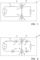
- FIG. 1 is a block diagram schematically illustrating a capacitive driving system 1, comprising a supply device 10 and a separate load device 20.
- the supply device 10 comprises two plate-shaped transmission electrodes 11, 12, which can be considered as output terminals.
- the supply device 10 further comprises a power generator 13 for generating AC power.
- a first output terminal 14 of the supply device 10 is connected to a first one 11 of the transmission electrodes, while a second output terminal 15 of the supply device 10 is connected to a second one 12 of the transmission electrodes.
- At least one inductor 16 is connected in series between the supply device 10 and the transmission electrodes 11, 12.
- the load device 20 comprises at least one load member 23 connected in series in between a first plate-shaped receiver electrode 21 and a second plate-shaped receiver electrode 22.
- the load member 23 is depicted as a resistor, and may ideally have ohmic characteristics.
- the transmission electrodes 11, 12 are located close to an outer surface of the supply device 10, and the receiver electrodes 21, 22 are located close to an outer surface of the load device 20.
- the disposition of the receiver electrodes 21, 22 matches the disposition of the transmission electrodes 11, 12, so that the load device 20 and the supply device 10 can be placed in close proximity of each other in an energy transfer position in which the first transmission electrode 11 together with the first receiver electrode 21 defines a first transfer capacitor 31 while simultaneously the second transmission electrode 12 together with the second receiver electrode 22 defines a second transfer capacitor 32.
- the inductor 16 together with the capacitors 31 and 32 define a resonance circuit having a resonance frequency, and the power generator 13 is designed to generate an AC output signal at said resonance frequency, so that the circuit operates in resonance and power is efficiently transferred from the power generator 13 to the load member 23.
- US 2009/302690 A1 discloses a power transmission system that includes a power supplying apparatus and a power receiving apparatus.
- the power supplying apparatus comprises a power generator, a first resonance unit and power supplying electrodes.
- the first resonance unit comprises an induction component and/or a capacitance component and resonates the power signal, which resonated power signal is externally radiated by the power supplying electrodes.
- the power receiving apparatus comprises power receiving electrodes for receiving the radiated power signal and a second resonance unit that has an induction component and/or a capacitance component.
- the power supplying electrodes and the power receiving electrodes define transfer capacitors.
- the control unit controls the induction component and/or a capacitance component of the first or the second resonance unit based on the power value measured by the power measurement unit. This is a rather complicated way to compensate for spatial or placement deviations.
- a general objective of the present invention is to eliminate or at least reduce the above-mentioned problems.
- At least one auxiliary capacitance is included in series with the transfer capacitors, either included in the supply device or in the load device, or both.
- the auxiliary capacitance is preferably designed to have a lower capacitance value than the optimum design capacitance of the transfer capacitors, and is preferably manufactured to a precision better than the expected variation of the transfer capacitors. Consequently, the resonance properties of the system are primarily determined by the auxiliary capacitance, so that the accuracy of the system as a whole has improved.
- FIG. 2 is a block diagram comparable to figure 1 , of a capacitive driving system 100 illustrating the basic principle underlying the present invention.
- the figure shows four possible locations for an auxiliary capacitance included in series with the transfer capacitors 31, 32.
- a first auxiliary capacitance 111 is shown at a first possible location in the supply device 10, in series with the first transmission electrode 11 and the inductor 16.
- a second auxiliary capacitance 112 is shown at a second possible location in the supply device 10, in series with the generator's opposite output 15 and the second transmission electrode 12.
- a third auxiliary capacitance 121 is shown at a first possible location in the load device 20, in between the load 23 and the first receiver electrode 21.
- a fourth auxiliary capacitance 122 is shown at a second possible location in the load device 20, in between the load 23 and the second receiver electrode 22. It should be clear that, in each and every one of the above examples, in the resonant circuit going from the first output terminal 14 of the supply device 10 to the opposite output terminal.
- the auxiliary capacitance concerned is arranged in series with the transfer capacitances.
- the invention can be implemented with any one of the auxiliary capacitances shown, but it is also possible to have a combination with two (or more) auxiliary capacitances in the supply device 10, two (or more) auxiliary capacitances in the load device 20, at one side or at opposite sides of the load, or one (or more) auxiliary capacitances in the supply device 10 and one (or more) auxiliary capacitances in the load device 20.
- the transfer capacitors 31, 32 each have a design capacitance C1 and a variation ⁇ 1, meaning that this capacitance can range from (1- ⁇ 1) ⁇ C1 to (1+ ⁇ 1) ⁇ C1.
- one auxiliary capacitance 121 in series with the load having a design capacitance Ca and a variation ⁇ a.
- Ca / C 1 x , with x ⁇ 1.
- ⁇ a / ⁇ 1 y , with y ⁇ 1.
- FIG 3 is a block diagram of a capacitive driving system 300 adapted for driving multiple loads.
- the supply device now indicated by reference numeral 310, has multiple sets of transmission electrodes 311, 312. In Figure 3 , four such sets are shown, but the number of sets may be higher or lower than four.
- Each set of electrodes is capable of coupling to a load device 320, always comprising a load member 323 in series with receiver electrodes 321, 322.
- FIG 3 only three load devices are shown. In the following, if it is intended to distinguish individual load devices and corresponding electrodes, characters A, B, C etc. will be added to the reference numerals.
- the supply device 310 can accommodate any number of load devices up to a certain maximum number. It is not necessary that all transmission electrodes are occupied. In figure 3 , transmission electrodes 311B, 312B are free.
- respective auxiliary capacitances 340 are arranged in series with the respective transmission electrodes 311. It is noted that such auxiliary capacitances 350 may, additionally or alternatively, also be arranged in series with the respective opposite transmission electrodes 312, as shown.
- auxiliary capacitances 340 and/or 350 are auxiliary capacitances dedicated to individual transmission electrodes.
- Figure 3 further shows that it is also possible to have, additionally or alternatively, one or more common auxiliary capacitances 361, 362 in series with one or more of the output terminals 14, 15 of the power generator 13.
- the various transmission electrodes are actually discrete electrodes: it is for instance possible that the transmission electrodes are implemented as continuous strips 411, 412, allowing one or more load devices, now indicated by reference numeral 420, to be coupled to any surface portion of such relatively large-surface electrode.
- Such system 400 is schematically illustrated in Figure 4 .
- the supply device 410 has one common auxiliary capacitance 461 in series with the inductance 16 and/or one common auxiliary capacitance 462 in series with the opposite output terminal 15 of the power generator 13.
- the auxiliary capacitance(s) is/are arranged in the supply device 310, 410.
- Such system 300, 400 is particularly useful in cases where one or more users can add one or more load devices as desired.
- Exemplary embodiments of such systems are: a charging system for mobile devices such as telephones, PDAs, laptops, etc; an illumination system where lamp units can be added and placed as desired.
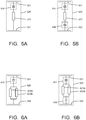
- FIG. 5A An example of such load device 520 according to the present invention is schematically illustrated in Figure 5A .
- the load device 520 comprises a load member 523 connected in series between two plate-shaped receiver electrodes 521, 522.
- a small auxiliary capacitance 540 is connected in series with the load 523.
- two such small auxiliary capacitances 541, 542 can be arranged at opposite sides of the load member 523, as shown in Figure 5B .
- This load device 520 can be used in cooperation with a supply device 10 of Figure 1 .
- FIG. 6A shows an embodiment of a load device 620 according to the present invention, comprising two loads 623A and 623B connected in parallel, this parallel circuit being connected in series between two plate-shaped receiver electrodes 621, 622.
- a small common auxiliary capacitance 640 is connected in series with the parallel arrangement of loads 623A and 623B.
- two such small auxiliary capacitances 641, 642 can be arranged in series at opposite sides of said parallel circuit of load members 623A, 623B, as shown in Figure 6B .
- said parallel circuit may comprise more than two load members connected in parallel, with always one or more common auxiliary capacitance(s) connected in series with the parallel circuit.
- FIG. 7 shows an embodiment of a load device 720 according to the present invention, comprising two load members 723A and 723B connected in parallel, this parallel circuit being connected in series between two plate-shaped receiver electrodes 721, 722.
- small dedicated auxiliary capacitances 741 and 742 are connected in series with the respective load members 723A and 723B.
- the load device may have more than two loads connected in parallel, each load provided with its own dedicated auxiliary capacitance in series.
- each load member may be connected in series to two auxiliary capacitances at opposite sides, but this is not shown for sake of simplicity.
- Figure 8 shows an embodiment of a load device 820 according to the present invention, where the load device is an illumination device and comprises a load 823 of two (or more) strings of LEDs connected in series between two plate-shaped receiver electrodes 821, 822, each string comprising one or more LEDs, and the two strings being arranged anti-parallel to each other.
- the strings have one common auxiliary capacitance 840, but it is also possible to have individual dedicated auxiliary capacitance per LED string, comparable to Figure 7 .
- an accurate capacitance for the purposes of the present invention, it is useful to turn to semiconductor technology.
- Methods for manufacturing a capacitance in an integrated circuit are known per se. This is particularly useful in case the load device is an illumination device and comprises a plurality of LEDs. These LEDs may be manufactured in one semiconductor chip that also comprises individual capacitances per LED ( Figure 7 ) and/or common capacitances, in series with the LEDs.
- FIG. 9 is a block diagram schematically illustrating such building component 900.
- This building component 900 comprises, formed in one common semiconductor substrate 901, an anti-parallel arrangement of two LEDs 923, or a multiplicity thereof.
- the building component 900 comprises at least one common capacitance in series with said anti-parallel arrangement of LEDs.
- the arrangement is symmetrical and comprises two common capacitances 941, 942 at opposite sides of the said parallel arrangement of LEDs. It is also possible to have individual memori-capacitances per LED.
- a capacitive driving system that comprises:
- Either the supply device or the load device, or both comprise at least one inductor connected in series with at least one of said respective electrodes.
- the supply device and the load device have an energy transfer position in which a first one of said transmission electrodes together with a first one of said receiver electrodes defines a first transfer capacitor while simultaneously a second one of said transmission electrodes together with a second one of said receiver electrodes defines a second transfer capacitor.
- At least one auxiliary capacitance is connected in series with the inductor and the load member.
- the supply device comprises two or even more inductors, it is possible that the inductor is or multiple inductors are located in the load device, and it is possible that one or more inductor(s) is/are located in the supply device while simultaneously one or more inductor(s) is/are located in the load device.
- the key of the invention is the presence of at least one series capacitance in either the supply device or the load device, or both, the present invention also relates to a supply device comprising at least one series capacitance but not necessarily comprising an inductor, and the present invention also relates to a load device comprising at least one series capacitance but not necessarily comprising an inductor.
- an illumination load device comprises two LEDs (or LED strings) arranged anti-parallel.
- Such anti-parallel arrangement allows for either polarity of the resonant current to flow through one of the two branches.
- the other of said paths does not need to include any LEDs, but may for instance include one or more normal (i.e.
- the device as a whole remains an illumination device, albeit perhaps with less illumination efficiency.
- the second path may even be provided by an internal breakdown voltage of the LED itself, or by an internal protection diode of the LED itself.
Claims (12)
- System (100) zur kapazitiven Ansteuerung, umfassend:- eine Versorgungseinrichtung (10), wobei die Versorgungseinrichtung (10) einen Energiegenerator (13) mit zwei Ausgangsanschlüssen (14, 15) sowie mindestens einem Satz kapazitiver Übertragungselektroden (11, 12), die mit jeweiligen der Ausgangsanschlüsse (14, 15) gekoppelt sind;- mindestens eine Lastvorrichtung (20), wobei die Lastvorrichtung (20) zwei kapazitive Empfängerelektroden (21, 22) und mindestens ein mit den Empfängerelektroden (21, 22) gekoppeltes Lastelement (23) umfasst;wobei zumindest die Versorgungseinrichtung (10) oder die Lastvorrichtung (20) min-destens einen Induktor (16) umfasst, der in Reihe mit mindestens einer der jeweiligen Elektroden (11, 12; 21, 22) geschaltet ist;
wobei die Versorgungseinrichtung (10) und die Lastvorrichtung (20) eine Energieübertragungsposition aufweisen, in der eine erste der Übertragungselektroden (11) zusammen mit einer ersten der Empfängerelektroden (21) einen ersten Übertragungskondensator (31) definiert, während gleichzeitig eine zweite der Übertragungselektroden (12) zusammen mit einer zweiten der Empfängerelektroden (22) einen zweiten Übertragungskondensator (32) definiert;
wobei in der Energieübertragungsposition eine Resonanzenergieübertragung von der Versorgungseinrichtung (10) zu dem Lastelement (23) stattfindet;
wobei in dem Resonanzkreis, der den mindestens einen Induktor (16) und das Lastelement (23) in der Energieübertragungsposition enthält, mindestens eine Hilfskapazität (111; 112; 121; 122) in Reihe mit dem Induktor (16) und dem Lastelement (23) geschaltet ist;
wobei der Kapazitätswert von jedem der Übertragungskondensatoren (31, 32) in einem Bereich von (1-Δ1)·C1 bis (1+Δ1)·C1 liegt, wobei C1 als Design-Kapazität der Übertragungskondensatoren angegeben ist, und wobei Δ1 als Variation der Übertragungskondensatoren angegeben ist;
wobei der Kapazitätswert der Hilfskapazität in einem Bereich von (1-Δa)·Ca bis (1+Δa)·Ca liegt, wobei Ca als Design-Kapazität der Hilfskapazität angegeben ist, und wobei Δa als Variation der Hilfskapazität angegeben ist;
und wobei Ca < C1 gilt und wobei Δa < Δ1 gilt. - System zur kapazitiven Ansteuerung nach Anspruch 1, wobei die Versorgungseinrichtung (10) mindestens einen Induktor (16) umfasst, der zwischen dem Energiegenerator (13) und mindestens einer der Übertragungselektroden (11, 12) in Reihe geschaltet ist.
- Einrichtung (10) zur kapazitiven Versorgung, die für ein System zur kapazitiven Ansteuerung nach Anspruch 1 eingerichtet ist, umfassend einen Energiegenerator (13) mit zwei Ausgangsanschlüssen (14, 15), mindestens einen Satz kapazitiver Übertragungselektroden (11, 12), die mit jeweiligen der Ausgangsanschlüsse (14, 15) gekoppelt sind, sowie mindestens eine Hilfskapazität (111; 112), die in Reihe mit mindestens einer der Übertragungselektroden (11, 12) geschaltet ist;
wobei die Übertragungselektroden (11, 12) zur kapazitiven Kopplung mit zwei kapazitiven Empfängerelektroden (21, 22) einer für ein System zur kapazitiven Ansteuerung nach Anspruch 1 eingerichteten Lastvorrichtung (20) ausgeführt und geeignet sind, wobei die gekoppelten Übertragungs- und Empfängerelektroden Übertragungskondensatoren definieren;
wobei die Versorgungseinrichtung (10) weiterhin mindestens einen Induktor (16) umfasst, der zwischen dem Energiegenerator (13) und mindestens einer der Übertragungselektroden (11, 12) in Reihe geschaltet ist;
wobei der Kapazitätswert von jedem der Übertragungskondensatoren in einem Bereich von (1-Δ1)·C1 bis (1+Δ1)·C1 liegt, wobei C1 als Design-Kapazität der Übertragungskondensatoren angegeben ist, und wobei Δ1 als Variation der Übertragungskondensatoren angegeben ist;
wobei der Kapazitätswert der Hilfskapazität in einem Bereich von (1-Δa)·Ca bis (1+Δa)·Ca liegt, wobei Ca als Design-Kapazität der Hilfskapazität angegeben ist, und wobei Δa als Variation der Hilfskapazität angegeben ist;
und wobei Ca < C1 gilt und wobei Δa < Δ1 gilt. - Einrichtung (310) zur kapazitiven Versorgung nach Anspruch 3, umfassend mehrere mit den Ausgangsanschlüssen (14, 15) gekoppelte kapazitive Übertragungselektroden (311, 312), weiterhin umfassend jeweilige Hilfskapazitäten (340; 350), die mit den jeweiligen Übertragungselektroden (311, 312) in Reihe geschaltet sind.
- Einrichtung (410) zur kapazitiven Versorgung nach Anspruch 3, umfassend mindestens zwei mit den Ausgangsanschlüssen (14, 15) gekoppelte, relative große kapazitive Übertragungselektroden (411, 412), die zur kapazitiven Kopplung mit kapazitiven Empfängerelektroden (421, 422) von mehreren Lastvorrichtungen (420) ausgeführt und geeignet sind, die weiterhin jeweils mindestens ein mit den Empfängerelektroden (421, 422) gekoppeltes Lastelement (423) umfassen;
wobei die Versorgungseinrichtung (410) weiterhin mindestens eine Hilfskapazität (461; 462) umfasst, die mit einer jeweiligen Übertragungselektrode (411, 412) in Reihe geschaltet ist. - Kapazitivlastvorrichtung (20), die für ein System zur kapazitiven Ansteuerung nach Anspruch 1 eingerichtet ist, umfassend zwei kapazitive Empfängerelektroden (21, 22), mindestens ein mit den Empfängerelektroden (21, 22) gekoppeltes Lastelement (23) sowie mindestens eine Hilfskapazität (121; 122), die in Reihe mit dem Lastelement (23) geschaltet ist und/oder in Reihe mit mindestens einer der Empfängerelektroden (21, 22) in Reihe geschaltet ist;
wobei die Empfängerelektroden (21, 22) zur kapazitiven Kopplung mit zwei kapazitiven Übertragungselektroden (11, 12) einer Versorgungseinrichtung (10) ausgeführt und geeignet sind, die für das System zur kapazitiven Ansteuerung nach Anspruch 1 eingerichtet ist, wobei die gekoppelten Übertragungs- und Empfängerelektroden Übertragungskondensatoren definieren, und vorzugsweise mindestens einen Induktor (16) umfasst, der zwischen dem Energiegenerator (13) und mindestens einer der Übertragungselektroden (11, 12) in Reihe geschaltet ist,
wobei der Kapazitätswert von jedem der Übertragungskondensatoren in einem Bereich von (1-Δ1)·C1 bis (1+Δ1)·C1 liegt, wobei C1 als Design-Kapazität der Übertragungskondensatoren angegeben ist, und wobei Δ1 als Variation der Übertragungskondensatoren angegeben ist;
wobei der Kapazitätswert der Hilfskapazität in einem Bereich von (1-Δa)·Ca bis (1+Δa)·Ca liegt, wobei Ca als Design-Kapazität der Hilfskapazität angegeben ist, und wobei Δa als Variation der Hilfskapazität angegeben ist;
und wobei Ca < C1 gilt und wobei Δa < Δ1 gilt. - Kapazitivlastvorrichtung (520) nach Anspruch 6, umfassend zwei Hilfskapazitäten (541; 542), die an gegenüberliegenden Enden des Lastelements (23) in Reihe geschaltet sind.
- Kapazitivlastvorrichtung (620) nach Anspruch 6, umfassend eine Parallelanordnung von mindestens zwei Lastelementen (623A, 623B) und eine mit der Parallelanordnung in Reihe geschaltete, gemeinsame Hilfskapazität (640).
- Kapazitivlastvorrichtung (620) nach Anspruch 6, umfassend eine Parallelanordnung von mindestens zwei Lastelementen (623A, 623B) und zwei Hilfskapazitäten (641; 642), die an gegenüberliegenden Enden der Parallelanordnung in Reihe geschaltet sind.
- Kapazitivlastvorrichtung (720) nach Anspruch 6, umfassend eine Parallelanordnung von mindestens zwei Lastelementen (723A, 723B) und jeweilige einzelne Hilfskapazitäten (741; 742), die mit jeweiligen der Lastelemente in Reihe geschaltet sind.
- Kapazitivlastvorrichtung (820) nach einem der Ansprüche 8-10, wobei die Lastvorrichtung eine Beleuchtungslastvorrichtung ist und mindestens eines der zwei Lastelemente einen String aus mindestens einer ersten LED umfasst, während das andere der zwei Lastelemente zumindest in der entgegengesetzten Richtung gegenüber der Vorwärtsrichtung der mindestens einen ersten LED elektrisch leitend ist, wobei das andere der zwei Lastelemente vorzugsweise einen String aus mindestens einer LED umfasst, die antiparallel zu der mindestens einen ersten LED angeordnet ist.
- Halbleiterbauteil (900), das für ein System zur kapazitiven Ansteuerung nach Anspruch 1 eingerichtet ist, umfassend ein gemeinsames Halbleitersubstrat (901), mindestens eine Antiparallel-Anordnung von Strings aus einer oder mehreren in dem Halbleitersubstrat (901) ausgebildeten LEDs (923) sowie mindestens eine Hilfskapazität (941, 942), die in dem Halbleitersubstrat (901) ausgebildet und in Reihe mit der Antiparallelanordnung von LEDs geschaltet ist oder in Reihe mit jeweiligen der LED-Strings in Reihe geschaltet ist.
Priority Applications (1)
| Application Number | Priority Date | Filing Date | Title |
|---|---|---|---|
| EP14781566.6A EP3055918B1 (de) | 2013-10-09 | 2014-10-09 | System zum kapazitativen antreiben einer last |
Applications Claiming Priority (3)
| Application Number | Priority Date | Filing Date | Title |
|---|---|---|---|
| EP13187953 | 2013-10-09 | ||
| EP14781566.6A EP3055918B1 (de) | 2013-10-09 | 2014-10-09 | System zum kapazitativen antreiben einer last |
| PCT/EP2014/071591 WO2015052263A1 (en) | 2013-10-09 | 2014-10-09 | System for capacitively driving a load |
Publications (2)
| Publication Number | Publication Date |
|---|---|
| EP3055918A1 EP3055918A1 (de) | 2016-08-17 |
| EP3055918B1 true EP3055918B1 (de) | 2017-04-26 |
Family
ID=49484082
Family Applications (1)
| Application Number | Title | Priority Date | Filing Date |
|---|---|---|---|
| EP14781566.6A Not-in-force EP3055918B1 (de) | 2013-10-09 | 2014-10-09 | System zum kapazitativen antreiben einer last |
Country Status (5)
| Country | Link |
|---|---|
| US (1) | US9748801B2 (de) |
| EP (1) | EP3055918B1 (de) |
| JP (1) | JP2016538810A (de) |
| CN (1) | CN105637731A (de) |
| WO (1) | WO2015052263A1 (de) |
Families Citing this family (5)
| Publication number | Priority date | Publication date | Assignee | Title |
|---|---|---|---|---|
| CN105191061B (zh) * | 2013-03-19 | 2017-11-14 | 株式会社村田制作所 | 无线电力传输系统 |
| WO2015118945A1 (ja) * | 2014-02-07 | 2015-08-13 | 株式会社村田製作所 | 電力伝送システム |
| DE102016105897A1 (de) * | 2016-03-31 | 2017-10-05 | Technische Universität Darmstadt | Vorrichtung und Verfahren zum Aufprägen eines elektrischen Stromes |
| CN108964289B (zh) * | 2018-07-23 | 2020-03-31 | 重庆大学 | 具有双t型谐振网络的ecpt系统及其参数设计方法 |
| DE102019120428A1 (de) | 2019-07-29 | 2021-02-04 | Bayerische Motoren Werke Aktiengesellschaft | Energieübertragungsvorrichtung zum drahtlosen Übertragen von elektrischer Energie, sowie Verfahren |
Family Cites Families (18)
| Publication number | Priority date | Publication date | Assignee | Title |
|---|---|---|---|---|
| US3273046A (en) * | 1961-05-08 | 1966-09-13 | Gen Electric | Inverter circuits with independent commutation circuits |
| WO2002031406A1 (en) * | 2000-10-13 | 2002-04-18 | Flat White Lighting Pty Ltd | Lighting system |
| JP2003345308A (ja) * | 2002-05-29 | 2003-12-03 | Pioneer Electronic Corp | 表示パネル及び表示装置 |
| US7049754B2 (en) | 2004-07-06 | 2006-05-23 | Dell Products L.P. | System and method for reducing information handling system distributed capacitance |
| FR2876516A1 (fr) * | 2004-10-11 | 2006-04-14 | Thomson Licensing Sa | Amplificateur destine a generer un signal de tension rectangulaire a commutations douces sur une charge capacitive |
| JP4557049B2 (ja) * | 2008-06-09 | 2010-10-06 | ソニー株式会社 | 伝送システム、給電装置、受電装置、及び伝送方法 |
| RU2499331C2 (ru) | 2008-06-17 | 2013-11-20 | Конинклейке Филипс Электроникс Н.В. | Светоизлучающее устройство, выполненное с возможностью приведения в действие переменным током |
| US20120091819A1 (en) | 2008-09-27 | 2012-04-19 | Konrad Kulikowski | Computer that wirelessly powers accessories |
| EP2579426B1 (de) | 2010-05-28 | 2019-03-27 | Murata Manufacturing Co., Ltd. | Kraftübertragungssystem |
| JP5093386B2 (ja) * | 2010-08-25 | 2012-12-12 | 株式会社村田製作所 | 送電装置および電力伝送システム |
| US8994223B2 (en) * | 2010-11-08 | 2015-03-31 | R2Z Innovations Inc. | Systems and methods for self powered electronic devices |
| JP6019045B2 (ja) * | 2011-03-07 | 2016-11-02 | コーニンクレッカ フィリップス エヌ ヴェKoninklijke Philips N.V. | エレクトロルミネセント装置 |
| US8970069B2 (en) | 2011-03-28 | 2015-03-03 | Tdk Corporation | Wireless power receiver and wireless power transmission system |
| EP2745417B1 (de) * | 2011-08-16 | 2019-06-19 | Signify Holding B.V. | Transparentes und kapazitives system für drahtlose stromeinspeisung |
| US9438129B2 (en) * | 2011-10-06 | 2016-09-06 | Cesar Ladron de Guevara | Input/output power and signal transfer isolator device |
| CN102508950B (zh) * | 2011-10-14 | 2013-12-11 | 广东电网公司电力科学研究院 | 地区调度自动化系统及其与远程监测诊断中心通信的方法 |
| JP2013158196A (ja) * | 2012-01-31 | 2013-08-15 | Kyushu Univ | 伝送システム及び受電装置 |
| JP2014135880A (ja) * | 2013-01-11 | 2014-07-24 | Kyushu Univ | 伝送システム、送電装置、受電装置及び伝送方法 |
-
2014
- 2014-10-09 EP EP14781566.6A patent/EP3055918B1/de not_active Not-in-force
- 2014-10-09 CN CN201480055694.7A patent/CN105637731A/zh active Pending
- 2014-10-09 JP JP2016520638A patent/JP2016538810A/ja not_active Ceased
- 2014-10-09 WO PCT/EP2014/071591 patent/WO2015052263A1/en active Application Filing
- 2014-10-09 US US15/027,693 patent/US9748801B2/en not_active Expired - Fee Related
Non-Patent Citations (1)
| Title |
|---|
| None * |
Also Published As
| Publication number | Publication date |
|---|---|
| US9748801B2 (en) | 2017-08-29 |
| JP2016538810A (ja) | 2016-12-08 |
| WO2015052263A1 (en) | 2015-04-16 |
| CN105637731A (zh) | 2016-06-01 |
| US20160248274A1 (en) | 2016-08-25 |
| EP3055918A1 (de) | 2016-08-17 |
Similar Documents
| Publication | Publication Date | Title |
|---|---|---|
| EP3055918B1 (de) | System zum kapazitativen antreiben einer last | |
| EP2745379B1 (de) | Kapazitives kontaktloses energieversorgungssystem | |
| US11962163B2 (en) | Power transmission device and wireless power transmission system | |
| CN106410991B (zh) | 异物检测装置、无线送电装置以及无线电力传输系统 | |
| CN102680125B (zh) | 无线温度传感器 | |
| US9698629B2 (en) | Wireless power transmission system, power transmitting device, and power receiving device | |
| JP2012186472A (ja) | 給電装置及び受給電装置 | |
| US9831710B2 (en) | Electric power transmitting apparatus and method for controlling electric power transmission | |
| US10084342B2 (en) | Transfer layer for wireless capacitive power | |
| EP2824678A1 (de) | Energieversorgungsvorrichtung, energieempfangsvorrichtung und energieversorgungs-/-empfangsvorrichtung | |
| CN104254960A (zh) | 无线电力接收器及其电力控制方法 | |
| US10033217B2 (en) | Wireless power receiver device, wireless power transmitter device, and wireless power transceiver device | |
| CN101854070A (zh) | 电池充电器 | |
| KR20160030672A (ko) | 무선 전력 수신 장치 및 무선 전력 송수신 시스템 | |
| US20100317233A1 (en) | Electrical connection system | |
| US9673658B2 (en) | Non-contact capacitive coupling type power charging apparatus and non-contact capacitive coupling type battery apparatus | |
| US9899138B1 (en) | Coil structure for generating a uniform magnetic field and coil apparatus having the same | |
| KR20120008632A (ko) | 패키징 칩에 의한 무접점 배터리 장치 및 충전 시스템 | |
| US20150215007A1 (en) | Wireless power transmission system | |
| KR20110126428A (ko) | 발광 소자 | |
| KR101229909B1 (ko) | 피씨비 일체형 무접점 배터리 장치 및 충전 시스템 | |
| WO2015052003A1 (en) | Wireless capacitive power receiving module | |
| JP2017028780A (ja) | ワイヤレス伝送装置 |
Legal Events
| Date | Code | Title | Description |
|---|---|---|---|
| PUAI | Public reference made under article 153(3) epc to a published international application that has entered the european phase |
Free format text: ORIGINAL CODE: 0009012 |
|
| 17P | Request for examination filed |
Effective date: 20160509 |
|
| AK | Designated contracting states |
Kind code of ref document: A1 Designated state(s): AL AT BE BG CH CY CZ DE DK EE ES FI FR GB GR HR HU IE IS IT LI LT LU LV MC MK MT NL NO PL PT RO RS SE SI SK SM TR |
|
| AX | Request for extension of the european patent |
Extension state: BA ME |
|
| REG | Reference to a national code |
Ref country code: DE Ref legal event code: R079 Ref document number: 602014009122 Country of ref document: DE Free format text: PREVIOUS MAIN CLASS: H02J0005000000 Ipc: H02J0050050000 |
|
| RIC1 | Information provided on ipc code assigned before grant |
Ipc: H02J 50/05 20160101AFI20161013BHEP |
|
| GRAP | Despatch of communication of intention to grant a patent |
Free format text: ORIGINAL CODE: EPIDOSNIGR1 |
|
| INTG | Intention to grant announced |
Effective date: 20161129 |
|
| DAX | Request for extension of the european patent (deleted) | ||
| GRAS | Grant fee paid |
Free format text: ORIGINAL CODE: EPIDOSNIGR3 |
|
| GRAA | (expected) grant |
Free format text: ORIGINAL CODE: 0009210 |
|
| AK | Designated contracting states |
Kind code of ref document: B1 Designated state(s): AL AT BE BG CH CY CZ DE DK EE ES FI FR GB GR HR HU IE IS IT LI LT LU LV MC MK MT NL NO PL PT RO RS SE SI SK SM TR |
|
| REG | Reference to a national code |
Ref country code: GB Ref legal event code: FG4D |
|
| REG | Reference to a national code |
Ref country code: CH Ref legal event code: EP |
|
| REG | Reference to a national code |
Ref country code: AT Ref legal event code: REF Ref document number: 888644 Country of ref document: AT Kind code of ref document: T Effective date: 20170515 |
|
| REG | Reference to a national code |
Ref country code: IE Ref legal event code: FG4D |
|
| REG | Reference to a national code |
Ref country code: DE Ref legal event code: R096 Ref document number: 602014009122 Country of ref document: DE |
|
| RIN2 | Information on inventor provided after grant (corrected) |
Inventor name: SEMPEL, ADRIANUS Inventor name: VAN DEN BIGGELAAR, THEODORUS JOHANNES PETRUS |
|
| REG | Reference to a national code |
Ref country code: NL Ref legal event code: MP Effective date: 20170426 |
|
| REG | Reference to a national code |
Ref country code: LT Ref legal event code: MG4D |
|
| REG | Reference to a national code |
Ref country code: AT Ref legal event code: MK05 Ref document number: 888644 Country of ref document: AT Kind code of ref document: T Effective date: 20170426 |
|
| PG25 | Lapsed in a contracting state [announced via postgrant information from national office to epo] |
Ref country code: NL Free format text: LAPSE BECAUSE OF FAILURE TO SUBMIT A TRANSLATION OF THE DESCRIPTION OR TO PAY THE FEE WITHIN THE PRESCRIBED TIME-LIMIT Effective date: 20170426 |
|
| PG25 | Lapsed in a contracting state [announced via postgrant information from national office to epo] |
Ref country code: AT Free format text: LAPSE BECAUSE OF FAILURE TO SUBMIT A TRANSLATION OF THE DESCRIPTION OR TO PAY THE FEE WITHIN THE PRESCRIBED TIME-LIMIT Effective date: 20170426 Ref country code: GR Free format text: LAPSE BECAUSE OF FAILURE TO SUBMIT A TRANSLATION OF THE DESCRIPTION OR TO PAY THE FEE WITHIN THE PRESCRIBED TIME-LIMIT Effective date: 20170727 Ref country code: LT Free format text: LAPSE BECAUSE OF FAILURE TO SUBMIT A TRANSLATION OF THE DESCRIPTION OR TO PAY THE FEE WITHIN THE PRESCRIBED TIME-LIMIT Effective date: 20170426 Ref country code: ES Free format text: LAPSE BECAUSE OF FAILURE TO SUBMIT A TRANSLATION OF THE DESCRIPTION OR TO PAY THE FEE WITHIN THE PRESCRIBED TIME-LIMIT Effective date: 20170426 Ref country code: FI Free format text: LAPSE BECAUSE OF FAILURE TO SUBMIT A TRANSLATION OF THE DESCRIPTION OR TO PAY THE FEE WITHIN THE PRESCRIBED TIME-LIMIT Effective date: 20170426 Ref country code: NO Free format text: LAPSE BECAUSE OF FAILURE TO SUBMIT A TRANSLATION OF THE DESCRIPTION OR TO PAY THE FEE WITHIN THE PRESCRIBED TIME-LIMIT Effective date: 20170726 Ref country code: HR Free format text: LAPSE BECAUSE OF FAILURE TO SUBMIT A TRANSLATION OF THE DESCRIPTION OR TO PAY THE FEE WITHIN THE PRESCRIBED TIME-LIMIT Effective date: 20170426 |
|
| REG | Reference to a national code |
Ref country code: FR Ref legal event code: PLFP Year of fee payment: 4 |
|
| PG25 | Lapsed in a contracting state [announced via postgrant information from national office to epo] |
Ref country code: BG Free format text: LAPSE BECAUSE OF FAILURE TO SUBMIT A TRANSLATION OF THE DESCRIPTION OR TO PAY THE FEE WITHIN THE PRESCRIBED TIME-LIMIT Effective date: 20170726 Ref country code: LV Free format text: LAPSE BECAUSE OF FAILURE TO SUBMIT A TRANSLATION OF THE DESCRIPTION OR TO PAY THE FEE WITHIN THE PRESCRIBED TIME-LIMIT Effective date: 20170426 Ref country code: PL Free format text: LAPSE BECAUSE OF FAILURE TO SUBMIT A TRANSLATION OF THE DESCRIPTION OR TO PAY THE FEE WITHIN THE PRESCRIBED TIME-LIMIT Effective date: 20170426 Ref country code: RS Free format text: LAPSE BECAUSE OF FAILURE TO SUBMIT A TRANSLATION OF THE DESCRIPTION OR TO PAY THE FEE WITHIN THE PRESCRIBED TIME-LIMIT Effective date: 20170426 Ref country code: IS Free format text: LAPSE BECAUSE OF FAILURE TO SUBMIT A TRANSLATION OF THE DESCRIPTION OR TO PAY THE FEE WITHIN THE PRESCRIBED TIME-LIMIT Effective date: 20170826 Ref country code: SE Free format text: LAPSE BECAUSE OF FAILURE TO SUBMIT A TRANSLATION OF THE DESCRIPTION OR TO PAY THE FEE WITHIN THE PRESCRIBED TIME-LIMIT Effective date: 20170426 |
|
| REG | Reference to a national code |
Ref country code: DE Ref legal event code: R097 Ref document number: 602014009122 Country of ref document: DE |
|
| PG25 | Lapsed in a contracting state [announced via postgrant information from national office to epo] |
Ref country code: SK Free format text: LAPSE BECAUSE OF FAILURE TO SUBMIT A TRANSLATION OF THE DESCRIPTION OR TO PAY THE FEE WITHIN THE PRESCRIBED TIME-LIMIT Effective date: 20170426 Ref country code: RO Free format text: LAPSE BECAUSE OF FAILURE TO SUBMIT A TRANSLATION OF THE DESCRIPTION OR TO PAY THE FEE WITHIN THE PRESCRIBED TIME-LIMIT Effective date: 20170426 Ref country code: DK Free format text: LAPSE BECAUSE OF FAILURE TO SUBMIT A TRANSLATION OF THE DESCRIPTION OR TO PAY THE FEE WITHIN THE PRESCRIBED TIME-LIMIT Effective date: 20170426 Ref country code: CZ Free format text: LAPSE BECAUSE OF FAILURE TO SUBMIT A TRANSLATION OF THE DESCRIPTION OR TO PAY THE FEE WITHIN THE PRESCRIBED TIME-LIMIT Effective date: 20170426 Ref country code: EE Free format text: LAPSE BECAUSE OF FAILURE TO SUBMIT A TRANSLATION OF THE DESCRIPTION OR TO PAY THE FEE WITHIN THE PRESCRIBED TIME-LIMIT Effective date: 20170426 |
|
| PGFP | Annual fee paid to national office [announced via postgrant information from national office to epo] |
Ref country code: FR Payment date: 20171031 Year of fee payment: 4 |
|
| PG25 | Lapsed in a contracting state [announced via postgrant information from national office to epo] |
Ref country code: IT Free format text: LAPSE BECAUSE OF FAILURE TO SUBMIT A TRANSLATION OF THE DESCRIPTION OR TO PAY THE FEE WITHIN THE PRESCRIBED TIME-LIMIT Effective date: 20170426 Ref country code: SM Free format text: LAPSE BECAUSE OF FAILURE TO SUBMIT A TRANSLATION OF THE DESCRIPTION OR TO PAY THE FEE WITHIN THE PRESCRIBED TIME-LIMIT Effective date: 20170426 |
|
| PLBE | No opposition filed within time limit |
Free format text: ORIGINAL CODE: 0009261 |
|
| STAA | Information on the status of an ep patent application or granted ep patent |
Free format text: STATUS: NO OPPOSITION FILED WITHIN TIME LIMIT |
|
| 26N | No opposition filed |
Effective date: 20180129 |
|
| PGFP | Annual fee paid to national office [announced via postgrant information from national office to epo] |
Ref country code: DE Payment date: 20171229 Year of fee payment: 4 |
|
| PG25 | Lapsed in a contracting state [announced via postgrant information from national office to epo] |
Ref country code: MC Free format text: LAPSE BECAUSE OF FAILURE TO SUBMIT A TRANSLATION OF THE DESCRIPTION OR TO PAY THE FEE WITHIN THE PRESCRIBED TIME-LIMIT Effective date: 20170426 |
|
| REG | Reference to a national code |
Ref country code: CH Ref legal event code: PL |
|
| REG | Reference to a national code |
Ref country code: IE Ref legal event code: MM4A |
|
| PG25 | Lapsed in a contracting state [announced via postgrant information from national office to epo] |
Ref country code: LU Free format text: LAPSE BECAUSE OF NON-PAYMENT OF DUE FEES Effective date: 20171009 Ref country code: LI Free format text: LAPSE BECAUSE OF NON-PAYMENT OF DUE FEES Effective date: 20171031 Ref country code: CH Free format text: LAPSE BECAUSE OF NON-PAYMENT OF DUE FEES Effective date: 20171031 |
|
| REG | Reference to a national code |
Ref country code: BE Ref legal event code: MM Effective date: 20171031 |
|
| PG25 | Lapsed in a contracting state [announced via postgrant information from national office to epo] |
Ref country code: BE Free format text: LAPSE BECAUSE OF NON-PAYMENT OF DUE FEES Effective date: 20171031 |
|
| PG25 | Lapsed in a contracting state [announced via postgrant information from national office to epo] |
Ref country code: MT Free format text: LAPSE BECAUSE OF NON-PAYMENT OF DUE FEES Effective date: 20171009 |
|
| PG25 | Lapsed in a contracting state [announced via postgrant information from national office to epo] |
Ref country code: IE Free format text: LAPSE BECAUSE OF NON-PAYMENT OF DUE FEES Effective date: 20171009 |
|
| REG | Reference to a national code |
Ref country code: DE Ref legal event code: R119 Ref document number: 602014009122 Country of ref document: DE |
|
| GBPC | Gb: european patent ceased through non-payment of renewal fee |
Effective date: 20181009 |
|
| PG25 | Lapsed in a contracting state [announced via postgrant information from national office to epo] |
Ref country code: HU Free format text: LAPSE BECAUSE OF FAILURE TO SUBMIT A TRANSLATION OF THE DESCRIPTION OR TO PAY THE FEE WITHIN THE PRESCRIBED TIME-LIMIT; INVALID AB INITIO Effective date: 20141009 |
|
| PG25 | Lapsed in a contracting state [announced via postgrant information from national office to epo] |
Ref country code: DE Free format text: LAPSE BECAUSE OF NON-PAYMENT OF DUE FEES Effective date: 20190501 |
|
| PG25 | Lapsed in a contracting state [announced via postgrant information from national office to epo] |
Ref country code: FR Free format text: LAPSE BECAUSE OF NON-PAYMENT OF DUE FEES Effective date: 20181031 |
|
| PG25 | Lapsed in a contracting state [announced via postgrant information from national office to epo] |
Ref country code: SI Free format text: LAPSE BECAUSE OF FAILURE TO SUBMIT A TRANSLATION OF THE DESCRIPTION OR TO PAY THE FEE WITHIN THE PRESCRIBED TIME-LIMIT Effective date: 20170426 |
|
| PG25 | Lapsed in a contracting state [announced via postgrant information from national office to epo] |
Ref country code: GB Free format text: LAPSE BECAUSE OF NON-PAYMENT OF DUE FEES Effective date: 20181009 Ref country code: CY Free format text: LAPSE BECAUSE OF FAILURE TO SUBMIT A TRANSLATION OF THE DESCRIPTION OR TO PAY THE FEE WITHIN THE PRESCRIBED TIME-LIMIT Effective date: 20170426 |
|
| PG25 | Lapsed in a contracting state [announced via postgrant information from national office to epo] |
Ref country code: MK Free format text: LAPSE BECAUSE OF FAILURE TO SUBMIT A TRANSLATION OF THE DESCRIPTION OR TO PAY THE FEE WITHIN THE PRESCRIBED TIME-LIMIT Effective date: 20170426 |
|
| PG25 | Lapsed in a contracting state [announced via postgrant information from national office to epo] |
Ref country code: TR Free format text: LAPSE BECAUSE OF FAILURE TO SUBMIT A TRANSLATION OF THE DESCRIPTION OR TO PAY THE FEE WITHIN THE PRESCRIBED TIME-LIMIT Effective date: 20170426 |
|
| PG25 | Lapsed in a contracting state [announced via postgrant information from national office to epo] |
Ref country code: PT Free format text: LAPSE BECAUSE OF FAILURE TO SUBMIT A TRANSLATION OF THE DESCRIPTION OR TO PAY THE FEE WITHIN THE PRESCRIBED TIME-LIMIT Effective date: 20170426 |
|
| PG25 | Lapsed in a contracting state [announced via postgrant information from national office to epo] |
Ref country code: AL Free format text: LAPSE BECAUSE OF FAILURE TO SUBMIT A TRANSLATION OF THE DESCRIPTION OR TO PAY THE FEE WITHIN THE PRESCRIBED TIME-LIMIT Effective date: 20170426 |