EP3053543A1 - Device having a surface structure for driving into the human or animal body - Google Patents
Device having a surface structure for driving into the human or animal body Download PDFInfo
- Publication number
- EP3053543A1 EP3053543A1 EP15154319.6A EP15154319A EP3053543A1 EP 3053543 A1 EP3053543 A1 EP 3053543A1 EP 15154319 A EP15154319 A EP 15154319A EP 3053543 A1 EP3053543 A1 EP 3053543A1
- Authority
- EP
- European Patent Office
- Prior art keywords
- surface structure
- implant
- der
- static friction
- displacement direction
- Prior art date
- Legal status (The legal status is an assumption and is not a legal conclusion. Google has not performed a legal analysis and makes no representation as to the accuracy of the status listed.)
- Withdrawn
Links
Images


Classifications
-
- A—HUMAN NECESSITIES
- A61—MEDICAL OR VETERINARY SCIENCE; HYGIENE
- A61N—ELECTROTHERAPY; MAGNETOTHERAPY; RADIATION THERAPY; ULTRASOUND THERAPY
- A61N1/00—Electrotherapy; Circuits therefor
- A61N1/18—Applying electric currents by contact electrodes
- A61N1/32—Applying electric currents by contact electrodes alternating or intermittent currents
- A61N1/36—Applying electric currents by contact electrodes alternating or intermittent currents for stimulation
- A61N1/372—Arrangements in connection with the implantation of stimulators
- A61N1/375—Constructional arrangements, e.g. casings
-
- A—HUMAN NECESSITIES
- A61—MEDICAL OR VETERINARY SCIENCE; HYGIENE
- A61F—FILTERS IMPLANTABLE INTO BLOOD VESSELS; PROSTHESES; DEVICES PROVIDING PATENCY TO, OR PREVENTING COLLAPSING OF, TUBULAR STRUCTURES OF THE BODY, e.g. STENTS; ORTHOPAEDIC, NURSING OR CONTRACEPTIVE DEVICES; FOMENTATION; TREATMENT OR PROTECTION OF EYES OR EARS; BANDAGES, DRESSINGS OR ABSORBENT PADS; FIRST-AID KITS
- A61F2/00—Filters implantable into blood vessels; Prostheses, i.e. artificial substitutes or replacements for parts of the body; Appliances for connecting them with the body; Devices providing patency to, or preventing collapsing of, tubular structures of the body, e.g. stents
- A61F2/0077—Special surfaces of prostheses, e.g. for improving ingrowth
-
- A—HUMAN NECESSITIES
- A61—MEDICAL OR VETERINARY SCIENCE; HYGIENE
- A61N—ELECTROTHERAPY; MAGNETOTHERAPY; RADIATION THERAPY; ULTRASOUND THERAPY
- A61N1/00—Electrotherapy; Circuits therefor
- A61N1/02—Details
- A61N1/04—Electrodes
- A61N1/05—Electrodes for implantation or insertion into the body, e.g. heart electrode
- A61N1/0587—Epicardial electrode systems; Endocardial electrodes piercing the pericardium
- A61N1/059—Anchoring means
-
- A—HUMAN NECESSITIES
- A61—MEDICAL OR VETERINARY SCIENCE; HYGIENE
- A61N—ELECTROTHERAPY; MAGNETOTHERAPY; RADIATION THERAPY; ULTRASOUND THERAPY
- A61N1/00—Electrotherapy; Circuits therefor
- A61N1/18—Applying electric currents by contact electrodes
- A61N1/32—Applying electric currents by contact electrodes alternating or intermittent currents
- A61N1/36—Applying electric currents by contact electrodes alternating or intermittent currents for stimulation
- A61N1/372—Arrangements in connection with the implantation of stimulators
- A61N1/375—Constructional arrangements, e.g. casings
- A61N1/37512—Pacemakers
-
- A—HUMAN NECESSITIES
- A61—MEDICAL OR VETERINARY SCIENCE; HYGIENE
- A61N—ELECTROTHERAPY; MAGNETOTHERAPY; RADIATION THERAPY; ULTRASOUND THERAPY
- A61N1/00—Electrotherapy; Circuits therefor
- A61N1/18—Applying electric currents by contact electrodes
- A61N1/32—Applying electric currents by contact electrodes alternating or intermittent currents
- A61N1/36—Applying electric currents by contact electrodes alternating or intermittent currents for stimulation
- A61N1/372—Arrangements in connection with the implantation of stimulators
- A61N1/375—Constructional arrangements, e.g. casings
- A61N1/37518—Anchoring of the implants, e.g. fixation
-
- A—HUMAN NECESSITIES
- A61—MEDICAL OR VETERINARY SCIENCE; HYGIENE
- A61F—FILTERS IMPLANTABLE INTO BLOOD VESSELS; PROSTHESES; DEVICES PROVIDING PATENCY TO, OR PREVENTING COLLAPSING OF, TUBULAR STRUCTURES OF THE BODY, e.g. STENTS; ORTHOPAEDIC, NURSING OR CONTRACEPTIVE DEVICES; FOMENTATION; TREATMENT OR PROTECTION OF EYES OR EARS; BANDAGES, DRESSINGS OR ABSORBENT PADS; FIRST-AID KITS
- A61F2/00—Filters implantable into blood vessels; Prostheses, i.e. artificial substitutes or replacements for parts of the body; Appliances for connecting them with the body; Devices providing patency to, or preventing collapsing of, tubular structures of the body, e.g. stents
- A61F2/0077—Special surfaces of prostheses, e.g. for improving ingrowth
- A61F2002/0081—Special surfaces of prostheses, e.g. for improving ingrowth directly machined on the prosthetic surface, e.g. holes, grooves
-
- A—HUMAN NECESSITIES
- A61—MEDICAL OR VETERINARY SCIENCE; HYGIENE
- A61F—FILTERS IMPLANTABLE INTO BLOOD VESSELS; PROSTHESES; DEVICES PROVIDING PATENCY TO, OR PREVENTING COLLAPSING OF, TUBULAR STRUCTURES OF THE BODY, e.g. STENTS; ORTHOPAEDIC, NURSING OR CONTRACEPTIVE DEVICES; FOMENTATION; TREATMENT OR PROTECTION OF EYES OR EARS; BANDAGES, DRESSINGS OR ABSORBENT PADS; FIRST-AID KITS
- A61F2210/00—Particular material properties of prostheses classified in groups A61F2/00 - A61F2/26 or A61F2/82 or A61F9/00 or A61F11/00 or subgroups thereof
- A61F2210/0004—Particular material properties of prostheses classified in groups A61F2/00 - A61F2/26 or A61F2/82 or A61F9/00 or A61F11/00 or subgroups thereof bioabsorbable
-
- A—HUMAN NECESSITIES
- A61—MEDICAL OR VETERINARY SCIENCE; HYGIENE
- A61F—FILTERS IMPLANTABLE INTO BLOOD VESSELS; PROSTHESES; DEVICES PROVIDING PATENCY TO, OR PREVENTING COLLAPSING OF, TUBULAR STRUCTURES OF THE BODY, e.g. STENTS; ORTHOPAEDIC, NURSING OR CONTRACEPTIVE DEVICES; FOMENTATION; TREATMENT OR PROTECTION OF EYES OR EARS; BANDAGES, DRESSINGS OR ABSORBENT PADS; FIRST-AID KITS
- A61F2250/00—Special features of prostheses classified in groups A61F2/00 - A61F2/26 or A61F2/82 or A61F9/00 or A61F11/00 or subgroups thereof
- A61F2250/0004—Special features of prostheses classified in groups A61F2/00 - A61F2/26 or A61F2/82 or A61F9/00 or A61F11/00 or subgroups thereof adjustable
-
- A—HUMAN NECESSITIES
- A61—MEDICAL OR VETERINARY SCIENCE; HYGIENE
- A61F—FILTERS IMPLANTABLE INTO BLOOD VESSELS; PROSTHESES; DEVICES PROVIDING PATENCY TO, OR PREVENTING COLLAPSING OF, TUBULAR STRUCTURES OF THE BODY, e.g. STENTS; ORTHOPAEDIC, NURSING OR CONTRACEPTIVE DEVICES; FOMENTATION; TREATMENT OR PROTECTION OF EYES OR EARS; BANDAGES, DRESSINGS OR ABSORBENT PADS; FIRST-AID KITS
- A61F2250/00—Special features of prostheses classified in groups A61F2/00 - A61F2/26 or A61F2/82 or A61F9/00 or A61F11/00 or subgroups thereof
- A61F2250/0014—Special features of prostheses classified in groups A61F2/00 - A61F2/26 or A61F2/82 or A61F9/00 or A61F11/00 or subgroups thereof having different values of a given property or geometrical feature, e.g. mechanical property or material property, at different locations within the same prosthesis
- A61F2250/0021—Special features of prostheses classified in groups A61F2/00 - A61F2/26 or A61F2/82 or A61F9/00 or A61F11/00 or subgroups thereof having different values of a given property or geometrical feature, e.g. mechanical property or material property, at different locations within the same prosthesis differing in coefficient of friction
Abstract
Die Erfindung betrifft eine Vorrichtung (110) zur Einbringung in einen menschlichen oder tierischen Körper, wobei die Vorrichtung eine Oberfläche (610) mit mindestens partieller Oberflächenstruktur (140, 140') aufweist, wobei der Haftreibungskoeffizient zwischen der Oberflächenstruktur (140, 140') und einer körperinternen Grenzfläche anisotrop ist.The invention relates to a device (110) for introduction into a human or animal body, the device having a surface (610) with at least partial surface structure (140, 140 '), wherein the static friction coefficient between the surface structure (140, 140') and an in-body interface is anisotropic.
Description
Die vorliegende Erfindung betrifft eine Vorrichtung zur Einbringung in den menschlichen oder tierischen Körper, beispielsweise ein medizinisches Implantat. Insbesondere betrifft die Erfindung die Einbringung von Implantaten an schwer zugänglichen Implantationsorten.The present invention relates to a device for introduction into the human or animal body, for example a medical implant. In particular, the invention relates to the introduction of implants in hard to reach places of implantation.
Die Einbringung von Implantaten in den menschlichen oder tierischen Körper findet typischerweise durch einen chirurgischen Eingriff statt. Dabei weist der Eingriff in Abhängigkeit des Implantationsorts, der Art des Implantats, der Implantationsmethodik und der Implantationswerkzeuge einen verschiedenartigen Umfang der operativen Invasivität für den Patienten sowie eine unterschiedliche Operationsdauer und Schwierigkeitsstufe für den Operateur auf.The introduction of implants into the human or animal body typically takes place through a surgical procedure. In this case, the intervention, depending on the implantation site, the type of implant, the implantation methodology and the implantation tools on a different level of surgical invasiveness for the patient and a different duration of surgery and difficulty level for the surgeon.
Bekannt im Stand der Technik sind Implantate mit Oberflächenstrukturen und - Beschichtungen, die dazu dienen, die Schnittstelle zwischen Implantat und Gewebe chemisch, physikalisch und biologisch derart zu modifizieren, dass die Verträglichkeit zum biologischen Milieu verbessert wird. So sind Gefäßstents mit Beschichtungen bekannt, welche antithrombogen wirkende Medikamente enthalten. Bekannt sind des Weiteren Knochenimplantate, die mit einer bioaktiven Oberflächenstruktur versehen sind, sodass natürlicher Knochen auf schnelle Art und Weise fest mit dem Implantat verwächst. Antimikrobielle Oberflächenbeschichtungen verringern das Infektionsrisiko und ermöglichen eine verbesserte Biokompatibilität des Implantats.Implants with surface structures and coatings which serve to chemically, physically and biologically modify the interface between implant and tissue in such a way that the compatibility with the biological environment is improved are known in the prior art. Thus, vascular stents with coatings are known which contain antithrombogenic drugs. Furthermore, bone implants are known which are provided with a bioactive surface structure, so that natural bone quickly grows firmly with the implant. Antimicrobial surface coatings reduce the risk of infection and allow for improved biocompatibility of the implant.
Weiterhin sind Implantate bekannt, die über an der Implantatsoberfläche angebrachte Mittel verfügen, welche eine Verschiebung oder ein Verrutschen des Implantats am Implantationsort verhindern und somit eine feste Position des Implantats sichern.Furthermore, implants are known which have attached to the implant surface means which prevent displacement or slippage of the implant at the implantation site and thus secure a fixed position of the implant.
Das gesundheitliche Risiko für den Patienten sowie die direkten und indirekten Kosten einer Implantation erhöhen sich bei steigender operativer Invasivität, Operationsdauer und Schwierigkeitsstufe eines Eingriffs. Diese Risikofaktoren sind besonders hoch, wenn sich der Implantationsort an einer schwer zugänglichen Stelle des Körpers befindet. Wünschenswert wären daher Mittel zur Vereinfachung der Einbringung von Implantaten an schwer zugänglichen Implantationsorten.The health risk to the patient and the direct and indirect costs of implantation increase with increasing surgical invasiveness, duration of surgery and difficulty level of an intervention. These risk factors are particularly high when the implantation site is located in a difficult to access place of the body. It would therefore be desirable to have means for facilitating the introduction of implants in hard to reach places of implantation.
Es ist Aufgabe der vorliegenden Erfindung, eine verbesserte Vorrichtung für die Einbringung von Implantaten an schwer zugänglichen oder bisher unzugänglichen Implantationsorten des Körpers zu schaffen.It is an object of the present invention to provide an improved device for the introduction of implants in hard to reach or previously inaccessible implantation sites of the body.
Die Aufgabe der vorliegenden Erfindung wird durch eine Vorrichtung zur Einbringung in einen menschlichen oder tierischen Körper gelöst, wobei die Vorrichtung eine Oberfläche mit mindestens partieller Oberflächenstruktur aufweist und die Oberflächenstruktur dadurch gekennzeichnet ist, dass der Haftreibungskoeffizient zwischen der Oberflächenstruktur und einer körperinternen Grenzfläche anisotrop ist. Dabei kann die erfindungsgemäße Vorrichtung als ein Implantat oder ein Beförderungsmittel für ein Implantat ausgeführt sein.The object of the present invention is achieved by a device for introduction into a human or animal body, wherein the device has a surface with at least partial surface structure and the surface structure is characterized in that the static friction coefficient between the surface structure and an internal body interface is anisotropic. In this case, the device according to the invention can be embodied as an implant or a transport means for an implant.
Ein beispielhafter schwer zugänglicher Implantationsort wäre ein Gebiet, an dem verschiedene körperinterne Grenzflächen, wie z. B. Gewebsoberflächen eng bei- und/oder aneinander liegen. Die vorliegende Erfindung ermöglicht die Einbringung und Beförderung einer Vorrichtung zwischen zwei eng aneinander liegenden Gewebsoberflächen, da die Oberflächenstruktur eine gerichtete Verschiebung der Vorrichtung zwischen diesen Gewebsoberflächen erlaubt. So wird die Vorrichtung an den gewünschten Implantationsort gebracht, wenn eine relative Bewegung der Gewebsoberflächen zueinander stattfindet. Eine solche relative Bewegung kann entweder durch körpereigene Bewegungen der Gewebsoberflächen stattfinden oder von außen induziert werden. Die Oberflächenstruktur kann fester Bestandteil eines Implantats sein. Alternativ kann die Oberflächenstruktur auch Teil einer Trägereinrichtung sein, die zur Beförderung eines Implantats ausgerichtet ist und gestaltet ist, dass das Implantat am Implantationsort von der Trägereinrichtung getrennt werden kann.An exemplary difficult to access implantation site would be an area where various intra-body interfaces, such as B. tissue surfaces close together and / or lie against each other. The present invention enables the introduction and Carriage of a device between two closely spaced tissue surfaces, as the surface structure allows a directional displacement of the device between these tissue surfaces. Thus, the device is brought to the desired implantation site, when a relative movement of the tissue surfaces takes place to each other. Such relative movement can take place either by the body's own movements of the tissue surfaces or induced from the outside. The surface structure can be an integral part of an implant. Alternatively, the surface structure may also be part of a carrier device which is aligned to carry an implant and is designed such that the implant can be separated from the carrier device at the implantation site.
In einer bevorzugten Ausführungsform der Erfindung ist der Haftreibungskoeffizient zwischen der Oberflächenstruktur und der körperinternen Grenzfläche minimal in einer ersten Verschiebungsrichtung und maximal in einer zweiten Verschiebungsrichtung, wobei die erste Verschiebungsrichtung der zweiten Verschiebungsrichtung entgegengesetzt sein kann.In a preferred embodiment of the invention, the static friction coefficient between the surface structure and the body-internal interface is minimal in a first displacement direction and at most in a second displacement direction, wherein the first displacement direction may be opposite to the second displacement direction.
Die erfindungsgemäße Oberflächenstruktur ist dazu ausgelegt, eine Verschiebung der Vorrichtung in eine kontrollierte Verschiebungsrichtung zu ermöglichen.The surface structure according to the invention is designed to enable a displacement of the device in a controlled displacement direction.
In einer Ausführungsform der Erfindung ist die Anisotropie des Haftreibungskoeffizienten zwischen der Oberflächenstruktur und der körperinternen Grenzfläche aufhebbar.In one embodiment of the invention, the anisotropy of the static friction coefficient between the surface structure and the body-internal interface can be canceled out.
Auch kann die Anisotropie des Haftreibungskoeffizienten durch eine materialtechnische Veränderung der Oberflächenstruktur aufgehoben werden, die mechanischer, thermischer, elektrischer oder chemischer Art sein kann.Also, the anisotropy of the static friction coefficient can be canceled by a material technical change in the surface structure, which may be mechanical, thermal, electrical or chemical nature.
Die Aufhebung der Anisotropie des Haftreibungskoeffizienten kann auch durch einen Auslöser eingeleitet werden. Dabei kann der Auslöser mechanischer, thermischer, elektrischer oder chemischer Natur sein.The cancellation of the static friction anisotropy can also be initiated by a trigger. In this case, the trigger of mechanical, thermal, electrical or chemical nature.
Alternativ kann, um die Anisotropie des Haftreibungskoeffizienten aufzuheben, die Oberflächenstruktur nach Erreichen der Vorrichtung am gewünschten Implantationsort von einer zusätzlichen Hüllsubstanz oder -Struktur abgedeckt werden.Alternatively, in order to eliminate the anisotropy of the static friction coefficient, the surface structure after reaching the device at the desired implantation site can be covered by an additional coating substance or structure.
In einer weiteren Ausführungsform der Erfindung ist die Oberflächenstruktur von der Vorrichtung trennbar.In a further embodiment of the invention, the surface structure of the device is separable.
Beispielsweise wird dafür die Oberflächenstruktur mittels einer lösbaren Fixierung auf der Vorrichtung befestigt. Die Fixierung kann z.B. mechanisch lösbar sein, wie durch einen Faden oder andere mechanische Vorrichtungen. Auch kann die Vorrichtung eine Folie auf der Oberflächenstruktur aufweisen, wobei die Folie von der Vorrichtung ablösbar ist.For example, the surface structure is attached by means of a releasable fixation on the device. The fixation may e.g. be mechanically releasable, such as by a thread or other mechanical devices. Also, the device may comprise a film on the surface structure, wherein the film is detachable from the device.
In einer weiteren Ausführungsform der Erfindung besteht die Oberflächenstruktur aus einem resorbierbaren Material.In a further embodiment of the invention, the surface structure consists of a resorbable material.
In einer möglichen Ausführungsform kann die Resorption durch einen Auslöser mechanischer, thermischer, elektrischer oder chemischer Art eingeleitet werden.In one possible embodiment, absorption may be initiated by a mechanical, thermal, electrical or chemical trigger.
In einer weiteren Ausführungsform weist die erfindungsgemäße Vorrichtung ein Fixiermaterial auf, über das die Vorrichtung mit der körperinternen Grenzfläche dauerhaft verbindbar ist.In a further embodiment, the device according to the invention has a fixing material, via which the device can be permanently connected to the body-internal interface.
Beispiele für ein solches Fixiermaterial sind Gewebekleber, Federelemente, Fixierhaken etc. In einer Ausführungsform wird das Fixiermaterial aktiviert, sodass es die Vorrichtung mit der körperinternen Grenzfläche verbindet, nachdem die Oberflächenstruktur von der Vorrichtung getrennt wird oder nachdem die Oberflächenstruktur resorbiert wurde.Examples of such a fixing material are tissue adhesives, spring elements, fixing hooks, etc. In one embodiment, the fixation material is activated so that it connects the device to the intra-body interface after the surface structure is separated from the device or after the surface structure has been resorbed.
Alternativ kann die Aufhebung der Anisotropie des Haftreibungskoeffizienten durch ein die Anisotropie des Haftreibungskoeffizienten aufhebbares Material stattfinden, welches auf der Oberflächenstruktur aufbringbar ist.Alternatively, the cancellation of the anisotropy of the coefficient of static friction can take place by means of a material which can be reversed and which can be reversed by the anisotropy of the static friction coefficient, which can be applied to the surface structure.
Auch kann das auf der Oberflächenstruktur aufbringbare Material zusätzlich dazu ausgelegt sein, die Oberflächenstruktur mit der körperinternen Grenzfläche dauerhaft zu verbinden.In addition, the material which can be applied to the surface structure can additionally be designed to permanently bond the surface structure to the body-internal interface.
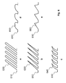
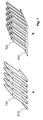
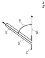
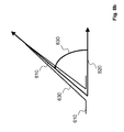
In einer bevorzugten Ausführungsform weist die Oberflächenstruktur Elemente auf, die schräg zur Oberfläche orientiert sind. Dabei können die Elemente in Form von Fasern, Nadeln, Noppen, Lamellen, Spitzen, Zacken oder Stiften ausgeführt sein.In a preferred embodiment, the surface structure has elements that are oriented obliquely to the surface. The elements may be in the form of fibers, needles, nubs, lamellae, tips, serrations or pins.
Im Sinne der Erfindung ist eine schräge Orientierung der Elemente zur Oberfläche weitestgehend derart zu verstehen, dass der Winkel zwischen der Ausrichtung jedes Elements zur Oberfläche der Vorrichtung kleiner als 90° beträgt.For the purposes of the invention, an oblique orientation of the elements to the surface is to be understood as far as possible such that the angle between the orientation of each element to the surface of the device is less than 90 °.
Geeignete Materialien, aus denen die Elemente der Oberflächenstruktur gefertigt sein können, wären unter anderem Titan, Edelstahl, Silikon, biokompatible Polymere, bioresorbierbare Polymere wie Polymere der Glykolsäure oder Copolymere aus Glykolyd und Lactid oder Polymere aus Dioxanon, Polyetheretherketon (PEEK), bioresorbierbare Magnesiumverbindungen, resorbierbare Zuckerstrukturen wie Mannitol.Suitable materials from which the elements of the surface structure may be made, include titanium, stainless steel, silicone, biocompatible polymers, bioresorbable polymers such as glycolic acid or copolymers of glycolide and lactide or polymers of dioxanone, polyetheretherketone (PEEK), bioresorbable magnesium compounds, absorbable sugar structures such as mannitol.
In einer weiteren Ausführungsform sind an der Vorrichtung Mittel zur Steuerung einer Verschiebungsrichtung der Vorrichtung angebracht.In a further embodiment, means for controlling a displacement direction of the device are attached to the device.
Die Mittel zur Steuerung der Verschiebungsrichtung können dazu dienen, die die Verschiebungsrichtung und/oder -Strecke während der Einbringung der Vorrichtung in den Körper von außen kontrollieren und ändern zu können. Derartige Mittel können beispielsweise in Form von Steuerfäden oder von Mandrins ausgeführt sein.
- Fig. 1
- Ausführungsform der erfindungsgemäßen Vorrichtung;
- Fig. 2
- Ausführungsform der erfindungsgemäßen Vorrichtung mit an der Vorrichtung angebrachten Mitteln zur Steuerung der Verschiebungsrichtung;
- Fig. 3a
- Ausführungsform der erfindungsgemäßen Vorrichtung als Trägereinrichtung, bei der die Oberflächenstruktur Teil der Trägereinrichtung ist;
- Fig. 3b
- Am Implantationsort kann das Implantat von der Trägereinrichtung getrennt werden;
- Fig. 4a
- Ausführungsform der erfindungsgemäßen Vorrichtung, bei der die Vorrichtung eine Folie mit der Oberflächenstruktur aufweist;
- Fig. 4b
- Folie mit Oberflächenstruktur ist von der Vorrichtung ablösbar;
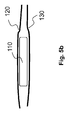
- Fig. 5a
- Ausführungsform der erfindungsgemäßen Vorrichtung, bei der die Anisotropie des Haftreibungskoeffizienten der Oberflächenstruktur aufhebbar ist;
- Fig. 5b
- Erfindungsgemäße Vorrichtung nach Aufhebung der Anisotropie des Haftreibungskoeffizienten der Oberflächenstruktur
- Fig. 6a-e
- Mögliche Ausführungsformen der Elemente der Oberflächenstruktur
- Fig. 7a-c
- Mögliche Ausführungsformen der Elemente der Oberflächenstruktur als Einzelelemente oder Lamellenstruktur
- Fig. 8a-b
- Winkel zwischen Ausrichtung eines Elements zur Oberfläche der Vorrichtung
- Fig. 9
- Detaillierte Bestimmungsmethode der Definition einer schrägen Orientierung eines Elements der Oberflächenstruktur zur Oberfläche der Vorrichtung
- Fig. 1
- Embodiment of the device according to the invention;
- Fig. 2
- Embodiment of the device according to the invention with devices mounted on the device for controlling the displacement direction;
- Fig. 3a
- Embodiment of the device according to the invention as a support means, in which the surface structure is part of the support means;
- Fig. 3b
- At the implantation site, the implant can be separated from the carrier device;
- Fig. 4a
- Embodiment of the device according to the invention, in which the device comprises a film having the surface structure;
- Fig. 4b
- Film with surface structure is removable from the device;
- Fig. 5a
- Embodiment of the device according to the invention, in which the anisotropy of the static friction coefficient of the surface structure can be canceled;
- Fig. 5b
- Device according to the invention after cancellation of the anisotropy of the static friction coefficient of the surface structure
- Fig. 6a-e
- Possible embodiments of the elements of the surface structure
- Fig. 7a-c
- Possible embodiments of the elements of the surface structure as individual elements or lamellar structure
- Fig. 8a-b
- Angle between alignment of an element to the surface of the device
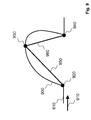
- Fig. 9
- Detailed method of determination of the definition of an oblique orientation of an element of the surface structure to the surface of the device
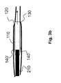
In
Die Vorrichtung besitzt in einer Ausführungsform einen Stimulationspol 340. Die Oberflächenstruktur ist auf den Folien 350 und 350' aufgebracht, welche auf der Vorrichtung 110 fixiert sind. Nach Erreichen des Implantationsortes können die Folien 350 und 350' von der Vorrichtung 110 getrennt werden, gezeigt in
In
Tritt der Fall ein, dass ein Winkel bzw. sind die zwei den winkelbildenden Schenkel nicht eindeutig erkennbar oder bestimmbar sind, beispielsweise aufgrund einer speziellen Geometrie der Elemente der Oberflächenstruktur, so ist für die Definition der schrägen Orientierung der Elemente zur Oberfläche der folgenden Methode, die in
- der Bewegungsrichtung mit dem kleinsten Haftreibungskoeffizienten der Oberflächenstruktur und
- dem Normalvektor der Oberfläche der Vorrichtung.
- the direction of movement with the smallest coefficient of static friction of the surface structure and
- the normal vector of the surface of the device.
Dabei wird ein Querschnitt generiert, wobei 900 die Kante darstellt, welche das Element umreißt. Anschließend wird im Querschnitt die Kante eines Elements in eine Richtung 910 abgefahren. Dabei werden folgende Punkte in der angegebenen Reihenfolge bestimmt:
Punkt 920 auf der Kante des Elements, der eine kleinste Distanz zur Oberfläche der Vorrichtung besitztPunkt 930 auf der Kante des Elements, der den ersten Punkt mit der größten Distanz zur Oberfläche der Vorrichtung darstellt, der hinter Punkt 920 liegtPunkt 940 auf der Kante des Elements, der hinter A liegt und die kleinste Distanz zur Oberfläche der Vorrichtung besitzt.
-
Point 920 on the edge of the element which has a smallest distance to the surface of the device -
Point 930 on the edge of the element representing the first point with the greatest distance to the surface of the device that lies behindpoint 920 -
Point 940 on the edge of the element which is behind A and has the smallest distance to the surface of the device.
Es werden zwei Linien 950 und 960 gebildet, wobei
Linie 950 dieVerbindung zwischen Punkt 920 und 930 darstelltLinie 960 dieVerbindung zwischen Punkt 930 und 940 darstellt.
-
Line 950 represents the connection betweenpoint -
Line 960 represents the connection betweenpoints
So wird die Orientierung eines Elements zur Oberfläche als schräg bezeichnet, wenn Linie 950 und Linie 960 nicht gleich lang sind.Thus, the orientation of an element to the surface is said to be skewed if
Eine bevorzugte Anwendungsmöglichkeit für die vorliegende Erfindung stellt ein Herzschrittmacher dar, der am Epikard (äußerste Schicht der Herzwand) implantiert wird, im Folgenden als epikardialer Herzschrittmacher bezeichnet. Das Epikard liegt eng am Perikard (Herzbeutel) an, wobei sich die zwei Gewebsoberflächen durch die natürliche Pumpbewegung des Herzens andauernd relativ zueinander bewegen. Unter Anwendung von Implantationsmethoden nach dem Stand der Technik wäre somit das Epikard als Implantationsort schwer zugänglich. Mit einem mit der erfindungsgemäßen Oberflächenstruktur versehenen Implantat ist es möglich, das Implantat an einen vorgesehenen Implantationsort am Epikard einzubringen, in dem die Eigenbewegung des Herzens und die relative Bewegung von Epikard und Perikard zueinander genutzt werden. Dazu wird das Implantat zuerst an eine geeignete Stelle zwischen Epikard und Perikard platziert, sodass die Oberflächenstruktur in Kontakt zu mindestens einer der Gewebsschichten steht. Durch die Anisotropie des Haftreibungskoeffizienten der Oberflächenstruktur und der relativen Bewegung beider Gewebsschichten zueinander wird so das Implantat entlang der zwei Grenzschichten in eine Richtung bewegt, die bezüglich der Oberflächenstruktur und deren erfindungsgemäßen Eigenschaften eine geringe Haftreibung aufweist.A preferred application for the present invention is a pacemaker implanted on the epicardium (outermost layer of the heart wall), hereinafter referred to as epicardial pacemaker. The epicardial fits closely to the pericardium, with the two tissue surfaces constantly moving relative to each other due to the natural pumping motion of the heart. Thus, using prior art implantation methods, the epicardium would be difficult to access as the site of implantation. With an implant provided with the surface structure according to the invention, it is possible to introduce the implant to an intended implantation site on the epicardium, in which the proper motion of the heart and the relative movement of the epicardium and pericardium are used. For this purpose, the implant is first placed at a suitable location between epicardium and pericardium so that the surface structure is in contact with at least one of the tissue layers. As a result of the anisotropy of the static friction coefficient of the surface structure and the relative movement of both tissue layers relative to one another, the implant is moved along the two boundary layers in a direction which has a low static friction with respect to the surface structure and its properties according to the invention.
Die vorliegende Erfindung ist anwendbar auf verschiedenartige aktive und passive, temporäre und dauerhafte Implantate, wie zum Beispiel kardiale Stimulatoren, Neurostimulatoren, Pulsgeneratoren, alle Arten von Sensoren und Sensorleitungen, Medikamententräger, Radionuklidträger, medizinische Marker wie z.B. Röntgenmarker, temporäre und permanente Katheter, Naht- und Verschlusssysteme.The present invention is applicable to a variety of active and passive, temporary and permanent implants, such as cardiac stimulators, neurostimulators, pulse generators, all types of sensors and sensor leads, drug carriers, radionuclide carriers, medical markers, e.g. X-ray markers, temporary and permanent catheters, suture and closure systems.
Beispielhafte weitere Implantationsorte stellen sub- oder intrameningiale, intrapleurale Lagen sowie Positionen zwischen Organen oder Organspalten (z.B. Leber, Niere, Magen, Zwerchfell), Harnröhre, Blutgefäßen dar. Dabei muss für die Einbringung der Vorrichtung nicht zwingend eine körpereigene Bewegung einer körperinternen Grenzfläche vorhanden sein bzw. genutzt werden. Eine solche Bewegung kann auch von außen induziert werden.Exemplary further implantation sites represent sub- or intrameningiale, intrapleural layers and positions between organs or organ fissures (eg liver, kidney, stomach, diaphragm), urethra, blood vessels. It must be for the introduction of the device Not necessarily a body-own movement of a body-internal interface to be present or used. Such a movement can also be induced from the outside.
Claims (13)
Priority Applications (2)
| Application Number | Priority Date | Filing Date | Title |
|---|---|---|---|
| EP15154319.6A EP3053543A1 (en) | 2015-02-09 | 2015-02-09 | Device having a surface structure for driving into the human or animal body |
| US15/009,922 US10293154B2 (en) | 2015-02-09 | 2016-01-29 | Device having a surface structure for insertion into the human or animal body |
Applications Claiming Priority (1)
| Application Number | Priority Date | Filing Date | Title |
|---|---|---|---|
| EP15154319.6A EP3053543A1 (en) | 2015-02-09 | 2015-02-09 | Device having a surface structure for driving into the human or animal body |
Publications (1)
| Publication Number | Publication Date |
|---|---|
| EP3053543A1 true EP3053543A1 (en) | 2016-08-10 |
Family
ID=52469633
Family Applications (1)
| Application Number | Title | Priority Date | Filing Date |
|---|---|---|---|
| EP15154319.6A Withdrawn EP3053543A1 (en) | 2015-02-09 | 2015-02-09 | Device having a surface structure for driving into the human or animal body |
Country Status (2)
| Country | Link |
|---|---|
| US (1) | US10293154B2 (en) |
| EP (1) | EP3053543A1 (en) |
Families Citing this family (1)
| Publication number | Priority date | Publication date | Assignee | Title |
|---|---|---|---|---|
| EP3785616B1 (en) * | 2019-09-02 | 2022-12-07 | BIOTRONIK SE & Co. KG | Implantation catheter |
Citations (7)
| Publication number | Priority date | Publication date | Assignee | Title |
|---|---|---|---|---|
| US20110009801A1 (en) * | 2007-09-12 | 2011-01-13 | Medical And Surgical Review, P.C. | Devices and methods for treatment of obesity |
| US20110021965A1 (en) * | 2007-11-19 | 2011-01-27 | Massachusetts Institute Of Technology | Adhesive articles |
| US20120220917A1 (en) | 2007-07-17 | 2012-08-30 | Tom Silvestrini | Ocular implant with hydrogel expansion capabilities |
| US8398909B1 (en) * | 2008-09-18 | 2013-03-19 | Carnegie Mellon University | Dry adhesives and methods of making dry adhesives |
| US20130218262A1 (en) * | 2010-09-22 | 2013-08-22 | Terumo Kabushiki Kaisha | Biological adhesive sheet and device for bonding sheet |
| US20140180065A1 (en) | 2011-05-11 | 2014-06-26 | The Regents Of The University Of California | Fiduciary markers and methods of placement |
| US20140277443A1 (en) * | 2013-03-15 | 2014-09-18 | Boston Scientific Scimed, Inc. | Superhydrophobic coating for airway mucus plugging prevention |
Family Cites Families (2)
| Publication number | Priority date | Publication date | Assignee | Title |
|---|---|---|---|---|
| US5925074A (en) * | 1996-12-03 | 1999-07-20 | Atrium Medical Corporation | Vascular endoprosthesis and method |
| US7608114B2 (en) * | 2002-12-02 | 2009-10-27 | Gi Dynamics, Inc. | Bariatric sleeve |
-
2015
- 2015-02-09 EP EP15154319.6A patent/EP3053543A1/en not_active Withdrawn
-
2016
- 2016-01-29 US US15/009,922 patent/US10293154B2/en not_active Expired - Fee Related
Patent Citations (7)
| Publication number | Priority date | Publication date | Assignee | Title |
|---|---|---|---|---|
| US20120220917A1 (en) | 2007-07-17 | 2012-08-30 | Tom Silvestrini | Ocular implant with hydrogel expansion capabilities |
| US20110009801A1 (en) * | 2007-09-12 | 2011-01-13 | Medical And Surgical Review, P.C. | Devices and methods for treatment of obesity |
| US20110021965A1 (en) * | 2007-11-19 | 2011-01-27 | Massachusetts Institute Of Technology | Adhesive articles |
| US8398909B1 (en) * | 2008-09-18 | 2013-03-19 | Carnegie Mellon University | Dry adhesives and methods of making dry adhesives |
| US20130218262A1 (en) * | 2010-09-22 | 2013-08-22 | Terumo Kabushiki Kaisha | Biological adhesive sheet and device for bonding sheet |
| US20140180065A1 (en) | 2011-05-11 | 2014-06-26 | The Regents Of The University Of California | Fiduciary markers and methods of placement |
| US20140277443A1 (en) * | 2013-03-15 | 2014-09-18 | Boston Scientific Scimed, Inc. | Superhydrophobic coating for airway mucus plugging prevention |
Also Published As
| Publication number | Publication date |
|---|---|
| US10293154B2 (en) | 2019-05-21 |
| US20160228697A1 (en) | 2016-08-11 |
Similar Documents
| Publication | Publication Date | Title |
|---|---|---|
| DE69532527T2 (en) | SHIELDED SEW CLAMP DEVICE WITH ACTIVATING RING PART | |
| DE102008002389B4 (en) | Device for osteosynthesis and for fixation and stabilization of long bones | |
| DE60226269T2 (en) | SURGICAL FASTENER WITH ANCHOR AND CLIP | |
| DE102008040773A1 (en) | Implantable catheter or electrode lead | |
| DE602005003830T2 (en) | DEVICE FOR FIXING BONE LABELS AFTER A CRANIOTOMY | |
| EP1744681B1 (en) | Blind rivet for adapting biological tissue | |
| DE102015113138B3 (en) | Laser-activated variable-length ossicle prosthesis | |
| DE102008034534A1 (en) | Puncture closure for closing a hollow organ having a puncture opening, in particular a blood vessel | |
| WO2000074557A1 (en) | Intravascularly implantable device | |
| US20190167260A1 (en) | Fixation Device | |
| DE102010021345A1 (en) | Occlusions instrument for closing left atrial auricle of patient, has occluder provided with region that is located from central region to retention region for forming actuated connection between nub region of occluder and auricle wall | |
| EP2987526A1 (en) | Medical implant comprising a fixing device | |
| EP3053543A1 (en) | Device having a surface structure for driving into the human or animal body | |
| AT512534B1 (en) | Nerve cuff electrode assembly | |
| EP2661230B1 (en) | Retraction system | |
| EP3720387A1 (en) | Implant with reservoir | |
| EP2926771B1 (en) | Auditory ossicle prosthesis with loop with longitudinal perforation | |
| DE2547816C3 (en) | Spinal protection implant | |
| DE102005012633A1 (en) | Bioabsorbable medical needle for piercing body tissue has magnesium alloy tip that can contain fibers and particles in the magnesium matrix | |
| EP3923838B1 (en) | System for modifying a human or animal bone | |
| DE102008045877A1 (en) | Medical device for fixing of mitral valve tissue of human patient, has absorption device for absorption of tissue, fixing device for fixing tissue and comprising retainer for surgical wire, and guiding device flexibly retaining anchor wire | |
| DE202007017489U1 (en) | Operating instrument for minimally invasive surgery | |
| WO2016150695A1 (en) | Implantable device for forming a permanent skin access port | |
| EP3326691A1 (en) | Medical implant and systems for intravascular implantation | |
| EP1447054A1 (en) | Device for the removal of implants |
Legal Events
| Date | Code | Title | Description |
|---|---|---|---|
| PUAI | Public reference made under article 153(3) epc to a published international application that has entered the european phase |
Free format text: ORIGINAL CODE: 0009012 |
|
| AK | Designated contracting states |
Kind code of ref document: A1 Designated state(s): AL AT BE BG CH CY CZ DE DK EE ES FI FR GB GR HR HU IE IS IT LI LT LU LV MC MK MT NL NO PL PT RO RS SE SI SK SM TR |
|
| AX | Request for extension of the european patent |
Extension state: BA ME |
|
| STAA | Information on the status of an ep patent application or granted ep patent |
Free format text: STATUS: REQUEST FOR EXAMINATION WAS MADE |
|
| 17P | Request for examination filed |
Effective date: 20170208 |
|
| RBV | Designated contracting states (corrected) |
Designated state(s): AL AT BE BG CH CY CZ DE DK EE ES FI FR GB GR HR HU IE IS IT LI LT LU LV MC MK MT NL NO PL PT RO RS SE SI SK SM TR |
|
| STAA | Information on the status of an ep patent application or granted ep patent |
Free format text: STATUS: EXAMINATION IS IN PROGRESS |
|
| 17Q | First examination report despatched |
Effective date: 20170816 |
|
| STAA | Information on the status of an ep patent application or granted ep patent |
Free format text: STATUS: EXAMINATION IS IN PROGRESS |
|
| STAA | Information on the status of an ep patent application or granted ep patent |
Free format text: STATUS: EXAMINATION IS IN PROGRESS |
|
| STAA | Information on the status of an ep patent application or granted ep patent |
Free format text: STATUS: THE APPLICATION IS DEEMED TO BE WITHDRAWN |
|
| 18D | Application deemed to be withdrawn |
Effective date: 20230425 |