EP3051675B1 - Kurzschlussläufer und asynchronmotor mit derartigen rotor - Google Patents
Kurzschlussläufer und asynchronmotor mit derartigen rotor Download PDFInfo
- Publication number
- EP3051675B1 EP3051675B1 EP15305089.3A EP15305089A EP3051675B1 EP 3051675 B1 EP3051675 B1 EP 3051675B1 EP 15305089 A EP15305089 A EP 15305089A EP 3051675 B1 EP3051675 B1 EP 3051675B1
- Authority
- EP
- European Patent Office
- Prior art keywords
- short
- rotor
- end portion
- strips
- circuit ring
- Prior art date
- Legal status (The legal status is an assumption and is not a legal conclusion. Google has not performed a legal analysis and makes no representation as to the accuracy of the status listed.)
- Active
Links
Images
Classifications
-
- H—ELECTRICITY
- H02—GENERATION; CONVERSION OR DISTRIBUTION OF ELECTRIC POWER
- H02K—DYNAMO-ELECTRIC MACHINES
- H02K17/00—Asynchronous induction motors; Asynchronous induction generators
- H02K17/02—Asynchronous induction motors
- H02K17/16—Asynchronous induction motors having rotors with internally short-circuited windings, e.g. cage rotors
- H02K17/168—Asynchronous induction motors having rotors with internally short-circuited windings, e.g. cage rotors having single-cage rotors
Definitions
- the present invention relates to an electric machine rotor, extending along an axis of rotation and comprising a short-circuit cage having at least one bar and at least a first electrical short-circuit ring, the or each bar having a first end portion, the first end portion being linked to the first short-circuit ring electrically by a first linking means and radially relative to the axis of rotation.
- the present invention also relates to an electrical machine, in particular an asynchronous machine, in particular a motor, comprising a stator and such a rotor.
- a rotor of the aforementioned type is known from documents EP 0 628 675 A1 , GB 268355 A , EP 0546197 A1 , EP2615726 A1 , JP 5631352 A , EP0608675 A1
- the rotor comprises a magnetic mass extending along the axis of rotation and a short-circuit cage.
- the short-circuit cage comprises two short-circuit rings placed on either side of the magnetic mass along the axis of rotation and a plurality of electrically conductive round bars intended to electrically connect the two short-circuit rings.
- the ends of the round or rectangular bars are arranged flexibly or capable of expanding freely in holes adapted to the bars and provided in the short-circuit rings.
- the free arrangement of the ends of the bars in the holes made in the short-circuit rings does not guarantee electrical contacts under all conditions of use, in particular for low rotor rotation speeds, where the centrifugal force is not sufficient to ensure contact pressure between the ends of the bars and the short-circuit rings allowing the passage of electric current without sparking and without excessive heating.
- the aim of the invention is therefore to propose an electric machine rotor making it possible to improve the electrical contact between the bars and the rings of the short-circuit cage.
- the invention also relates to an asynchronous electrical machine, in particular a motor, comprising a stator and a rotor as defined above.
- the electric machine 10 is, preferably, an asynchronous machine, in particular an asynchronous motor.
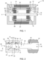
- the machine 10 comprises a frame 12, a stator 14, a rotor 16 and a shaft 18.
- the machine 10 is adapted to operate at very high speeds, for example speeds ranging from 3,000 revolutions per minute to 20,000 revolutions per minute.
- the machine 10 has a high electrical power, for example greater than 10 Megawatts (MW), preferably greater than 50 MW.
- the frame 12 and the stator 14 are known elements, and are therefore not described in more detail.
- the rotor 16 extends along an axis of rotation X-X' also called the longitudinal axis.
- X-X' also called the longitudinal axis.
- the rotor 16 is secured to the shaft 18, and comprises a short-circuit cage 20 and a magnetic mass 22.
- the rotor 16 is a rotor of significant mass, for example greater than 1000 kilograms (kg), preferably greater than 10,000 kilograms (kg).
- the short-circuit cage 20 comprises a first electrical short-circuit ring 24 and a second electrical short-circuit ring 26.
- the short-circuit cage 20 comprises a plurality of electrically conductive bars 28 intended to electrically connect the two short-circuit rings 24, 26, each bar 28 comprising a first end portion 30, a second end portion 32 and a middle portion 34 extending between the end portions 30, 32.
- the short-circuit cage 20 comprises, for each conductive bar 28, a first connecting means 36 arranged between the first end portion 30 and the first short-circuit ring 24, in order to electrically connect the first end portion 30 to the first short-circuit ring 24 radially relative to the axis of rotation X-X'.
- the short-circuit cage 20 comprises, for each conductive bar 28, a second connecting means 38 arranged between the second end portion 32 and the second short-circuit ring 26, in order to electrically connect the second end portion 32 to the second short-circuit ring 26 radially relative to the axis of rotation X-X'.
- the magnetic mass 22 comprises a stack of rotor laminations and a device, not shown, for holding the stack.
- the magnetic mass 22 extends along the longitudinal axis X-X', and is delimited by a periphery.
- the magnetic mass 22 comprises a plurality of housings 40 of bar 28.
- the first short-circuit ring 24 and the second short-circuit ring 26 are identical, or substantially identical.
- Each short-circuit ring 24, 26 is a circular disk arranged coaxially to the axis of rotation X-X'.
- the first short-circuit ring 24 is arranged on one axial side of the magnetic mass 22 while the second short-circuit ring 26 is arranged on the other axial side of the magnetic mass 22.
- Each short-circuit ring 24, 26 is fixed axially relative to the magnetic mass 22 or relative to the shaft 18.
- Each short-circuit ring 24, 26 is, for example, shrunk onto the shaft 18 or fixed to the magnetic mass 22.
- the short-circuit ring 24, 26 is fixed to any other intermediate part secured to the shaft 18 or to the magnetic mass 22.
- Each short-circuit ring 24, 26 is, for example, made of metal, preferably made of copper. Preferably, each short-circuit ring 24, 26 is made in one piece, in particular in one piece.
- Each short-circuit ring 24, 26 is provided with a plurality of axial cavities 42.
- Each axial cavity 42 is suitable for receiving a respective bar 28.
- Each bar 28 is manufactured in one piece, and in particular in one piece.
- the bars 28 are, for example, manufactured from metal, such as copper.
- the bars 28 are arranged parallel to the axis of rotation X-X'. Furthermore, the middle portion 34 of the bars has, for example, a circular section or, alternatively, a rectangular or substantially rectangular section.
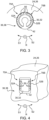
- the end portions 30, 32 of the conductive bar have, for example, a substantially circular section ( figure 3 ) in a transverse plane, perpendicular to the axis of rotation X-X'.
- the end portions 30, 32 of the conductive bar have a substantially rectangular section ( figure 4 ) in the transverse plane.
- the end parts 30, 32 of the conductive bar have a trapezoidal section in said transverse plane.
- Each first connecting means 36 comprises a plurality of electrically conductive flexible strips 50, as shown in the figure 2 .
- each second connecting means 38 also comprises a plurality of electrically conductive flexible strips 50.
- the flexible strips 50 of a respective connecting means 36, 38 are arranged along at least half of the periphery, according to the transverse plane perpendicular to the axis of rotation X-X', of the corresponding end portion 30, 32.
- the flexible strips 50 of a respective connecting means 36, 38 are arranged along substantially the entire periphery of said end portion 30, 32.
- Each flexible strip 50 is preferably movable in rotation around a pivot axis R, visible in the figure 2 and substantially parallel to the axis of rotation X-X'.
- the strips 50 of a respective connecting means 36, 38 are, for example, all movable in rotation about their pivot axis R in the same direction when they are pressed between the end portion 30, 32 of the conductive bar and the corresponding short-circuit ring 24, 26.
- the slats 50 of a respective connecting means 36, 38 are distributed in several sets with directions of rotation around their pivot axis R distinct from one set to another.
- the flexible strips 50 of a respective connecting means 36, 38 are, for example, mechanically and electrically connected. between them by a retaining strip 52, as shown in the Figures 3 and 4 .
- the flexible strips 50 are, for example, substantially V-shaped.
- the flexible strips 50 are preferably made of copper, and the retaining strip 52 is, for example, made of steel or copper.
- Each strip 50 has, for example, a size of 10 mm along the axis R, and is then capable of allowing the circulation of a current of 50 A.
- the flexible strips 50 of a respective connecting means 36, 38 are received in a recess 54 arranged in the respective short-circuit ring 24, 26 and bearing against the respective end portion 30, 32 of the corresponding bar.
- the recess 54 comprises a bottom 56 and two radial walls 58.
- the flexible strips 50 are held in the recess 54 for example with prestressing by applying themselves to the radial walls 58. In the unstressed state of the strips 50, these comprise a central portion 60 which extends outside the recess 54 and which bears against the respective end portion 30, 32 of the corresponding bar.
- the flexible strips 50 are glued into the recess 54 and do not require prestressing in the absence of the bars 28. In this case, in the absence of the bars 28, the strips 50 are out of contact with the radial walls 58.
- the connecting means 36, 38 comprise at least one stop 62 adapted to limit a radial displacement of the end portion 30, 32 under the centrifugal force Fc when the rotor 16 is rotated, in order to limit the crushing of the flexible strips 50, while limiting the bending and associated stress under centrifugal force of the bar 28.
- This stop 62 is, for example, formed by a surface of the short-circuit ring 24, 26, the normal of which is directed radially inwards. In this case, the stop 62 is formed by a wall 64 adjacent to the wall 58.
- the connecting means 36, 38 comprising the electrically conductive flexible strips 50, make it possible to ensure electrical contact between the end portion 30, 32 of the conductive bar 28 and the corresponding short-circuit ring 24, 26, whatever the operating mode of the electrical machine 10, including when the rotor 16 is not driven in rotation, or at low rotation speed.
- the rotational mobility of the strips 50 around the pivot axis R makes it possible to further improve the electrical contact between the end part 30, 32 of the conductive bar and the short-circuit ring 24, 26.
- the flexible strips 50 of a respective connecting means 36, 38 are distributed into a first set 70A and a second set 70B, the strips of the first set 70A being connected to each other by a first holding strip 52A and the strips of the second set 70B being connected to each other by a second holding strip 52B.
- the blades 50 of the first set 70A are movable in rotation about their pivot axis R in a first direction S1 when they are pressed between the end part 30, 32 of the conductive bar and the corresponding short-circuit ring 24, 26.
- the blades 50 of the second set 70B are movable in rotation about their pivot axis R in a second direction S2 when they are pressed between the end part 30, 32 of the conductive bar and the corresponding short-circuit ring 24, 26, the second direction S2 being opposite to the first direction S1.
- the distribution of the flexible strips 50 of a corresponding connecting means 36, 38 into two sets 70A, 70B makes it easier to insert said strips 50 between the end part 30, 32 of the conductive bar and the corresponding short-circuit ring 24, 26.
- the particular arrangement of the two assemblies 70A, 70B such that the blades 50 of the two assemblies are movable in rotation about their pivot axis R in opposite directions S1, S2 from one assembly to the other, makes it possible to further improve the electrical contact between the end portion 30, 32 of the conductive bar and the corresponding short-circuit ring 24, 26.
- the blades 50 of the first assembly 70A are as much prestressed as the blades 50 of the second assembly 70B.
- this particular arrangement of two sets 70A, 70B allows for electrical contact between the part end portion 30, 32 of the conductive bar and the corresponding short-circuit ring 24, 26 which is less dependent on the rotational speed of the rotor 16 and the associated centrifugal force Fc, and of substantially the same quality (electrical contact pressure) along substantially the entire periphery of the end portion 30, 32 of the conductive bar 28.
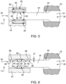
- FIG. 5 illustrates a second embodiment of the invention for which the elements identical to the first embodiment, described above, are identified by identical references, and are not described again.
- the stop 62 and its wall 64 are also present in this second embodiment, opposite the end of the end part 30, 32 (on the far left on the figure 5 ).
- At least one connecting means 36, 38 comprises a socket 80, a first group 82 of flexible strips and a second group 84 of flexible strips, the strips 50 being electrically conductive and integral with the socket 80.
- the first group of strips 82 is received at the outer periphery of the socket 80 and bearing against the respective short-circuit ring 24, 26, and the second group of strips 84 is received at the inner periphery of the socket 80 and bearing against the respective end portion 30, 32 of the corresponding bar 28.
- the sleeve 80 has, along the plane transverse to the axis of rotation X-X', a section of shape substantially identical to that of the section of the end part 30, 32 along said transverse plane.
- the socket 80 is, for example, in the shape of a cylinder when the corresponding end portion 30, 32 has a substantially circular section.
- first groups 82 of blades are received at the outer periphery of the socket 80 and in abutment against the short-circuit ring 24, 26, the first groups 82 being arranged successively along the pivot axis R substantially parallel to the axis of rotation X-X'.
- the socket 80 then comprises an intermediate part extending in a plane substantially perpendicular to the pivot axis R and arranged between two successive first groups 82.
- the connecting means 36, 38 then comprises several rows of strips 50 external to the sleeve 80 and arranged successively along the pivot axis R.
- the second groups 84 of slats are received at the inner periphery of the sleeve 80 and bearing against the respective end portion 30, 32 of the corresponding bar 28, the second groups 84 being arranged successively along the pivot axis R substantially parallel to the axis of rotation X-X'.
- the number of second groups 84 is preferably equal to 2 or 3.
- the sleeve 80 then comprises an intermediate portion extending in a plane substantially perpendicular to the pivot axis R and arranged between two successive second groups 84.
- the connecting means 36, 38 then comprises several rows of slats 50 inside the sleeve 80 and arranged successively along the pivot axis R.
- the number of first group(s) 82 is not necessarily equal to the number of second group(s) 84.
- the connecting means 36, 38 comprises for example a single first group 82 and two second groups 84, and the connecting means 36, 38 is for example capable of allowing the flow of a current of 2000 A.
- the connecting means 36, 38 comprises two first groups 82 and three second groups 84, and the connecting means 36, 38 is for example capable of allowing the flow of a current of 3000 A.
- the aforementioned current values given for information purposes depend not only on the number of first group(s) 82 and second group(s) 84, but also on the dimensions of the flexible strips 50 of each of the groups 82, 84.
- the operation of the electric machine 10 according to the second embodiment is identical to that of the first embodiment, and is not described again.
- the advantages of the electric machine 10, in particular of the connecting means 36, 38, according to the second embodiment are similar to those of the first embodiment.
- the connecting means 36, 38 according to this second embodiment also make it possible to arrange several rows of flexible strips 50 successively along the pivot axis R substantially parallel to the axis of rotation XX' and thus to increase the maximum value of the current capable of passing through the connecting means 36, 38.
- the connecting means 36, 38 according to this second embodiment also make it possible to facilitate the assembly of said connecting means 36, 38 between the short-circuit ring 24, 26 and the respective end portion 30, 32 of the corresponding bar 28.
- the stop function 62 limiting the radial displacement under the centrifugal force Fc of the end portion 30, 32 is integrated in the sleeve 80.
- FIG. 6 illustrates a third embodiment of the invention for which the elements identical to the first embodiment, described previously, are identified by identical references, and are not described again.
- the flexible strips 50 of a respective connecting means 36, 38 are received in a recess 90 arranged in the respective end portion 30, 32 of the corresponding bar 28 and bearing against the respective short-circuit ring 24, 26.
- the recess 90 comprises a bottom 92 and two radial walls 94.
- the flexible strips 50 are held in the recess 90, for example with prestressing by applying themselves to the radial walls 94. In the unstressed state of the strips 50, their central part 60 extends outside the recess 90, and bears against the corresponding short-circuit ring 24, 26.
- the flexible strips 50 are glued into the recess 90 and do not require prestressing in the absence of the short-circuit ring 24, 26. In this case, in the absence of the short-circuit ring 24, 26, the strips 50 are out of contact with the radial walls 94.
- the connecting means 36, 38 comprise at least one stop 96 adapted to limit a radial displacement of the end portion 30, 32 under the centrifugal force Fc when the rotor 16 is rotated, in order to limit the crushing of the flexible strips 50, while limiting the bending and associated stress under centrifugal force of the bar 28.
- This stop 96 is, for example, formed by a surface of the end portion 30, 32, the normal of which is directed radially inwards. In this case, the stop 96 is formed by a wall 98 adjacent to the radial wall 94.
- the connecting means 36, 38 comprising the electrically conductive flexible strips 50, make it possible to ensure electrical contact between the end portion 30, 32 of the conductive bar 28 and the corresponding short-circuit ring 24, 26 regardless of the operating mode of the electrical machine 10, including when the rotor 16 is not driven in rotation, or at low rotation speed.
- the end portion 30, 32 and the associated short-circuit ring 24, 26 form a clearance J2 ( figure 6 ) allowing a radially outward displacement of the end portion 30, 32 against the force of certain lamellae 50.
- the clearance J2 like the clearance J1 of the first embodiment, between the stop 96 with its wall 98 and the short-circuit ring 24, 26 limits the radial displacement of the end portion 30, 32 under the centrifugal force Fc, thus limiting the stresses in the bar 28 and the lamellae 50.
- the rotor 16 of the electrical machine 10 makes it possible to improve the electrical contact between the conductive bars 28 and the rings 24, 26 of the short-circuit cage 20, and this for a very wide range of rotation speeds of the rotor 16, going from stopping to very high rotation speeds, for example from 3000 revolutions per minute to 20,000 revolutions per minute.
Landscapes
- Engineering & Computer Science (AREA)
- Power Engineering (AREA)
- Insulation, Fastening Of Motor, Generator Windings (AREA)
- Induction Machinery (AREA)
- Motor Or Generator Current Collectors (AREA)
Claims (9)
- Rotor (16) einer elektrischen Maschine (10), der sich entlang einer Rotationsachse (X-X') erstreckt und einen Kurzschlusskäfig (20) umfasst, der mindestens einen Stab (28) und mindestens einen ersten Kranz (24) für elektrischen Kurzschluss aufweist, wobei der oder jeder Stab (28) einen ersten Endabschnitt (30) aufweist, wobei der erste Endabschnitt (30) mit dem ersten Kurzschlusskranz (24) elektrisch durch ein erstes Verbindungsmittel (36) verbunden ist und radial in Bezug auf die Rotationsachse (X-X'), wobei der Rotor (16) umfasst:- das oder jedes erste Verbindungsmittel (36) zwischen einem jeweiligen ersten Endabschnitt (30), und dem ersten Kurzschlusskranz (24) umfasst eine Vielzahl von elektrisch leitenden flexiblen Lamellen (50) enthält;- den Kurzschlusskäfig (20), einen zweiten Kranz (26) für elektrischen Kurzschluss enthaltend, wobei der oder jeder Stab (28) einen zweiten Endabschnitt (32) aufweist, wobei der zweite Endabschnitt (32) mit dem zweiten Kurzschlusskranz (26) elektrisch durch ein zweites Verbindungsmittel (38) verbunden ist und radial in Bezug auf die Rotationsachse (X-X'), wobei das oder jedes zweite Verbindungsmittel (38) zwischen einem jeweiligen zweiten Endabschnitt (32) und dem zweiten Kurzschlusskranz (26) ebenfalls eine Vielzahl von elektrisch leitenden flexiblen Lamellen (50) umfasst;- die flexiblen Lamellen (50) eines jeweiligen Verbindungsmittels (36, 38), die entlang mindestens der Hälfte des Umfangs in einer Querebene senkrecht zur Rotationsachse (X-X') des entsprechenden Endabschnitts (30, 32) angeordnet sind, dadurch gekennzeichnet, dass:- die flexiblen Lamellen (50) eines jeweiligen Verbindungsmittels (36, 38) mechanisch und elektrisch durch mindestens ein Halteband (52) miteinander verbunden sind.
- Rotor (16) nach Anspruch 1, wobei die flexiblen Lamellen (50) eines jeweiligen Verbindungsmittels (36, 38) entlang von mindestens drei Vierteln des Umfangs angeordnet sind, der Querebene des Endabschnitts (30, 32) folgend, vorzugsweise im Wesentlichen entlang des gesamten Umfangs, der Querebene des Endabschnitts (30, 32) folgend.
- Rotor (16) nach Anspruch 1 oder 2, wobei jede flexible Lamelle (50) in Rotation um eine Schwenkachse (R) beweglich ist, die im Wesentlichen parallel zur Rotationsachse (X-X') ist.
- Rotor (16) nach einem der Ansprüche 1 bis 3, wobei die flexiblen Lamellen (50) eines jeweiligen Verbindungsmittels (36, 38) in eine erste Baugruppe (70A) und eine zweite Baugruppe (70B) unterteilt sind, wobei die Lamellen der ersten Baugruppe (70A) durch ein erstes Halteband (52A) miteinander verbunden sind und die Lamellen der zweiten Baugruppe (70B) durch ein zweites Halteband (52B) miteinander verbunden sind.
- Rotor (16) nach Anspruch 3 und 4 zusammengenommen, wobei die Lamellen der ersten Baugruppe (70A) in einer ersten Richtung (S1) um ihre Schwenkachse (R) in Rotation beweglich sind, und die Lamellen der zweiten Baugruppe (70B) in einer zweiten Richtung (S2), die der ersten Richtung (S1) entgegengesetzt ist, um ihre Schwenkachse (R) in Rotation beweglich sind.
- Rotor (16) nach einem der vorhergehenden Ansprüche, wobei mindestens ein Verbindungsmittel (36, 38) eine Hülse (80) enthält und mindestens zwei Gruppen (82, 84) von flexiblen Lamellen (50), die elektrisch leitend und mit der Hülse (80) fest verbunden sind, wobei mindestens eine erste Gruppe von Lamellen (82) am äußeren Umfang der Hülse (80) aufgenommen und gegen den jeweiligen Kurzschlusskranz (24, 26) abgestützt ist, und mindestens eine zweite Gruppe von Lamellen (84) am inneren Umfang der Hülse (80) aufgenommen und gegen den jeweiligen Endabschnitt (30, 32) des entsprechenden Stabes (28) abgestützt ist.
- Rotor (16) nach einem der Ansprüche 1 bis 5, wobei die flexiblen Lamellen (50) eines jeweiligen Verbindungsmittels (36, 38) in einer Aussparung (54) aufgenommen werden, die im jeweiligen Kurzschlusskranz (24, 26) eingerichtet ist, und gegen den jeweiligen Endabschnitt (30, 32) des entsprechenden Stabes abgestützt sind.
- Rotor (16) nach einem der Ansprüche 1 bis 5, wobei die flexiblen Lamellen (50) eines jeweiligen Verbindungsmittels (36, 38) in einer Aussparung (90) aufgenommen werden, die im jeweiligen Endabschnitt (30, 32) des entsprechenden Stabes (28) eingerichtet ist, und gegen den jeweiligen Kurzschlusskranz (24, 26) abgestützt sind.
- Elektrische Maschine, insbesondere eine Asynchronmaschine, besonders ein Motor, der einen Stator und einen Rotor (16) umfasst, dadurch gekennzeichnet, dass der Rotor (16) ein Rotor nach einem der vorhergehenden Ansprüche ist.
Priority Applications (3)
| Application Number | Priority Date | Filing Date | Title |
|---|---|---|---|
| EP15305089.3A EP3051675B1 (de) | 2015-01-27 | 2015-01-27 | Kurzschlussläufer und asynchronmotor mit derartigen rotor |
| PCT/EP2016/051098 WO2016120133A1 (fr) | 2015-01-27 | 2016-01-20 | Rotor à cage d'écureuil et moteur asynchrone comportant un tel rotor |
| US15/546,930 US10505433B2 (en) | 2015-01-27 | 2016-01-20 | Squirrel-cage rotor, and asynchronous motor comprising such a rotor |
Applications Claiming Priority (1)
| Application Number | Priority Date | Filing Date | Title |
|---|---|---|---|
| EP15305089.3A EP3051675B1 (de) | 2015-01-27 | 2015-01-27 | Kurzschlussläufer und asynchronmotor mit derartigen rotor |
Publications (2)
| Publication Number | Publication Date |
|---|---|
| EP3051675A1 EP3051675A1 (de) | 2016-08-03 |
| EP3051675B1 true EP3051675B1 (de) | 2024-11-13 |
Family
ID=52991653
Family Applications (1)
| Application Number | Title | Priority Date | Filing Date |
|---|---|---|---|
| EP15305089.3A Active EP3051675B1 (de) | 2015-01-27 | 2015-01-27 | Kurzschlussläufer und asynchronmotor mit derartigen rotor |
Country Status (3)
| Country | Link |
|---|---|
| US (1) | US10505433B2 (de) |
| EP (1) | EP3051675B1 (de) |
| WO (1) | WO2016120133A1 (de) |
Families Citing this family (28)
| Publication number | Priority date | Publication date | Assignee | Title |
|---|---|---|---|---|
| US20190236559A1 (en) | 2018-01-31 | 2019-08-01 | Salesforce.Com, Inc. | Systems, methods, and apparatuses for implementing smart flow contracts using distributed ledger technologies in a cloud based computing environment |
| US11257073B2 (en) | 2018-01-31 | 2022-02-22 | Salesforce.Com, Inc. | Systems, methods, and apparatuses for implementing machine learning models for smart contracts using distributed ledger technologies in a cloud based computing environment |
| US10701054B2 (en) | 2018-01-31 | 2020-06-30 | Salesforce.Com, Inc. | Systems, methods, and apparatuses for implementing super community and community sidechains with consent management for distributed ledger technologies in a cloud based computing environment |
| FR3086122B1 (fr) * | 2018-09-19 | 2020-10-16 | Ge Energy Power Conversion Technology Ltd | Rotor pour machine electrique asynchrone a arbre non traversant |
| US11288280B2 (en) | 2018-10-31 | 2022-03-29 | Salesforce.Com, Inc. | Systems, methods, and apparatuses for implementing consumer data validation, matching, and merging across tenants with optional verification prompts utilizing blockchain |
| FR3088150B1 (fr) * | 2018-11-06 | 2022-02-18 | Ge Energy Power Conversion Technology Ltd | Rotor a cage d'ecureuil et machine electrique asynchrone associee |
| FR3090234B1 (fr) | 2018-12-14 | 2021-11-12 | Ge Energy Power Conversion Technology Ltd | Rotor à arbre non traversant et machine électrique tournante associée |
| FR3090233B1 (fr) * | 2018-12-14 | 2022-06-24 | Ge Energy Power Conversion Technology Ltd | Barre conductrice, rotor et machine électrique tournante associés |
| US11783024B2 (en) | 2019-01-31 | 2023-10-10 | Salesforce, Inc. | Systems, methods, and apparatuses for protecting consumer data privacy using solid, blockchain and IPFS integration |
| US11886421B2 (en) | 2019-01-31 | 2024-01-30 | Salesforce, Inc. | Systems, methods, and apparatuses for distributing a metadata driven application to customers and non-customers of a host organization using distributed ledger technology (DLT) |
| US11875400B2 (en) | 2019-01-31 | 2024-01-16 | Salesforce, Inc. | Systems, methods, and apparatuses for dynamically assigning nodes to a group within blockchains based on transaction type and node intelligence using distributed ledger technology (DLT) |
| US11824864B2 (en) | 2019-01-31 | 2023-11-21 | Salesforce, Inc. | Systems, methods, and apparatuses for implementing a declarative and metadata driven blockchain platform using distributed ledger technology (DLT) |
| US11811769B2 (en) | 2019-01-31 | 2023-11-07 | Salesforce, Inc. | Systems, methods, and apparatuses for implementing a declarative, metadata driven, cryptographically verifiable multi-network (multi-tenant) shared ledger |
| US11244313B2 (en) | 2019-01-31 | 2022-02-08 | Salesforce.Com, Inc. | Systems, methods, and apparatuses for implementing declarative smart actions for coins and assets transacted onto a blockchain using distributed ledger technology (DLT) |
| US11971874B2 (en) | 2019-01-31 | 2024-04-30 | Salesforce, Inc. | Systems, methods, and apparatuses for implementing efficient storage and validation of data and metadata within a blockchain using distributed ledger technology (DLT) |
| US11803537B2 (en) | 2019-01-31 | 2023-10-31 | Salesforce, Inc. | Systems, methods, and apparatuses for implementing an SQL query and filter mechanism for blockchain stored data using distributed ledger technology (DLT) |
| US11899817B2 (en) | 2019-01-31 | 2024-02-13 | Salesforce, Inc. | Systems, methods, and apparatuses for storing PII information via a metadata driven blockchain using distributed and decentralized storage for sensitive user information |
| US11876910B2 (en) | 2019-01-31 | 2024-01-16 | Salesforce, Inc. | Systems, methods, and apparatuses for implementing a multi tenant blockchain platform for managing Einstein platform decisions using distributed ledger technology (DLT) |
| US11488176B2 (en) | 2019-01-31 | 2022-11-01 | Salesforce.Com, Inc. | Systems, methods, and apparatuses for implementing certificates of authenticity of digital twins transacted onto a blockchain using distributed ledger technology (DLT) |
| US11038771B2 (en) | 2019-04-26 | 2021-06-15 | Salesforce.Com, Inc. | Systems, methods, and apparatuses for implementing a metadata driven rules engine on blockchain using distributed ledger technology (DLT) |
| US11880349B2 (en) | 2019-04-30 | 2024-01-23 | Salesforce, Inc. | System or method to query or search a metadata driven distributed ledger or blockchain |
| US11995647B2 (en) | 2019-04-30 | 2024-05-28 | Salesforce, Inc. | System and method of providing interoperable distributed and decentralized ledgers using consensus on consensus and delegated consensus |
| US11824970B2 (en) | 2020-01-20 | 2023-11-21 | Salesforce, Inc. | Systems, methods, and apparatuses for implementing user access controls in a metadata driven blockchain operating via distributed ledger technology (DLT) using granular access objects and ALFA/XACML visibility rules |
| US11144335B2 (en) | 2020-01-30 | 2021-10-12 | Salesforce.Com, Inc. | System or method to display blockchain information with centralized information in a tenant interface on a multi-tenant platform |
| US11611560B2 (en) | 2020-01-31 | 2023-03-21 | Salesforce.Com, Inc. | Systems, methods, and apparatuses for implementing consensus on read via a consensus on write smart contract trigger for a distributed ledger technology (DLT) platform |
| US20220010734A1 (en) * | 2020-07-08 | 2022-01-13 | Ge Energy Power Conversion Technology Limited | Mechanical drive system and associated motor compressor |
| CN112072818B (zh) * | 2020-08-31 | 2021-07-27 | 珠海格力电器股份有限公司 | 转子、异步电机、压缩机 |
| US12526155B2 (en) | 2022-06-06 | 2026-01-13 | Salesforce, Inc. | Multi-signature wallets in public trust ledger actions via a database system |
Citations (1)
| Publication number | Priority date | Publication date | Assignee | Title |
|---|---|---|---|---|
| EP0608675A1 (de) * | 1993-01-26 | 1994-08-03 | Gec Alsthom Acec Energie S.A. | Elektrischer Motor mit hoher Drehgeschwindigkeit und hoher Leistung |
Family Cites Families (11)
| Publication number | Priority date | Publication date | Assignee | Title |
|---|---|---|---|---|
| GB268355A (en) * | 1926-03-29 | 1927-11-24 | Siemens Schuckertwerke Gmbh | Improvements in or relating to squirrel cage rotors |
| JPS631352A (ja) * | 1986-06-20 | 1988-01-06 | Fuji Electric Co Ltd | かご形回転子 |
| JPH054772U (ja) * | 1991-06-28 | 1993-01-22 | フアナツク株式会社 | 高速誘導型acモータのロータ組立構造 |
| DE4221953C1 (de) * | 1992-07-02 | 1993-10-21 | Aeg Westinghouse Transport | Kurzschlußläufer einer elektrischen Maschine |
| DE4318904A1 (de) | 1993-06-07 | 1995-01-05 | Horst Dr Ing Kinkel | Verfahren zur Bewehrung eines Betonbauwerks, und Bewehrungselemente hierfür |
| US6734588B2 (en) * | 2001-08-02 | 2004-05-11 | Siemens Westinghouse Power Corporation | Sectioned conductor and related methods for accommodating stress and avoiding internal deformations in power generator |
| US7451538B2 (en) * | 2005-09-20 | 2008-11-18 | Reliance Electric Technologies, Llc | Method for fabricating rotor assembly |
| JP5155420B2 (ja) * | 2011-03-11 | 2013-03-06 | ファナック株式会社 | エンドリングとバーをろう付けする誘導電動機のかご形ロータ及びその製造方法 |
| EP2549630B1 (de) * | 2011-07-22 | 2013-10-02 | Siemens Aktiengesellschaft | Kurzschlussläufer einer Asynchronmaschine und Verfahren zur Herstellung eines derartigen Läufers |
| FR2985870B1 (fr) * | 2012-01-16 | 2014-01-03 | Converteam Technology Ltd | Rotor, procede de fabrication et machine electrique correspondants |
| EP3048710B1 (de) * | 2015-01-20 | 2022-10-26 | GE Energy Power Conversion Technology Ltd | Rotor, entsprechendes herstellungsverfahren und entsprechende elektrische maschine |
-
2015
- 2015-01-27 EP EP15305089.3A patent/EP3051675B1/de active Active
-
2016
- 2016-01-20 WO PCT/EP2016/051098 patent/WO2016120133A1/fr not_active Ceased
- 2016-01-20 US US15/546,930 patent/US10505433B2/en active Active
Patent Citations (1)
| Publication number | Priority date | Publication date | Assignee | Title |
|---|---|---|---|---|
| EP0608675A1 (de) * | 1993-01-26 | 1994-08-03 | Gec Alsthom Acec Energie S.A. | Elektrischer Motor mit hoher Drehgeschwindigkeit und hoher Leistung |
Also Published As
| Publication number | Publication date |
|---|---|
| WO2016120133A1 (fr) | 2016-08-04 |
| US10505433B2 (en) | 2019-12-10 |
| EP3051675A1 (de) | 2016-08-03 |
| WO2016120133A4 (fr) | 2016-09-29 |
| US20180026505A1 (en) | 2018-01-25 |
Similar Documents
| Publication | Publication Date | Title |
|---|---|---|
| EP3051675B1 (de) | Kurzschlussläufer und asynchronmotor mit derartigen rotor | |
| EP2789076B1 (de) | Vorrichtung zum führen eines satzes elektrischer drähte für einen elektromotorrotor | |
| EP2627870B1 (de) | Anschlussmodul zwischen einer antriebswelle eines motorlüfters und einem wälzlager | |
| EP2306624B1 (de) | Rotor eines Elektromotors optimiert für grosse Kräfte | |
| EP2615726B1 (de) | Rotor, entsprechendes Herstellungsverfahren und entsprechende elektrische Maschine | |
| EP0608675A1 (de) | Elektrischer Motor mit hoher Drehgeschwindigkeit und hoher Leistung | |
| EP3048703B1 (de) | Magnetische masse für rotor, entsprechender rotor, entsprechende elektrische maschine und herstellungsverfahren für diese masse | |
| FR3057411A1 (fr) | Rotor segmente pour machine asynchrone et machine asynchrone comportant un tel rotor segmente | |
| EP3051674B1 (de) | Kurzschlussläufer für einen asynchronmotor | |
| CA2943461A1 (fr) | Piece de revolution pour un rotor de turbomachine | |
| EP2462361B1 (de) | Vorspannungsvorrichtung mit radialer aktivität | |
| EP3048710B1 (de) | Rotor, entsprechendes herstellungsverfahren und entsprechende elektrische maschine | |
| EP2620662B1 (de) | Elektrische Maschine | |
| EP2618465B1 (de) | Elektrische Maschine, die zwei Rotoren und mindestens zwei Lager umfasst, mit einem Lager zwischen den beiden Rotoren entlang der Rotationsachse | |
| EP3895295B1 (de) | Stromschiene und zugehöriger rotor und rotierende elektrische maschine | |
| WO2011033467A2 (fr) | Rotor de machine asynchrone | |
| EP3726081A1 (de) | Mechanisches system und angekoppelter motorkompressor | |
| EP3576258B1 (de) | Welle für elektrisch umlaufende maschine, rotor und herstellungsverfahren eines solchen rotors | |
| FR3037473A1 (fr) | Rouleau d'effeuillage de plantes et dispositif d'effeuillage le comportant | |
| FR2994107A1 (fr) | Appareil a tambour rotatif comprenant un tambour rotatif et au moins un moteur electrique d'entrainement du tambour, avec un stator s'etendant en regard d'une partie seulement de la circonference du tambour | |
| EP0098199A1 (de) | Läufer mit Ziegeln, insbesondere für Gleichpolmaschinen | |
| EP3389165A1 (de) | Verbesserte führungsvorrichtung einer gesamtheit von elektrischen drähten für rotor eines elektromotors | |
| FR3000150A1 (fr) | Palier de roulement et systeme de blocage axial dudit palier de roulement |
Legal Events
| Date | Code | Title | Description |
|---|---|---|---|
| PUAI | Public reference made under article 153(3) epc to a published international application that has entered the european phase |
Free format text: ORIGINAL CODE: 0009012 |
|
| AK | Designated contracting states |
Kind code of ref document: A1 Designated state(s): AL AT BE BG CH CY CZ DE DK EE ES FI FR GB GR HR HU IE IS IT LI LT LU LV MC MK MT NL NO PL PT RO RS SE SI SK SM TR |
|
| AX | Request for extension of the european patent |
Extension state: BA ME |
|
| STAA | Information on the status of an ep patent application or granted ep patent |
Free format text: STATUS: REQUEST FOR EXAMINATION WAS MADE |
|
| 17P | Request for examination filed |
Effective date: 20161213 |
|
| STAA | Information on the status of an ep patent application or granted ep patent |
Free format text: STATUS: EXAMINATION IS IN PROGRESS |
|
| 17Q | First examination report despatched |
Effective date: 20200706 |
|
| RAP3 | Party data changed (applicant data changed or rights of an application transferred) |
Owner name: GE ENERGY POWER CONVERSION TECHNOLOGY LTD |
|
| P01 | Opt-out of the competence of the unified patent court (upc) registered |
Effective date: 20230530 |
|
| GRAP | Despatch of communication of intention to grant a patent |
Free format text: ORIGINAL CODE: EPIDOSNIGR1 |
|
| STAA | Information on the status of an ep patent application or granted ep patent |
Free format text: STATUS: GRANT OF PATENT IS INTENDED |
|
| RIC1 | Information provided on ipc code assigned before grant |
Ipc: H02K 17/16 20060101AFI20240527BHEP |
|
| INTG | Intention to grant announced |
Effective date: 20240618 |
|
| GRAS | Grant fee paid |
Free format text: ORIGINAL CODE: EPIDOSNIGR3 |
|
| GRAA | (expected) grant |
Free format text: ORIGINAL CODE: 0009210 |
|
| STAA | Information on the status of an ep patent application or granted ep patent |
Free format text: STATUS: THE PATENT HAS BEEN GRANTED |
|
| AK | Designated contracting states |
Kind code of ref document: B1 Designated state(s): AL AT BE BG CH CY CZ DE DK EE ES FI FR GB GR HR HU IE IS IT LI LT LU LV MC MK MT NL NO PL PT RO RS SE SI SK SM TR |
|
| REG | Reference to a national code |
Ref country code: GB Ref legal event code: FG4D Free format text: NOT ENGLISH |
|
| REG | Reference to a national code |
Ref country code: CH Ref legal event code: EP |
|
| REG | Reference to a national code |
Ref country code: IE Ref legal event code: FG4D Free format text: LANGUAGE OF EP DOCUMENT: FRENCH |
|
| REG | Reference to a national code |
Ref country code: DE Ref legal event code: R096 Ref document number: 602015090385 Country of ref document: DE |
|
| REG | Reference to a national code |
Ref country code: LT Ref legal event code: MG9D |
|
| REG | Reference to a national code |
Ref country code: NL Ref legal event code: MP Effective date: 20241113 |
|
| PG25 | Lapsed in a contracting state [announced via postgrant information from national office to epo] |
Ref country code: IS Free format text: LAPSE BECAUSE OF FAILURE TO SUBMIT A TRANSLATION OF THE DESCRIPTION OR TO PAY THE FEE WITHIN THE PRESCRIBED TIME-LIMIT Effective date: 20250313 Ref country code: HR Free format text: LAPSE BECAUSE OF FAILURE TO SUBMIT A TRANSLATION OF THE DESCRIPTION OR TO PAY THE FEE WITHIN THE PRESCRIBED TIME-LIMIT Effective date: 20241113 Ref country code: PT Free format text: LAPSE BECAUSE OF FAILURE TO SUBMIT A TRANSLATION OF THE DESCRIPTION OR TO PAY THE FEE WITHIN THE PRESCRIBED TIME-LIMIT Effective date: 20250313 |
|
| PG25 | Lapsed in a contracting state [announced via postgrant information from national office to epo] |
Ref country code: FI Free format text: LAPSE BECAUSE OF FAILURE TO SUBMIT A TRANSLATION OF THE DESCRIPTION OR TO PAY THE FEE WITHIN THE PRESCRIBED TIME-LIMIT Effective date: 20241113 Ref country code: NL Free format text: LAPSE BECAUSE OF FAILURE TO SUBMIT A TRANSLATION OF THE DESCRIPTION OR TO PAY THE FEE WITHIN THE PRESCRIBED TIME-LIMIT Effective date: 20241113 |
|
| REG | Reference to a national code |
Ref country code: AT Ref legal event code: MK05 Ref document number: 1742429 Country of ref document: AT Kind code of ref document: T Effective date: 20241113 |
|
| PG25 | Lapsed in a contracting state [announced via postgrant information from national office to epo] |
Ref country code: BG Free format text: LAPSE BECAUSE OF FAILURE TO SUBMIT A TRANSLATION OF THE DESCRIPTION OR TO PAY THE FEE WITHIN THE PRESCRIBED TIME-LIMIT Effective date: 20241113 |
|
| PG25 | Lapsed in a contracting state [announced via postgrant information from national office to epo] |
Ref country code: ES Free format text: LAPSE BECAUSE OF FAILURE TO SUBMIT A TRANSLATION OF THE DESCRIPTION OR TO PAY THE FEE WITHIN THE PRESCRIBED TIME-LIMIT Effective date: 20241113 |
|
| PG25 | Lapsed in a contracting state [announced via postgrant information from national office to epo] |
Ref country code: NO Free format text: LAPSE BECAUSE OF FAILURE TO SUBMIT A TRANSLATION OF THE DESCRIPTION OR TO PAY THE FEE WITHIN THE PRESCRIBED TIME-LIMIT Effective date: 20250213 |
|
| PG25 | Lapsed in a contracting state [announced via postgrant information from national office to epo] |
Ref country code: LV Free format text: LAPSE BECAUSE OF FAILURE TO SUBMIT A TRANSLATION OF THE DESCRIPTION OR TO PAY THE FEE WITHIN THE PRESCRIBED TIME-LIMIT Effective date: 20241113 Ref country code: GR Free format text: LAPSE BECAUSE OF FAILURE TO SUBMIT A TRANSLATION OF THE DESCRIPTION OR TO PAY THE FEE WITHIN THE PRESCRIBED TIME-LIMIT Effective date: 20250214 Ref country code: AT Free format text: LAPSE BECAUSE OF FAILURE TO SUBMIT A TRANSLATION OF THE DESCRIPTION OR TO PAY THE FEE WITHIN THE PRESCRIBED TIME-LIMIT Effective date: 20241113 |
|
| PG25 | Lapsed in a contracting state [announced via postgrant information from national office to epo] |
Ref country code: PL Free format text: LAPSE BECAUSE OF FAILURE TO SUBMIT A TRANSLATION OF THE DESCRIPTION OR TO PAY THE FEE WITHIN THE PRESCRIBED TIME-LIMIT Effective date: 20241113 |
|
| PG25 | Lapsed in a contracting state [announced via postgrant information from national office to epo] |
Ref country code: RS Free format text: LAPSE BECAUSE OF FAILURE TO SUBMIT A TRANSLATION OF THE DESCRIPTION OR TO PAY THE FEE WITHIN THE PRESCRIBED TIME-LIMIT Effective date: 20250213 |
|
| PG25 | Lapsed in a contracting state [announced via postgrant information from national office to epo] |
Ref country code: SM Free format text: LAPSE BECAUSE OF FAILURE TO SUBMIT A TRANSLATION OF THE DESCRIPTION OR TO PAY THE FEE WITHIN THE PRESCRIBED TIME-LIMIT Effective date: 20241113 |
|
| PG25 | Lapsed in a contracting state [announced via postgrant information from national office to epo] |
Ref country code: DK Free format text: LAPSE BECAUSE OF FAILURE TO SUBMIT A TRANSLATION OF THE DESCRIPTION OR TO PAY THE FEE WITHIN THE PRESCRIBED TIME-LIMIT Effective date: 20241113 |
|
| PG25 | Lapsed in a contracting state [announced via postgrant information from national office to epo] |
Ref country code: EE Free format text: LAPSE BECAUSE OF FAILURE TO SUBMIT A TRANSLATION OF THE DESCRIPTION OR TO PAY THE FEE WITHIN THE PRESCRIBED TIME-LIMIT Effective date: 20241113 |
|
| PG25 | Lapsed in a contracting state [announced via postgrant information from national office to epo] |
Ref country code: RO Free format text: LAPSE BECAUSE OF FAILURE TO SUBMIT A TRANSLATION OF THE DESCRIPTION OR TO PAY THE FEE WITHIN THE PRESCRIBED TIME-LIMIT Effective date: 20241113 |
|
| PG25 | Lapsed in a contracting state [announced via postgrant information from national office to epo] |
Ref country code: SK Free format text: LAPSE BECAUSE OF FAILURE TO SUBMIT A TRANSLATION OF THE DESCRIPTION OR TO PAY THE FEE WITHIN THE PRESCRIBED TIME-LIMIT Effective date: 20241113 |
|
| PG25 | Lapsed in a contracting state [announced via postgrant information from national office to epo] |
Ref country code: CZ Free format text: LAPSE BECAUSE OF FAILURE TO SUBMIT A TRANSLATION OF THE DESCRIPTION OR TO PAY THE FEE WITHIN THE PRESCRIBED TIME-LIMIT Effective date: 20241113 |
|
| PG25 | Lapsed in a contracting state [announced via postgrant information from national office to epo] |
Ref country code: IT Free format text: LAPSE BECAUSE OF FAILURE TO SUBMIT A TRANSLATION OF THE DESCRIPTION OR TO PAY THE FEE WITHIN THE PRESCRIBED TIME-LIMIT Effective date: 20241113 |
|
| REG | Reference to a national code |
Ref country code: DE Ref legal event code: R097 Ref document number: 602015090385 Country of ref document: DE |
|
| REG | Reference to a national code |
Ref country code: CH Ref legal event code: PL |
|
| PG25 | Lapsed in a contracting state [announced via postgrant information from national office to epo] |
Ref country code: SE Free format text: LAPSE BECAUSE OF FAILURE TO SUBMIT A TRANSLATION OF THE DESCRIPTION OR TO PAY THE FEE WITHIN THE PRESCRIBED TIME-LIMIT Effective date: 20241113 |
|
| PG25 | Lapsed in a contracting state [announced via postgrant information from national office to epo] |
Ref country code: LU Free format text: LAPSE BECAUSE OF NON-PAYMENT OF DUE FEES Effective date: 20250127 Ref country code: MC Free format text: LAPSE BECAUSE OF FAILURE TO SUBMIT A TRANSLATION OF THE DESCRIPTION OR TO PAY THE FEE WITHIN THE PRESCRIBED TIME-LIMIT Effective date: 20241113 |
|
| PLBE | No opposition filed within time limit |
Free format text: ORIGINAL CODE: 0009261 |
|
| STAA | Information on the status of an ep patent application or granted ep patent |
Free format text: STATUS: NO OPPOSITION FILED WITHIN TIME LIMIT |
|
| PG25 | Lapsed in a contracting state [announced via postgrant information from national office to epo] |
Ref country code: BE Free format text: LAPSE BECAUSE OF NON-PAYMENT OF DUE FEES Effective date: 20250131 |
|
| PG25 | Lapsed in a contracting state [announced via postgrant information from national office to epo] |
Ref country code: CH Free format text: LAPSE BECAUSE OF NON-PAYMENT OF DUE FEES Effective date: 20250131 |
|
| 26N | No opposition filed |
Effective date: 20250814 |
|
| REG | Reference to a national code |
Ref country code: BE Ref legal event code: MM Effective date: 20250131 |
|
| PGFP | Annual fee paid to national office [announced via postgrant information from national office to epo] |
Ref country code: GB Payment date: 20251220 Year of fee payment: 12 |
|
| PGFP | Annual fee paid to national office [announced via postgrant information from national office to epo] |
Ref country code: FR Payment date: 20251217 Year of fee payment: 12 |
|
| PG25 | Lapsed in a contracting state [announced via postgrant information from national office to epo] |
Ref country code: IE Free format text: LAPSE BECAUSE OF NON-PAYMENT OF DUE FEES Effective date: 20250127 |
|
| PGFP | Annual fee paid to national office [announced via postgrant information from national office to epo] |
Ref country code: DE Payment date: 20251217 Year of fee payment: 12 |