EP3051674B1 - Rotor à cage d'écureuil pour un moteur asynchrone - Google Patents
Rotor à cage d'écureuil pour un moteur asynchrone Download PDFInfo
- Publication number
- EP3051674B1 EP3051674B1 EP15305088.5A EP15305088A EP3051674B1 EP 3051674 B1 EP3051674 B1 EP 3051674B1 EP 15305088 A EP15305088 A EP 15305088A EP 3051674 B1 EP3051674 B1 EP 3051674B1
- Authority
- EP
- European Patent Office
- Prior art keywords
- rotor
- bar
- section
- magnetic mass
- small base
- Prior art date
- Legal status (The legal status is an assumption and is not a legal conclusion. Google has not performed a legal analysis and makes no representation as to the accuracy of the status listed.)
- Active
Links
Images
Classifications
-
- H—ELECTRICITY
- H02—GENERATION; CONVERSION OR DISTRIBUTION OF ELECTRIC POWER
- H02K—DYNAMO-ELECTRIC MACHINES
- H02K3/00—Details of windings
- H02K3/46—Fastening of windings on the stator or rotor structure
- H02K3/48—Fastening of windings on the stator or rotor structure in slots
-
- H02K17/165—
-
- H—ELECTRICITY
- H02—GENERATION; CONVERSION OR DISTRIBUTION OF ELECTRIC POWER
- H02K—DYNAMO-ELECTRIC MACHINES
- H02K1/00—Details of the magnetic circuit
- H02K1/06—Details of the magnetic circuit characterised by the shape, form or construction
- H02K1/22—Rotating parts of the magnetic circuit
- H02K1/28—Means for mounting or fastening rotating magnetic parts on to, or to, the rotor structures
-
- H—ELECTRICITY
- H02—GENERATION; CONVERSION OR DISTRIBUTION OF ELECTRIC POWER
- H02K—DYNAMO-ELECTRIC MACHINES
- H02K17/00—Asynchronous induction motors; Asynchronous induction generators
- H02K17/02—Asynchronous induction motors
- H02K17/16—Asynchronous induction motors having rotors with internally short-circuited windings, e.g. cage rotors
- H02K17/20—Asynchronous induction motors having rotors with internally short-circuited windings, e.g. cage rotors having deep-bar rotors
Definitions
- the present invention relates to a high-power electric motor rotor intended to operate at particularly high rotation speeds.
- the invention applies to asynchronous motors capable of operating at high peripheral speeds, typically from 100 ms -1 , motors in particular intended for gas and oil applications, whether on land, at sea or even underwater.
- the peripheral speed is the tangential speed calculated at the outer diameter of the rotating rotor.
- High-power electric motors capable of operating at high rotational speeds have many applications.
- manufacture of motors meeting increasing requirements in terms of power and speed imposes new constraints, particularly mechanical, on the rotor of said motors.
- Patent documents EP 0 608 675 A1 And US 5,512,792 describe particularly effective embodiments of rotors for asynchronous electric motors, operating at high power and speeds. A rotor is thus described whose bars constituting the squirrel cage can freely expand, thus making it possible to attenuate the effects due to thermal imbalances.
- the patent document FR 2 950 751 proposes a rotor capable of being integrated into an electric motor with improved characteristics in terms of supported power and peripheral rotation speed, in particular by its capacity to convey greater electrical power through the squirrel cage of the rotor.
- the rotor comprises a plurality of electrical conductors, each conductor being formed by the assembly of a main bar and a secondary bar respectively having a substantially circular section and passing through the magnetic mass of the rotor via a notch.
- the shape and arrangement of each notch are defined so as to ensure sufficient contact between the main bar and the secondary bar to allow the passage of an electric current when the rotor is rotating.
- the document FROM 1488684 discloses a squirrel cage rotor comprising single bars having over their entire length a trapezoidal section forming an isosceles trapezoid and in which the small base of each bar is disposed radially outwardly relative to the rotor axis.
- the invention therefore aims to overcome these problems by proposing an improved rotor.
- the present invention relates in particular to a rotor for an electric motor according to claim 1.
- the invention also relates to a motor capable of driving the rotor as defined above at a peripheral speed greater than or equal to 100 m.s-1 at the level of the external diameter of the magnetic mass.
- the present invention also has the advantage that it makes it possible to significantly improve the power supported by engines such as those described in the patent documents.
- EP 0 608 675 And US 5,512,792 without causing any major changes to the structure of existing rotors.
- the rotor according to the invention finds application in motors capable of operating at high peripheral speeds typically from 100 ms -1 .
- the rotor according to the invention is in particular suitable for use in asynchronous electric motors, in particular intended for gas and oil applications, whether on land, at sea, or even underwater.
- the expression "substantially equal to” will express a relationship of equality to plus or minus 10%, preferably a relationship of equality to plus or minus 5%.
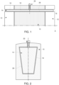
- FIG. 1 shows a longitudinal half-section of a rotor according to a first embodiment, as well as its axis A of rotation.
- the rotor thus represented is adapted to cooperate with a stator and shafts (not shown in the figure 1 ).
- the rotor comprises a magnetic mass 10 enclosed on either side by short-circuit rings 12.
- the magnetic mass 10 results from the assembly of magnetic sheets, the production of which, in particular the means for clamping said sheets together, is described in particular in the patent document US 5,512,792 .
- the rotor comprises a plurality of electrical conductors capable of conducting, through the magnetic mass 10, electrical currents applied to the rotor by the short-circuit rings 12.
- Each electrical conductor consists of a single bar 14.
- each bar 14 is constant or substantially constant over its entire length.
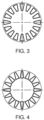
- the section of each bar is trapezoidal in shape. More precisely, the section of each bar 14 is an isosceles trapezoid having a small base and a large base.
- the 14 bars came from material. They are made of copper or copper alloy.
- the short-circuit rings 12 together with the bars 14 form the squirrel cage of the rotor.
- each bar 14 is freely arranged in orifices 16 provided on the periphery of the short-circuit rings 12.
- Each orifice 16 has a section whose shape is complementary to that of the section of the bar 14 that it accommodates, but with slightly larger internal dimensions so that there is a tolerance clearance. This in particular allows the free expansion of the end of the bar 14 in the orifice 16.
- the orifices 16 can be produced by milling or broaching the short-circuit ring 12.
- each bar 14 is received inside a notch 18 made in the magnetic mass.
- Each notch 18 has a section whose shape is complementary to that of the section of the bar 14 which it accommodates, but with slightly larger internal dimensions so that there is a tolerance clearance.
- This tolerance clearance referenced by the number 26 on the figure 2 , ensures the free expansion of the bar 14 in the notch 18 of the magnetic mass 10.
- the bars 14 are fixed to the magnetic mass 10 at a single point using any suitable fixing means 20, such as for example a screw, a pin or by any device, method and fixing accessory, thus allowing a balanced distribution of longitudinal thermal expansion for substantially equal relative movements between the ends of the bar 14 and the short-circuit rings 12.
- any suitable fixing means 20 such as for example a screw, a pin or by any device, method and fixing accessory, thus allowing a balanced distribution of longitudinal thermal expansion for substantially equal relative movements between the ends of the bar 14 and the short-circuit rings 12.
- each bar 14 is arranged so that its large base is oriented radially outwards relative to the axis A of rotation of the rotor.
- the notches 18 and the orifices 16 have a suitable trapezoidal shape.
- the transverse dimensions of the bar 14 are chosen so that the distance between one face of a bar and the face located opposite the neighboring bar is substantially constant.
- one face of a bar and the face located opposite the neighboring bar are parallel to each other, which makes it possible to increase the section of the bars 14 for the same magnetic mass 10, thus allowing an increase in the power of the motor having such a rotor.
- each bar 14 is arranged so that its small base is oriented radially outwards relative to the axis A of rotation of the rotor.
- the notches 18 and the orifices 16 have a suitable trapezoidal shape.
- the support surface of the bar 14 on the notch 18 being smaller than in the first embodiment, the forces at the contact points are greater and risk reducing the service life of the magnetic mass.
- the rotor when the rotor is rotating, it is the small base of the bar 14 which, under the effect of the centrifugal force, accentuates its support on the notch 18 and the orifices 16.
- the four corners of the trapezoidal section are provided with a rounding, of substantially equal value for the corners of the large base and of another substantially equal value for the corners of the small base. This makes it possible to reduce the concentrations of mechanical stress in the magnetic sheets of the magnetic mass 10 and in the short-circuit rings 12. This thus makes it possible to reduce the risk of magnetic saturation in the sheets of the magnetic mass 10 around the bars 14.
- the bar 14 has two rounded corners whose radius of the rounding is between 10% and 50% of the length of the large base and the small base respectively.
- the choice of the value of the radius of the rounding is a compromise between the reduction of mechanical constraints for example in the sheets of the magnetic mass 10 and the reduction of the section of the bars 14 useful for the passage of the electric current.
- the invention is particularly suitable for high-power motors operating at high rotation speeds, typically at peripheral speeds from 100 ms -1 .
- This type of motor is generally controlled by frequency variators. Starting the motor requires only a low electric current because of the applications for which these types of motors are intended, namely their use in compressors or pumps.
Landscapes
- Engineering & Computer Science (AREA)
- Power Engineering (AREA)
- Induction Machinery (AREA)
- Iron Core Of Rotating Electric Machines (AREA)
Priority Applications (7)
| Application Number | Priority Date | Filing Date | Title |
|---|---|---|---|
| EP15305088.5A EP3051674B1 (fr) | 2015-01-27 | 2015-01-27 | Rotor à cage d'écureuil pour un moteur asynchrone |
| FIEP15305088.5T FI3051674T3 (fi) | 2015-01-27 | 2015-01-27 | Häkkikäämitty roottori epätahtimoottoriin |
| PT153050885T PT3051674T (pt) | 2015-01-27 | 2015-01-27 | Rotor de gaiola de esquilo para um motor assíncrono |
| CA2917625A CA2917625C (en) | 2015-01-27 | 2016-01-14 | An electric motor rotor optimized for great powers |
| BR102016001665A BR102016001665A2 (pt) | 2015-01-27 | 2016-01-26 | rotor para motor elétrico, motor com capacidade para acionar o rotor e uso do rotor |
| US15/007,356 US10243435B2 (en) | 2015-01-27 | 2016-01-27 | Electric motor rotor optimized for great powers |
| CN201610054100.1A CN105827081B (zh) | 2015-01-27 | 2016-01-27 | 优化用于大功率的电动机转子 |
Applications Claiming Priority (1)
| Application Number | Priority Date | Filing Date | Title |
|---|---|---|---|
| EP15305088.5A EP3051674B1 (fr) | 2015-01-27 | 2015-01-27 | Rotor à cage d'écureuil pour un moteur asynchrone |
Publications (2)
| Publication Number | Publication Date |
|---|---|
| EP3051674A1 EP3051674A1 (fr) | 2016-08-03 |
| EP3051674B1 true EP3051674B1 (fr) | 2024-11-27 |
Family
ID=52991652
Family Applications (1)
| Application Number | Title | Priority Date | Filing Date |
|---|---|---|---|
| EP15305088.5A Active EP3051674B1 (fr) | 2015-01-27 | 2015-01-27 | Rotor à cage d'écureuil pour un moteur asynchrone |
Country Status (7)
| Country | Link |
|---|---|
| US (1) | US10243435B2 (fi) |
| EP (1) | EP3051674B1 (fi) |
| CN (1) | CN105827081B (fi) |
| BR (1) | BR102016001665A2 (fi) |
| CA (1) | CA2917625C (fi) |
| FI (1) | FI3051674T3 (fi) |
| PT (1) | PT3051674T (fi) |
Families Citing this family (4)
| Publication number | Priority date | Publication date | Assignee | Title |
|---|---|---|---|---|
| EP3402057A1 (de) * | 2017-05-09 | 2018-11-14 | Siemens Aktiengesellschaft | Verfahren zur herstellung eines kurzschlussläufers einer asynchronmaschine |
| FR3090234B1 (fr) | 2018-12-14 | 2021-11-12 | Ge Energy Power Conversion Technology Ltd | Rotor à arbre non traversant et machine électrique tournante associée |
| FR3090233B1 (fr) * | 2018-12-14 | 2022-06-24 | Ge Energy Power Conversion Technology Ltd | Barre conductrice, rotor et machine électrique tournante associés |
| CN120185249A (zh) * | 2021-01-26 | 2025-06-20 | 珠海格力电器股份有限公司 | 转子组件和自起动永磁同步磁阻电机 |
Citations (1)
| Publication number | Priority date | Publication date | Assignee | Title |
|---|---|---|---|---|
| EP2615726A1 (fr) * | 2012-01-16 | 2013-07-17 | GE Energy Power Conversion Technology Ltd | Rotor, procédé de fabrication et machine électrique correspondants |
Family Cites Families (9)
| Publication number | Priority date | Publication date | Assignee | Title |
|---|---|---|---|---|
| DE1488684A1 (de) * | 1965-07-13 | 1969-07-17 | Siemens Ag | Befestigung von Laeuferstaeben bei Kaefiglaeufern elektrischer Maschinen |
| EP0608675B1 (fr) | 1993-01-26 | 1995-09-13 | Gec Alsthom Acec Energie S.A. | Moteur électrique de puissance élevée et à vitesse de rotation élevée |
| FI102863B (fi) | 1993-02-05 | 1999-02-26 | Alstom Moteurs S A | Suuren tehon ja pyörimisnopeuden omaava sähkömoottori |
| DE19542962C1 (de) * | 1995-11-17 | 1996-11-28 | Siemens Ag | Kurzschlußläufer für eine Asynchronmaschine und ein Verfahren zur Herstellung desselben |
| EP2404368B1 (de) * | 2009-03-06 | 2018-06-06 | Siemens Aktiengesellschaft | Läufer für einen elektromotor und verfahren zur herstellung eines solchen läufers |
| FR2950751B1 (fr) | 2009-09-30 | 2012-05-04 | Converteam Technology Ltd | Rotor de moteur electrique optimise pour les grandes puissances |
| US20140246943A1 (en) * | 2013-03-01 | 2014-09-04 | GM Global Technology Operations LLC | Optimum rotor skew angle for an electric machine |
| WO2015029529A1 (ja) * | 2013-09-02 | 2015-03-05 | 三菱電機株式会社 | かご型回転子およびかご型回転子の製造方法 |
| US9866092B2 (en) * | 2014-05-19 | 2018-01-09 | GM Global Technology Operations LLC | Rotor and method of forming same |
-
2015
- 2015-01-27 FI FIEP15305088.5T patent/FI3051674T3/fi active
- 2015-01-27 EP EP15305088.5A patent/EP3051674B1/fr active Active
- 2015-01-27 PT PT153050885T patent/PT3051674T/pt unknown
-
2016
- 2016-01-14 CA CA2917625A patent/CA2917625C/en active Active
- 2016-01-26 BR BR102016001665A patent/BR102016001665A2/pt not_active Application Discontinuation
- 2016-01-27 US US15/007,356 patent/US10243435B2/en active Active
- 2016-01-27 CN CN201610054100.1A patent/CN105827081B/zh active Active
Patent Citations (1)
| Publication number | Priority date | Publication date | Assignee | Title |
|---|---|---|---|---|
| EP2615726A1 (fr) * | 2012-01-16 | 2013-07-17 | GE Energy Power Conversion Technology Ltd | Rotor, procédé de fabrication et machine électrique correspondants |
Also Published As
| Publication number | Publication date |
|---|---|
| CN105827081A (zh) | 2016-08-03 |
| CN105827081B (zh) | 2020-04-24 |
| FI3051674T3 (fi) | 2025-02-13 |
| CA2917625A1 (en) | 2016-07-27 |
| EP3051674A1 (fr) | 2016-08-03 |
| CA2917625C (en) | 2023-06-20 |
| US20160218605A1 (en) | 2016-07-28 |
| PT3051674T (pt) | 2025-02-04 |
| BR102016001665A2 (pt) | 2016-08-02 |
| US10243435B2 (en) | 2019-03-26 |
Similar Documents
| Publication | Publication Date | Title |
|---|---|---|
| EP3051675B1 (fr) | Rotor à cage d'écureuil et moteur asynchrone comportant un tel rotor | |
| EP2306624B1 (fr) | Rotor de moteur électrique optimisé pour les grandes puissances | |
| EP2896114B2 (fr) | Rotor de machine électrique tournante, comportant une masse rotorique dans laquelle sont ménagés des logements | |
| EP0608675B1 (fr) | Moteur électrique de puissance élevée et à vitesse de rotation élevée | |
| EP2789076B1 (fr) | Dispositif de guidage d'un ensemble de fils electriques pour rotor de moteur electrique | |
| EP3051674B1 (fr) | Rotor à cage d'écureuil pour un moteur asynchrone | |
| FR2960109A1 (fr) | Moteur a aimants permanents a pôles consequents | |
| EP2561599B1 (fr) | Rotor de machine électrique tournante avec structures interpolaires | |
| WO2013079840A2 (fr) | Rotor de machine electrique tournante et machine electrique tournante comprenant un tel rotor | |
| EP3142226B1 (fr) | Machine electrique tournante comportant un arbre a diametres etages et procede d'assemblage d'une telle machine | |
| EP2983272B1 (fr) | Induit de machine électrique tournante à performances magnétiques améliorées | |
| WO2016116498A1 (fr) | Masse magnétique pour rotor, rotor, machine électrique et procédé de fabrication correspondants | |
| FR3057411A1 (fr) | Rotor segmente pour machine asynchrone et machine asynchrone comportant un tel rotor segmente | |
| EP3387742B1 (fr) | Rotor d'un moteur électromagnétique à flux axial à aimant monobloc de forme ondulée | |
| EP2297838A2 (fr) | Rotor d'une machine electrique synchrone multipolaire a piles saillants | |
| EP3685492B1 (fr) | Isthmes de ponts magnetiques d'un rotor de machine electrique | |
| WO2013110608A2 (fr) | Machine électrique | |
| FR2957729A1 (fr) | Moteur electrique a aimants permanents comportant un stator fractionne | |
| WO2014053722A1 (fr) | Couvercle de compresseur centrifuge, assemblage de couvercle et de compresseur centrifuge, et turbomachine comportant un tel assemblage | |
| FR2986919A1 (fr) | Moteur electrique a grande vitesse | |
| FR2950206A1 (fr) | Rotor de machine asynchrone | |
| WO2020094574A1 (fr) | Rotor a cage d'ecureuil et machine electrique asynchrone comprotant un tel rotor | |
| FR2837994A1 (fr) | Rotor d'alternateur a vitesse de rotation et puissance elevees | |
| BE1030978B1 (fr) | Assemblage pour turbogénérateur | |
| FR3074375A1 (fr) | Rotor cylindrique a champ radial, et machine electrique et/ou magnetique comprenant un tel rotor |
Legal Events
| Date | Code | Title | Description |
|---|---|---|---|
| PUAI | Public reference made under article 153(3) epc to a published international application that has entered the european phase |
Free format text: ORIGINAL CODE: 0009012 |
|
| AK | Designated contracting states |
Kind code of ref document: A1 Designated state(s): AL AT BE BG CH CY CZ DE DK EE ES FI FR GB GR HR HU IE IS IT LI LT LU LV MC MK MT NL NO PL PT RO RS SE SI SK SM TR |
|
| AX | Request for extension of the european patent |
Extension state: BA ME |
|
| STAA | Information on the status of an ep patent application or granted ep patent |
Free format text: STATUS: REQUEST FOR EXAMINATION WAS MADE |
|
| 17P | Request for examination filed |
Effective date: 20170110 |
|
| STAA | Information on the status of an ep patent application or granted ep patent |
Free format text: STATUS: EXAMINATION IS IN PROGRESS |
|
| 17Q | First examination report despatched |
Effective date: 20200622 |
|
| RAP3 | Party data changed (applicant data changed or rights of an application transferred) |
Owner name: GE ENERGY POWER CONVERSION TECHNOLOGY LTD |
|
| P01 | Opt-out of the competence of the unified patent court (upc) registered |
Effective date: 20230530 |
|
| REG | Reference to a national code |
Ref legal event code: R079 Free format text: PREVIOUS MAIN CLASS: H02K0017160000 Ref country code: DE Ref legal event code: R079 Ref document number: 602015090496 Country of ref document: DE Free format text: PREVIOUS MAIN CLASS: H02K0017160000 Ipc: H02K0003480000 |
|
| GRAP | Despatch of communication of intention to grant a patent |
Free format text: ORIGINAL CODE: EPIDOSNIGR1 |
|
| STAA | Information on the status of an ep patent application or granted ep patent |
Free format text: STATUS: GRANT OF PATENT IS INTENDED |
|
| RIC1 | Information provided on ipc code assigned before grant |
Ipc: H02K 17/20 20060101ALI20240610BHEP Ipc: H02K 3/48 20060101AFI20240610BHEP |
|
| INTG | Intention to grant announced |
Effective date: 20240626 |
|
| GRAS | Grant fee paid |
Free format text: ORIGINAL CODE: EPIDOSNIGR3 |
|
| GRAA | (expected) grant |
Free format text: ORIGINAL CODE: 0009210 |
|
| STAA | Information on the status of an ep patent application or granted ep patent |
Free format text: STATUS: THE PATENT HAS BEEN GRANTED |
|
| AK | Designated contracting states |
Kind code of ref document: B1 Designated state(s): AL AT BE BG CH CY CZ DE DK EE ES FI FR GB GR HR HU IE IS IT LI LT LU LV MC MK MT NL NO PL PT RO RS SE SI SK SM TR |
|
| REG | Reference to a national code |
Ref country code: GB Ref legal event code: FG4D Free format text: NOT ENGLISH |
|
| REG | Reference to a national code |
Ref country code: CH Ref legal event code: EP |
|
| REG | Reference to a national code |
Ref country code: IE Ref legal event code: FG4D Free format text: LANGUAGE OF EP DOCUMENT: FRENCH |
|
| REG | Reference to a national code |
Ref country code: DE Ref legal event code: R096 Ref document number: 602015090496 Country of ref document: DE |
|
| PGFP | Annual fee paid to national office [announced via postgrant information from national office to epo] |
Ref country code: FI Payment date: 20241218 Year of fee payment: 11 |
|
| PGFP | Annual fee paid to national office [announced via postgrant information from national office to epo] |
Ref country code: GB Payment date: 20241219 Year of fee payment: 11 |
|
| REG | Reference to a national code |
Ref country code: PT Ref legal event code: SC4A Ref document number: 3051674 Country of ref document: PT Date of ref document: 20250204 Kind code of ref document: T Free format text: AVAILABILITY OF NATIONAL TRANSLATION Effective date: 20250130 |
|
| REG | Reference to a national code |
Ref country code: FI Ref legal event code: FGE |
|
| REG | Reference to a national code |
Ref country code: LT Ref legal event code: MG9D |
|
| REG | Reference to a national code |
Ref country code: NL Ref legal event code: MP Effective date: 20241127 |
|
| PG25 | Lapsed in a contracting state [announced via postgrant information from national office to epo] |
Ref country code: HR Free format text: LAPSE BECAUSE OF FAILURE TO SUBMIT A TRANSLATION OF THE DESCRIPTION OR TO PAY THE FEE WITHIN THE PRESCRIBED TIME-LIMIT Effective date: 20241127 Ref country code: IS Free format text: LAPSE BECAUSE OF FAILURE TO SUBMIT A TRANSLATION OF THE DESCRIPTION OR TO PAY THE FEE WITHIN THE PRESCRIBED TIME-LIMIT Effective date: 20250327 |
|
| PGFP | Annual fee paid to national office [announced via postgrant information from national office to epo] |
Ref country code: PT Payment date: 20250218 Year of fee payment: 11 Ref country code: DE Payment date: 20241218 Year of fee payment: 11 |
|
| PG25 | Lapsed in a contracting state [announced via postgrant information from national office to epo] |
Ref country code: NL Free format text: LAPSE BECAUSE OF FAILURE TO SUBMIT A TRANSLATION OF THE DESCRIPTION OR TO PAY THE FEE WITHIN THE PRESCRIBED TIME-LIMIT Effective date: 20241127 |
|
| REG | Reference to a national code |
Ref country code: AT Ref legal event code: MK05 Ref document number: 1746679 Country of ref document: AT Kind code of ref document: T Effective date: 20241127 |
|
| PG25 | Lapsed in a contracting state [announced via postgrant information from national office to epo] |
Ref country code: BG Free format text: LAPSE BECAUSE OF FAILURE TO SUBMIT A TRANSLATION OF THE DESCRIPTION OR TO PAY THE FEE WITHIN THE PRESCRIBED TIME-LIMIT Effective date: 20241127 |
|
| PG25 | Lapsed in a contracting state [announced via postgrant information from national office to epo] |
Ref country code: ES Free format text: LAPSE BECAUSE OF FAILURE TO SUBMIT A TRANSLATION OF THE DESCRIPTION OR TO PAY THE FEE WITHIN THE PRESCRIBED TIME-LIMIT Effective date: 20241127 |
|
| PG25 | Lapsed in a contracting state [announced via postgrant information from national office to epo] |
Ref country code: NO Free format text: LAPSE BECAUSE OF FAILURE TO SUBMIT A TRANSLATION OF THE DESCRIPTION OR TO PAY THE FEE WITHIN THE PRESCRIBED TIME-LIMIT Effective date: 20250227 |
|
| PG25 | Lapsed in a contracting state [announced via postgrant information from national office to epo] |
Ref country code: LV Free format text: LAPSE BECAUSE OF FAILURE TO SUBMIT A TRANSLATION OF THE DESCRIPTION OR TO PAY THE FEE WITHIN THE PRESCRIBED TIME-LIMIT Effective date: 20241127 Ref country code: GR Free format text: LAPSE BECAUSE OF FAILURE TO SUBMIT A TRANSLATION OF THE DESCRIPTION OR TO PAY THE FEE WITHIN THE PRESCRIBED TIME-LIMIT Effective date: 20250228 Ref country code: AT Free format text: LAPSE BECAUSE OF FAILURE TO SUBMIT A TRANSLATION OF THE DESCRIPTION OR TO PAY THE FEE WITHIN THE PRESCRIBED TIME-LIMIT Effective date: 20241127 |
|
| PGFP | Annual fee paid to national office [announced via postgrant information from national office to epo] |
Ref country code: CH Payment date: 20250201 Year of fee payment: 11 |
|
| PG25 | Lapsed in a contracting state [announced via postgrant information from national office to epo] |
Ref country code: PL Free format text: LAPSE BECAUSE OF FAILURE TO SUBMIT A TRANSLATION OF THE DESCRIPTION OR TO PAY THE FEE WITHIN THE PRESCRIBED TIME-LIMIT Effective date: 20241127 |
|
| PGFP | Annual fee paid to national office [announced via postgrant information from national office to epo] |
Ref country code: IT Payment date: 20250107 Year of fee payment: 11 |
|
| PG25 | Lapsed in a contracting state [announced via postgrant information from national office to epo] |
Ref country code: RS Free format text: LAPSE BECAUSE OF FAILURE TO SUBMIT A TRANSLATION OF THE DESCRIPTION OR TO PAY THE FEE WITHIN THE PRESCRIBED TIME-LIMIT Effective date: 20250227 |
|
| PG25 | Lapsed in a contracting state [announced via postgrant information from national office to epo] |
Ref country code: SM Free format text: LAPSE BECAUSE OF FAILURE TO SUBMIT A TRANSLATION OF THE DESCRIPTION OR TO PAY THE FEE WITHIN THE PRESCRIBED TIME-LIMIT Effective date: 20241127 |
|
| PG25 | Lapsed in a contracting state [announced via postgrant information from national office to epo] |
Ref country code: DK Free format text: LAPSE BECAUSE OF FAILURE TO SUBMIT A TRANSLATION OF THE DESCRIPTION OR TO PAY THE FEE WITHIN THE PRESCRIBED TIME-LIMIT Effective date: 20241127 |
|
| PG25 | Lapsed in a contracting state [announced via postgrant information from national office to epo] |
Ref country code: EE Free format text: LAPSE BECAUSE OF FAILURE TO SUBMIT A TRANSLATION OF THE DESCRIPTION OR TO PAY THE FEE WITHIN THE PRESCRIBED TIME-LIMIT Effective date: 20241127 |
|
| PG25 | Lapsed in a contracting state [announced via postgrant information from national office to epo] |
Ref country code: RO Free format text: LAPSE BECAUSE OF FAILURE TO SUBMIT A TRANSLATION OF THE DESCRIPTION OR TO PAY THE FEE WITHIN THE PRESCRIBED TIME-LIMIT Effective date: 20241127 |
|
| PG25 | Lapsed in a contracting state [announced via postgrant information from national office to epo] |
Ref country code: SK Free format text: LAPSE BECAUSE OF FAILURE TO SUBMIT A TRANSLATION OF THE DESCRIPTION OR TO PAY THE FEE WITHIN THE PRESCRIBED TIME-LIMIT Effective date: 20241127 |
|
| PG25 | Lapsed in a contracting state [announced via postgrant information from national office to epo] |
Ref country code: CZ Free format text: LAPSE BECAUSE OF FAILURE TO SUBMIT A TRANSLATION OF THE DESCRIPTION OR TO PAY THE FEE WITHIN THE PRESCRIBED TIME-LIMIT Effective date: 20241127 |
|
| REG | Reference to a national code |
Ref country code: DE Ref legal event code: R097 Ref document number: 602015090496 Country of ref document: DE |
|
| PG25 | Lapsed in a contracting state [announced via postgrant information from national office to epo] |
Ref country code: SE Free format text: LAPSE BECAUSE OF FAILURE TO SUBMIT A TRANSLATION OF THE DESCRIPTION OR TO PAY THE FEE WITHIN THE PRESCRIBED TIME-LIMIT Effective date: 20241127 |
|
| PG25 | Lapsed in a contracting state [announced via postgrant information from national office to epo] |
Ref country code: LU Free format text: LAPSE BECAUSE OF NON-PAYMENT OF DUE FEES Effective date: 20250127 Ref country code: MC Free format text: LAPSE BECAUSE OF FAILURE TO SUBMIT A TRANSLATION OF THE DESCRIPTION OR TO PAY THE FEE WITHIN THE PRESCRIBED TIME-LIMIT Effective date: 20241127 |
|
| PLBE | No opposition filed within time limit |
Free format text: ORIGINAL CODE: 0009261 |
|
| STAA | Information on the status of an ep patent application or granted ep patent |
Free format text: STATUS: NO OPPOSITION FILED WITHIN TIME LIMIT |
|
| PG25 | Lapsed in a contracting state [announced via postgrant information from national office to epo] |
Ref country code: BE Free format text: LAPSE BECAUSE OF NON-PAYMENT OF DUE FEES Effective date: 20250131 |
|
| PG25 | Lapsed in a contracting state [announced via postgrant information from national office to epo] |
Ref country code: FR Free format text: LAPSE BECAUSE OF NON-PAYMENT OF DUE FEES Effective date: 20250127 |
|
| REG | Reference to a national code |
Ref country code: BE Ref legal event code: MM Effective date: 20250131 |
|
| 26N | No opposition filed |
Effective date: 20250828 |